Box Tray Geometry in MasterCAM First thing is to figure out what you are making. The best way is to get graph paper and draw out the tray full size. Then you can figure out what coordinates to use when you enter your geometry (lines, rectangles, and circles)….Using the measurements from your plans, you will draw your geometry. This geometry must be drawn in the 1 st quadrant of the coordinate system, so positive x and y. The placement of the geometry matters since we will later be cutting out the part using the CNC Router. The CNC Router uses the coordinates from where you draw the geometry. Below is the example I will use. Make sure you design a tray to fit your box correctly. Open the MasterCAM application, it should look something like below.
Transcript
Box Tray Geometry in MasterCAM
First thing is to figure out what you are making. The best way is to get graph paper and draw
out the tray full size. Then you can figure out what coordinates to use when you enter your
geometry (lines, rectangles, and circles)….Using the measurements from your plans, you will
draw your geometry. This geometry must be drawn in the 1st quadrant of the coordinate
system, so positive x and y. The placement of the geometry matters since we will later be
cutting out the part using the CNC Router. The CNC Router uses the coordinates from where
you draw the geometry. Below is the example I will use. Make sure you design a tray to fit your
box correctly.
Open the MasterCAM application, it should look something like below.
F9 will display the x/y axis such as:
To start a project, we need to set our specific CNC router and set up the stock sizes. MasterCAM can
write NC code for different manufacturers of CNC equipment. Our router is a TechnoCNC 3 axis router.
MasterCAM will write the correct type of code as long as we pick the correct machine definition. This is
a critical first step, without the Techno machine definition, the CNC router will crash….litterly the tool bit
will dive into the table top. Goto Machine Type/Router/Manage list.
Draw starting at
the origin (0,0)
The menu below will open. The last machine definition is the list of the left should be: TECHNO GENERIC 4X ROUTER.RMD-6. Please click on the machine definition, then click ADD. This will Put the machine definition in the list on the right.
Once TECHNO GENERIC 4X ROUTER.RMD-6 is on the
right list, click OK.
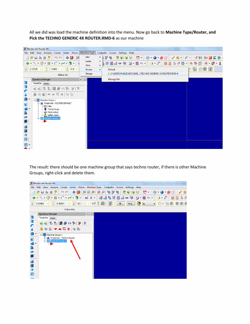
All we did was load the machine definition into the menu. Now go back to Machine Type/Router, and
Pick the TECHNO GENERIC 4X ROUTER.RMD-6 as our machine
The result: there should be one machine group that says techno router, if there is other Machine
Groups, right-click and delete them.
Stock Setup
The Operations Manager is the tool
palette that is docked on the left of
the screen. This displays all the
specific information about the tool
paths (what the CNC router will cut).
Expand the properties tab in the
operations manager. Then click on
stock setup.
Setup the stock:
Enter the measurements for your tray
Y
X
Z
Set the stock origin by clicking on this
corner.
Check “Display”
Click the Green Check Mark (OK)
After you click ok in the stock setup, you should see a red dashed rectangle that represents your stock.
Zoom in or out so that you see the whole piece.
Entering Geometry
It’s time to start drawing some geometry, I’m going to use the measurements from the first drawing on
the document. You must use measurements that work for your application. Please draw out your tray
before you enter the geometry. The coordinates are needed to make sure your layout is correct. For my
tray I can use the rectangle tool. It will be 3 rectangles placed at the correct locations using the
coordinates from 2 corners of each rectangle. For the example I will get the rectangle tool, then enter
the coordinates from the 2 corners: (.25,.25) and (3 7/8,5 ¾).
Rectangle tool
Result:
In my case I want two more rectangles so I will stay in the rectangle tool until those are drawn. You can
tell you are still in the rectangle tool because the rectangle tool options are still active and the prompt
says “select position of the first corner.” So for the example, I will enter (4 1/8, ¼) and (7 ¾, 2 7/8) for the
second rectangle. Then the last set of coordinates for the example are: (4 1/8, 3 1/8) and (7 ¾, 5 ¾). Then