54
BPDB-RPCL POWERGEN LTD. TENDER DOCUMENT FOR CONSTRUCTION OF MIRSARAI 150 MW (±10%) DUAL FUEL (HFO/GAS) POWER PLANT PROJECT. VOLUME 2 OF 2 (PART B) TECHNICAL PARTICULARS JUNE- 2017
BPDB-RPCL POWERGEN LTD.
TENDER DOCUMENT
FOR
CONSTRUCTION OF MIRSARAI 150 MW (±10%) DUAL FUEL (HFO/GAS) POWER PLANT PROJECT.
VOLUME 2 OF 2 (PART B)
TECHNICAL PARTICULARS
JUNE- 2017

2
SCHEDULES AND DRAWINGS 1. Schedules Page
Schedule-A Guarantees ------------------------------------------------ 3 Schedule-B Technical Data Sheet ----------------------------------- 5
Schedule-C Drawings to be furnished with Tender --------------- 40 Schedule-D Delivery Times ------------------------------------------- 42 Schedule-E Tools and Appliances ----------------------------------- 43
Schedule-F Deviations from Specifications ------------------------ 44 Schedule-G Civil and Building Works ------------------------------- 45 Schedule-H List of Subcontractors ---------------------------------- 47 Schedule-I Description of Training Programme ------------------ 48 Schedule-J Mobilisation and demobilisation Schedule for
Construction Equipment ------------------------------- 49 Schedule-K Method of Transportation and Unloading -----------50 Schedule-L List of Manufacturer ------------------------------------ 51 Schedule-M List of Spare parts ------------------------------------ 52
3
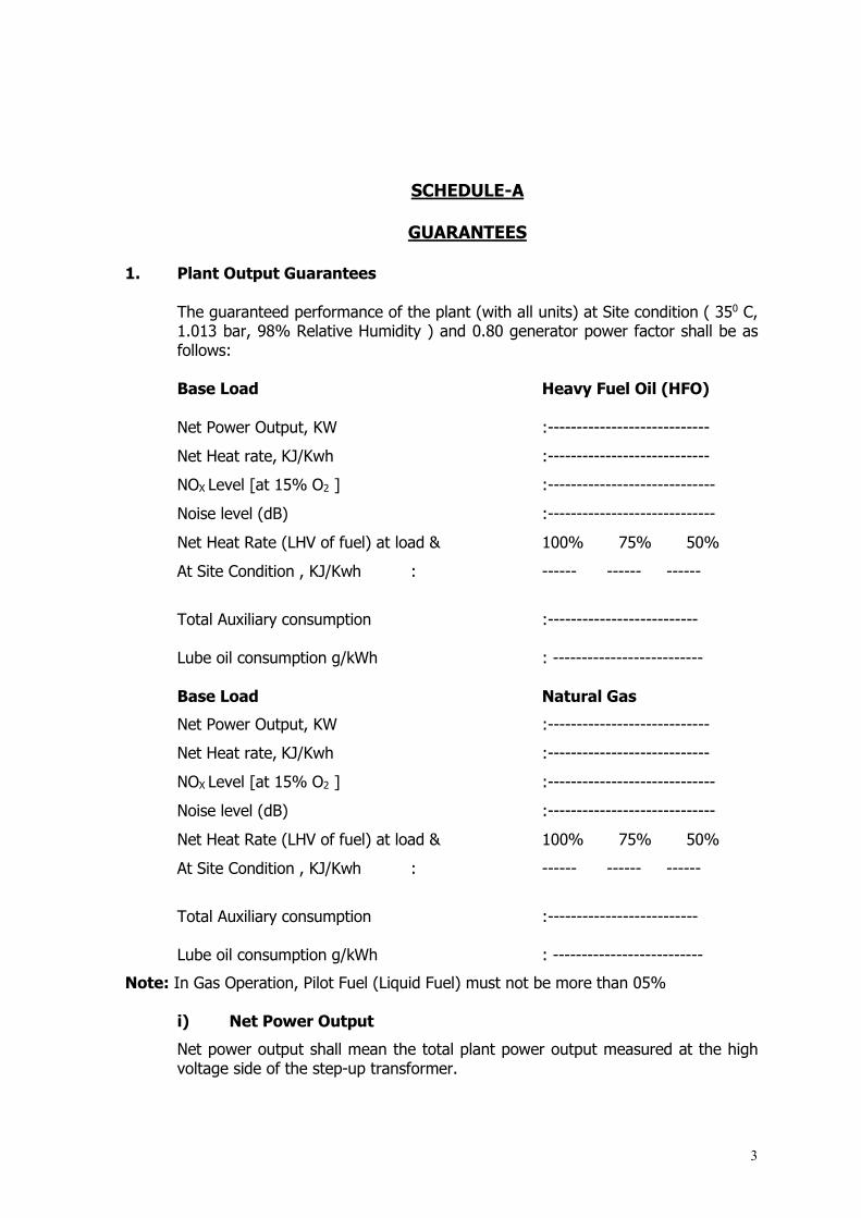
SCHEDULE-A
GUARANTEES
1. Plant Output Guarantees
The guaranteed performance of the plant (with all units) at Site condition ( 350 C, 1.013 bar, 98% Relative Humidity ) and 0.80 generator power factor shall be as follows: Base Load Heavy Fuel Oil (HFO) Net Power Output, KW :----------------------------
Net Heat rate, KJ/Kwh :----------------------------
NOX Level [at 15% O2 ] :-----------------------------
Noise level (dB) :-----------------------------
Net Heat Rate (LHV of fuel) at load & 100% 75% 50%
At Site Condition , KJ/Kwh : ------ ------ ------
Total Auxiliary consumption :-------------------------- Lube oil consumption g/kWh : -------------------------- Base Load Natural Gas
Net Power Output, KW :----------------------------
Net Heat rate, KJ/Kwh :----------------------------
NOX Level [at 15% O2 ] :-----------------------------
Noise level (dB) :-----------------------------
Net Heat Rate (LHV of fuel) at load & 100% 75% 50%
At Site Condition , KJ/Kwh : ------ ------ ------
Total Auxiliary consumption :-------------------------- Lube oil consumption g/kWh : --------------------------
Note: In Gas Operation, Pilot Fuel (Liquid Fuel) must not be more than 05% i) Net Power Output
Net power output shall mean the total plant power output measured at the high voltage side of the step-up transformer.

4
ii) Net Heat Rate
Net heat rate shall mean the heat equivalent of the fuel consumed by the total plant, time based upon the Lower Calorific Value, divided by the net power output as defined above. iii) Fuel
In so far as these performance guarantees are affected, the fuel shall be in accordance with the analysis given in the Technical Specification, (20.4 of Vol 3).
iv) Tolerance
A positive tolerance of 1% in case of Net Heat Rate and no tolerance on Net Power Output shall be allowed. The performance tests shall be carried out on the site in accordance with section 16, Vol. 2 of 3, Technical Specification to prove that the above performance guarantees are available. Also other capability/ parameters shall be verified.
v) Performance Correction Curves
The following curves, which are necessary for correcting Power Output, Heat Rate and Inlet/Outlet Temperature from the test ambient condition to the guarantee reference condition, shall be furnished with the Tender.
- Variation in barometric pressure
- Variation in ambient temperature
- Variation of generator efficiency with Power Factor
- Variation in pressure loss from atmosphere to compressor inlet flange
- Variation in pressure loss from turbine exhaust flange to atmosphere
- Variation in Altitude and Relative Humidity
- Others if any
2. Step-Up Transformers Guarantees The following items shall be guaranteed by the Contractor :
i) Losses
a. Load loss at ONAF rating under the rated voltage, tap and frequency :
-At 0.8 Power Factor, Lagging, KW :----------------------- -At Unity Power Factor, KW :-----------------------
b. No-Load loss under the rated voltage, tap and frequency , KW :-----------------------
ii) Impedance at rated power and frequency, % :----------------------- (Positive Seq. )
3. Date of completion of Initial Commercial Operation
The Initial Commercial Operation of the plant shall be completed within the period after effective Date of Contract.
: ---------------------------------------- days
5
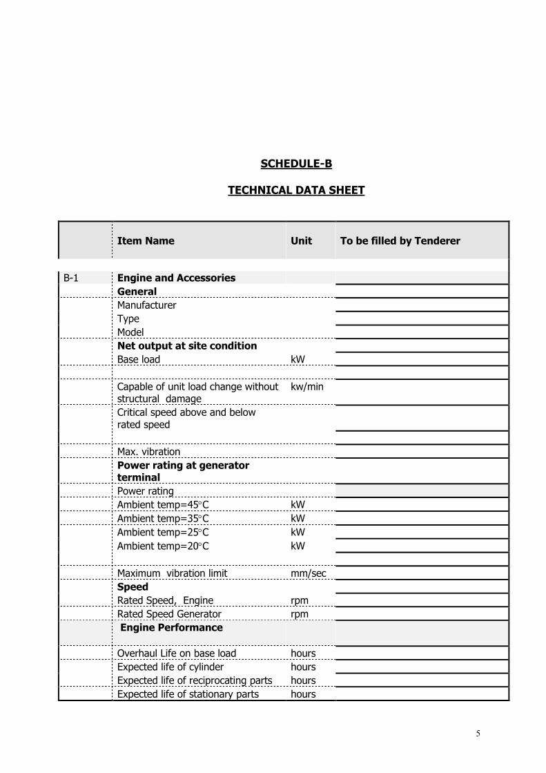
SCHEDULE-B
TECHNICAL DATA SHEET
Item Name
Unit
To be filled by Tenderer
B-1 Engine and Accessories
General
Manufacturer
Type
Model
Net output at site condition
Base load kW
Capable of unit load change without structural damage
kw/min
Critical speed above and below rated speed
Max. vibration
Power rating at generator terminal
Power rating
Ambient temp=45C kW
Ambient temp=35C kW
Ambient temp=25C kW
Ambient temp=20C kW
Maximum vibration limit mm/sec
Speed
Rated Speed, Engine rpm
Rated Speed Generator rpm
Engine Performance
Overhaul Life on base load hours
Expected life of cylinder hours
Expected life of reciprocating parts hours
Expected life of stationary parts hours

6
Item Name
Unit
To be filled by Tenderer
Number of hours of continuous operation allowed at peak output
hours
Number of hours of peak operation allowed per year
hours
Overhaul life on peak load
Overhaul life on number of hours hours
Overhaul life number of starts no.
Starting time from cold in min
starting time from standby in min
Electrical power required for standby
kWh
Indicated hp hp orkW
Brake hp hp orkW
Indicated thermal efficiency
Brake thermal efficiency
Mechanical efficiency
Heat rate 100% 75% 50% 25% 1. Ambient air temp 45C kJ/kWH
2. Ambient air temp 35C kJ/kWH
3. Ambient air temp 25C kJ/kWH
4. Ambient air temp 20C kJ/kWH
Out-put 100% 75% 50% 25% 5. Ambient temp=45C kW
6. Ambient temp=35C kW
7. Ambient temp=25C kW
8. Ambient temp=20C kW
9.
10. Start up time from cold start to
synchronous speed
Normal minut.
Emergency minut.
Capable rated load change
without structural damage
kW/Min
Full Load Heat Balance
Useful work
Cooling
Exhaust
Friction, Radiation and others
Heat input 100 unit
Staring Time hour

7
Item Name
Unit
To be filled by Tenderer
From Cold hour
From Standby
Time required to no load to maximum load
Normal minut.
Emergency minut.
Starting reliability %
Number of consequtive starts to prove reliability
no.
Sound attenuation
100 meter from unit db
50 meter from unit db
1 meter from unit db
Engine data
Number of cylinder no
Piston materials
Piston ring materials
Cylinder with liner material
Max allowable gas temperature after combustion
c
brake mean effective pressure psi
Cylinder bore mm
Piston stroke mm
Mean piston speed mm/sec
Complete engine weight ton
Heaviest piece during erection ton
Heaviest piece after erection (disassembled)
Engine output (On shaft) mw
Specific fuel consumption Nm3/kwh
Cooling system
Type and description
Design ambient temperature for water
c
Lubrication system
Type and description
Capacity of lube-oil storage tank liter
Cap. of maintenance tank liter

8
Item Name
Unit
To be filled by Tenderer
Type of lube-oil purifier
Capacity of lube oil purifier liter/hour
Type of filtration unit
Manufacturer
Type of lube-oil heater
Pre lube-oil pump manufacturer
Type
Motor rating kW
Capacity liter/ hour
Starting system
Type of starter
Manufacturer
Capacity
Type of compressor
Pr. to stop compressor bar
Pr. to start compressor bar
No. of air bottle no
Air bottle capacity liter
Pipe line pr. to the engine bar
Engine intake air filters
Manufacturer
Type
Material
Type of louvers
Turbocharger
Inlet pr. of turbine bar
Exhaust pr. of turbine bar
Suction pr. of compressor bar
Exhaust pr. of compressor bar
Temp. of air after compressor C
Gas Compressor (if required)
Compressor Type
Make, Country
Model
Capacity m3/h
Suction Pressure bar
Discharge Pressure bar
Discharge Temperature C
Compressor Speed rpm
Compressor Motor Voltage/Rating, kV/KW
Motor Speed rpm
Engine governor or control & Hardware
Manufacturer
Type
Main CPU unit specification
Manufacturer
Software manufacturer

9
Item Name
Unit
To be filled by Tenderer
Name of speed regulation
Name of fuel valve control
Maximum speed rise after full load rejection to be guaranteed by contractor
Housing
Material
Finish
Turning gear
Motor rating hp
Main shaft speed on turning gear rpm
fire protection system
Fire Fighting Devices
Manufacturer
Fire water storage tank capacity liter
No of fire hydrants hose cabinets
Fire pump rating(motor driven)
Fire pump rating(Diesel engine driven)
No. of portable extinguishers CO2
Oil-Fuel System
Transfer Pump-Heavy oil
Manufacturer
Number no.
capacity liter/hour
Motor rating kW
Storage Tank-Heavy oil
Capacity liter
Dimension : diameter height
meter meter
Fuel Oil(Day) Tank
Capacity liter
Dimension :diameter meter
height meter
Maintenance Lifting Device
Overhead Maintenance Cranes
Manufacturer
10
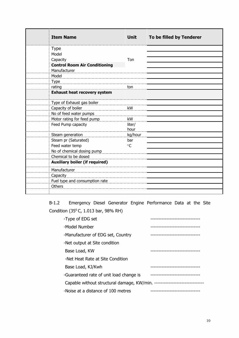
Item Name
Unit
To be filled by Tenderer
Type
Model
Capacity Ton
Control Room Air Conditioning
Manufacturer
Model
Type
rating ton
Exhaust heat recovery system
Type of Exhaust gas boiler
Capacity of boiler kW
No of feed water pumps
Motor rating for feed pump kW
Feed Pump capacity liter/ hour
Steam generation kg/hour
Steam pr (Saturated) bar
Feed water temp C
No of chemical dosing pump
Chemical to be dosed
Auxiliary boiler (if required)
Manufacturer
Capacity
Fuel type and consumption rate
Others
B-1.2 Emergency Diesel Generator Engine Performance Data at the Site
Condition (350 C, 1.013 bar, 98% RH)
-Type of EDG set -------------------------------
-Model Number -------------------------------
-Manufacturer of EDG set, Country -------------------------------
-Net output at Site condition
Base Load, KW -------------------------------
-Net Heat Rate at Site Condition
Base Load, KJ/Kwh -------------------------------
-Guaranteed rate of unit load change is -------------------------------
Capable without structural damage, KW/min. -------------------------------
-Noise at a distance of 100 metres -------------------------------

11
(in each octave band, see section 2, Vol. 2)
-Critical speed above and below --------------------------------
rated speed ---------------------------------
- Engine speed, rpm --------------------------------
-Generator, rpm --------------------------------
-Generator rated Voltage & pf --------------------------------
-Engine Starting System -------------------------------
-Max. starting time required from
standstill to full speed, min --------------------------------
-Max. vibration limit, mm/sec --------------------------------
-Min. time required for applying full
load to unit, ---------------------------------
From cold standby, min ----------------------------------
From warm shutdown, min ----------------------------------
-Estimated hours at or below base rating of
between :
Minor inspection, hours -----------------------------------
Normal inspection, hours -----------------------------------
Major overhaul, hours -----------------------------------
-Estimated shutdown period, hour and
Man-hours for : ---------------------------------
Minor inspection ---------------------------------
Normal inspection ---------------------------------
Major overhaul ---------------------------------
-Number, type and arrangement of
cylinders -------------------------------
-Number of strokes -------------------------------
-Compressor pressure ratio -------------------------------
-Starting system -------------------------------
-Description of Speed governing system
and fuel control system -------------------------------
-Fuel consumption -------------------------------
-Description of cooling system -------------------------------
-Auxiliary power consumption, KW -------------------------------
12
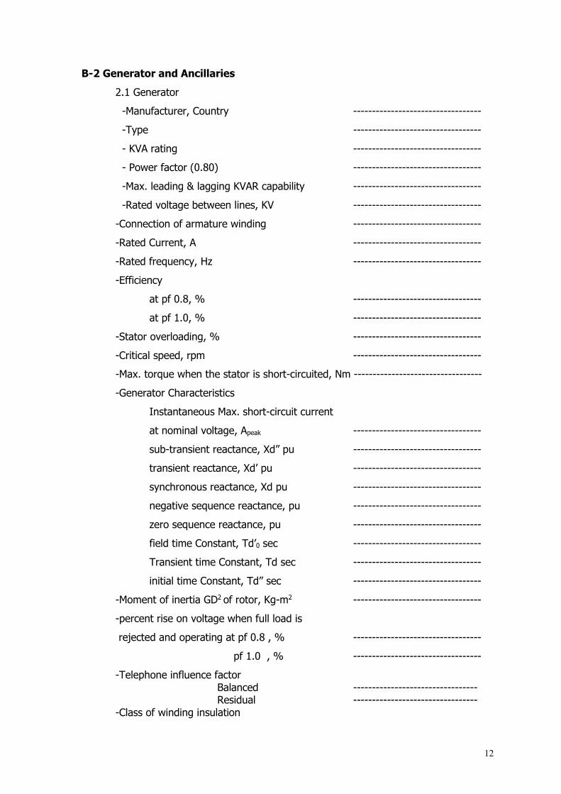
B-2 Generator and Ancillaries
2.1 Generator
-Manufacturer, Country ----------------------------------
-Type ----------------------------------
- KVA rating ----------------------------------
- Power factor (0.80) ----------------------------------
-Max. leading & lagging KVAR capability ----------------------------------
-Rated voltage between lines, KV ----------------------------------
-Connection of armature winding ----------------------------------
-Rated Current, A ----------------------------------
-Rated frequency, Hz ----------------------------------
-Efficiency
at pf 0.8, % ----------------------------------
at pf 1.0, % ----------------------------------
-Stator overloading, % ----------------------------------
-Critical speed, rpm ----------------------------------
-Max. torque when the stator is short-circuited, Nm ----------------------------------
-Generator Characteristics
Instantaneous Max. short-circuit current
at nominal voltage, Apeak ----------------------------------
sub-transient reactance, Xd” pu ----------------------------------
transient reactance, Xd’ pu ----------------------------------
synchronous reactance, Xd pu ----------------------------------
negative sequence reactance, pu ----------------------------------
zero sequence reactance, pu ----------------------------------
field time Constant, Td’0 sec ----------------------------------
Transient time Constant, Td sec ----------------------------------
initial time Constant, Td” sec ----------------------------------
-Moment of inertia GD2 of rotor, Kg-m2 ----------------------------------
-percent rise on voltage when full load is
rejected and operating at pf 0.8 , % ----------------------------------
pf 1.0 , % ----------------------------------
-Telephone influence factor Balanced ---------------------------------
Residual --------------------------------- -Class of winding insulation
13
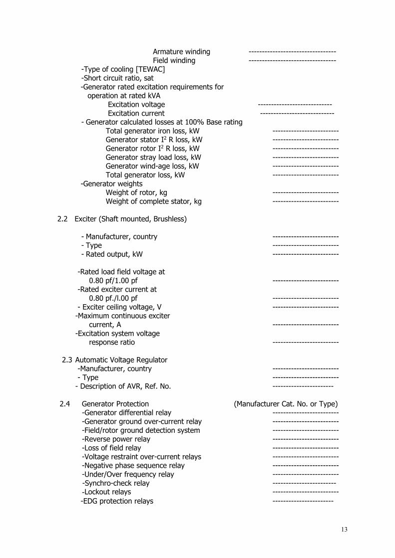
Armature winding --------------------------------- Field winding ---------------------------------
-Type of cooling [TEWAC] -Short circuit ratio, sat -Generator rated excitation requirements for operation at rated kVA
Excitation voltage ---------------------------- Excitation current ----------------------------
- Generator calculated losses at 100% Base rating Total generator iron loss, kW ------------------------- Generator stator I2 R loss, kW ------------------------- Generator rotor I2 R loss, kW ------------------------- Generator stray load loss, kW ------------------------- Generator wind-age loss, kW ------------------------- Total generator loss, kW -------------------------
-Generator weights Weight of rotor, kg ------------------------- Weight of complete stator, kg -------------------------
2.2 Exciter (Shaft mounted, Brushless)
- Manufacturer, country ------------------------- - Type ------------------------- - Rated output, kW -------------------------
-Rated load field voltage at 0.80 pf/1.00 pf ------------------------- -Rated exciter current at 0.80 pf./l.00 pf ------------------------- - Exciter ceiling voltage, V ------------------------- -Maximum continuous exciter current, A ------------------------- -Excitation system voltage response ratio ------------------------- 2.3 Automatic Voltage Regulator -Manufacturer, country ------------------------- - Type ------------------------- - Description of AVR, Ref. No. ----------------------- 2.4 Generator Protection (Manufacturer Cat. No. or Type) -Generator differential relay ------------------------- -Generator ground over-current relay ------------------------- -Field/rotor ground detection system ------------------------- -Reverse power relay ------------------------- -Loss of field relay ------------------------- -Voltage restraint over-current relays ------------------------- -Negative phase sequence relay ------------------------- -Under/Over frequency relay ------------------------- -Synchro-check relay ------------------------ -Lockout relays ------------------------- -EDG protection relays -----------------------

14
-Auxiliary relays ------------------------ -Inter-connection protection [main & back-up] from plant to grid ------------------------
-Others: Specify ----------------------
B-3 11 KV Switchgear Generator Switchgear -Manufacturer, country ------------------------- -Circuit breaker Catalogue No. ------------------------- Type ------------------------- Closing current at 125 volts DC, A ------------------------- Time to close, m sec ------------------------- Tripping current at 125 volts DC, A ------------------------- Time to trip, m sec ------------------------- - Rating and capabilities
Current rating, A ------------------------- Voltage rating, V -------------------------
Nominal 3 phase interrupting capacity, MVA ------------------------- Maximum symmetrical interrupting capacity, kA -------------------------
3 second short time rating, kA ------------------------- Closing and latching capability, kA ------------------------- - Operating Mechanism ----------------------
-Instruments and devices Manufacturer Type
Current transformers Single ratio ------------------------- Multi ratio ------------------------- Potential transformers ------------------------- Control and instrument switches ------------------------- Indicating lights -----------------------
-Lightning arresters ------------------------- -Surge protection devices ------------------------- -Type of bus insulation ------------------------- -Type of bus supports ------------------------- -Type of insulation on connections ------------------------- -Size of completely assembled switchgear
Length, mm ------------------------- Width, mm -------------------------
Height, mm ------------------------- - Total weight of switchgear, kg ------------------------- -Attached type test report, No -------------------------
B-4 230 kV Equipment 4.1 230 kV Circuit Breaker
- Manufacturer, Country ------------------------- - Type designation -------------------------
15
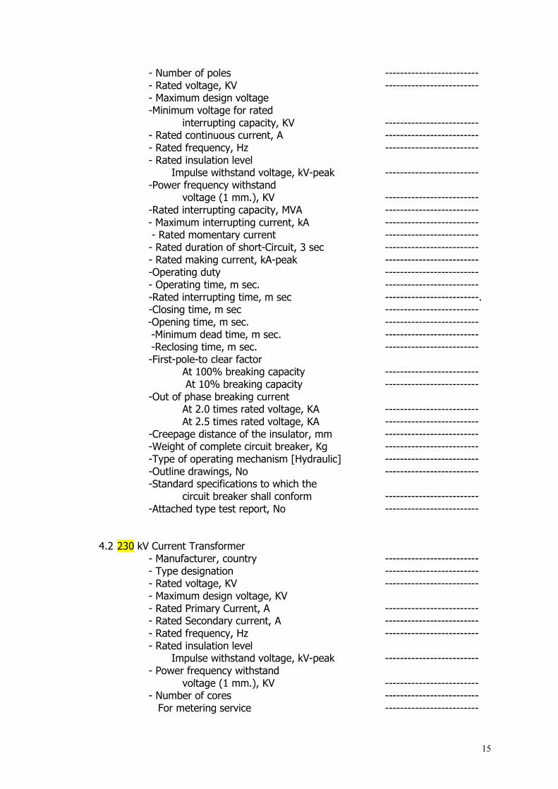
- Number of poles ------------------------- - Rated voltage, KV ------------------------- - Maximum design voltage -Minimum voltage for rated interrupting capacity, KV -------------------------
- Rated continuous current, A ------------------------- - Rated frequency, Hz ------------------------- - Rated insulation level
Impulse withstand voltage, kV-peak ------------------------- -Power frequency withstand
voltage (1 mm.), KV ------------------------- -Rated interrupting capacity, MVA -------------------------
- Maximum interrupting current, kA ------------------------- - Rated momentary current -------------------------
- Rated duration of short-Circuit, 3 sec ------------------------- - Rated making current, kA-peak ------------------------- -Operating duty -------------------------
- Operating time, m sec. ------------------------- -Rated interrupting time, m sec -------------------------. -Closing time, m sec -------------------------
-Opening time, m sec. ------------------------- -Minimum dead time, m sec. ------------------------- -Reclosing time, m sec. -------------------------
-First-pole-to clear factor At 100% breaking capacity ------------------------- At 10% breaking capacity ------------------------- -Out of phase breaking current At 2.0 times rated voltage, KA ------------------------- At 2.5 times rated voltage, KA ------------------------- -Creepage distance of the insulator, mm ------------------------- -Weight of complete circuit breaker, Kg ------------------------- -Type of operating mechanism [Hydraulic] ------------------------- -Outline drawings, No ------------------------- -Standard specifications to which the circuit breaker shall conform ------------------------- -Attached type test report, No -------------------------
4.2 230 kV Current Transformer
- Manufacturer , country ------------------------- - Type designation ------------------------- - Rated voltage, KV ------------------------- - Maximum design voltage, KV - Rated Primary Current, A -------------------------
- Rated Secondary current, A ------------------------- - Rated frequency, Hz ------------------------- - Rated insulation level
Impulse withstand voltage, kV-peak ------------------------- - Power frequency withstand
voltage (1 mm.), KV ------------------------- - Number of cores -------------------------
For metering service -------------------------

16
For relaying service ------------------------- - Accuracy Class -------------------------
For metering service ------------------------- For relaying service -------------------------
- Rated Burden ------------------------- For metering service, VA -------------------------. For relaying service, VA -------------------------
- Rated continuous thermal current, % - Short-time current rating,(1 sec), KA -------------------------
- Creepage distance of insulator, mm ------------------------- - Weight of single phase unit, Kg -Out line drawing, No ------------------------- -Standard specification to which the CT shall conform ------------------------- -Attached type test report, No -------------------------
4.3 230 KV Voltage Transformer
- Manufacturer , country ------------------------- - Type designation ------------------------- - Rated voltage, KV ------------------------- - Maximum design voltage, KV ------------------------- - Rated Primary Voltage, KV -------------------------
- Rated Secondary Voltage, V ------------------------- - Rated Secondary Voltage, V ------------------------- - Rated frequency, Hz ------------------------- - Rated insulation level
Impulse withstand voltage, kV-peak ------------------------- - Power frequency withstand
voltage (1 mm.), KV ------------------------- - Number of cores -------------------------
For metering service ------------------------- For relaying service -------------------------
- Accuracy Class ------------------------- For metering service ------------------------- For relaying service -------------------------
- Rated Burden ------------------------- For metering service, VA -------------------------. For relaying service, VA -------------------------
- Rated continuous thermal current, % - Short-time current rating,(1 sec), KA -------------------------
- Creepage distance of insulator, mm ------------------------- - Weight of single phase unit, Kg -Out line drawing, No ------------------------- -Standard specification to which the PT shall conform ------------------------- -Attached type test report, No -------------------------
4.4 230 KV Lightning Arrester
- Manufacturer , country ------------------------- - Type designation -------------------------

17
- Rated voltage, KV ------------------------- - Maximum design voltage, KV -------------------------
- Rated frequency, Hz ------------------------- - Rated discharge current, KA ------------------------- - Min. power frequency spark-over voltage ------------------------- -Impulse protective level Max. spark-over voltage for a standard
full wave, KVpeak ------------------------- Max. front wave impulse spark-over voltage, KVpeak ------------------------- Max. discharge voltage at the rated discharge current, KVpeak -------------------------
- Creepage distance of insulator, mm ------------------------- - Weight of single phase unit, Kg ------------------------- - Type of operating counter ------------------------- -Out line drawing, No ------------------------- -Standard specification to which the LA shall conform ------------------------- -Attached type test report, No -------------------------
4.5 230KV Isolators - Manufacturer, Country -------------------------
- Type ------------------------- - Rated voltage, KV -------------------------
- Rated normal current, A ------------------------- - Rated short time withstand duration, 1 sec., KA ----------------------
3 sec., KA ------------------------- Dynamic peak, KA ------------------------- - Impulse withstand voltage Across the isolating distance, KVpeak ------------------------- To earth and between poles, KVpeak ------------------------- - Power Frequency withstand voltage, 1 min. Across the isolating distance, KV ------------------------- To earth and between poles, KV ------------------------- - Operating mechanism ------------------------- - Number of auxiliary contacts ------------------------- - Method of interlocking ------------------------- - Creepage distance of insulators ------------------------- - Weight of complete Isolator -------------------------
- Out line drawing, No ------------------------- - Standard specification to which the Isolator shall conform -------------------------
-Attached type test report, No ------------------------- 4.6 Steel Structure - Manufacturer, country -------------------------
- Standard specifications to which the ------------------------- steel structure shall conform

18
-Type ------------------------- -Minimum thickness of members ------------------------- - Outline drawings -------------------------
4.7 Busbar and Connectors (Busbar / Bay Extension)
- Manufacturer , country ------------------------- - Standard specifications to which the busbar and connectors shall conform -------------------------
-Type of busbar ------------------------- - Characteristics of bus conductor
Material ------------------------- Nominal sectional area ------------------------- Construction of conductor ------------------------- Calculated sectional area ------------------------- - Ultimate minimum breaking strength, kg -------------------------
- Outside diameter, mm ------------------------- -Standard unit weight, kg/ m -------------------------
-Calculated resistance at 200C, ohm / Km ------------------------- -Outline drawing of conductor, No. ------------------------- -Outline drawing of connection, No’s ------------------------- 4.8 Post Insulator (if any)
- Manufacturer , country ------------------------- - Number of units in complete post insulator ------------------------- - Diameter (max.), mm ------------------------- - Length of each unit, mm ------------------------- - Weight of complete post insulator, Kg ------------------------- - Creepage distance , mm -------------------------
- Min. Power frequency (dry) flash-over voltage, KV -------------------------
- 50% lightning impulse (+ve), KV ------------------------- - 50% lightning impulse (-ve), KV ------------------------- - Max. vertical working load Tension, Kg ------------------------- Compression, Kg ------------------------- - Mechanical routine test load (tension), Kg ------------------------- - Mechanical type test load (tension), Kg ------------------------- - Vertical breaking load (tension), Kg ------------------------- - Max. torsional working load, Kg-m ------------------------- - Max. cantilever working load (complete post insulator), Kg ------------------------- - Min. cantilever breaking load upright (complete post insulator), Kg ------------------------- - Outline drawings -------------------------
- Standard specification to which the Post Insulator shall conform -------------------------
4.9 Suspension Insulator Assembly (if any)
19
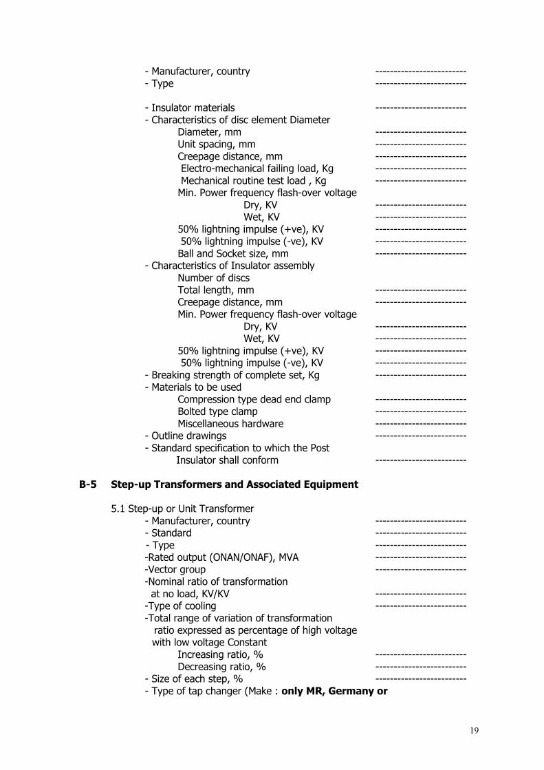
- Manufacturer, country ------------------------- - Type ------------------------- - Insulator materials -------------------------
- Characteristics of disc element Diameter Diameter, mm ------------------------- Unit spacing, mm ------------------------- Creepage distance, mm ------------------------- Electro-mechanical failing load, Kg ------------------------- Mechanical routine test load , Kg ------------------------- Min. Power frequency flash-over voltage Dry, KV ------------------------- Wet, KV ------------------------- 50% lightning impulse (+ve), KV ------------------------- 50% lightning impulse (-ve), KV ------------------------- Ball and Socket size, mm -------------------------
- Characteristics of Insulator assembly Number of discs
Total length, mm ------------------------- Creepage distance, mm ------------------------- Min. Power frequency flash-over voltage Dry, KV ------------------------- Wet, KV ------------------------- 50% lightning impulse (+ve), KV ------------------------- 50% lightning impulse (-ve), KV ------------------------- - Breaking strength of complete set, Kg ------------------------- - Materials to be used Compression type dead end clamp ------------------------- Bolted type clamp ------------------------- Miscellaneous hardware ------------------------- - Outline drawings -------------------------
- Standard specification to which the Post Insulator shall conform ------------------------- B-5 Step-up Transformers and Associated Equipment 5.1 Step-up or Unit Transformer
- Manufacturer, country ------------------------- - Standard -------------------------
- Type ------------------------- -Rated output (ONAN/ONAF), MVA ------------------------- -Vector group ------------------------- -Nominal ratio of transformation at no load, KV/KV ------------------------- -Type of cooling ------------------------- -Total range of variation of transformation ratio expressed as percentage of high voltage
with low voltage Constant Increasing ratio, % ------------------------- Decreasing ratio, % -------------------------
- Size of each step, % ------------------------- - Type of tap changer (Make : only MR, Germany or

20
ABB, Sweden) ------------------------ - Type of gas/oil actuated relay -------------------------
- Impedance voltage at 759C expressed as a percentage of normal voltage (ONAF rating)
At highest ratio, % ------------------------- At normal ratio, % ------------------------- At lowest ratio, % -------------------------
- Voltage regulation at normal ratio, 750C and a power factor of, Unity, % ------------------------- 0.8, % ------------------------- - Magnetising current at normal ratio High tension winding, A ------------------------- Low tension winding, A -------------------------
-Auxiliary Plant losses Forced air plant, KW -------------------------- -Fixed losses at normal ratio and 750C, KW -------------------------- -Load losses at IEC rating, normal ratio and 750 C ONAF rating, pf 1.0/0.8, KW ------------------------- ONAN rating, pf 1.0/0.8, KW ------------------------- -Total losses at IEC rating, normal ratio and 750C At ONAF rating, pf 1.0/0.8, KW -------------------------
At ONAN rating, pf 1.0/0.8, KW ------------------------- -Efficiency at IEC rating normal ratio and 75'C
At ONAF rating, pf 1.0/ 0.8, % ------------------------- At ONAN rating, pf 1.0/0.8, % ------------------------- -Type of transformer, shell or core ------------------------- -Type of core joint Minimum magnetic flux density in core iron at normal voltage and frequency based upon the net section of iron Cores, T ------------------ Yoke, T -------------------------
-Type of windings High tension winding -------------------------
Low tension winding ------------------------- - Maximum current density in windings
High tension winding, A/ sq. mm ----------------------- Low tension winding, A/ sq. mm ------------------------- -Type of radial coil supports High tension winding ------------------------- Low tension winding ------------------------- -Type of insulation used for, High tension winding ------------------------- Low tension winding ------------------------- -Tapping ------------------------- -Tapping connection ------------------------- -Core bolts ------------------------- -Core bolt washers -------------------------

21
-Maximum observable oil temperature at IEC rating, 0C ------------------------- - Calculated thermal time Constant At ONAF rating, hour ------------------------- At ONAN rating, hour ------------------------- -Type of winding maximum temperature indicator ------------------------- -Total quantity of oil required to fill complete transformer up to lowest visible level in conservator, litres ------------------------- -Volume of oil to be removed to the level of the top yoke, litres ------------------------- -Volume of oil required to raise oil in conservator from lowest visible level to highest level, litres ------------------------- -Total volume of conservators, litres ------------------------- -High above transformer foundation pad of conservator highest oil, mm ------------------------- -Proposed filling medium for transformers shipped light and empty of oil ------------------------- -Makes and grades of oil suitable for filling transformer ------------------------- -Thickness of transformer tank Sides, mm ------------------------- Bottom, mm ------------------------- -Number of cooling fan unit ------------------------- -Surface area of each cooler unit, mm2 ------------------------- -Heat dissipation of each cooler unit as percentage of total heat dissipation at IEC rating, % ------------------------- -Average rate of oil flow through each cooler unit, litres/min ------------------------- -Weight of parts Weight of copper, Kg ------------------------- Weight of core sheets, Kg ------------------------- Weight of all other ferrous parts, Kg ------------------------- -Weight of core and winding assembly, Kg ------------------------- -Weight of complete transformer, Kg ------------------------- -Weight of transformer arranged for shipment, Kg ------------------------- -Dimension of transformer including all fittings Length, mm ------------------------- Breadth, mm ------------------------- Height, mm ------------------------- -Dimension of transformer arranged
for shipment Length, mm ------------------------- Breadth, mm ------------------------- Height, mm ------------------------- -Weight of each cooler, Kg -Lightning impulse insulation level High tension winding, KV peak ------------------------- Low tension winding, KV peak ------------------------- High tension neutral, KV peak -------------------------

22
-Power frequency withstand voltage for 1 minute High tension winding, KV ------------------------- Low tension winding, KV ------------------------- - Temperature rise Winding, 0C ------------------------- Top insulation oil, 0C -------------------------
- Audible sound level at 1 meter from transformer surface, dB -------------------------
-Creepage distance of bushing High tension bushing, mm ------------------------- Low tension bushing, mm ------------------------- Neutral bushing, mm ------------------------- Outline drawing, No ------------------------- -Attached type test report, No ------------------------- 5.2 Transformer Protection (Manufacturer Cat. No. or Type) - Differential relay ------------------------- - Restricted Earth Fault relay ------------------------- - over-current relays (LV & HV) ------------------------- - Earth Fault relays (HV, LV & Neutral) ------------------------- - Pressure relays ------------------------- - Temperature relays ------------------------- - Lockout relays ------------------------- - Auxiliary relays ------------------------- - Others: specify ---------------------- B-6 Station Transformers - Manufacturer, country ------------------------- - Cooling class ------------------------- - Continuous kVA rating, kVA -------------------------
- Impedance at maximum kVA with ONAN rating, % ------------------------- -Guaranteed efficiency at 100
per cent of maximum kVA with ONAN rating, % -------------------------
- Standard, IEC ------------------------- -Excitation current at 100 per cent rated voltage,
in per cent based on maximum kVA with ONAN rating, % -------------------------
- Guaranteed losses at 100 percent rated voltage No load loss, kW -------------------------
Total losses at maximum with ONAN rating, kW ------------------------- Manufacturer Type
-Bushing High voltage -------------------------
Low voltage ------------------------- Neutral -------------------------

23
- Current transformers ------------------------- - Approximate weight, Kg -------------------------
- Total assembled, Kg ------------------------- - Type of oil preserver system, Ref. No ------------------------- -Primary and secondary voltage, V ------------------------- - No. of taps ------------------------- - Tap range ------------------------- - Vector group ------------------------- - Class of insulation ------------------------- - Temperature rise at, 0C ------------------------- - ambient temperature, 0C ---------------------- - Winding temperature, 0C ------------------------- - Oil temperature, 0C ------------------------- Transformers Protection (Manufacturer Cat. No. or Type) - over-current relays (LV & HV) ------------------------- - Earth Fault relays (HV & LV) ------------------------- - Pressure relays ------------------------- - Lockout relays ------------------------- - Auxiliary relays ------------------------- B-7 Unit Auxiliary Transformer
- Manufacturer , country ------------------------- - Cooling class -------------------------
- Continuous kVA rating, kVA ------------------------- - Impedance at maximum kVA with ONAN rating, % ------------------------- - Guaranteed efficiency at 100 per cent of maximum kVA with ONAN rating, % ------------------------- - Standard ------------------------- - Excitation current at 100 per cent rated voltage, in per
cent based on maximum kVA with ONAN rating, % -------------------------
- Guaranteed losses at 100 per cent rated voltage
No load loss, kW ------------------------- Total losses at maximum with
ONAN rating, kW ------------------------- Manufacturer Type
-Bushing High voltage ------------------------- Low voltage ------------------------- Neutral -------------------------
-Current transformers ------------------------- -Approximate weight, kg -------------------------
-Total assembled, Kg ------------------------- -Type of oil preserver system, Ref. No. -------------------------
- Primary and secondary voltage, V -------------------------
24
- No. of taps ------------------------- - Tap range ------------------------- - Vector group ------------------------- - Class of insulation ------------------------- - Temperature rise at 400C , 0C -------------------------
-ambient temperature, 0C ------------------------- - Winding temperature, 0C ------------------------- Oil temperature, 0C ------------------------- Transformer Protection (Manufacturer Cat. No. or Type) - Differential relay ------------------------- - Restricted Earth Fault relay ------------------------- - over-current relays (LV & HV) ------------------------- - Earth Fault relays (HV, LV & Neutral) ------------------------- - Pressure relays ------------------------- - Temperature relays ------------------------- - Lockout relays ------------------------- - Auxiliary relays -------------------------
(Note: The Tenderer shall attach additional sheets as required)
B-8 6.6 kV Switchgear (if required)
- Manufacturer, country ------------------------- - Circuit breaker -------------------------
-Catalogue number ------------------------- -Type ------------------------- -Operating mechanism -------------------------
Closing current at 125 volts DC, A ------------------------- Time to close, m sec ------------------------- Tripping current at 125 volts DC, A ------------------------- Time to close, m sec -------------------------
- Rating and capabilities Current rating, A ------------------------- Voltage rating, A ------------------------- Nominal 3 phase interrupting capacity, MVA ------------------------- Maximum symmetrical interrupting capacity at 6.6 kV, kA (rms) 3 second short time rating, kA (rms) ------------------------- Closing and latching capability, kA(rms) ------------------------- - Protective relays Manufacturer Type
Phase over-current ------------------------- Ground over-current ------------------------- Transformer differential -------------------------
- Type of bus insulation ------------------------- - Type of bus supporters ------------------------- - Type of insulation on connections ------------------------- - Size of completely assembled switchgear -------------------------
Length, mm ------------------------- Width, mm ------------------------- Weight, Kg -------------------------

25
- Total weight of switchgear, Kg ------------------------- B-9 415 V Switchgear and Motor Control Centre 9.1 415 V Switchgear and Motor Control Centre - Manufacturer , country ------------------------- Manufacturer Type
- Air circuit breaker Type designation -------------------------
Nominal current, A ------------------------- Rated Voltage, V ------------------------- Method of closing ------------------------- Power required to: Close ------------------------- Open ------------------------- Short circuit current rating, kA ------------------------- Short circuit current, 3 sec, kA ------------------------- Combination starter units ------------------------- Starter contactor ------------------------- Manufacturer Type Control transformer ------------------------- Circuit breaker ------------------------- Starter contactor coil ------------------------- operating characteristics Size1 Size2 Minimum pickup, V ------------------------- Maximum dropout, V ------------------------- Dimension of each switchgear PCC MCC Length, mm ------------------------- Depth, mm ------------------------- Height, mm ------------------------- Weight, Kg ------------------------- Number of vertical section ------------------------- 9.2 Switchboard Design - Degree of protection ------------------------- -Short time rating Current, kA ------------------------- Associated time, sec ------------------------- - Type of insulation provided on
bus bars and connections ------------------------- - Type of protection provided within cubicles(shutter, insulating, cover, etc) -------------------------
-Bus bars ------------------------- Current rating of bus bars, A ------------------------- System short time current,
3 sec, kA ------------------------- Short time current rating, 3 sec, KA -------------------------

26
Bus bar material Cross sectional area of bus, mm2 -------------------------
-Type of connection ------------------------- - Minimum clearance in air:
Between phases, mm ------------------------- Live parts and earth, mm ------------------------- B-10 DC Supply System 10.1 Battery Units (125 V) - Manufacturer, country ------------------------------------ - Type ------------------------------------ - Catalogue No. ------------------------------------
-Capacity (AH at 5 Hr discharge) ------------------------------------
-Number of cells per unit ------------------------------------ -Weight per cell, kg ------------------------------------ -Total battery weight, kg ------------------------------------ -Overall dimension of battery rack length, mm ------------------------------------ Width, mm ------------------------------------ Height, mm ------------------------------------ 10.2 Battery Chargers
- Manufacturer, country ------------------------------------ - Type ------------------------------------ - Capacity, A/kW ------------------------------------
- DC Voltage adjusting range ------------------------------------ B-11 Lighting and Small Power Supply Manufacturer Cat. No. or Type
- Panel boards, AC ------------------------------------ -Panel boards, DC ------------------------------------ - Lighting fixtures ------------------------------------
B-12 Control and Protection System (for each unit, transformer, auxiliary etc.) 12.1 Control and Protection panel -Manufacturer, country ------------------------------------ -Type of construction ------------------------------------ -Dimension, mm ------------------------------------
-Instrument ------------------------------------ AC Voltmeter ------------------------------------ AC Ammeter ------------------------------------ Power factor meter ------------------------------------ Wattmeter ------------------------------------ Varmeter ------------------------------------

27
Synchroniser ------------------------------------ Annunciator ------------------------------------ Watt-hour meter ------------------------------------ Var-hour meter ------------------------------------ Control switch ------------------------------------ -Protection relay Gen. protection relays ------------------------------------ Transformer protection relays ------------------------------------ Gen. Bus protection relays ------------------------------------ Inter-connection protection relays ------------------------------------ Auxiliary system protection relays ------------------------------------ EDG protection relays ------------------------------------ -Lockout relays ------------------------------------
-Control relays ------------------------------------ -Trip relays ------------------------------------ -Auxiliary relays ------------------------------------ (Note: The Tenderer shall attach additional sheets as required.) 12.2 Descriptive Matter -Control system /HMI [Local & Remote], Ref. No. ------------------------------------ -Protection system, Ref. No. ------------------------------------ -Data logging system, Ref. No. ------------------------------------ -List of annunciator, Ref. No. ------------------------------------ -Drawing of panels, Ref. No. ------------------------------------ -Detail of GT Control, ------------------------------
12.3 -Description of standard Weather Station and also to interface with Automatic Plant Control, Protection & Monitoring System, Ref. No. --------------------------------- 12.4 Description of Continuous Emission Monitor Module and also to interface with Automatic Plant Control, Protection & Monitoring System, Ref. No. ---------------------------------
B-13 Cabling and Grounding 13.1 230 kV Power Cable (Single-core XLPE, Copper) -Manufacturer, country ------------------------------------ -Type designation ------------------------------------ -Applicable standard ------------------------------------ -Insulation material ------------------------------------ -Cross-section of conductor, mm2 ------------------------------------
-Conductor material Type of conductor (round, stranded, compacted) ------------------------------------ -Outer sheath material ------------------------------------
28
-Min. Permissible bending radius, mm ----------------------------------
-Weight per meter, Kg ------------------------------------ -Delivery length, meter ------------------------------------ -Voltage designation, V ------------------------------------
-Max. operating voltage ------------------------- -Current carrying capacity at temperatures........ ------------------------- at laying conditions... -------------------------
-1 sec. short circuit current after full load at 700 C cond. temp., A ------------------------------------ -Max. conductor resistance at 200C DC, Ohm / KM ------------------------------------ AC, Ohm / KM ------------------------------------ (Note: The Tenderer shall attach additional sheets as required.)
13.2 11 kV Bus Duct and Power Cable (XLPE, Copper)
-Manufacturer, country ------------------------------------ -Type designation ------------------------------------ -Applicable standard ------------------------------------ -Number of cores ------------------------------------ -Insulation material ------------------------------------ -Cross-section of conductor, mm2 ------------------------------------
-Conductor material Type of conductor (round, stranded, compacted) ------------------------------------ -Outer sheath material ------------------------------------ - Min. Permissible bending radius, mm ----------------------------------
-Weight per meter, Kg ------------------------------------ -Delivery length, meter ------------------------------------ -Voltage designation, V ------------------------------------ -1 sec. short circuit current after full load at 700 C cond. temp., A ------------------------------------ -Max. conductor resistance at 200C DC, Ohm / KM ------------------------------------ AC, Ohm / KM ------------------------------------ (Note: The Tenderer shall attach additional sheets as required.) 13.3 6.6 kV Power Cable (XLPE, Copper) (if required)
-Manufacturer, country ------------------------------------ -Type designation ------------------------------------ -Applicable standard ------------------------------------ -Number of cores ------------------------------------ -Insulation material ------------------------------------ -Cross-section of conductor, mm2 ------------------------------------ -Conductor material ------------------------------------ -Type of conductor
29
(round, stranded, compacted) ------------------------------------ -Outer sheath material ------------------------------------ -Min. Permissible bending radius, mm ------------------------------------ -Weight per meter, Kg ------------------------------------ -Delivery length, meter ------------------------------------ -Voltage designation, V -1 sec. short circuit current after full load at 700 C cond. temp., A ------------------------------------ -Max. conductor resistance at 200C
DC, ohm/KM ------------------------------------ AC, ohm/KM ------------------------------------
(Note: The Tenderer shall attach additional sheets as required.) 13.4 600 V Power Cable(Copper)
-Manufacturer, country ------------------------------------ -Type designation ------------------------------------ -Applicable standard ------------------------------------ -Number of cores ------------------------------------ -Insulation mater ------------------------------------
- Cross section of conductor, mm2 ------------------------------------ -Conductor material ------------------------------------ - Type of conductor (round, stranded, compacted) ------------------------------------ - Outer sheath material ------------------------------------ - Min. Permissible bending radius, mm ------------------------------------ - Weight per meter, Kg ------------------------------------ - Delivery length, meter
-Voltage designation, V ------------------------------------ -1 sec. short circuit current after
full load at 700 C cond. temp. ------------------------------------ 13.5 Control and Instrument Cable(Copper)
a. -Type ------------------------------------ -Manufacturer, country ------------------------------------ -Applicable standard ------------------------------------ -Insulation material ------------------------------------ -Number of cores ------------------------------------
- Core size, mm2 ------------------------------------ - Outer sheath material ------------------------------------ -Weight per meter, kg ------------------------------------ - Delivery length, m ------------------------------------
b.
30
-Type ------------------------------------ -Manufacturer, country ------------------------------------ -Applicable standard ------------------------------------ -Insulation material ------------------------------------ -Number of cores ------------------------------------
- Core size,mm2 ------------------------------------ - Over sheath material ------------------------------------ - Weight per meter, kg ------------------------------------ -Delivery length, m ------------------------------------ (Note: The Contractor shall attach additional sheets as required.) 13.6 Grounding Wire - Manufacturer, country ------------------------------------ - Conductor size, mm2 ------------------------------------ - Conductor material ------------------------------------ - Type of Conductor ------------------------------------ - Short circuit current for 3 sec., A ------------------------------------ - Weight per meter, kg ------------------------------------ - Delivery length, m ------------------------------------ B-14 Maintenance Facilities 14.1 Over head electric Crane - Manufacturer, country ------------------------------------ -Type ------------------------------------
- Maximum safe working load Main hoist, slow speed, Kg ------------------------------------ Main hoist, fast speed, Kg ------------------------------------ Auxiliary hoist, Kg ------------------------------------ -Test load for crane, Kg ------------------------------------ -Span of crane, Centre to Centre of gantry rails, m------------------------------------
-Geared Speeds a) Main hoist, slow speed Raising with full load , m/min ---------------------------------
Raising with no load, m/min --------------------------------- Lowering with full load, m/min --------------------------------- Lowering with no load , m/min --------------------------------- Creep speed, m/min ---------------------------------
b) Main hoist, fast speed Raising with full load, m/min ---------------------------------
Raising with no load, m/min --------------------------------- Lowering with full load, m/min --------------------------------- Lowering with no load , m/min --------------------------------- Creep speed, m/min --------------------------------- c) Auxiliary hoist Raising with full load, m/min --------------------------------- Raising with no load, m/min --------------------------------- Lowering with full load, m/min ---------------------------------
31
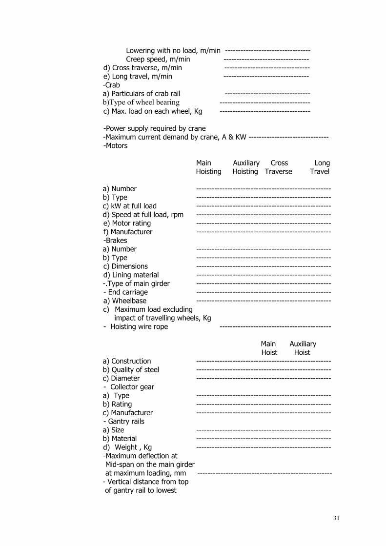
Lowering with no load, m/min --------------------------------- Creep speed, m/min --------------------------------- d) Cross traverse, m/min --------------------------------- e) Long travel, m/min ---------------------------------
-Crab a) Particulars of crab rail --------------------------------- b)Type of wheel bearing -----------------------------------
c) Max. load on each wheel, Kg -----------------------------------
-Power supply required by crane -Maximum current demand by crane, A & KW -------------------------------
-Motors Main Auxiliary Cross Long Hoisting Hoisting Traverse Travel
a) Number ---------------------------------------------------- b) Type ----------------------------------------------------
c) kW at full load ---------------------------------------------------- d) Speed at full load, rpm ----------------------------------------------------
e) Motor rating ---------------------------------------------------- f) Manufacturer ----------------------------------------------------
-Brakes a) Number ---------------------------------------------------- b) Type ----------------------------------------------------
c) Dimensions ---------------------------------------------------- d) Lining material ----------------------------------------------------
-.Type of main girder ---------------------------------------------------- - End carriage ---------------------------------------------------- a) Wheelbase ----------------------------------------------------
c) Maximum load excluding impact of travelling wheels, Kg
- Hoisting wire rope ------------------------------------------- Main Auxiliary Hoist Hoist
a) Construction ---------------------------------------------------- b) Quality of steel ---------------------------------------------------- c) Diameter ---------------------------------------------------- - Collector gear
a) Type ---------------------------------------------------- b) Rating ---------------------------------------------------- c) Manufacturer ---------------------------------------------------- - Gantry rails a) Size ---------------------------------------------------- b) Material ----------------------------------------------------
d) Weight , Kg ---------------------------------------------------- -Maximum deflection at Mid-span on the main girder at maximum loading, mm ---------------------------------------------------- - Vertical distance from top of gantry rail to lowest

32
overhead obstruction required, m------------------------------------------------ - Weights
a) Net weight of complete crane, Kg ------------------------------------------- b) Net weight of complete crab, Kg --------------------------------------------
c) Weight of motors, Kg ------------------------------------------- 14.2 Hydraulic Mobile Crane -Manufacturer, country ----------------------------
-Type ---------------------------- -Model ---------------------------- -Capacity ----------------------------
-Maximum lifting capacity, Kg at ---m radius---------------------------- -Basic boom length, m ---------------------------- -Maximum boom length, m ---------------------------- -Wire speed for lifting, m ---------------------------- -Wire speed for boom, m ---------------------------- -Type of carrier ---------------------------- -Maximum running speed, KM/hour ---------------------------- -Climbing capacity, (tan0) ---------------------------- -Minimum rotating radius, m ----------------------------
-Type of outer rigger ---------------------------- -Safety apparatus ----------------------------
1) Fork Lifter Manufacturer, country ---------------------------- Type ---------------------------- Model ----------------------------
Capacity ------------------- 2) Truck/Lorry/Microbus/Jeep/Double Cabs Pickup
Manufacturer, country ---------------------------- Type ---------------------------- Model ----------------------------
capicity --------------------------- B-15 Communication Equipment 15.1 PABX Telephone Equipment Manufacturer, country ---------------------------- Type ---------------------------- Supply voltage, V ---------------------------- Line capacity ---------------------------- Traffic capacity ---------------------------- Facilities ---------------------------- Extension Services class ---------------------------- Signals and tones ---------------------------- 15.2 Paging Equipment Manufacturer, country ---------------------------- Type ---------------------------- Capacity ----------------------------
33
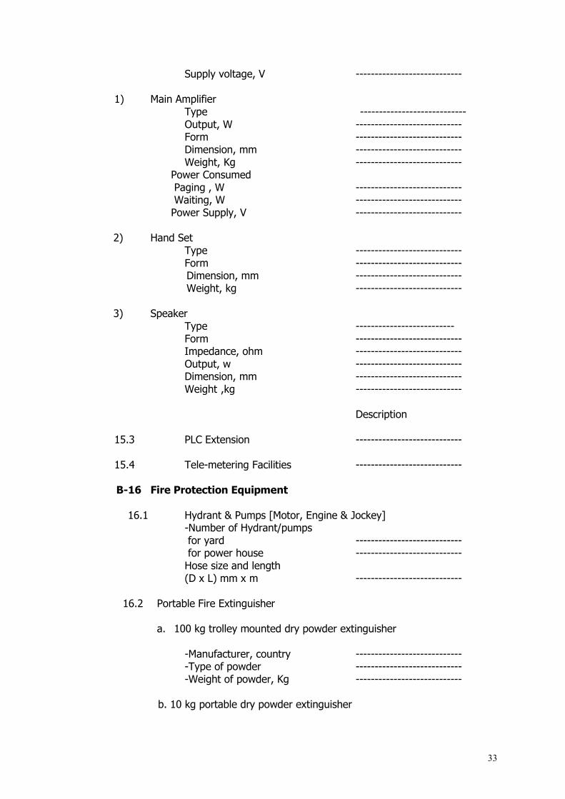
Supply voltage, V ---------------------------- 1) Main Amplifier Type ---------------------------- Output, W ---------------------------- Form ---------------------------- Dimension, mm ---------------------------- Weight, Kg ----------------------------
Power Consumed Paging , W ---------------------------- Waiting, W ---------------------------- Power Supply, V ----------------------------
2) Hand Set Type ----------------------------
Form ---------------------------- Dimension, mm ---------------------------- Weight, kg ---------------------------- 3) Speaker
Type -------------------------- Form ---------------------------- Impedance, ohm ---------------------------- Output, w ---------------------------- Dimension, mm ---------------------------- Weight ,kg ---------------------------- Description 15.3 PLC Extension ---------------------------- 15.4 Tele-metering Facilities ---------------------------- B-16 Fire Protection Equipment 16.1 Hydrant & Pumps [Motor, Engine & Jockey] -Number of Hydrant/pumps for yard ----------------------------
for power house ---------------------------- Hose size and length (D x L) mm x m ----------------------------
16.2 Portable Fire Extinguisher
a. 100 kg trolley mounted dry powder extinguisher -Manufacturer, country ----------------------------
-Type of powder ---------------------------- -Weight of powder, Kg ----------------------------
b. 10 kg portable dry powder extinguisher

34
-Manufacturer, country ---------------------------- -Type of powder ---------------------------- -Weight of powder, Kg ---------------------------- c. 5 kg portable gas extinguisher -Manufacturer, country ---------------------------- -Type of powder ---------------------------- -Weight of gas , Kg ----------------------------
16.3 Auto-Release CO2 Fire Extinguishing System
-Manufacturer, country ---------------------------- -Type of powder ----------------------------
-System Description ----------------------------
16.4 Fire detection Equipment -Manufacturer, country ----------------------------
-Type of Equipment ---------------------------- -Weight of panel, Kg ----------------------------
16.5 Transformer Water Deluge, Ref. No. ----------------------------
B-17 Civil Work and Building Works
17.1 Standards and Codes to be used in design and construction No. Work Item Standard and Codes 1. Filling Works ----------------------------------- 2. Foundation Works ---------------------------------- 3. Piling ---------------------------------- 4. Steel Sheet Piling Wall ---------------------------------- 5. Concrete Works ---------------------------------- 6. Reinforcement Works ---------------------------------- 7. Structural Steel Works ---------------------------------- 8. Road ---------------------------------- 9. Brickwork ---------------------------------- 10. Painting ---------------------------------- 11. Lighting and Power Supply ---------------------------------- 12. Air Conditioning System ---------------------------------- 13. Plumbing ---------------------------------- 14. ------------------------------- ---------------------------------- 15. ------------------------------- ----------------------------------
17.2 Concrete
1) Proposed Materials -Standards: (i) Cement ---------------------------------- (ii) Aggregates ----------------------------------
(iii) Concrete Admixture ---------------------------------- (iv) Reinforcement ---------------------------------- (v) Other ----------------------------------

35
2) Proposed Manufacturers/Source/Quarries (i) Cement ---------------------------------- (ii) Aggregates ----------------------------------
(iii) Concrete Admixture ---------------------------------- (iv) Reinforcement ----------------------------------
(v)Other ----------------------------------
3) Compressive Strength of Concrete at 28th Day 1) Engine generator foundation Kg/cm2 ---------------------------- 2) Supper-structure Kg/cm2 ----------------------------- 3) pile Kg/cm2 ---------------------------------- 4)Concrete pavement ---------------------------------- 5) ----------------------- ---------------------------------- 6) ----------------------- ----------------------------------
17.3 Piling and Subsoil Improvement
17.3.1 Piling
1) Type of foundation pile ---------------------------------- a) Diameter/cross section and length, D= --------------------------m
L= ---------------------------m b) Allowable working load of a pile, Kg -----------------------------
c) Method of driving in Piles ------------------------------ d) Piling Plant ------------------------------ e) Method of Jointing Piles ------------------------------ f) Name of structures, equipment and buildings to be applied ------------------------------
2) Type of foundation pile a) Diameter/cross section and length, D= ---------------------------------- m L= ----------------------------------- m b) Allowable working load of a pile, Kg ------------------------------ c) Method of driving in Piles ------------------------------ d) Piling Plant ------------------------------ e) Method of Jointing Piles ------------------------------ f) Name of structures, equipment and buildings to be applied ------------------------------
3) Type of foundation pile a) Diameter/cross section and length, D= ------------------------------m L= ------------------------------m
b) Allowable working load of a pile, Kg ------------------------------ c) Method of driving in Piles ------------------------------
d) Piling Plant ---------------------------- e) Method Of Jointing Piles ------------------------------ f) Name of structures, Equipment and buildings
to be applied ------------------------------
17.3.2 Subsoil Improvement (if any)

36
1) Method of subsoil improvement
2) Expected allowable bearing capacity of subsoil
(After improvement) ----------------------------Kg/m2
3) Name of structures, equipment and buildings to be applied ------------------------------
17.4 Type and Strength of Steel Sheet Piling Wall
1) Type of Sheet Pile 2) Length of a Pile, m ------------------------------ 3) Width of a Pile, mm ------------------------------ 4) Yield Point, Kg/cm2 ------------------------------ 5) Ultimate Tensile strength, Kg/cm2 ------------------------------ 6) Supplier ------------------------------ 7) Specification of tie rods Materials ------------------------------ Diameter, mm ------------------------------ Length of a tie rod, m ------------------------------ Interval, m ------------------------------
17.5 Structure Steel Works 1) Grades of Steel 2) Suppliers of Steel, Bolts & Fasteners 3) Methods of Welding 4) Corrosion Protection
(i) Method and Materials (ii) Place of preparation 5) Proposed Coatings (i) Type of Product (ii) Manufacturer (iii) Dry Film Thickness (iv) Means of application (v) Place of application (vi) Colour 6) Yield Point 7) Ultimate Tensile Strength
17.6 Engine Generator, EDG., Transformers, Switchgears etc. 1) Weight of machine Engine, Kg ----------------------------- Generator, Kg -------------------------- Em. Diesel Gen set., kg ----------------------------- HFO storage tank kg ------------------------------ LDO storage tank kg ------------------------------ HFO daily tank kg ------------------------------ Unit Transformer (15/230kV), kg ------------------------------- Aux. Transformer (15/ 6.6 kV), kg ------------------------------ Station Transformer (6.6/ 0.415 kV), kg ------------------------------ Others, kg ------------------------------
37
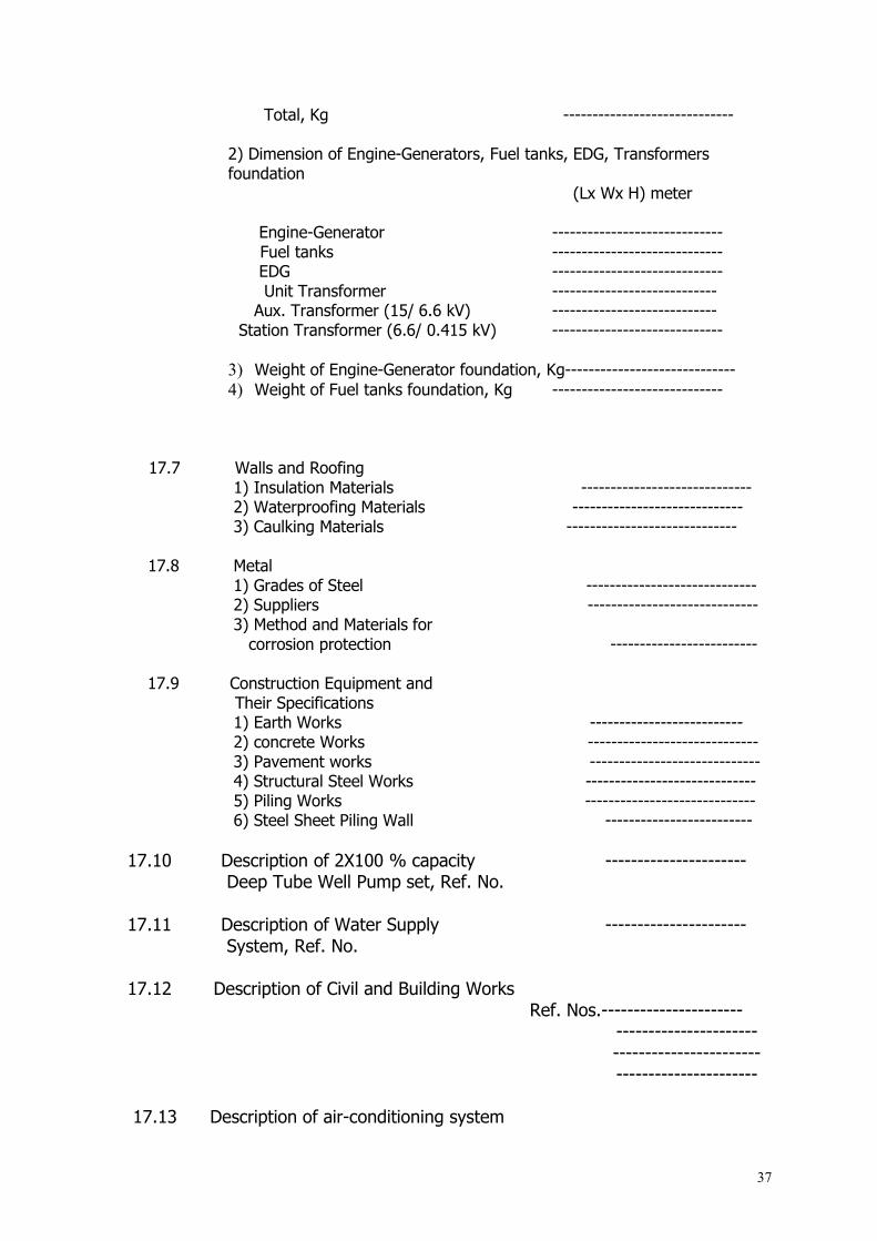
Total, Kg -----------------------------
2) Dimension of Engine-Generators, Fuel tanks, EDG, Transformers foundation (Lx Wx H) meter
Engine-Generator ----------------------------- Fuel tanks ----------------------------- EDG ----------------------------- Unit Transformer ---------------------------- Aux. Transformer (15/ 6.6 kV) ---------------------------- Station Transformer (6.6/ 0.415 kV) -----------------------------
3) Weight of Engine-Generator foundation, Kg----------------------------- 4) Weight of Fuel tanks foundation, Kg -----------------------------
17.7 Walls and Roofing 1) Insulation Materials ----------------------------- 2) Waterproofing Materials ----------------------------- 3) Caulking Materials -----------------------------
17.8 Metal
1) Grades of Steel ----------------------------- 2) Suppliers ----------------------------- 3) Method and Materials for
corrosion protection -------------------------
17.9 Construction Equipment and Their Specifications
1) Earth Works -------------------------- 2) concrete Works ----------------------------- 3) Pavement works ----------------------------- 4) Structural Steel Works ----------------------------- 5) Piling Works -----------------------------
6) Steel Sheet Piling Wall -------------------------
17.10 Description of 2X100 % capacity ---------------------- Deep Tube Well Pump set, Ref. No. 17.11 Description of Water Supply ---------------------- System, Ref. No. 17.12 Description of Civil and Building Works Ref. Nos.---------------------- ---------------------- ----------------------- ---------------------- 17.13 Description of air-conditioning system

38
for the buildings. Ref No.----------------------- B - 18 Environmental Impact. (a) Air Emissions Levels. With regard to project air emissions, please fill out the following table: Emission Percent Removal
Efficiency at 100% Capacity
100% Capacity
75% Capacity
50% Capacity
NOx ----------------------- ----------ppmv ----------ppmv ----------ppmv --------------------- ------- ib/hr ------- ib/hr ------- ib/hr --------------------- --------- g/kj -------- g/kj -------- g/kj ---------------------- ------- m9/m3 ------m9/m3 ------m9/m3 CO2 ----------------------- ------- ppmv ------ppmv ------ppmv ----------------------- --------- ib/hr -------- ib/hr -------- ib/hr ----------------------- --------- g/kj --------- g/kj --------- g/kj ----------------------- --------m9/m3 ------ m9/m3 ------ m9/m3 CO ------------------------ ----------ppmv ----------pmv ----------pmv ------------------------ ------------ib/hr -----------ib/hr -----------ib/hr ------------------------ -------------g/kj ------------g/kj ------------g/kj ------------------------ ---------m9/m3 --------m9/m3 --------m9/m3 Air Toxics (list)
------------------------
ppm is defined as volumetric parts per million at 15% O2 (b) Effluent Discharge P4 -------mg/e Cr ----------- ---------------mg/e BOD -------mg/e Cu---------- ----------mg/e COD --------mg/e Fe----------- ------------mg/e TSS --------mg/e Ni----------- ----------mg/e PO4 ---------mg/e Zr----------- ----------mg/e SO4 ---------mg/e Ac----------- ----------mg/e NH3 ----------mg/e Cd---------- ----------mg/e CL
----------mg/e Pb----------- ----------mg/e
39
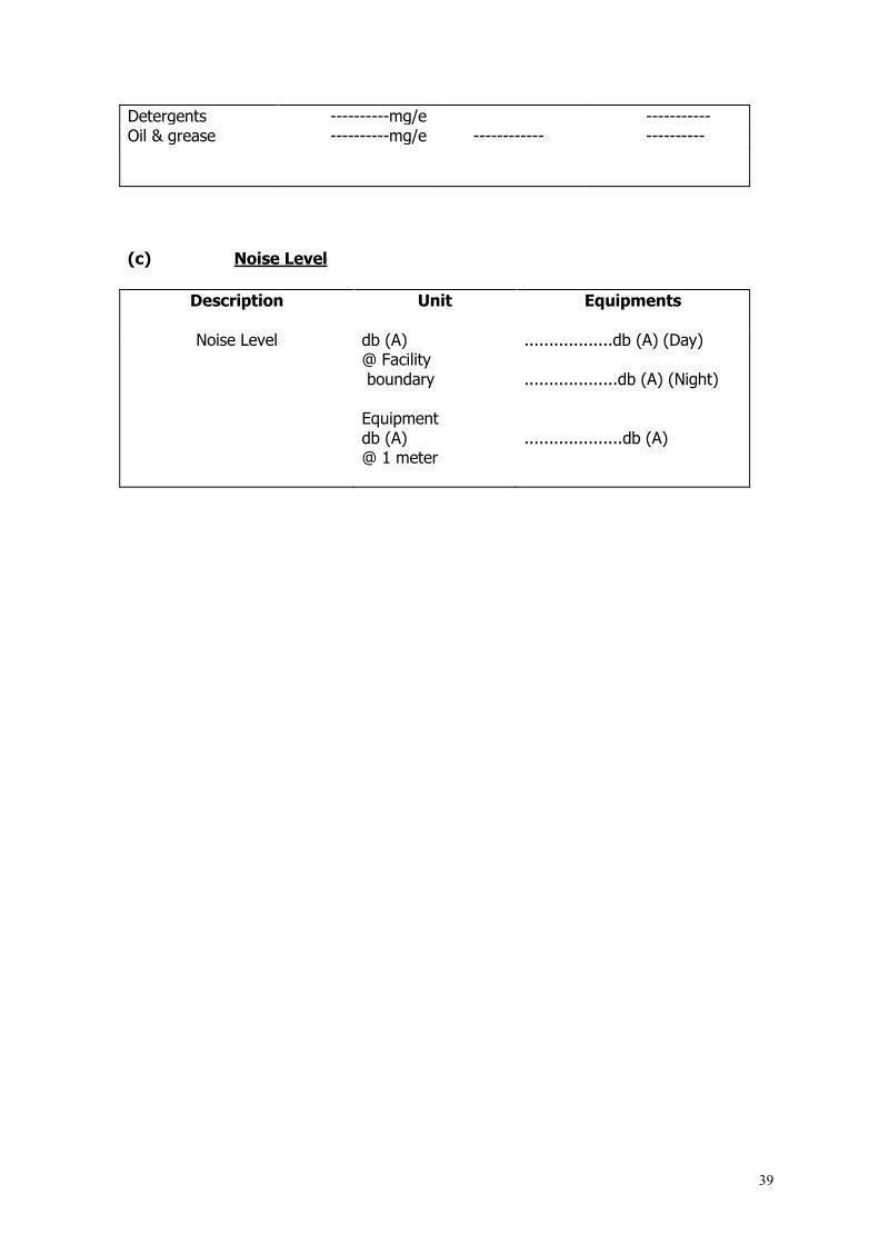
Detergents ----------mg/e ----------- Oil & grease ----------mg/e ------------ ----------
(c) Noise Level
Description Unit Equipments
Noise Level db (A)
@ Facility boundary
..................db (A) (Day)
...................db (A) (Night)
Equipment db (A) @ 1 meter
....................db (A)
40
SCHEDULE-C
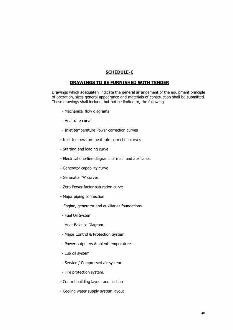
DRAWINGS TO BE FURNISHED WITH TENDER Drawings which adequately indicate the general arrangement of the equipment principle of operation, sizes general appearance and materials of construction shall be submitted. These drawings shall include, but not be limited to, the following.
- Mechanical flow diagrams
- Heat rate curve
- Inlet temperature Power correction curves
- Inlet temperature heat rate correction curves
- Starting and loading curve
- Electrical one-line diagrams of main and auxiliaries
- Generator capability curve
- Generator "V' curves
- Zero Power factor saturation curve
- Major piping connection
-Engine, generator and auxiliaries foundations - Fuel Oil System - Heat Balance Diagram. - Major Control & Protection System. - Power output vs Ambient temperature - Lub oil system - Service / Compressed air system - Fire protection system.
- Control building layout and section
- Cooling water supply system layout

41
- Exhaust heat recovery sytem
- No load saturation curve
- Synchronous impedance curve
- Generator unit equipment arrangement
- Layout plan of central control room
- General arrangement of the switchyard
- Foundation, loading and support information
- Dimensioned Outline drawing Of major equipment offered
- Detail drawings and descriptions providing a complete
- Understanding of the equipment offered
- Other drawings specified in the Specification.
42
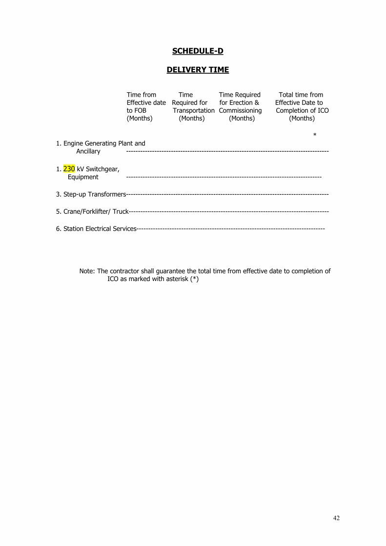
SCHEDULE-D
DELIVERY TIME Time from Time Time Required Total time from Effective date Required for for Erection & Effective Date to to FOB Transportation Commissioning Completion of ICO (Months) (Months) (Months) (Months)
* 1. Engine Generating Plant and Ancillary --------------------------------------------------------------------------------------
1. 230 kV Switchgear,
Equipment -----------------------------------------------------------------------------------
3. Step-up Transformers--------------------------------------------------------------------------------------
5. Crane/Forklifter/ Truck-------------------------------------------------------------------------------------
6. Station Electrical Services--------------------------------------------------------------------------------
Note: The contractor shall guarantee the total time from effective date to completion of
ICO as marked with asterisk (*)

43
SCHEDULE - E
TOOLS AND APPLIANCES The Tenderer shall list below all special tools and equipment for maintenance, which will be supplied and included in total Contract Price. Contractor shall not be permitted to use
any equipment/ machinery/ tools, which are to be supplied against the Contract. No. Description Q'ty
Note: The Tenderer shall attach additional sheets as required.

44
SCHEDULE – F
DEVIATIONS FROM SPECIFICATIONS
The following is a list of deviations from Tender Documents
Clause No.
and
Page No.
Description and Reference to Documents submitted by
Tender
Note : The Tenderer shall attach additional sheets as required
45
SCHEDULE – G
CIVIL AND BUILDING WORKS
The Tenderer shall be reminded that this is Turnkey Contract in which he is entirely responsible for every aspect. No additional costs will be considered for any item which the Tenderer has overlooked, but which is essential for the proper completion of the project in every respect so that the works fulfil the purpose for which they are required.
If the Board or the Engineer require minor modifications, additions or omissions to the scope of the Civil Works during the period of construction or maintenance, adjustment to the Contract Price will be made on the basis of the rates entered in the following Schedule. The rates entered shall include all costs and expenses involved in the proper construction of the work, including overheads, profits, supervision, accommodation, insurances, transport, duties, all risks, liabilities or obligations etc. but excluding design costs, which are covered by a separate item. The rates will be used to evaluate Board’s or Engineer’s minor modifications, omissions or additions to the works. Rates for any item not included shall be based on those quoted or analogous thereto.

46
Item Description Unit Rate Taka
1. 2. 3. 4. 5. 6. 7.
Foundation Piling 1) Mobilisation and Demobilisation
(items shall be specified) 2) Form of pile type and capacity stated :
Type : Capacity :
Excavation 1) Excavate to reduce level and remove and deposit
where directed on Site – include for timbering, de-watering, etc (measured net sizes as drawing)
2) Excavate to form pit , base or trench as previously described.
3) Additional excavation beyond net sizes for working space to fix and remove formwork and to backfill
Concrete work Unreinforced ( grade of concrete shall be specified ) ------------------------------------------------ ------------------------------------------------ ------------------------------------------------ Reinforced Concrete ( grade of concrete shall be specified ) ------------------------------------------------ ----------------------------------------------- ----------------------------------------------- Reinforcement 1) 16 mm diameter and upward mild steel bar or round
reinforcement hooked, bent and fixed including and necessary tying wire
2) 12 mm diameter as previously described 3) 10 mm diameter and ditto as previously described 4) Fabric reinforced weighing 4 Kg per square meter,
including fixing 5) Extra over mild steel rates for high tensile
reinforcement (all sizes) Formwork
1) To sides of foundations, bases, etc 2) To sides and soffits of beam 3) To wall
Structural Steelwork (grades of structure shall be specified) --------------------------------------------- --------------------------------------------- ---------------------------------------------
linear, m m3
m3
m3
m3 m3 m3
m3
m3
m3
Kg Kg Kg m2 Kg m2
m2
m2
1000x Kg
47
SCHEDULE - H
LIST OF SUBCONTRACTORS
The following is a list of subcontractors the Tenderer proposes to employ for supply of materials and equipment and for erection and civil works
No.
Description of part or equipment making reference to specifications
Subcontractors full address
Note : The Tenderer shall attach additional sheets as required

48
SCHEDULE - I
DESCRIPTION OF TRAINING PROGRAMME
Details of Training programme including curriculum and Training aid to be used

49
SCHEDULE - J
MOBILISATION AND DEMOBILISATION SCHEDULE FOR CONSTRUCTION
EQUIPMENT
The following is the specification, numbers, purpose of use and phasing for the
mobilisation and demobilisation of construction equipment to be used on the Contract.

50
SCHEDULE - K
METHOD OF TRANSPORTATION AND UNLOADING
The following is a description of the Contractor’s method for transportation to Site and
unloading and installation at Site of the equipment for the Works.

51
SCHEDULE - L
LIST OF MANUFACTURER
The following is a list of manufacturer the Tenderer proposes to buy materials and equipment and for erection and commissioning
No. Description of part or equipment
Manufacturer name
Manufacturer full address
Note : The Tenderer shall attach additional sheets as required

52
SCHEDULE - M
LIST OF SPARE PARTS
The following is a list of spare parts the Tenderer proposes for the life time (20 years) of the plant.
53
BPDB-RPCL POWERGEN LTD.
TENDER DOCUMENT
FOR
CONSTRUCTION OF MIESARAI 150 MW (±10%) (HFO/GAS) POWER PLANT PROJECT.
VOLUME 2 OF 2 (PART A+PART B)
PART A - TECHNICAL REQUIREMENTS
PART B - TECHNICAL PARTICULARS
OCTOBER- 2016

54


