One Source…Many Solutions…One Purpose2008 SCR User’s Group Conference
Copyright © 2008 Babcock Power Inc. All rights reserved.www.babcockpower.com
11/
Babcock Power Inc.
One Source Many Solutions One Purpose
How Does An SCR Work?
Presented by:
Bill Medeiros
2008 SCR User’s Group Conference
Copyright © 2008 Babcock Power Inc. All rights reserved. www.babcockpower.com
Basic SCR Chemistry
NOX NH3
N2 H2O
4 NO + 4 NH3 + O2 4 N2 + 6 H2O
7 N2 + 12 H2O6 NO2 + 8 NH3
Undesirable side reactions
SO2 + 1/2 O2
NH3 + SO3 + H2O
SO3
NH4 HSO4
Basic reaction equations
Typical coal flue gas95% NO & 5% NO2
2 NO2 + O2 + 4 NH3 3 N2 + 6 H2O
2008 SCR User’s Group Conference
Copyright © 2008 Babcock Power Inc. All rights reserved. www.babcockpower.com
Basic SCR Chemistry
2008 SCR User’s Group Conference
Copyright © 2008 Babcock Power Inc. All rights reserved. www.babcockpower.com
SCR Reactor Configuration
High Dust
Low Dust
Tail End
2008 SCR User’s Group Conference
Copyright © 2008 Babcock Power Inc. All rights reserved. www.babcockpower.com
SCR Reactor Configuration
High Dust Arrangement
2008 SCR User’s Group Conference
Copyright © 2008 Babcock Power Inc. All rights reserved. www.babcockpower.com
SCR Reactor Between
Hot ESP and Air Heater
SCR Reactor Configuration
Low Dust Arrangement
2008 SCR User’s Group Conference
Copyright © 2008 Babcock Power Inc. All rights reserved. www.babcockpower.com
SCR Reactor Configuration
Tail End Arrangement
2008 SCR User’s Group Conference
Copyright © 2008 Babcock Power Inc. All rights reserved. www.babcockpower.com
SCR Reactor Configuration
In Duct Arrangement
2008 SCR User’s Group Conference
Copyright © 2008 Babcock Power Inc. All rights reserved. www.babcockpower.com
2008 SCR User’s Group Conference
Copyright © 2008 Babcock Power Inc. All rights reserved. www.babcockpower.com
SCR Configurations
SCR BypassOTAG Operation Only
Start Up
SCR Low Load Temperature Control (High Dust SCR)Economizer Bypass
Bypass Damper Only
Bypass Damper and Backpressure Damper
Economizer Heat Transfer Surface Reduction
Water Bypass
In-Duct Gas Burners
Steam Bypass
2008 SCR User’s Group Conference
Copyright © 2008 Babcock Power Inc. All rights reserved. www.babcockpower.com
Boiler Startup Bypass
Econ. FurnRoof
& CP PSH SSH
HPT
RH
#8 Htr. #7 Htr.
Flash Tank
Cond.
#6 Htr.
220
Valves
207
Valves
DEA
BFP
242
Valve
2008 SCR User’s Group Conference
Copyright © 2008 Babcock Power Inc. All rights reserved. www.babcockpower.com
Static Mixers – Delta Wings
2008 SCR User’s Group Conference
Copyright © 2008 Babcock Power Inc. All rights reserved. www.babcockpower.com
Ammonia Flow Control•Adjusted based on testing
2008 SCR User’s Group Conference
Copyright © 2008 Babcock Power Inc. All rights reserved. www.babcockpower.com
Ammonia Injection & Flue Gas Mixing
PLANT 3
Burner NOx Test 1
300
350
400
450
500
550
600
0 20 40 60 80 100
Width, ft.
NO
x, p
pm
Series1
Series2
Series3
Series4
Series5
Series6
Inlet variations of
flue gas
composition
Load and burner
group dependent
Mix prior to
ammonia injection
2008 SCR User’s Group Conference
Copyright © 2008 Babcock Power Inc. All rights reserved. www.babcockpower.com
Mixing Prior to Ammonia Injection
Gas Flow
from Boiler
2008 SCR User’s Group Conference
Copyright © 2008 Babcock Power Inc. All rights reserved. www.babcockpower.com
Large Particle Ash (LPA)
LPA Properties
Size >4.0 mm
Density 0.7 to 1.25 g/cc
Sphericity 0.7 to 0.99
Coefficient of Restitution 0.15 to 0.2
Screen Design Important
Pluggage
Erosion
2008 SCR User’s Group Conference
Copyright © 2008 Babcock Power Inc. All rights reserved. www.babcockpower.com
LPA Screen Design
Design and Modeling
CFD Modeling
Industry Coated Screens
Experience From Past
Soot Blowers
Low Velocity
Low Pressure Loss
2008 SCR User’s Group Conference
Copyright © 2008 Babcock Power Inc. All rights reserved. www.babcockpower.com
Catalyst - Types
• Honeycomb
• Corrugated
• Plate
2008 SCR User’s Group Conference
Copyright © 2008 Babcock Power Inc. All rights reserved. www.babcockpower.com
Catalyst Manufacture
2008 SCR User’s Group Conference
Copyright © 2008 Babcock Power Inc. All rights reserved. www.babcockpower.com
2008 SCR User’s Group Conference
Copyright © 2008 Babcock Power Inc. All rights reserved. www.babcockpower.com
Catalyst Vendors
Vendor Name Catalyst Type Fuel Type
Argillon (Siemens) Honeycomb Gas, Oil, Coal
Plate Coal High Dust
KWH Honeycomb Gas, Oil, Coal – Low Dust, Coal High Dust
Cormetech Honeycomb Gas, Oil, Coal – Low Dust, Coal High Dust
Haldor Topsoe Corrugated Gas, Oil, Coal – Low Dust, Coal High Dust
Ceram Honeycomb Gas, Oil, Coal – Low Dust, Coal High Dust
Nippon Shokubai Honeycomb Gas, Oil, Coal – Low Dust, Coal High Dust
Hitz America Corrugated Gas, Oil Limited Coal Experience
Hitachi America Plate Gas, Oil, Coal – Low Dust, Coal High Dust
2008 SCR User’s Group Conference
Copyright © 2008 Babcock Power Inc. All rights reserved. www.babcockpower.com
Riley Standard Module
2008 SCR User’s Group Conference
Copyright © 2008 Babcock Power Inc. All rights reserved. www.babcockpower.com
Catalyst Design Parameters
Fuels
Initial catalyst life (hours of initial operation)
Maximum ammonia slip
Flue-gas conditions
SO2 to SO3 conversion rate (initial – final)
NOx reduction
Catalyst layout (module size and number of modules per layer)
Flue-gas distribution across top layer of catalyst
Geometry – arrangement
2008 SCR User’s Group Conference
Copyright © 2008 Babcock Power Inc. All rights reserved. www.babcockpower.com
Catalyst Pitch Selection
• High dust honeycomb (bituminous)
– 7 mm pitch - 500 m2/m3
• High dust honeycomb (sub-bituminous)
– 8.2 mm pitch - 420 m2/m3
• Low dust
– 5.9 mm pitch - 580 m2/m3
• Plate
– 5.6 pitch - 350 m2/m3
2008 SCR User’s Group Conference
Copyright © 2008 Babcock Power Inc. All rights reserved. www.babcockpower.com
Catalyst – Fuel Impact
Major Considerations
Sulfur content (ammonium salts)
Ash loading
Arsenic
CaO
Vanadium (‘pet’ coke, heavy oils)
Other trace elements
2008 SCR User’s Group Conference
Copyright © 2008 Babcock Power Inc. All rights reserved. www.babcockpower.com
Catalyst – Deactivation
2008 SCR User’s Group Conference
Copyright © 2008 Babcock Power Inc. All rights reserved. www.babcockpower.com
Arsenic Effect on Catalyst Life
First noted in wet bottom 100% ash recycling boilers
Poisoning from As2O3 (gaseous)
Reacts with CaO to form non-poisoning Ca3(AsO4)2 (solid)
CaO addition proven in Europe and US
Additional effects
Increased ash loading
Lower SO3 production in boiler
2008 SCR User’s Group Conference
Copyright © 2008 Babcock Power Inc. All rights reserved. www.babcockpower.com
CaO Deactivation MechanismThe deactivation is rate limited by CaO deposition
Step 1CaO is caught on the
catalyst surface
Process is dependent on availability and adhesion of CaO
•Rate controlling process for deactivation•Very slow concentration changes (~104 hours)
CaO
CaO
catalystsurface CaO
active sites
•Fast reaction time (~101 hours)
Step 2
SO3 bonding & diffusion
Process is function of mass transfer and concentration
CaO
active sites
SO3catalystsurface
2008 SCR User’s Group Conference
Copyright © 2008 Babcock Power Inc. All rights reserved. www.babcockpower.com
Step 3
Diffusion and expansion CaO + SO3 CaSO4
Reaction is a function of diffusion rate and SO3 concentration
CaO Deactivation MechanismCaSO4 blocks active deNOx sites on catalyst surface
•Reaction time (~101hours) •Particle expansion of 14%
CaSO4
active sites
catalystsurface
Deactivation: NH3 & NOx can’t reach masked active sites
CaSO4
inactive sites
Step 4
Deactivation is a function of CaOloading over time
active sites
catalystsurface
2008 SCR User’s Group Conference
Copyright © 2008 Babcock Power Inc. All rights reserved. www.babcockpower.com
Catalyst – Minimum Continuous Operating Temperature (Tmcot)
Minimum operating temperature for SCR without
formation of ammonium salts
High partial pressure in catalyst pores
Dew point in pores >> Dew point in duct
Tmcot = f(SO3,NH3,H2O)
Excess of NH3 and H2O at catalyst inlet
SO3 from boiler limiting factor
↑S in Fuel, ↑Tmcot
2008 SCR User’s Group Conference
Copyright © 2008 Babcock Power Inc. All rights reserved. www.babcockpower.com
Flow Model Objectives
NH3/NOX distribution @ 1st layer
Gas velocity distribution
Temperature distribution
Gas flow angle @ 1st layer
Dust distribution
System pressure loss
Air heater requirements
Influence testing
Catalyst Requirements
2008 SCR User’s Group Conference
Copyright © 2008 Babcock Power Inc. All rights reserved. www.babcockpower.com
Flow Modeling – Model Scales
Gas mixing and design 1:40 to 1:35
Larger scale (smaller model) allows for faster design
changes
Experience with transition between larger scale to
smaller scale to full scale
Dust layout 1:16 to 1:12
Necessary to satisfy the Barth number
2008 SCR User’s Group Conference
Copyright © 2008 Babcock Power Inc. All rights reserved. www.babcockpower.com
SCR Flow Models
2u
pEu
ρ∆
=mm
gas
Dd
lCBa
ρ
ρ=
νbu
=Re
2008 SCR User’s Group Conference
Copyright © 2008 Babcock Power Inc. All rights reserved. www.babcockpower.com
SCR Flow Model
2008 SCR User’s Group Conference
Copyright © 2008 Babcock Power Inc. All rights reserved. www.babcockpower.com
Multiple Injection Points
2008 SCR User’s Group Conference
Copyright © 2008 Babcock Power Inc. All rights reserved. www.babcockpower.com
SCR Dust Model
2008 SCR User’s Group Conference
Copyright © 2008 Babcock Power Inc. All rights reserved. www.babcockpower.com
Catalyst – Cleaning
Steam Sootblowers
Requires controlled steam quality, dry steam
Rake type sootblower
Required for high ash concentration (> 20 g/Nm3)
Sonic Horns
Compressed air requirements typical of service air
Low air quantities required
Continuous operation
U.S. application and popularity increasing
2008 SCR User’s Group Conference
Copyright © 2008 Babcock Power Inc. All rights reserved. www.babcockpower.com
Anhydrous Ammonia
Hazardous chemical
governed by codes
Aqueous Ammonia
Concentration based
codes, maybe changed in
future
Urea Based Ammonia
Safe storage, more equipment and complex
Ammonia Systems
2008 SCR User’s Group Conference
Copyright © 2008 Babcock Power Inc. All rights reserved. www.babcockpower.com
Ammonia System – Safety Codes & Standards
3 Levels of alarm and detection
35 ppm (Lights): Threshold Limit Value – Short Term
Exposure Limit (TLV-STEL) by the American Congress of Governmental Industrial Hygienists
(ACGIH)
50 ppm (Lights & Horns): OSHA 8 hour exposure limit
300 ppm (Lights, Horns, & E-Stop): Immediately Dangerous to Life or Health (IDLH) limit from the
National Institute for Occupational Safety and Health (NIOSH) and OSHA
2008 SCR User’s Group Conference
Copyright © 2008 Babcock Power Inc. All rights reserved. www.babcockpower.com
Ammonia InjectionAnhydrous
Vaporizers
Direct injection
Dilution air, 5% by volume
Aqueous
Vaporizers
Direct injection
Urea
Direct injection
Dilution air, 5% by volume
2008 SCR User’s Group Conference
Copyright © 2008 Babcock Power Inc. All rights reserved. www.babcockpower.com
Ammonia System – Anhydrous
99.5% NH3, 0.5% H2O
Method of vaporization
Flooded vaporizer with storage tank
Level controlled vaporizer
Direct injection
Dilution air
5% ammonia by volume (lower explosive limit 15%)
Typically 175 to 300°F at duct injection location
2008 SCR User’s Group Conference
Copyright © 2008 Babcock Power Inc. All rights reserved. www.babcockpower.com
Ammonia System – Anhydrous Codes
OSHA 29 CFR 1910.111, Storage and Handling of
Anhydrous Ammonia
ANSI/CGA K61.1, Safety Requirements for the
Storage and Handling of Anhydrous Ammonia
ASME B31.3, Process Piping
2008 SCR User’s Group Conference
Copyright © 2008 Babcock Power Inc. All rights reserved. www.babcockpower.com
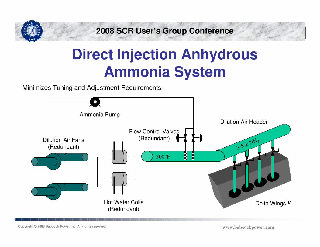
Direct Injection Anhydrous Ammonia System
Hot Water Coils(Redundant)
Flow Control Valves(Redundant)
Ammonia Pump
Dilution Air Header
Delta WingsTM
3-5% NH 3
300°F
Minimizes Tuning and Adjustment Requirements
Dilution Air Fans(Redundant)
2008 SCR User’s Group Conference
Copyright © 2008 Babcock Power Inc. All rights reserved. www.babcockpower.com
Ammonia System – Anhydrous Equipment Selection
Storage Tanks
-28°F to site maximum design temperature
250 psig design pressure minimum
Code ASME Section VIII vessel
Excess flow valves on all nozzles
Two methods of level indication
2008 SCR User’s Group Conference
Copyright © 2008 Babcock Power Inc. All rights reserved. www.babcockpower.com
Ammonia System – Anhydrous Equipment Selection
Transfer pumps
Seal-less pump design
Magnetic drive
Canned pump
Suction pipe design
Recirculation vs. injection rate
2008 SCR User’s Group Conference
Copyright © 2008 Babcock Power Inc. All rights reserved. www.babcockpower.com
Ammonia System – Anhydrous Equipment Selection
Piping / Valves
No copper, brass, or galvanized steel
Conforming to ASME B31.3, Process Piping
Minimum number of threaded connections
Hydrostatic relief required on all isolatable sections
Leak / pressure tests of system prior to service
All instrumentation suitable for anhydrous ammonia
2008 SCR User’s Group Conference
Copyright © 2008 Babcock Power Inc. All rights reserved. www.babcockpower.com
Ammonia System – Anhydrous Equipment Selection
Truck / Railcar Unloading
Snappy Joes and breakaways to protect ammonia
equipment
DOT Regulations to be followed
Railroad unloading procedures per ammonia / railroad supplier
Truck unloading procedures per ammonia / truck supplier
2008 SCR User’s Group Conference
Copyright © 2008 Babcock Power Inc. All rights reserved. www.babcockpower.com
Ammonia System – Aqueous
3 Common concentrations
9% Ammonia
19% Ammonia
29% Ammonia
No definitive codes or standards
Sound engineering practices need to be applied
2008 SCR User’s Group Conference
Copyright © 2008 Babcock Power Inc. All rights reserved. www.babcockpower.com
Ammonia System – Aqueous Equipment Selection
Storage tanks
ASME Section VIII
API 610
Pumps same as anhydrous
Pipes and valves
No definitive codes or standards
Typical ASME B31.1 acceptable
Unloading by truck only
2008 SCR User’s Group Conference
Copyright © 2008 Babcock Power Inc. All rights reserved. www.babcockpower.com
Dual Fluid Nozzle Injector
2008 SCR User’s Group Conference
Copyright © 2008 Babcock Power Inc. All rights reserved. www.babcockpower.com
Ammonia System – Urea
Multiple conversion technologies available
Typically delivered in dry or liquid form
Best stored on site as liquid
No definitive codes or standards
Good engineering practices need to be applied
Heat tracing critical
Urea quality issues
2008 SCR User’s Group Conference
Copyright © 2008 Babcock Power Inc. All rights reserved. www.babcockpower.com
Urea Systems (Others)
• FuelTech
– Thermal breakdown of urea by gas
combustion
– High gas use if ambient air is used
2008 SCR User’s Group Conference
Copyright © 2008 Babcock Power Inc. All rights reserved. www.babcockpower.com
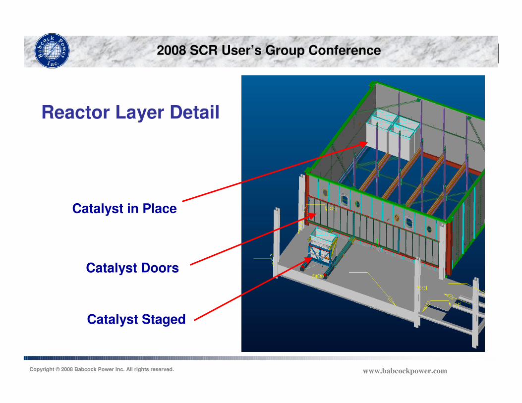
Catalyst in Place
Catalyst Staged
Catalyst Doors
Reactor Layer Detail
2008 SCR User’s Group Conference
Copyright © 2008 Babcock Power Inc. All rights reserved. www.babcockpower.com
Domestic Shipment of Catalyst
2008 SCR User’s Group Conference
Copyright © 2008 Babcock Power Inc. All rights reserved. www.babcockpower.com
Overseas Shipment Containers(Honeycomb Catalyst)
2008 SCR User’s Group Conference
Copyright © 2008 Babcock Power Inc. All rights reserved. www.babcockpower.com
Lifting Catalyst on Hoist
2008 SCR User’s Group Conference
Copyright © 2008 Babcock Power Inc. All rights reserved. www.babcockpower.com
Catalyst in Position for Loading
2008 SCR User’s Group Conference
Copyright © 2008 Babcock Power Inc. All rights reserved. www.babcockpower.com
Catalyst Module Being Pushed into Reactor
2008 SCR User’s Group Conference
Copyright © 2008 Babcock Power Inc. All rights reserved. www.babcockpower.com
Installation of Catalyst Module Seals
2008 SCR User’s Group Conference
Copyright © 2008 Babcock Power Inc. All rights reserved. www.babcockpower.com
Requirements of NOx Measurement Instrumentation for SCR Control
Provide inlet and outlet NOx measurement in ppm for the forward
feed with back trim ammonia injection control loop
Respond quickly to changes in the NOx values to reduce the risk of
over/under feeding ammonia to the process
The ability to service the instrument, including probe in flue gas duct
without removing boiler or SCR from service
2008 SCR User’s Group Conference
Copyright © 2008 Babcock Power Inc. All rights reserved. www.babcockpower.com
Types of Available NOx Measurement Instrumentation
Extractive, extractive systems draw flue gas at temperature from the
system in a heated sample line to the analyzer
Dilution Extractive, dilution extractive system draw flue gas from the
system and dilution the gas with air to lower the concentrations of
SO3, H2O, etc to eliminate the need for heated sample lines to
the analyzer
In Situ, in situ system place the measuring device directly in the flue
gas path
One Source…Many Solutions…One Purpose2008 SCR User’s Group Conference
Copyright © 2008 Babcock Power Inc. All rights reserved.www.babcockpower.com
SCR Performance
11/
2008 SCR User’s Group Conference
Copyright © 2008 Babcock Power Inc. All rights reserved. www.babcockpower.com
Units 1&2 Background
642 MWG CE balanced draft boilers
Eastern bituminous coal
High sulfur (3%)
Fuel oil burned at startup
U2A reagent
Routinely operate at minimum load of
33% MCR
2008 SCR User’s Group Conference
Copyright © 2008 Babcock Power Inc. All rights reserved. www.babcockpower.com
Design Requirements
High NOx removal
92.5% NOx removal
0.045 lb/MBtu outlet
LPA Mitigation
LPA screen
Baffle and deflector plates
Minimum load of 33% MCR with 0.045 lb/MBtu outlet
2008 SCR User’s Group Conference
Copyright © 2008 Babcock Power Inc. All rights reserved. www.babcockpower.com
Guarantees
Guarantees Values
Outlet NOx 0.045 lb/MBtu
Ammonia slip 2 ppmvd
Pressure drop 8.4 iwg
SO2 oxidation rate 0.50%
Ammonia consumption 1260 lb/h
2008 SCR User’s Group Conference
Copyright © 2008 Babcock Power Inc. All rights reserved. www.babcockpower.com
SCR Design Parameters
Parameter Maximum Load Minimum Load
Boiler heat input, MBtu/h 5,800 2,400
Flue gas flow rate, lb/h 5,885,000 3,076,438
Inlet NOx, lb/MBtu 0.6 0.45
Outlet NOx, lb/MBtu 0.045 0.045
Economizer exit gas temperature, oF 700 495
2008 SCR User’s Group Conference
Copyright © 2008 Babcock Power Inc. All rights reserved. www.babcockpower.com
SCR Design Features
Two four layer reactors per unit
Three initially installed layer and one future layer of catalyst
Inlet and outlet NOx analyzers
SCR inlet temperature control (per reactor)
Two double louver economizer bypass dampers
One single louver backpressure damper
Delta Wing™ static mixers with six ammonia injectors
Six sonic horns per installed catalyst layer
2008 SCR User’s Group Conference
Copyright © 2008 Babcock Power Inc. All rights reserved. www.babcockpower.com
SCR Design Features
CFD model
Performed to examine screen location and pressure loss
Baffle location
LPA deflector plate
Identify lowest velocity zone
One LPA screen per reactor
No NOx components supplied screen
Hexagonal perforated plate
Low velocity
Minimize catalyst pluggage
2008 SCR User’s Group Conference
Copyright © 2008 Babcock Power Inc. All rights reserved. www.babcockpower.com
SCR Temperature Control
Maintain SCR inlet temperature at all loads
Economizer bypass provides hot flue gas at low loads
Backpressure damper partially closes to force economizer bypass
2008 SCR User’s Group Conference
Copyright © 2008 Babcock Power Inc. All rights reserved. www.babcockpower.com
SCR Flow Modeling
Two model scales performed
Flow model
1:40 scale
Optimize mixing
Identify performance parameters
Flow model photo courtesy of Ruscheweyh Consult andBalcke Dürr GmbH
2008 SCR User’s Group Conference
Copyright © 2008 Babcock Power Inc. All rights reserved. www.babcockpower.com
SCR Dust Modeling
Dust model
1:15 scale
Verify flow model
Identify particulate settlement
Measure ash distribution at catalyst inlet
Flow model photo courtesy of Ruscheweyh Consult andBalcke Dürr GmbH
2008 SCR User’s Group Conference
Copyright © 2008 Babcock Power Inc. All rights reserved. www.babcockpower.com
SCR Results
Acceptance test results
Reactor 1A full load
42 test ports
NH3/NOx profile
Guarantee of 5% rms
Tested 1.8% rms at 93% NOx removal
2008 SCR User’s Group Conference
Copyright © 2008 Babcock Power Inc. All rights reserved. www.babcockpower.com
SCR Results
Acceptance test results
Reactor 1B full load
42 test ports
NH3/NOx profile
Guarantee of 5% rms
Tested 2.2% rms at 94.6% NOx removal
2008 SCR User’s Group Conference
Copyright © 2008 Babcock Power Inc. All rights reserved. www.babcockpower.com
SCR Results
Reactor 1A Reactor 1B Reactor 1A Reactor 1B
Reactor inlet temperature, oF 667 653 677 675
Inlet NOx , lb/MBtu 0.43 0.59 0.495 0.52
Outlet NOx , lb/MBtu 0.032 0.032 0.043 0.054
NOx removal, % 92.6 94.6 91.3 90.0
Ammonia slip, ppm 0.08 0.11 0.1 <0.1
Ammonia consumption, lb/h 482 657 N/A N/A
Pressure drop, iwg 7.1 7.4 N/A N/A
ParameterMaximum Load Minimum Load
2008 SCR User’s Group Conference
Copyright © 2008 Babcock Power Inc. All rights reserved. www.babcockpower.com
SCR Results(Thirty Day Rolling Average)
0.000
0.020
0.040
0.060
0.080
0.100
0.120
June-07 August-07 September-
07
November-07 January-08 February-08 April-08
Date
Avera
ge N
Ox R
ate
(lb
/mm
Btu
)
2008 SCR User’s Group Conference
Copyright © 2008 Babcock Power Inc. All rights reserved. www.babcockpower.com
SCR Achievements
High Removal Efficiency (> 92.5%)
Low Ammonia Slip (< 2 ppm)
Low SO2 to SO3 Conversion (< 0.5%)
Wide SCR Operating Range (33% to 100%)
Proven Long Term Operation
One Source…Many Solutions…One Purpose2008 SCR User’s Group Conference
Copyright © 2008 Babcock Power Inc. All rights reserved.www.babcockpower.com
SCR Performance Enhancements
11/
One Source…Many Solutions…One Purpose2008 SCR User’s Group Conference
Copyright © 2008 Babcock Power Inc. All rights reserved.www.babcockpower.com
Improved Tuning
2008 SCR User’s Group Conference
Copyright © 2008 Babcock Power Inc. All rights reserved. www.babcockpower.com
South Bay Unit 3Chula Vista, CA
Boiler Manufacturer Riley Stoker
Generator Manufacturer General Electric
Gross Generating Capacity 183 MW
Heat Input 2,145 MMBtu/hr
Operating Date 1964
Fuel
SCR NOx Control
Natural Gas and/or # 6 Oil
March 2001
2008 SCR User’s Group Conference
Copyright © 2008 Babcock Power Inc. All rights reserved. www.babcockpower.com
South Bay Unit 3 SCR Arrangement
2008 SCR User’s Group Conference
Copyright © 2008 Babcock Power Inc. All rights reserved. www.babcockpower.com
South Bay Unit 3 SCR
2008 SCR User’s Group Conference
Copyright © 2008 Babcock Power Inc. All rights reserved. www.babcockpower.com
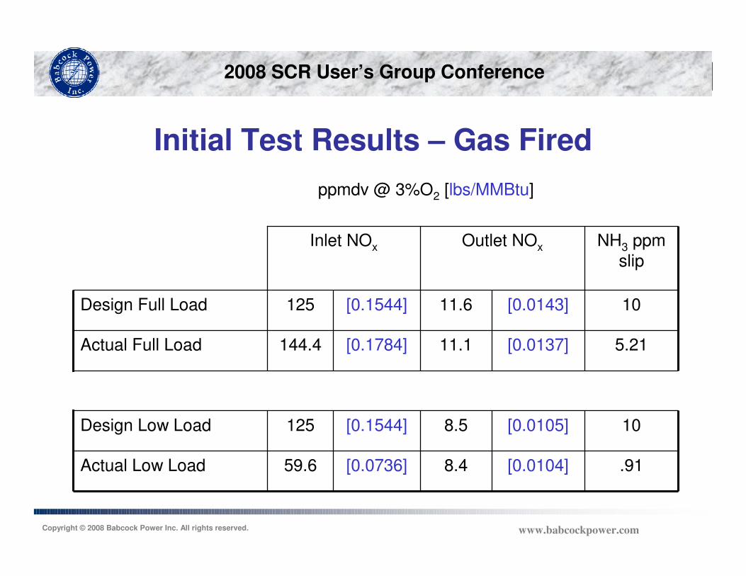
Initial Test Results – Gas Fired
.91[0.0104]8.4[0.0736]59.6Actual Low Load
10[0.0105]8.5[0.1544]125Design Low Load
5.21[0.0137]11.1[0.1784]144.4Actual Full Load
10[0.0143]11.6[0.1544]125Design Full Load
NH3 ppm
slip
Outlet NOxInlet NOx
ppmdv @ 3%O2 [lbs/MMBtu]
2008 SCR User’s Group Conference
Copyright © 2008 Babcock Power Inc. All rights reserved. www.babcockpower.com
Operating History
2001 Acceptance test
2004 Stack tests NH3 slip exceeds California limits
NH3 >> 10.5 ppm
Top to bottom outlet NOx gradient
Inspection: ammonia injection valve plugged
2004 SCR re-tuned NH3 slip 2.2 ppm (high load)
Low load ammonia flow control difficult
2005 Enhanced control system installed
2005 Testing
Ammonia feed control at high/low load
Inlet/outlet NOx profiles
2008 SCR User’s Group Conference
Copyright © 2008 Babcock Power Inc. All rights reserved. www.babcockpower.com
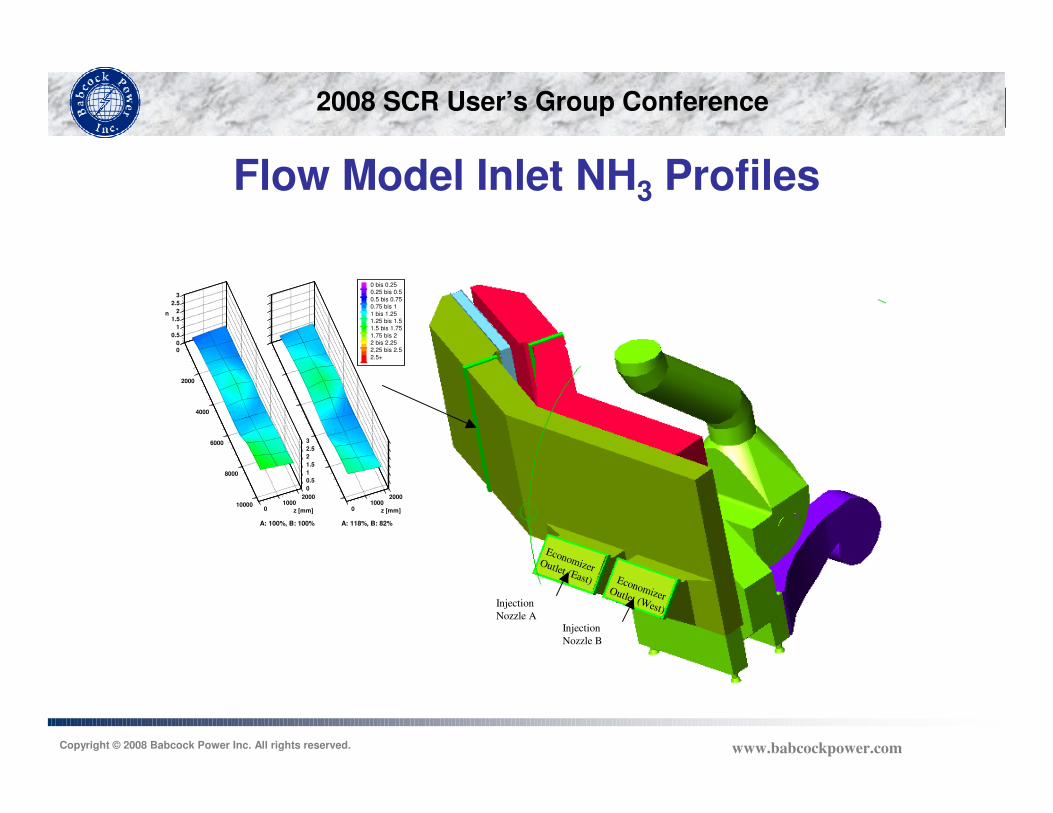
Flow Model Inlet NH3 Profiles
Economizer Outlet (West)
Economizer Outlet (East)
Injection
Nozzle A
Injection
Nozzle B
0
2000
4000
6000
8000
100000
10002000
z [mm]
0
0.5
1
1.5
2
2.5
3
0
0.5
1
1.5
2
2.5
3
n
01000
2000
z [mm]
0 bis 0.250.25 bis 0.5
0.5 bis 0.750.75 bis 1
1 bis 1.251.25 bis 1.51.5 bis 1.75
1.75 bis 22 bis 2.252.25 bis 2.5
2.5+
A: 100%, B: 100% A: 118%, B: 82%
2008 SCR User’s Group Conference
Copyright © 2008 Babcock Power Inc. All rights reserved. www.babcockpower.com
Flow Model Inlet NH3 ProfilesSingle Nozzle Tests
Economizer Outlet (West)
Economizer Outlet (East)
Injection Nozzle A
Injection Nozzle B
0
2000
4000
6000
8000
100000
10002000
z [mm]
0
0.5
1
1.5
2
2.5
3
0
0.5
1
1.5
2
2.5
3
n
01000
2000
z [mm]
0 bis 0.25
0.25 bis 0.5
0.5 bis 0.750.75 bis 1
1 bis 1.25
1.25 bis 1.5
1.5 bis 1.751.75 bis 2
2 bis 2.25
2.25 bis 2.52.5+
Nozzle A Nozzle B
Normalized Inlet Duct Ammonia Distribution
From Each Injection Nozzle
Economizer Outlet (West)
Economizer Outlet (East)
Injection Nozzle A
Injection Nozzle B
Economizer Outlet (West)
Economizer Outlet (East)
Injection Nozzle A
Injection Nozzle B
Economizer Outlet (West)
Economizer Outlet (East)
Injection Nozzle A
Injection Nozzle B
0
2000
4000
6000
8000
100000
10002000
z [mm]
0
0.5
1
1.5
2
2.5
3
0
0.5
1
1.5
2
2.5
3
n
01000
2000
z [mm]
0 bis 0.25
0.25 bis 0.5
0.5 bis 0.750.75 bis 1
1 bis 1.25
1.25 bis 1.5
1.5 bis 1.751.75 bis 2
2 bis 2.25
2.25 bis 2.52.5+
Nozzle A Nozzle B
Normalized Inlet Duct Ammonia Distribution
From Each Injection Nozzle
0
2000
4000
6000
8000
100000
10002000
z [mm]
0
0.5
1
1.5
2
2.5
3
0
0.5
1
1.5
2
2.5
3
n
01000
2000
z [mm]
0 bis 0.25
0.25 bis 0.5
0.5 bis 0.750.75 bis 1
1 bis 1.25
1.25 bis 1.5
1.5 bis 1.751.75 bis 2
2 bis 2.25
2.25 bis 2.52.5+
Nozzle A Nozzle B
Normalized Inlet Duct Ammonia Distribution
From Each Injection Nozzle
2008 SCR User’s Group Conference
Copyright © 2008 Babcock Power Inc. All rights reserved. www.babcockpower.com
Outlet NOx Profiles*June 2004
0 5 10 15 20 25 30
WidthFlow Out of Page
0
5
10
15
20
25
30
Heig
ht (f
t) W
est
0 5 10 15 20 25 30
WidthFlow Out of Page
0
5
10
15
20
25
30
Heig
ht (f
t) W
est
* Testing by FERCo
Test 1, 165 MW Test 8, 158 MW
Avg NH3 slip 2.2 ppm
2008 SCR User’s Group Conference
Copyright © 2008 Babcock Power Inc. All rights reserved. www.babcockpower.com
SCR Control
2008 SCR User’s Group Conference
Copyright © 2008 Babcock Power Inc. All rights reserved. www.babcockpower.com
NOX Measurement
Rea
ctor
Outlet
SCR Outlet NOx Probe Locations
Option 2
Option 1
Economizer Outlet (East)
NOx Probe Location
Economizer Outlet (West)
NOx Probe Location
NOx / O2 Analyzer Shelter Location
(Adjacent to Existing CEMS Building)R
eact
or
Outlet
SCR Outlet NOx Probe Locations
Option 2
Option 1
Economizer Outlet (East)
NOx Probe Location
Economizer Outlet (West)
NOx Probe Location
NOx / O2 Analyzer Shelter Location
(Adjacent to Existing CEMS Building)
SCR Outlet NOx Probe Locations
A-Side (east) B-Side (west)
SCR Outlet NOx Probe Locations
A-Side (east) B-Side (west)
2008 SCR User’s Group Conference
Copyright © 2008 Babcock Power Inc. All rights reserved. www.babcockpower.com
Ammonia Dual RangeFlow Control
0
10
20
30
40
50
60
70
80
90
100
0 100 200 300 400 500
Ammonia Flow, lb/hr
Va
lve
Po
sit
ion
, %
op
en
High Flow Valve(1/2"w /Trim E, CV=0.5) High Flow Valve(1/2"w /Trim F, CV=0.32)
Low Flow Valve(1/2"w /Trim J, CV=0.05)
Full Load Oil
Full Load Gas
Low
Load
East
West
Purge
2008 SCR User’s Group Conference
Copyright © 2008 Babcock Power Inc. All rights reserved. www.babcockpower.com
Outlet NOx Profiles*July 2005
0 5 10 15 20 25 30
Width (ft)Flow Out Of Page
0
5
10
15
20
25
30
Heig
ht (f
t)
West
0 5 10 15 20 25 30
Width (ft)Flow Out Of Page
0
5
10
15
20
25
30
Heig
ht (f
t)
West
0 5 10 15 20 25 30
Width (ft)Flow Out Of Page
0
5
10
15
20
25
30
Heig
ht
(ft)
W
est
East
Manual Control
Automated Control
35 MW
107 MW
140 MW
* Testing by FERCo
2008 SCR User’s Group Conference
Copyright © 2008 Babcock Power Inc. All rights reserved. www.babcockpower.com
Summary
Limited number of NH3 injectors
Clearly defined influence fields for each injector
Demonstrated improved performance with automatic control of injector NH3 flow
2008 SCR User’s Group Conference
Copyright © 2008 Babcock Power Inc. All rights reserved. www.babcockpower.com
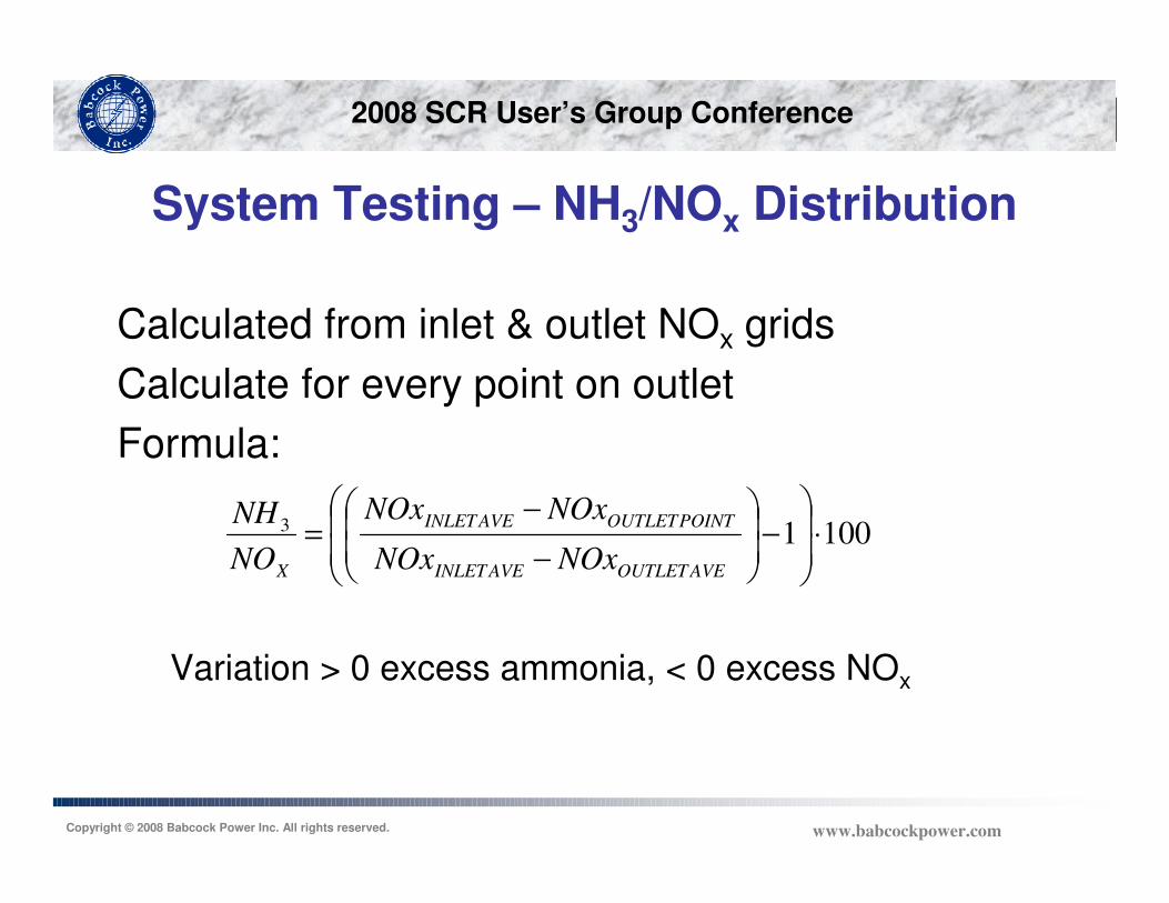
System Testing – NH3/NOx Distribution
Calculated from inlet & outlet NOx grids
Calculate for every point on outlet
Formula:
Variation > 0 excess ammonia, < 0 excess NOx
10013 ⋅
−
−
−=
AVEOUTLETAVEINLET
POINTOUTLETAVEINLET
X NOxNOx
NOxNOx
NO
NH
2008 SCR User’s Group Conference
Copyright © 2008 Babcock Power Inc. All rights reserved. www.babcockpower.com
System Optimization – Influence Testing
Insight into ammonia distribution
Aids in injector tuning
Influences can be simulated in the flow model for
comparison
2008 SCR User’s Group Conference
Copyright © 2008 Babcock Power Inc. All rights reserved. www.babcockpower.com
System Optimization – Influence Testing
5 10 15 20 25 30 35 40 45 50
5
10
15
20
25
30
35
40
45
304
299
305
304
268
321
333
339
312
305
346
371
399
390
373
449
424
422
460
480
518
518
496
508
510
540
531
521
515
514
545
532
527
520
520
557
548
544
539
537
#1#2#3#4#5#6
100%0%0%0%0%0%
5 10 15 20 25 30 35 40 45 50
5
10
15
20
25
30
35
40
45
310
298
308
308
271
329
332
341
307
312
356
366
394
383
377
446
417
425
450
475
516
504
502
499
513
539
526
502
519
522
549
530
531
526
525
563
547
547
547
547
#1#2#3#4#5#6
420422424426428430432434436438440442444446448450452454456458460462464466468470
0%100%0%0%0%0%
Valve 1 Valve 2
2008 SCR User’s Group Conference
Copyright © 2008 Babcock Power Inc. All rights reserved. www.babcockpower.com
Optimization Technique
∑=
=N
j
jiji XKB1
∑=
=M
i
i
avgM
BAMM
1
∑∑
∑=
=
=
−=M
iM
j
j
avg
i
iM
i
i
M
A
AMM
A
BABSD
1
1
1∑∑
==
×=M
i
i
N
j
j AX11
η
Linear constrained optimization
technique to minimize ∑=
M
i
iD1
2008 SCR User’s Group Conference
Copyright © 2008 Babcock Power Inc. All rights reserved. www.babcockpower.com
Optimized Distribution Tuning
• Simulated in flow model
• Has been used to manually tune SCR
• Patent pending on automated tuning
2008 SCR User’s Group Conference
Copyright © 2008 Babcock Power Inc. All rights reserved. www.babcockpower.com
Retrofit – Low Load Operation
2008 SCR User’s Group Conference
Copyright © 2008 Babcock Power Inc. All rights reserved. www.babcockpower.com
Operational Issues
• 610 MW unit
• Daily operation down to <350 MW
• Minimum catalyst operating temperature 570oF
– Turning off ammonia flow at 440 MW
– Non-compliance to 30 day rolling average
2008 SCR User’s Group Conference
Copyright © 2008 Babcock Power Inc. All rights reserved. www.babcockpower.com
Initial Findings
• Significant temperature stratification in catalyst inlet face
– Lack of mixing between economizer outlet and bypass flow
• Insufficient economizer bypass flow to achieve desired catalyst operating temperature
• Possible solutions
– Better mixing of economizer and economizer bypass flows
– Increased bypass flow
• Backpressure damper
• Raising feedwater temperature
2008 SCR User’s Group Conference
Copyright © 2008 Babcock Power Inc. All rights reserved. www.babcockpower.com
Thank You