59
BRAKE BINDING Brake binding is a phenomenon of binding of wheels by brake blocks when the loco pilot’s brake valve is in release position.

BRAKE BINDING Brake binding is a
phenomenon of binding of
wheels by brake blocks
when the loco pilot’s brake
valve is in release position.

• Train running heavy with push back
tendency.
• Train does not move during starting
on prescribed notch/current.
• Rise in temperature and emission of
smoke from affected wheels.
• Unusual sound due to binding of
wheels by brake blocks.
• Skidding of wheels on rail.
SIGNS & SYMPTOMS

MAIN CAUSES
• Defective DV/mal functioning of DV.
• Air leakage from DV, AR, Dirt
collector, angle COC and branch
pipes.
• Jamming of brake cylinder piston.
• Jamming of brake gear levers, pins,
brake beam hangers etc.
• Hand brake is in applied condition.

1) BRAKE PIPE
2) FEED PIPE
3) BRAKE CYLINDER
4) AUXILARY RESERVIOR
5) ISOLATION COCK WITH FILTER
6) DISTRIBUTOR VALVE
7) CONTROL RESERVIOR
8) ISOLATING COCK
9) CHECK VALVE WITH COCK & ISOLATING COCK
10) CUT OFF ANGLE COCK
11) HOSE COUPLING FOR BRAKE PIPE
12) HOSE COUPLING FOR FEED PIPE
13) EMERGENCY BRAKE VALVE
14) MANUAL RELEASE
15) PASS.EMERGENCY ALARAM VALVE ASSEMBLY
16) PRESSURE GAUGE
SCHEMATIC DIAGRAM FOR AIR BRAKE

BRAKE BINDING
ON ONE TROLLY
ON BOTH TROLLEYS
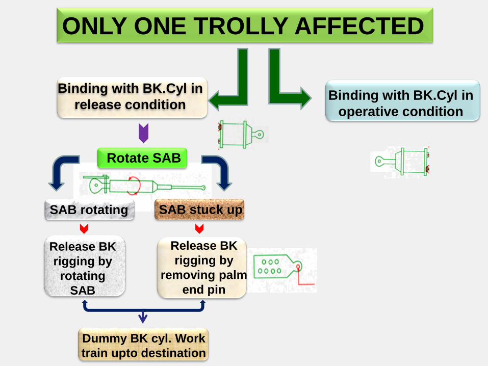
ONLY ONE TROLLY AFFECTED
Binding with BK.Cyl in
release condition Binding with BK.Cyl in
operative condition
Rotate SAB
SAB rotating SAB stuck up
Release BK
rigging by
rotating
SAB
Release BK
rigging by
removing palm
end pin
Dummy BK cyl. Work
train upto destination

Binding with BK.Cyl in operative condition
Operate QRV of DV
If BK cyl. released
Isolate BK cyl.
isolating cock
Isolate FP & AR isolating cock,
Isolate the DV and pull QRV
If piston
releases
If BK cyl. Does not release
Leave DV in isolate
condition
If piston does not
release
Isolate BK cyl. And pull
drain plug of BK cyl
QRV
ROTATE TO
ISOLATE DV

BOTH TROLEYS AFFECTED
Operate QRV of DV
If piston released
Isolate BK
cyl. & DV
Isolate FP & AR isolating
cock, isolate DV & Pull
QRV again
If piston does not
release
If piston
released
Leave DV in
isolating
condition
If piston does not
release
Open AR drain
cock & if piston
does not release
Isolate both cyl.&
open drain plug
of BK cyl.
ROTATE TO
ISOLATE DV
QRV

BMBS TROLLEYS AFFECTED

BRAKE PIPE
PRESSURE GAUGE
FEED PIPE
PRESSURE GAUGE FP
ANGLE COCK
ALARAM PULL CHAIN
SCHEMATIC DIAGRAM OF
BMBS AIR BRAKE SYSTEM
GD’S
EVB
BP
ANGLE COCK
AR
ISOLATING
COCK
AR
BP
ISOLATING COCK
BRAKE PIPE
FEED PIPE
PEAV
ISOLATING COCK
PEAV
CR DV
QRV
ISOLATING HANDLE
BC ISOLATING COCK
BC BC
DRAIN COCK

STEPS TO RELEASE
BRAKE BINDING
STEP-1
STEP-2
Close isolating cock of
BP & FP branch pipe line
Isolate DV by moving the
handle from vertical to
horizontal position & secure
BP
FP

STEP-3 Release DV by pulling QRV
till all the air escaped
Through DV
STEP-4 Close both bogie brake
Isolating cocks

STEP-5
Pull out the clutch &
rotate spindle rod
clock wise to
release the piston

FOR SLR
COACHES
Check hand brake and
ensure gap between
wheel and brake block.
Reset the PEAV & if not
success isolate the
PEAV isolating cock
IF ACP ON
COACHES

AIR BARKE SYSTEM ON LHB COACHES
(Axle Mounted Disc Brake)

Axle mounted
brake disc
Brake
calipers
Brake Pads

Brake
Cylinder

AIR BRAKE SYSTEM ON LHB COACHES
Principle characteristics of brake system:
Application time: 3-5 SEC
Release time: 15-20 SEC
BRAKE INDICATORS
BRAKE APPLIED BRAKE RELEASED
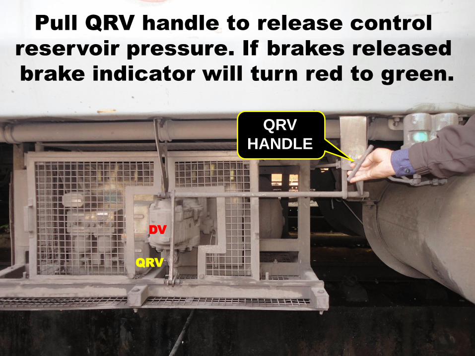
QRV
HANDLE
QRV
DV
Pull QRV handle to release control
reservoir pressure. If brakes released
brake indicator will turn red to green.

SAB WABCO BRAKE CONTROL PANEL
FEED PIPE
ISOLATING
COCK
CDTS
ISOLATING
COCK
BOGIE-1
ISOLATING
COCK
BOGIE-2
ISOLATING
COCK
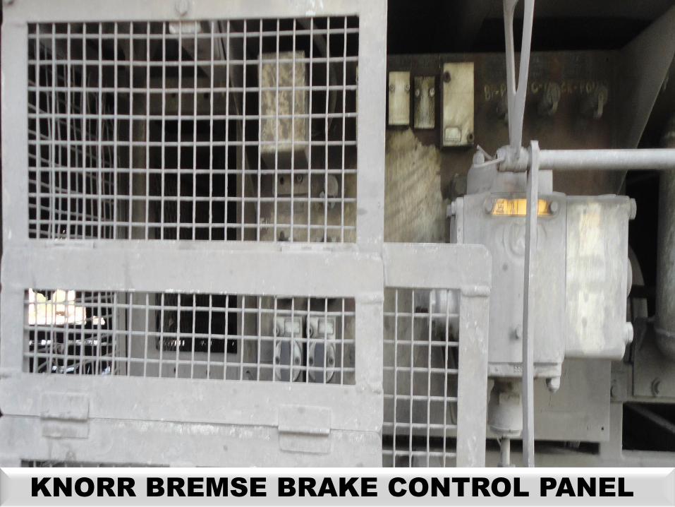
KNORR BREMSE BRAKE CONTROL PANEL

KNORR BREMSE BRAKE CONTROL PANEL
FEED PIPE
ISOLATING
COCK
CDTS
ISOLATING
COCK
BOGIE-1
ISOLATING
COCK
BOGIE-2
ISOLATING
COCK

SAB WABCO BRAKE CONTROL PANEL
FEED PIPE
ISOLATING
COCK
Turn the FP cock horizontal to
vertical to Isolate feed pipe supply
to aux. reservoir.

75 lt. AR
For CDTS 125 lt. AR for
brake system
AR
Drain cock
Open the drain cock of Aux. reservoir to
discharge the full pressure then close it.
The brake indicator will turn to green if
brake binding is due to pneumatic failure.

SAB WABCO BRAKE CONTROL PANEL
BOGIE-1
ISOLATING
COCK
BOGIE-2
ISOLATING
COCK
Isolate bogies by isolating both bogie cut out
cock, put FP in service and work the train.
The affected coach will run as piped vehicle.
FEED PIPE
ISOLATING
COCK

RESETING OF ACP

ACP RESETING PROCEDURE

SALIENT FEATURES &
WORKING PRINCIPLE OF
BMBS WAGON

GENERAL DESCRIPTION OF BMBS
The equipment consists of a transversely mounted
pneumatic actuator (Brake Cylinder) with a self-
contained, double acting slack adjuster, two brake
beams, two bell crank levers and interconnecting push
rods. The hand brake arrangement is available as a
mechanical model with two flexible hand brake cables.
The pneumatic actuator is 10” in diameter for application
on high friction brake shoe (K type) on casnub type
bogies. The system consists of a unique design with two
pneumatic actuators to deliver reliable braking
performance and is light in weight. It fits into any
standard IR casnub bogie and uses 58mm thick brake
shoes.

SALIENT FEATURES :-
1- Use of Two no’s of 10” Dia brake cylinders with automatic
load sensing device.
2- Use of 58 mm thick K type non asbestos composite
brake block.
3- Piston stroke of 56(+6,-0) mm in empty condition and 62
(+6,-0) mm in loaded condition is required to maintain.
4- Application of loads is at the ends the brake beam
instead of centre resulted no chances of bending of brake
beams.
5- Cylinder is with double acting slack adjustment feature
with constant piston stroke resulting is uniform brake
performances even as the brake shoes and wheels wears.

6- Total slack adjusting capacity is 500 mm including
brake block wear, wheel wear and all clearances.
7- All cylinders are equipped with an automatic piston
stroke indicator.
8- Replacement of the brake head is quickly and easy
by removal by only one pin.
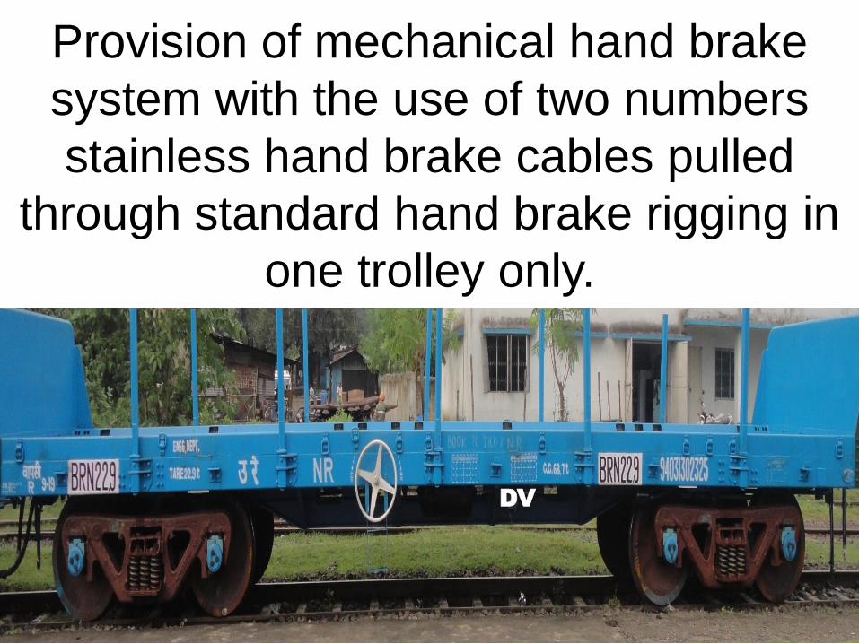
9- Provision of mechanical hand brake system with the
use of two no’s stainless hand brake cables pulled
through standard hand brake rigging.
10- Easy fitment of bogie mounted cylinder on any
standard bogies without making any modifications.

ADVANTAGES OF BMBS OVER CONVENTIONAL
BRAKE SYSTEM
1-SAB is eliminated providing in built slack adjuster to
take up slack automatically.
2- Brake Rigging completely eliminated.
3- Wt of BK system Reduced approx: 300 Kg resulting
more carrying capacity.
4- E/L system Modified to Automatic Load sensing hence
there is no L/E handle.
5- Mechanical efficiency ( Brake percentage) Increased
to 47.6% ( was 43.8% in case of BOXN)
6- Push Rod of conventional type eliminated BK rigging
eliminated so there was a low chance of hanging
parts in Train.
7- Braking Distance decreased.
8- Wheel wear is Reduced due to use of K-Type 58 mm
thick composite BK Block.
9- Speed of Train Increased due to better control.
10- Reliability of BK system is increased.
11- Low Maintenance Cost.
12- No need of Detachment of wagons in en route when
BK pipe Damage.
13- Cylinder is mounted parallel to the brake beam and
transfer forces through the bell cranks.

14- Improves the efficiency and alignments of the
braking forces with the wheels which reduced the
wear of shoes and wheels.
15- Use of pressure regulated load sensing device,
installed between body and bogie under frame act on
15 psi to maintain normal sensor arm travel of 95 mm.
16- Use of single stage distributor valve (conventional
type).
17- Use of Two bell crank levers and two Inter
connecting Push rods, to transmit braking force from
bk cyl. to wheel through primary and secondary brake
beams.

Brake cylinder with double acting
slack adjustment feature.


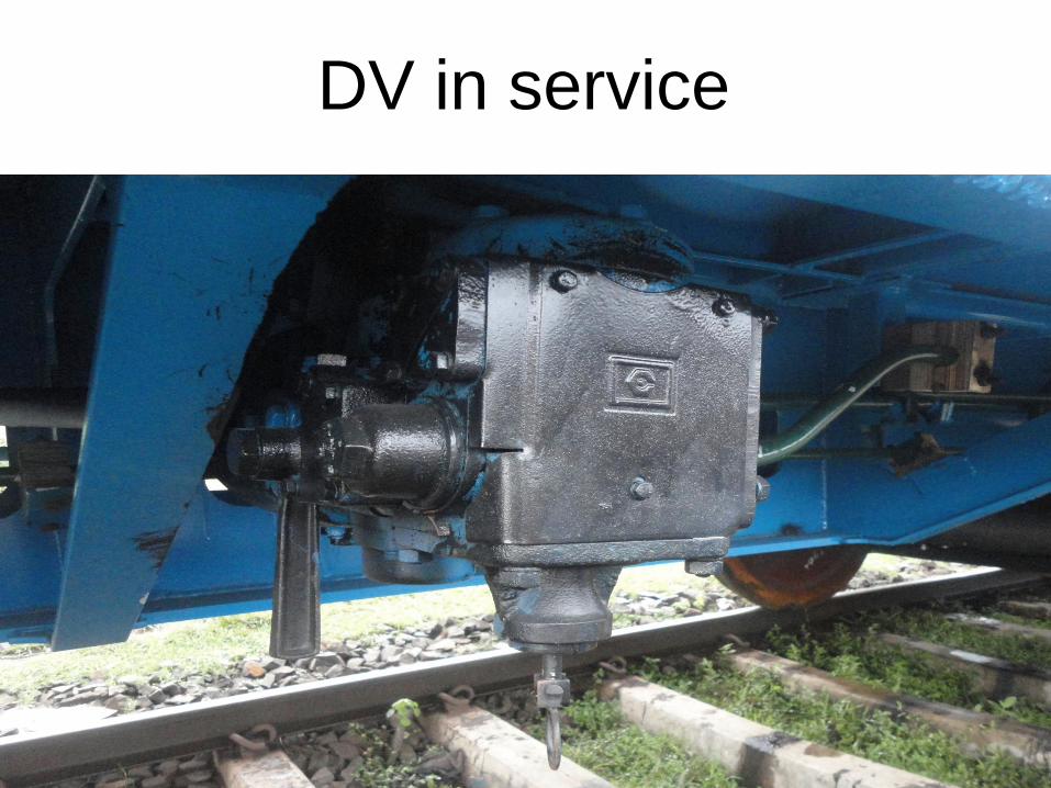
DV in service

Piston stroke
indicator
When BP reduced, piston moves outward
and the indicator comes out from the BC.

DV in isolated condition and manually
Released…

Piston moves inside
and the indicator also moves inside.
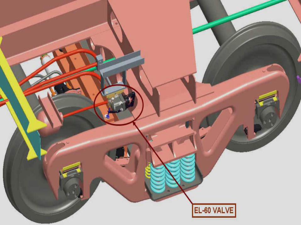

APM (EL-60 Valve)
Automatically changes the BC pressure, 3.8kg/cm2 /
2.2kg/cm2 depending upon loaded / empty
condition. Installed between Distributor Valve and
Brake Cylinder. Physical contact of lever with side
frame only during braking.
Mounted on under frame, takes Deflection
of Bolster taken against side frame.

Individual bogie can be isolated by isolating the
corresponding bogie COC.
Normal position
of bogie COC

Individual bogie can be isolated by isolating the
corresponding bogie COC.
Isolated position
of bogie COC

During single pipe operation the FP can be
isolated by FP COC.
Isolated position
of FP COC
DV
Provision of mechanical hand brake
system with the use of two numbers
stainless hand brake cables pulled
through standard hand brake rigging in
one trolley only.

Mechanical arrangement for
Hand brake.


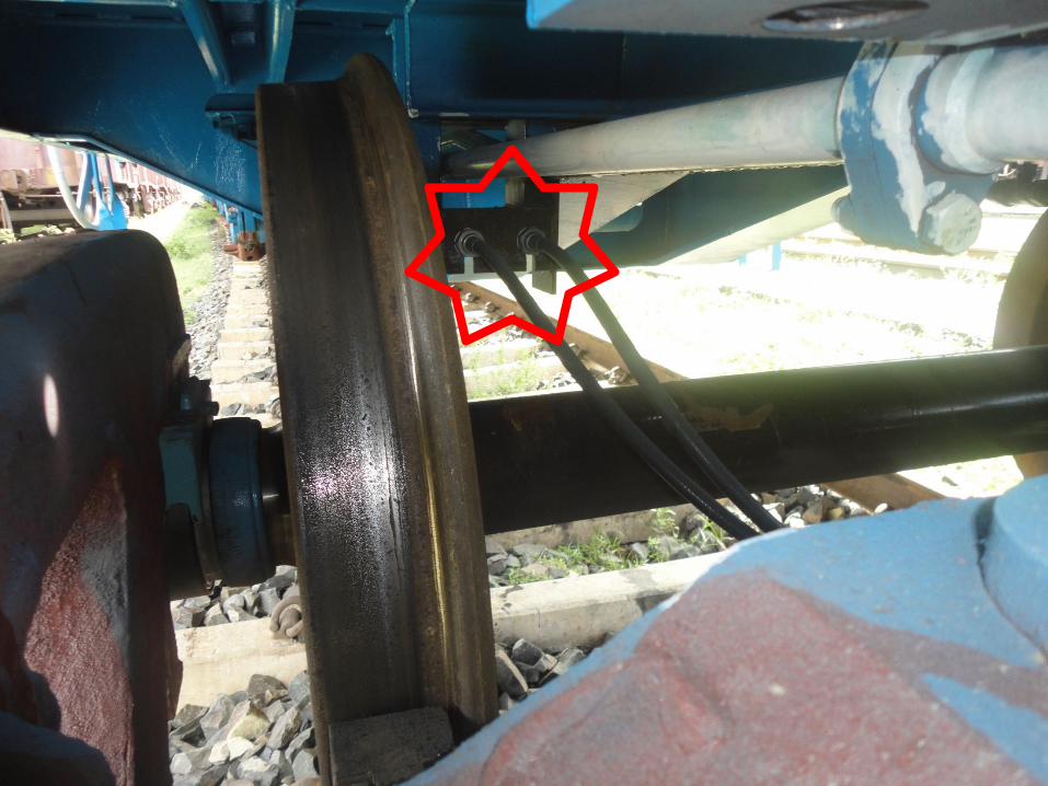


DV
To apply hand brake rotate the wheel
towards DV. (on either side)


As an indication the piston stroke
indicator will comes out.

DV
To release hand brake rotate the wheel
opposite to DV. (on either side)


As an indication the piston stroke
indicator will go inside.

To ensure the hand brake application
check the brake blocks are griping on
the wheel of corresponding trolley .


