3. Configure the management interface on each device using configuration groups.
set groups node0 system host-name <node0 hostname>set groups node0 interfaces fxp0 unit 0 family inet address <node0 mgmt IP>/<netmask>set groups node1 system host-name <node1 hostname>set groups node1 interfaces fxp0 unit 0 family inet address <node1 mgmt IP>/<netmask>
4. (Optional) Configure device-specific options.
set groups node0 snmp description <node0 snmp sysDesc>set groups node1 snmp description <node1 snmp sysDesc>
5. Apply the group configuration.
set apply-groups “${node}”
6. (Optional) Define the redundancy groups and RETH interfaces if using redundant Ethernet interfaces.
APPLICATION NOTE - Branch SRX Series and J Series Chassis Clustering
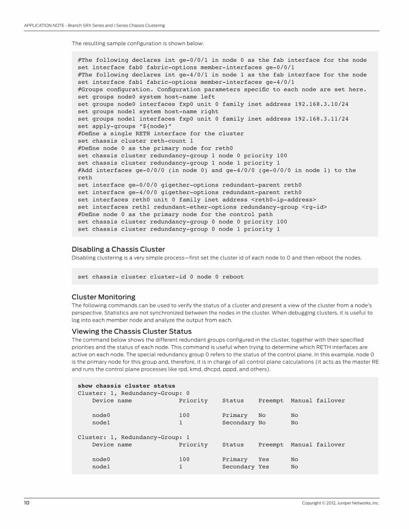
The resulting sample configuration is shown below:
#The following declares int ge-0/0/1 in node 0 as the fab interface for the nodeset interface fab0 fabric-options member-interfaces ge-0/0/1#The following declares int ge-4/0/1 in node 1 as the fab interface for the nodeset interface fab1 fabric-options member-interfaces ge-4/0/1#Groups configuration. Configuration parameters specific to each node are set here.set groups node0 system host-name leftset groups node0 interfaces fxp0 unit 0 family inet address 192.168.3.10/24set groups node1 system host-name rightset groups node1 interfaces fxp0 unit 0 family inet address 192.168.3.11/24set apply-groups “${node}”#Define a single RETH interface for the clusterset chassis cluster reth-count 1#Define node 0 as the primary node for reth0set chassis cluster redundancy-group 1 node 0 priority 100set chassis cluster redundancy-group 1 node 1 priority 1#Add interfaces ge-0/0/0 (in node 0) and ge-4/0/0 (ge-0/0/0 in node 1) to the rethset interface ge-0/0/0 gigether-options redundant-parent reth0set interface ge-4/0/0 gigether-options redundant-parent reth0set interfaces reth0 unit 0 family inet address <reth0-ip-address>set interfaces reth1 redundant-ether-options redundancy-group <rg-id>#Define node 0 as the primary node for the control pathset chassis cluster redundancy-group 0 node 0 priority 100set chassis cluster redundancy-group 0 node 1 priority 1
Disabling a Chassis Cluster Disabling clustering is a very simple process—first set the cluster id of each node to 0 and then reboot the nodes.
set chassis cluster cluster-id 0 node 0 reboot
Cluster MonitoringThe following commands can be used to verify the status of a cluster and present a view of the cluster from a node’s
perspective. Statistics are not synchronized between the nodes in the cluster. When debugging clusters, it is useful to
log into each member node and analyze the output from each.
Viewing the Chassis Cluster StatusThe command below shows the different redundant groups configured in the cluster, together with their specified
priorities and the status of each node. This command is useful when trying to determine which RETH interfaces are
active on each node. The special redundancy group 0 refers to the status of the control plane. In this example, node 0
is the primary node for this group and, therefore, it is in charge of all control plane calculations (it acts as the master RE
and runs the control plane processes like rpd, kmd, dhcpd, pppd, and others).
show chassis cluster statusCluster: 1, Redundancy-Group: 0 Device name Priority Status Preempt Manual failover
node0 100 Primary No No node1 1 Secondary No No
Cluster: 1, Redundancy-Group: 1 Device name Priority Status Preempt Manual failover
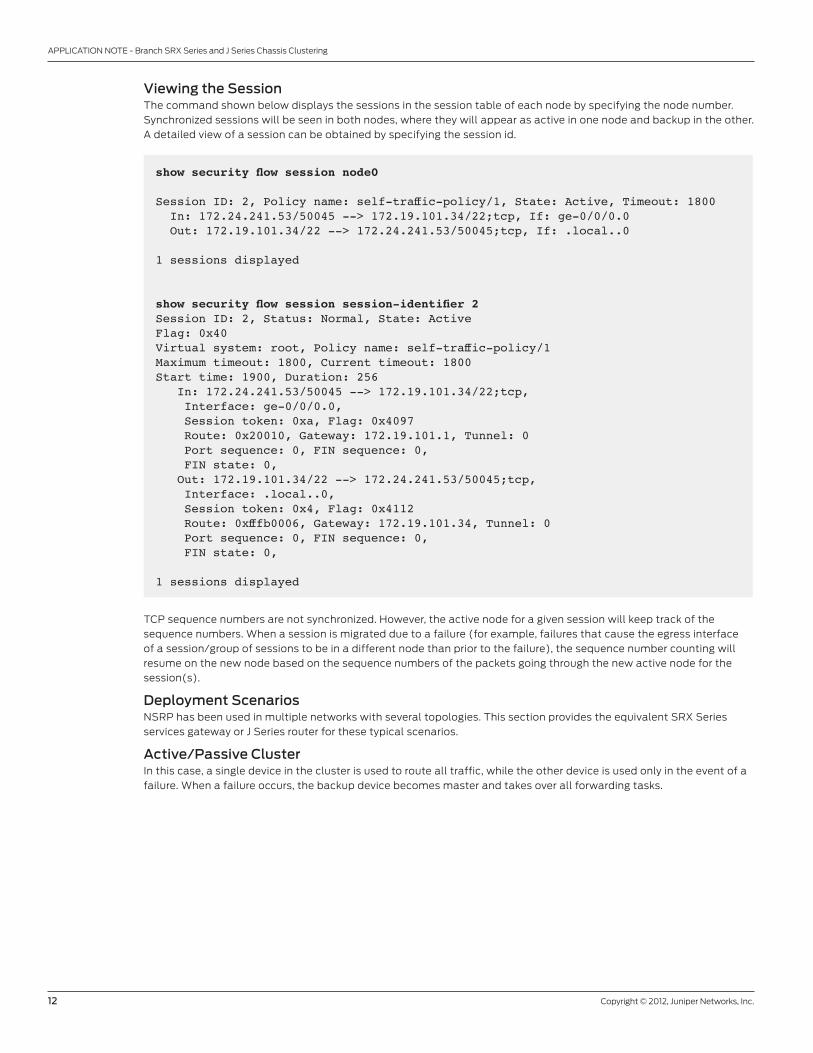
show security flow session session-identifier 2 Session ID: 2, Status: Normal, State: ActiveFlag: 0x40Virtual system: root, Policy name: self-traffic-policy/1Maximum timeout: 1800, Current timeout: 1800Start time: 1900, Duration: 256 In: 172.24.241.53/50045 --> 172.19.101.34/22;tcp, Interface: ge-0/0/0.0, Session token: 0xa, Flag: 0x4097 Route: 0x20010, Gateway: 172.19.101.1, Tunnel: 0 Port sequence: 0, FIN sequence: 0, FIN state: 0, Out: 172.19.101.34/22 --> 172.24.241.53/50045;tcp, Interface: .local..0, Session token: 0x4, Flag: 0x4112 Route: 0xfffb0006, Gateway: 172.19.101.34, Tunnel: 0 Port sequence: 0, FIN sequence: 0, FIN state: 0,
1 sessions displayed
TCP sequence numbers are not synchronized. However, the active node for a given session will keep track of the
sequence numbers. When a session is migrated due to a failure (for example, failures that cause the egress interface
of a session/group of sessions to be in a different node than prior to the failure), the sequence number counting will
resume on the new node based on the sequence numbers of the packets going through the new active node for the
session(s).
Deployment ScenariosNSRP has been used in multiple networks with several topologies. This section provides the equivalent SRX Series
services gateway or J Series router for these typical scenarios.
Active/Passive Cluster In this case, a single device in the cluster is used to route all traffic, while the other device is used only in the event of a
failure. When a failure occurs, the backup device becomes master and takes over all forwarding tasks.
APPLICATION NOTE - Branch SRX Series and J Series Chassis Clustering
Figure 3: Active/passive cluster
Active/passive can be achieved using RETH interfaces, just as one would do using VSIs. The redundancy group
determines the RETH state by monitoring the state of the physical interfaces in reth0 and reth1. If any of these
interfaces fails, the group is declared inactive by the system that hosts the failing interface. On a failure, both RETH
interfaces will fail over simultaneously, as they belong to the same redundancy group. This configuration minimizes the
traffic around the fabric link, as only one node in the cluster will be forwarding traffic at any given time.
#Groups Definitionsset groups node0 system host-name J2320-Aset groups node0 interfaces fxp0 unit 0 family inet address 192.168.3.110/24set groups node1 system host-name J2320-Bset groups node1 interfaces fxp0 unit 0 family inet address 192.168.3.111/24set apply-groups “${node}”
#Cluster Configuration, redundancy-group 0 determines the status of the RE mastership, while redundancy-group 1 is used to control the reth interfacesset chassis cluster reth-count 2set chassis cluster heartbeat-threshold 3set chassis cluster node 0set chassis cluster node 1set chassis cluster redundancy-group 0 node 0 priority 100set chassis cluster redundancy-group 0 node 1 priority 1
#The ge-0/0/0 interface on each node is used as the fabric interface between the nodesset interfaces fab0 fabric-options member-interfaces ge-0/0/1set interfaces fab1 fabric-options member-interfaces ge-4/0/1
APPLICATION NOTE - Branch SRX Series and J Series Chassis Clustering
#Note how the redundancy-group 1 is configured to monitor all the physical interfaces forwarding traffic. The preempt keyword causes the mastership to be reverted back to the primary node for the group (node 0, which has a higher priority) when the failing interface causing the switchover comes back upset chassis cluster redundancy-group 1 node 0 priority 100set chassis cluster redundancy-group 1 node 1 priority 1set chassis cluster redundancy-group 1 preemptset chassis cluster redundancy-group 1 interface-monitor fe-1/0/0 weight 255set chassis cluster redundancy-group 1 interface-monitor fe-5/0/0 weight 255set chassis cluster redundancy-group 1 interface-monitor ge-0/0/0 weight 255set chassis cluster redundancy-group 1 interface-monitor ge-4/0/0 weight 255
#(Optionally) If both data processing and control plane functions want to be performed in the same node, then redundancy-group 0 must monitor also the physical interfaces. If control and data planes are allowed to fail over independently, the following four commands should not be set.set chassis cluster redundancy-group 0 interface-monitor fe-1/0/0 weight 255set chassis cluster redundancy-group 0 interface-monitor fe-5/0/0 weight 255set chassis cluster redundancy-group 0 interface-monitor ge-0/0/0 weight 255set chassis cluster redundancy-group 0 interface-monitor ge-4/0/0 weight 255
#Just as regular interfaces, reth interfaces must be part of a security zoneset security zones security-zone Untrust interfaces reth1.0set security zones security-zone Trust interfaces reth0.0
Asymmetric Routing ScenarioThis scenario makes use of the asymmetric routing capability of Junos OS with enhanced services. Traffic received by
a node is matched against that node’s session table. The result of this lookup indicates whether that node processes
the session or forwards it to the other node through the fabric link. Sessions can then be anchored to any device in
the cluster; and, as long as the session tables are replicated, the traffic will be correctly processed. To minimize fabric
traffic, sessions are always anchored to the node hosting the egress interface for that particular connection.
APPLICATION NOTE - Branch SRX Series and J Series Chassis Clustering
Figure 4: Asymmetric routing scenario
Figure 4 shows an example of how asymmetric routing is supported. In this scenario two Internet connections are used
with one being preferred. The connection to the trust zone is made using a RETH interface to provide LAN redundancy
for the devices in the trust zone. For illustrative purposes, we will describe two failover cases in which sessions originate
in the trust zone with a destination of the Internet (untrust zone).
Case I: Failures in the Trust Zone RETHUnder normal operating conditions, traffic will flow from the trust zone to the interface ge-0/0/0 (belonging to
reth0.0) in node 0. Since the primary Internet connection resides in node 0, the sessions will be created in both node 0
and node 1 but will only be active in node 0 (since the egress interface for all of these sessions is fe-1/0/0 belonging to
node 0).
A failure in the ge-0/0/0 interface will trigger a failover of the redundancy group, causing the interface ge-4/0/0 (ge-
0/0/0 in node 1) to become active. After the failover, traffic will arrive at node 1. After session lookup, the traffic will be
sent to node 0 as the session will be active in this node (since the egress interface, fe-1/0/0 is hosted in this node 0).
Node 0 will then process the traffic and forward it to the Internet. The return traffic will follow a similar process. Traffic
will arrive at node 0, be processed at node 0 (since the session is anchored to this node), and be sent to node 1 through
the fabric interface where node 1 will forward it through the ge-4/0/0 interface.
Case II: Failures in the Untrust Zone InterfacesThis case differs from the previous one in that sessions will be migrated from node to node. As in the previous case,
traffic will be processed only by node 0 under normal operating conditions. A failure of interface fe-1/0/0 connected
to the Internet will cause a change in the routing table, which will have a default route after the failure pointing to
interface fe-5/0/0 in node 1. After the failure, the sessions in node 0 will become inactive (since the egress interface
now will reside in node 1), and the backup sessions in node 1 will become active. Traffic arriving from the trust zone will
still be received on interface ge-0/0/0, but will be forwarded to node 1 for processing. After traffic is processed in node
1, it will be forwarded to the Internet through the fe-5/0/0 interface.
APPLICATION NOTE - Branch SRX Series and J Series Chassis Clustering
Note that if this scenario were used with source NAT, to accommodate different address spaces assigned by different
providers, the above would not work as the egress sessions would be NATed differently after the failover (this is not
a limitation of the HA implementation, but a consequence of the fact that if two Internet service providers (ISPs)
are used, the customer doesn’t own a public address space, and a failure in one of the ISPs will result in the loss of
connectivity from all IPs belonging to the failed service provider).
#Cluster Configuration, redundancy-group 1 is used to control the RETH interface connected to the trust zone. Note how the redundancy group (and therefore reth0) will only failover if either fe-1/0/0 or fe-5/0/0 fail, but not if any of the interfaces connected to the Internet fails.set chassis cluster reth-count 1set chassis cluster node 0set chassis cluster node 1set chassis cluster redundancy-group 1 node 0 priority 100set chassis cluster redundancy-group 1 node 1 priority 1set chassis cluster redundancy-group 1 preemptset chassis cluster redundancy-group 1 interface-monitor fe-1/0/0 weight 255set chassis cluster redundancy-group 1 interface-monitor fe-5/0/0 weight 255
#Interface Definitionsset interfaces ge-0/0/0 unit 0 family inet address 1.4.0.202/24set interfaces fe-1/0/0 fastether-options redundant-parent reth0set interfaces fe-1/0/1 disableset interfaces ge-4/0/0 unit 0 family inet address 1.2.1.233/24set interfaces fe-5/0/0 fastether-options redundant-parent reth0set interfaces reth0 unit 0 family inet address 10.16.8.1/24
#ge-0/0/1 one each node will be used for the fab interfacesset interfaces fab0 fabric-options member-interfaces ge-0/0/1set interfaces fab1 fabric-options member-interfaces ge-4/0/1
#We have two static routes, one to each ISP, but the preferred one is through ge-0/0/0set routing-options static route 0.0.0.0/0 qualified-next-hop 1.4.0.1 metric 10set routing-options static route 0.0.0.0/0 qualified-next-hop 1.2.1.1 metric 100#Zones Definitionsset security zones security-zone Untrust interfaces ge-0/0/0.0 host-inbound-traffic system-services dhcpset security zones security-zone Untrust interfaces ge-4/0/0.0 host-inbound-traffic system-services dhcpset security zones security-zone Trust interfaces reth0.0
#Finally a permit all security policy from Trust to Untrust zoneset security policies from-zone Trust to-zone Untrust policy ANY match source-address anyset security policies from-zone Trust to-zone Untrust policy ANY match destination-address anyset security policies from-zone Trust to-zone Untrust policy ANY match application anyset security policies from-zone Trust to-zone Untrust policy ANY then permit
APPLICATION NOTE - Branch SRX Series and J Series Chassis Clustering
Description and Deployment ScenarioConnecting to a Cluster Using SSH/TelnetAccessing the primary node of a cluster is as easy as establishing a connection to any of the node’s interfaces (other
than the fxp0, that is). Either L3 or Redundant Ethernet (RETH) interfaces will always direct the traffic to the primary
node, whichever node that is. Both deployment scenarios are common and are depicted in the following diagrams:
Figure 7: Common branch deployment scenarios for SRX Series clustering
In both cases, establishing a connection to any of the local addresses will connect to the primary node (to be precise, it
will connect to the primary node of redundancy group 0). For example, we can connect to the primary node even when
the RETH interface, member of the redundancy group 1, is active in a different node (the same applies to L3 interfaces,
even if they physically reside in the backup node).
$ssh [email protected]’s password: --- JUNOS 10.2R1.3 built 2010-05-14 15:13:40 UTC{primary:node1}labuser@BranchGW> show chassis cluster status Cluster ID: 3 Node Priority Status Preempt Manual failover
Redundancy group: 0 , Failover count: 3 node0 200 secondary no yes node1 255 primary no yes
Redundancy group: 1 , Failover count: 4 node0 254 primary yes no node1 1 secondary yes no
Login into the secondary node from the primaryMost monitoring commands will show the status of both nodes. When needed, it is still possible to connect to the
secondary node from the primary, as shown below:
labuser@BranchGW> request routing-engine login node 0 --- JUNOS 10.2R1.3 built 2010-05-14 15:13:40 UTC
INTERNET
BRANCH OFFICE
EX SeriesSwitch
EX SeriesSwitch
EX SeriesSwitch
SRX SeriesCluster
SRX SeriesCluster
RETH0.0Redundant Ethernet interface connected to the trust networks
RETH1.0Redundant Ethernet interface connected
to the internet
INTERNET
BRANCH OFFICE
EX SeriesSwitch
EX SeriesSwitch
SRX SeriesCluster
SRX SeriesCluster
RETH0.0Redundant Ethernet interface connected to the trust networks
L3 Interfacesge-0/0/0.0 interface connected to the Internet
APPLICATION NOTE - Branch SRX Series and J Series Chassis Clustering
{secondary:node0}Exiting the session will bring us back to the primary node:{secondary:node0}labuser@BranchGW> exit rlogin: connection closed{primary:node1}labuser@BranchGW>
SSH management of a cluster is a good example of how all management protocols behave. It is simple to connect to
the primary node, and connecting to the secondary node must be done through the primary.
NSM management of a cluster is not any different. NSM versions prior to 2010.2 require NETCONF connections to both
nodes, which is why in-band management of a cluster in older versions is problematic. The solution to this problem is
the subject of the next section.
In-band Management Through Network and Security Manager NSM management of SRX Series gateways in cluster configurations was modeled after the management of ScreenOS
devices connected using the NetScreen Redundancy Protocol (NSRP), where NSM connects to each member forming
an HA pair independently. However, other Junos OS-based devices running in HA mode can be managed through NSM
using a single connection. In particular, NSM can manage Juniper Networks EX Series Ethernet Switches with Virtual
Chassis technology by connecting to the master node only. In this case, configuration and monitoring of the chassis is
done through this single connection.
NSM version 2010.2 has added the ability to manage a branch SRX Series cluster just like an EX Series with Virtual
Chassis, thus requiring only a single connection to the primary node. This change requires modifications both to
the devices so that they identify to NSM as a Virtual Chassis, and to NSM. For backwards compatibility purposes,
clusters identify to NSM as a chassis cluster by default, and it is expected that they will be managed through the fxp0
interfaces.
The default behavior can be changed in the device by adding the following configuration to the cluster:
labuser@BranchGW# set chassis cluster network-management cluster-master
Adding the device to NSM is similar to adding an EX Series Virtual Chassis. Simply mark the “virtual-chassis” check box
when adding the cluster. Note how the cluster must be added as a single node, and not as a chassis cluster.
Figure 8: Adding a cluster as a Virtual Chassis in NSM
APPLICATION NOTE - Branch SRX Series and J Series Chassis Clustering
The hardware inventory will display the chassis serial number of the primary node, and a failover will result in an
update reflecting the serial number change.
Most configuration and monitoring options are supported, with the following exceptions (which will be addressed in a
subsequent release):
• Chassis inventory displays “sub-component” instead of “FPC.”
• The “chassis serial number” as obtained from cached copy in NSM from “get-system-information” contains old
information and is not correct.
• Software update of both devices through NSM is not supported.
• The Virtual Chassis status view shows no valid information.
• License inventory shows information only about primary node.
• Hardware inventory gets out of sync when the primary node is rebooted.
• Reboot commands sent through NSM are only applied on the primary node.
• Only control plane logs from the primary node are sent to NSM.
• Data plane logs (like session logs, IDP attacks, etc) can be sent from both nodes directly to NSM in structured-syslog
format. Support for structured-syslog messages on NSM requires version 2010.4R2 or later.
When updating IDP signatures, NSM pushes the security package to the primary node, after which it sends a remote
procedure call (RPC) to the cluster to trigger an upgrade. Under normal circumstances, only the primary node will get
updated. To overcome this limitation, a Junos OS script has been developed that takes care of updating the secondary
node automatically, after the primary has been updated.
Updating the IDP SignaturesWhen a chassis cluster is managed through an in-band connection, only the control plane of the primary node will have
connectivity to other devices. In particular, only the primary node is able to download new security packages from the
update servers.
The “request security idp security-package download node primary” and the “request security idp security-package
install node primary” commands can still be used to download and install the security package in the primary node
(using these commands without specifying the node will still work on the primary, but fail on the secondary node).
A cluster can automatically copy and install a new installed security package in the secondary, by loading and enabling
the “idp-update.xslt” event script. The script (which can be downloaded from the following location: https://matrix.juniper.net/community/products/security/srxseries/blog/2010/06/01/updating-the-idp-security-package-in-a-cluster-with-no-fxp0-access-to-the-internet) must be copied to the “/var/db/scripts/event” directory in both nodes,
after which it must be enabled using the following configuration:
set event-options policy idp-update events IDP_SECURITY_INSTALL_RESULTset event-options policy idp-update attributes-match idp_security_install_result.status matches successfulset event-options policy idp-update then event-script idp-update.xslt
With the script enabled, all IDP signature update methods are supported, including NSM, command-line interface
(CLI), and auto-update.
It is possible to manually synchronize the signature packages between the nodes by manually copying the contents
of the /var/db/idpd/sec-download directory in the primary node to the secondary. Files can be copied between
nodes by using the “file copy” command and specifying the backup node as the target (file copy /var/db/idpd/sec-
download/<filename> nodeX:/var/db/idpd/sec-download) where nodeX is either node0 or node1, depending on which
node is the backup.
Similarly, the IDP policy templates can be synchronized by simply copying the templates stored in the /var/db/scripts/
commit directory to the secondary node.
Using SNMPJust like in the SSH/Telnet case, the primary device can answer SNMP queries and generate SNMP traps for both
nodes. At the time of this writing, not all MIBs supported by branch SRX Series devices work across a cluster, but most
APPLICATION NOTE - Branch SRX Series and J Series Chassis Clustering
Software UpgradesJunos OS can be upgraded by connecting to each node individually and executing the “request system software add”
command. The image can be copied to the primary node using FTP or SCP (provided that FTP or SSH are enabled).
Once the image is copied to the primary node, the “file copy” command can be used to copy the file into the secondary
node. The following procedure details how to upgrade both nodes of a cluster managed in-band (the examples were
done in a J Series cluster, but the procedure and commands are the same in both branch SRX Series and J Series
clusters):
1. Copy the software image into the primary node using your preferred method (in this example, the file is stored in /
var/tmp).
2. Copy the files from primary to backup node using the file copy command (it might take a few minutes; in this
example the image was copied to the /var/tmp directory in node0).
labuser@J2320-1# run file copy /var/tmp/junos-jsr-10.2R1.3-domestic.tgz node1:/var/tmp
3. Login to the backup node and load the new image.
labuser@J2320-1# run request routing-engine login node 1 --- JUNOS 10.1-20100515.0 built 2010-05-15 06:07:46 UTC{secondary:node1}labuser@J2320-2> request system software add /var/tmp/junos-jsr-10.2R1.3-domestic.tgz no-copy unlink NOTICE: Validating configuration against junos-jsr-10.2R1.3-domestic.tgz.NOTICE: Use the ‘no-validate’ option to skip this if desired.Checking compatibility with configurationInitializing...Verified manifest signed by PackageProduction_10_1_0Verified junos-10.1-20100515.0-domestic signed by PackageProduction_10_1_0Using /var/tmp/junos-jsr-10.2R1.3-domestic.tgzChecking junos requirements on /Saving boot file package in /var/sw/pkg/junos-boot-jsr-10.2R1.3.tgzVerified manifest signed by PackageProduction_10_2_0Hardware Database regeneration succeededValidating against /config/juniper.conf.gzcp: /cf/var/validate/chroot/var/etc/resolv.conf and /etc/resolv.conf are identical (not copied).cp: /cf/var/validate/chroot/var/etc/hosts and /etc/hosts are identical (not copied).Network security daemon: warning: You have enabled/disabled inet6 flow.Network security daemon: You must reboot the system for your change to take effect.Network security daemon: If you have deployed a cluster, be sure to reboot all nodes.mgd: commit completeValidation succeededValidating against /config/rescue.conf.gzNetwork security daemon: warning: You have enabled/disabled inet6 flow.Network security daemon: You must reboot the system for your change to take effect.Network security daemon: If you have deployed a cluster, be sure to reboot all nodes.
APPLICATION NOTE - Branch SRX Series and J Series Chassis Clustering
mgd: commit completeValidation succeededInstalling package ‘/var/tmp/junos-jsr-10.2R1.3-domestic.tgz’ ...Verified junos-boot-jsr-10.2R1.3.tgz signed by PackageProduction_10_2_0Verified junos-jsr-10.2R1.3-domestic signed by PackageProduction_10_2_0Available space: 333778 require: 4160Saving boot file package in /var/sw/pkg/junos-boot-jsr-10.2R1.3.tgzJUNOS 10.2R1.3 will become active at next rebootWARNING: A reboot is required to load this software correctlyWARNING: Use the ‘request system reboot’ commandWARNING: when software installation is completeSaving state for rollback ...Removing /var/tmp/junos-jsr-10.2R1.3-domestic.tgz{secondary:node1}labuser@J2320-2> exit
4. Upgrade the primary node.
labuser@J2320-1# run request system software add /var/tmp/junos-jsr-10.2R1.3-domestic.tgz no-copy unlink NOTICE: Validating configuration against junos-jsr-10.2R1.3-domestic.tgz.NOTICE: Use the ‘no-validate’ option to skip this if desired.Checking compatibility with configurationInitializing...Verified manifest signed by PackageProduction_10_1_0Verified junos-10.1-20100515.0-domestic signed by PackageProduction_10_1_0Using /var/tmp/junos-jsr-10.2R1.3-domestic.tgzChecking junos requirements on /Saving boot file package in /var/sw/pkg/junos-boot-jsr-10.2R1.3.tgzVerified manifest signed by PackageProduction_10_2_0Hardware Database regeneration succeededValidating against /config/juniper.conf.gzcp: /cf/var/validate/chroot/var/etc/resolv.conf and /etc/resolv.conf are identical (not copied).cp: /cf/var/validate/chroot/var/etc/hosts and /etc/hosts are identical (not copied).Network security daemon: warning: You have enabled/disabled inet6 flow.Network security daemon: You must reboot the system for your change to take effect.Network security daemon: If you have deployed a cluster, be sure to reboot all nodes.mgd: commit completeValidation succeededValidating against /config/rescue.conf.gzmgd: commit completeValidation succeededInstalling package ‘/var/tmp/junos-jsr-10.2R1.3-domestic.tgz’ ...
APPLICATION NOTE - Branch SRX Series and J Series Chassis Clustering
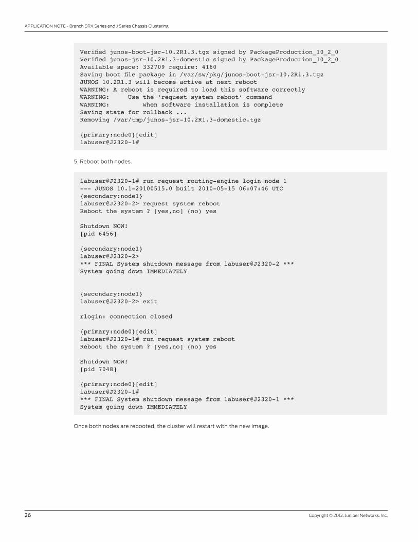
Verified junos-boot-jsr-10.2R1.3.tgz signed by PackageProduction_10_2_0Verified junos-jsr-10.2R1.3-domestic signed by PackageProduction_10_2_0Available space: 332709 require: 4160Saving boot file package in /var/sw/pkg/junos-boot-jsr-10.2R1.3.tgzJUNOS 10.2R1.3 will become active at next rebootWARNING: A reboot is required to load this software correctlyWARNING: Use the ‘request system reboot’ commandWARNING: when software installation is completeSaving state for rollback ...Removing /var/tmp/junos-jsr-10.2R1.3-domestic.tgz
{primary:node0}[edit]labuser@J2320-1#
5. Reboot both nodes.
labuser@J2320-1# run request routing-engine login node 1 --- JUNOS 10.1-20100515.0 built 2010-05-15 06:07:46 UTC{secondary:node1}labuser@J2320-2> request system reboot Reboot the system ? [yes,no] (no) yes
Shutdown NOW![pid 6456]
{secondary:node1}labuser@J2320-2> *** FINAL System shutdown message from labuser@J2320-2 *** System going down IMMEDIATELY {secondary:node1}labuser@J2320-2> exit
rlogin: connection closed
{primary:node0}[edit]labuser@J2320-1# run request system reboot Reboot the system ? [yes,no] (no) yes
Shutdown NOW![pid 7048]
{primary:node0}[edit]labuser@J2320-1# *** FINAL System shutdown message from labuser@J2320-1 *** System going down IMMEDIATELY
Once both nodes are rebooted, the cluster will restart with the new image.
APPLICATION NOTE - Branch SRX Series and J Series Chassis Clustering
3500132-003-EN Feb 2012
Copyright 2012 Juniper Networks, Inc. All rights reserved. Juniper Networks, the Juniper Networks logo, Junos, NetScreen, and ScreenOS are registered trademarks of Juniper Networks, Inc. in the United States and other countries. All other trademarks, service marks, registered marks, or registered service marks are the property of their respective owners. Juniper Networks assumes no responsibility for any inaccuracies in this document. Juniper Networks reserves the right to change, modify, transfer, or otherwise revise this publication without notice.
EMEA Headquarters
Juniper Networks Ireland
Airside Business Park
Swords, County Dublin, Ireland
Phone: 35.31.8903.600
EMEA Sales: 00800.4586.4737
Fax: 35.31.8903.601
APAC Headquarters
Juniper Networks (Hong Kong)
26/F, Cityplaza One
1111 King’s Road
Taikoo Shing, Hong Kong
Phone: 852.2332.3636
Fax: 852.2574.7803
Corporate and Sales Headquarters
Juniper Networks, Inc.
1194 North Mathilda Avenue
Sunnyvale, CA 94089 USA
Phone: 888.JUNIPER (888.586.4737)
or 408.745.2000
Fax: 408.745.2100
www.juniper.net
To purchase Juniper Networks solutions,
please contact your Juniper Networks
representative at 1-866-298-6428 or
authorized reseller.
Printed on recycled paper
SummaryThe branch SRX Series services gateways and J Series chassis cluster is a simple feature to implement that ensures
reliable enterprise connectivity between branch sites and corporate headquarters or regional offices. It provides stateful
traffic failover between two Juniper security devices while maintaining the abstraction of a single device, which simplifies
network design. The feature has been carefully designed to address many common connectivity challenges such as
asymmetric traffic, VPNs, and mixed LAN/WAN environments. Juniper Networks SRX Series for the branch and J Series
Services Routers employing chassis cluster provide a foundation for reliable and high-performance network deployments.
About Juniper NetworksJuniper Networks is in the business of network innovation. From devices to data centers, from consumers to cloud
providers, Juniper Networks delivers the software, silicon and systems that transform the experience and economics of
networking. The company serves customers and partners worldwide. Additional information can be found at