35
Brazed Heat Exchangers - Edition 2 Click Anywhere to enter
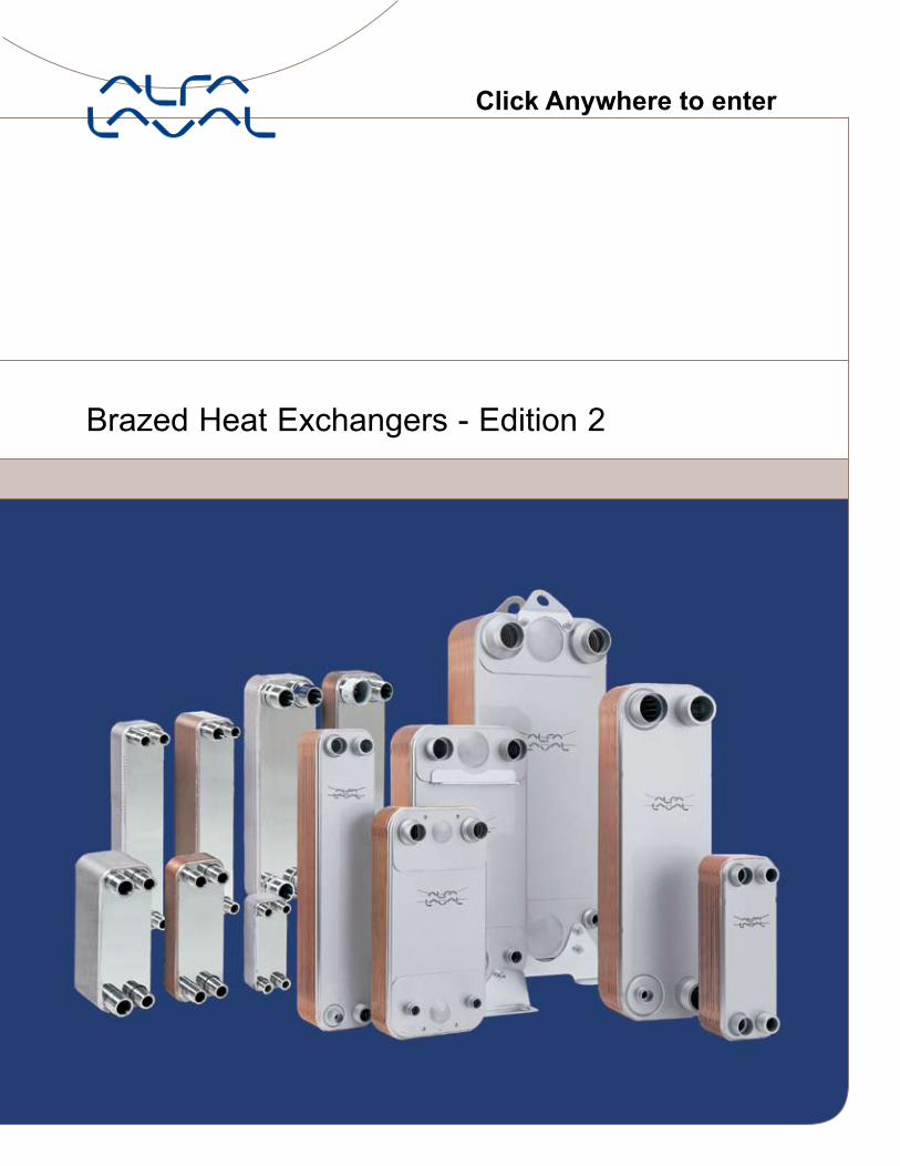
Brazed Heat Exchangers - Edition 2
Click Anywhere to enter
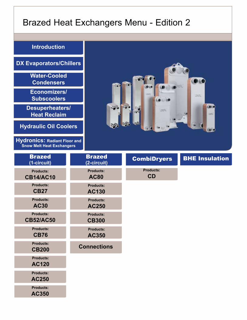
Brazed Heat Exchangers Menu - Edition 2
Introduction
DX Evaporators/Chillers
Water-Cooled Condensers
Economizers/ Subscoolers
Desuperheaters/ Heat Reclaim
Hydraulic Oil Coolers
Hydronics: Radiant Floor and Snow Melt Heat Exchangers
Products: AC350
Products: AC250
Products: CB200
Products: CB52/AC50
Products: CB76
Products: AC120
Products: CB27
Brazed(1-circuit)
Products: CB14/AC10
Products: AC30
Brazed(2-circuit)
CombiDryers BHE Insulation
Products: CB300Products: AC350
Products: AC130
Products: AC80
Products: AC250
Products: CD
Connections
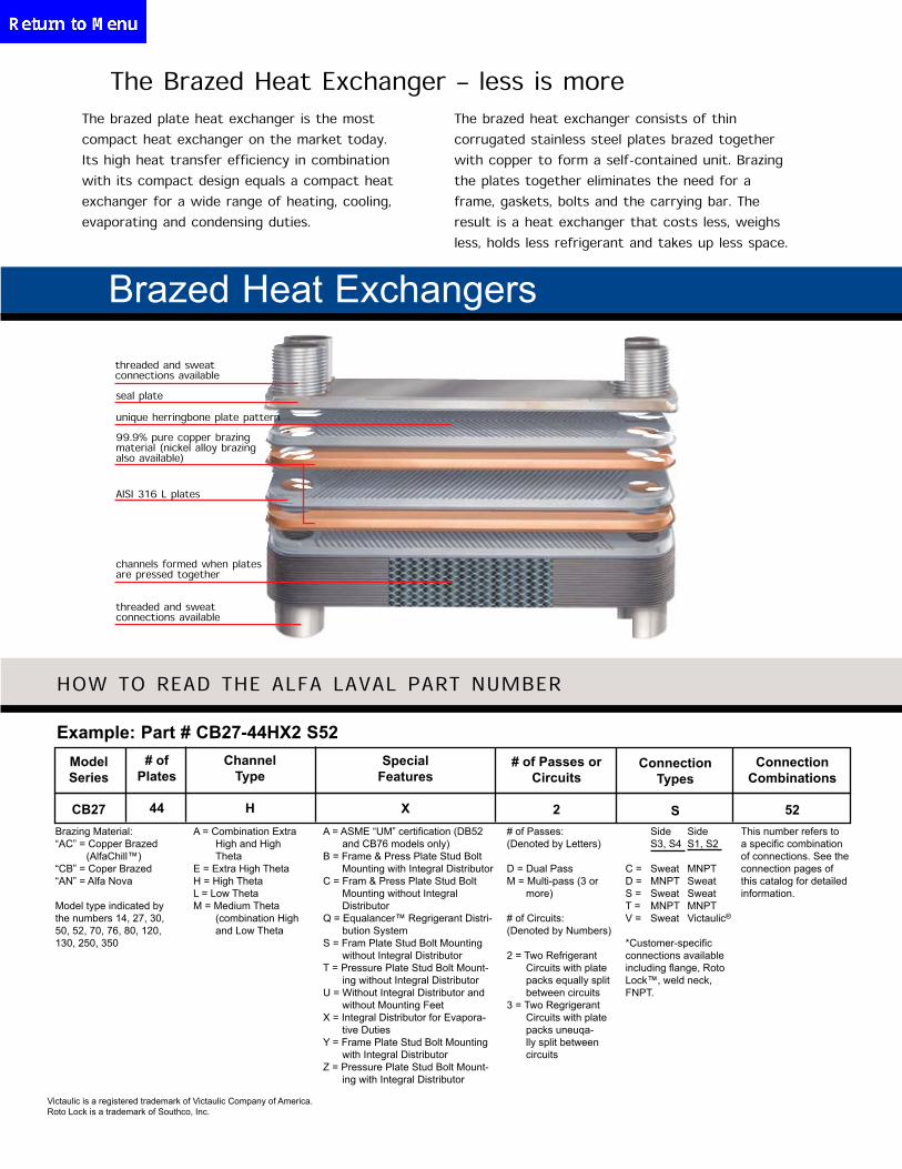
The Brazed Heat Exchanger – less is moreThe brazed plate heat exchanger is the most
compact heat exchanger on the market today.
Its high heat transfer efficiency in combination
with its compact design equals a compact heat
exchanger for a wide range of heating, cooling,
evaporating and condensing duties.
The brazed heat exchanger consists of thin
corrugated stainless steel plates brazed together
with copper to form a self-contained unit. Brazing
the plates together eliminates the need for a
frame, gaskets, bolts and the carrying bar. The
result is a heat exchanger that costs less, weighs
less, holds less refrigerant and takes up less space.
Brazed Heat Exchangers
threaded and sweat connections available
seal plate
AISI 316 L plates
unique herringbone plate pattern
99.9% pure copper brazing material (nickel alloy brazing also available)
channels formed when plates are pressed together
threaded and sweat connections available
HOW TO READ THE ALFA LAVAL PART NUMBER
Example: Part # CB27-44HX2 S52ModelSeries
CB27
# of Plates
44
Channel Type
H
Special Features
X
# of Passes or Circuits
2
Connection Types
S
Connection Combinations
52Brazing Material:“AC” = Copper Brazed
(AlfaChill™)“CB” = Coper Brazed“AN” = Alfa Nova
Model type indicated by the numbers 14, 27, 30, 50, 52, 70, 76, 80, 120, 130, 250, 350
A = Combination Extra High and High Theta
E = Extra High ThetaH = High ThetaL = Low ThetaM = Medium Theta
(combination High and Low Theta
A = ASME “UM” certification (DB52 and CB76 models only)
B = Frame & Press Plate Stud Bolt Mounting with Integral Distributor
C = Fram & Press Plate Stud Bolt Mounting without Integral Distributor
Q = Equalancer™ Regrigerant Distri-bution System
S = Fram Plate Stud Bolt Mounting without Integral Distributor
T = Pressure Plate Stud Bolt Mount-ing without Integral Distributor
U = Without Integral Distributor and without Mounting Feet
X = Integral Distributor for Evapora-tive Duties
Y = Frame Plate Stud Bolt Mounting with Integral Distributor
Z = Pressure Plate Stud Bolt Mount-ing with Integral Distributor
# of Passes:(Denoted by Letters)
D = Dual PassM = Multi-pass (3 or
more)
# of Circuits:(Denoted by Numbers)
2 = Two Refrigerant Circuits with plate packs equally split between circuits
3 = Two Regrigerant Circuits with plate packs uneuqa-lly split between circuits
Side Side S3, S4 S1, S2
C = Sweat MNPTD = MNPT SweatS = Sweat SweatT = MNPT MNPTV = Sweat Victaulic®
*Customer-specific connections available including flange, Roto Lock™, weld neck, FNPT.
This number refers to a specific combination of connections. See the connection pages of this catalog for detailed information.
Victaulic is a registered trademark of Victaulic Company of America.Roto Lock is a trademark of Southco, Inc.
Brazed Heat Exchangers
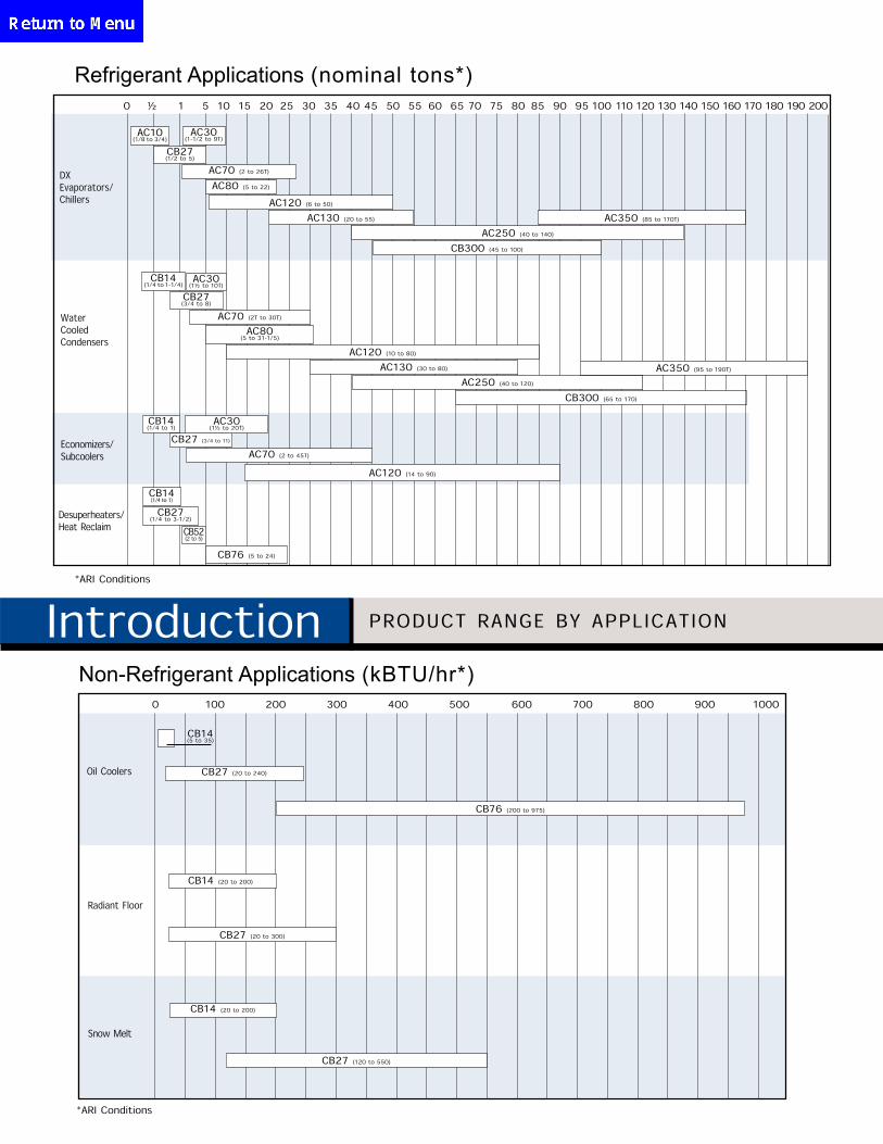
Introduction PRODUCT RANGE BY APPLICATION
*ARI Conditions
Non-Refrigerant Applications (kBTU/hr*)0 100 200 300 400 500 600 700 800 900 1000
Oil Coolers
Radiant Floor
Snow Melt
CB27 (20 to 240)
CB76 (200 to 975)
CB27 (20 to 300)
CB14 (20 to 200)
CB27 (120 to 550)
CB14(5 to 35)
CB14 (20 to 200)
Refrigerant Applications (nominal tons*)
DXEvaporators/Chillers
Water Cooled Condensers
Economizers/ Subcoolers
Desuperheaters/Heat Reclaim
AC10(1/8 to 3/4)
CB27(1/2 to 5)
AC70 (2 to 26T)
AC120 (6 to 50)
AC130 (20 to 55)
AC250 (40 to 140)
CB300 (45 to 100)
CB14(1/4 to 1-1/4)
CB27(3/4 to 8)
AC70 (2T to 30T)
AC120 (10 to 80)
CB14(1/4 to 1)
CB27 (3/4 to 11)
AC70 (2 to 45T)
AC120 (14 to 90)
CB14(1/4 to 1)
CB27(1/4 to 3-1/2)
CB52(2 to 5)
CB76 (5 to 24)
AC130 (30 to 80)
AC250 (40 to 120)
CB300 (65 to 170)
AC80 (5 to 22)
AC80(5 to 31-1/5)
*ARI Conditions
AC30(1-1/2 to 9T)
AC350 (85 to 170T)
0 ½ 1 5 10 15 20 25 30 35 40 45 50 55 60 65 70 75 80 85 90 95 100 110 120 130 140 150 160 170 180 190 200
AC30(1½ to 10T)
AC350 (95 to 190T)
AC30(1½ to 20T)
DX Evaporators/Chillers
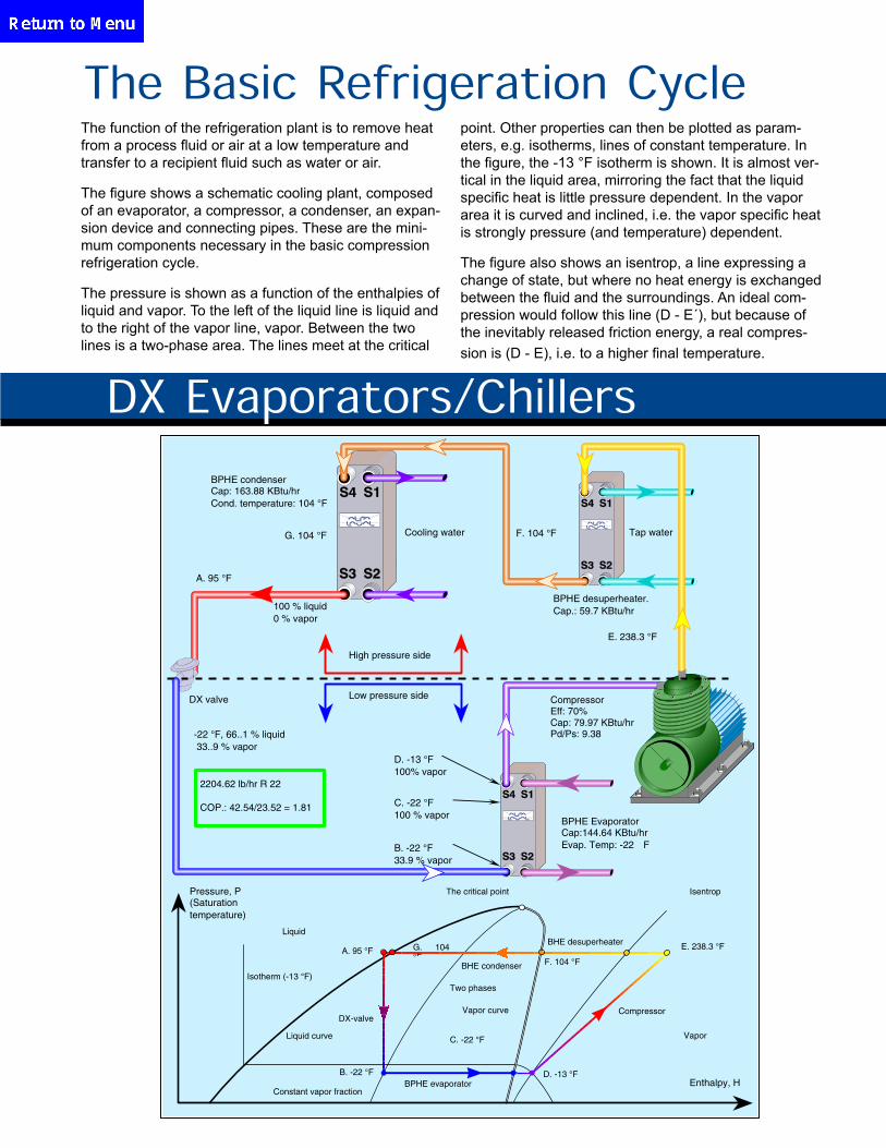
The function of the refrigeration plant is to remove heat from a process fluid or air at a low temperature and transfer to a recipient fluid such as water or air.
The figure shows a schematic cooling plant, composed of an evaporator, a compressor, a condenser, an expan-sion device and connecting pipes. These are the mini-mum components necessary in the basic compression refrigeration cycle.
The pressure is shown as a function of the enthalpies of liquid and vapor. To the left of the liquid line is liquid and to the right of the vapor line, vapor. Between the two lines is a two-phase area. The lines meet at the critical
point. Other properties can then be plotted as param-eters, e.g. isotherms, lines of constant temperature. In the figure, the -13 °F isotherm is shown. It is almost ver-tical in the liquid area, mirroring the fact that the liquid specific heat is little pressure dependent. In the vapor area it is curved and inclined, i.e. the vapor specific heat is strongly pressure (and temperature) dependent.
The figure also shows an isentrop, a line expressing a change of state, but where no heat energy is exchanged between the fluid and the surroundings. An ideal com-pression would follow this line (D - E´), but because of the inevitably released friction energy, a real compres-sion is (D - E), i.e. to a higher final temperature.
The Basic Refrigeration Cycle
2204.62 lb/hr R 22
COP.: 42.54/23.52 = 1.81
F. 104 °F
E. 238.3 °F
Compressor
-22 °F, 66..1 % liquid 33..9 % vapor
B. -22 °F 33.9 % vapor
C. -22 °F100 % vapor
D. -13 °F 100% vapor
Isentrop
G. 104 °F
Pressure, P (Saturation temperature)
Isotherm (-13 °F)
Liquid
The critical point
BPHE evaporator Enthalpy, H
Vapor
B. -22 °F
C. -22 °F
D. -13 °F
Two phases
Liquid curve
Vapor curve
A. 95 °F G. 104 °F
Constant vapor fraction
DX-valve
BHE condenser
BHE desuperheater
BPHE condenser Cap: 163.88 KBtu/hr Cond. temperature: 104 °F
Cooling water
BPHE desuperheater. Cap.: 59.7 KBtu/hr
Low pressure side
Tap water F. 104 °F
100 % liquid 0 % vapor
E. 238.3 °F
High pressure side
A. 95 °F
DX valve Compressor Eff: 70% Cap: 79.97 KBtu/hr Pd/Ps: 9.38
BPHE Evaporator Cap:144.64 KBtu/hr Evap. Temp: -22 F
DX Evaporators/Chillers
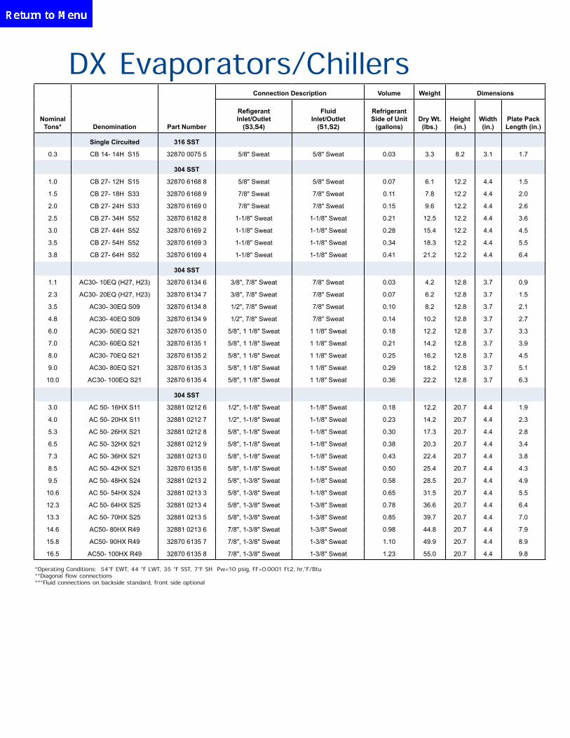
*Operating Conditions: 54°F EWT, 44 °F LWT, 35 °F SST, 7°F SH ∆Pw<10 psig, FF=0.0001 Ft2, hr,°F/Btu**Diagonal flow connections***Fluid connections on backside standard, front side optional
Connection Description Volume Weight Dimensions
Nominal Tons* Denomination Part Number
Refigerant Inlet/Outlet
(S3,S4)
Fluid Inlet/Outlet
(S1,S2)
Refrigerant Side of Unit
(gallons)Dry Wt. (lbs.)
Height (in.)
Width (in.)
Plate Pack Length (in.)
Single Circuited 316 SST
0.3 CB 14- 14H S15 32870 0075 5 5/8" Sweat 5/8" Sweat 0.03 3.3 8.2 3.1 1.7
304 SST
1.0 CB 27- 12H S15 32870 6168 8 5/8" Sweat 5/8" Sweat 0.07 6.1 12.2 4.4 1.5
1.5 CB 27- 18H S33 32870 6168 9 7/8" Sweat 7/8" Sweat 0.11 7.8 12.2 4.4 2.0
2.0 CB 27- 24H S33 32870 6169 0 7/8" Sweat 7/8" Sweat 0.15 9.6 12.2 4.4 2.6
2.5 CB 27- 34H S52 32870 6182 8 1-1/8" Sweat 1-1/8" Sweat 0.21 12.5 12.2 4.4 3.6
3.0 CB 27- 44H S52 32870 6169 2 1-1/8" Sweat 1-1/8" Sweat 0.28 15.4 12.2 4.4 4.5
3.5 CB 27- 54H S52 32870 6169 3 1-1/8" Sweat 1-1/8" Sweat 0.34 18.3 12.2 4.4 5.5
3.8 CB 27- 64H S52 32870 6169 4 1-1/8" Sweat 1-1/8" Sweat 0.41 21.2 12.2 4.4 6.4
304 SST
1.1 AC30- 10EQ (H27, H23) 32870 6134 6 3/8", 7/8" Sweat 7/8" Sweat 0.03 4.2 12.8 3.7 0.9
2.3 AC30- 20EQ (H27, H23) 32870 6134 7 3/8", 7/8" Sweat 7/8" Sweat 0.07 6.2 12.8 3.7 1.5
3.5 AC30- 30EQ S09 32870 6134 8 1/2", 7/8" Sweat 7/8" Sweat 0.10 8.2 12.8 3.7 2.1
4.8 AC30- 40EQ S09 32870 6134 9 1/2", 7/8" Sweat 7/8" Sweat 0.14 10.2 12.8 3.7 2.7
6.0 AC30- 50EQ S21 32870 6135 0 5/8", 1 1/8" Sweat 1 1/8" Sweat 0.18 12.2 12.8 3.7 3.3
7.0 AC30- 60EQ S21 32870 6135 1 5/8", 1 1/8" Sweat 1 1/8" Sweat 0.21 14.2 12.8 3.7 3.9
8.0 AC30- 70EQ S21 32870 6135 2 5/8", 1 1/8" Sweat 1 1/8" Sweat 0.25 16.2 12.8 3.7 4.5
9.0 AC30- 80EQ S21 32870 6135 3 5/8", 1 1/8" Sweat 1 1/8" Sweat 0.29 18.2 12.8 3.7 5.1
10.0 AC30- 100EQ S21 32870 6135 4 5/8", 1 1/8" Sweat 1 1/8" Sweat 0.36 22.2 12.8 3.7 6.3
304 SST
3.0 AC 50- 16HX S11 32881 0212 6 1/2", 1-1/8" Sweat 1-1/8" Sweat 0.18 12.2 20.7 4.4 1.9
4.0 AC 50- 20HX S11 32881 0212 7 1/2", 1-1/8" Sweat 1-1/8" Sweat 0.23 14.2 20.7 4.4 2.3
5.3 AC 50- 26HX S21 32881 0212 8 5/8", 1-1/8" Sweat 1-1/8" Sweat 0.30 17.3 20.7 4.4 2.8
6.5 AC 50- 32HX S21 32881 0212 9 5/8", 1-1/8" Sweat 1-1/8" Sweat 0.38 20.3 20.7 4.4 3.4
7.3 AC 50- 36HX S21 32881 0213 0 5/8", 1-1/8" Sweat 1-1/8" Sweat 0.43 22.4 20.7 4.4 3.8
8.5 AC 50- 42HX S21 32870 6135 6 5/8", 1-1/8" Sweat 1-1/8" Sweat 0.50 25.4 20.7 4.4 4.3
9.5 AC 50- 48HX S24 32881 0213 2 5/8", 1-3/8" Sweat 1-1/8" Sweat 0.58 28.5 20.7 4.4 4.9
10.6 AC 50- 54HX S24 32881 0213 3 5/8", 1-3/8" Sweat 1-1/8" Sweat 0.65 31.5 20.7 4.4 5.5
12.3 AC 50- 64HX S25 32881 0213 4 5/8", 1-3/8" Sweat 1-3/8" Sweat 0.78 36.6 20.7 4.4 6.4
13.3 AC 50- 70HX S25 32881 0213 5 5/8", 1-3/8" Sweat 1-3/8" Sweat 0.85 39.7 20.7 4.4 7.0
14.6 AC50- 80HX R49 32881 0213 6 7/8", 1-3/8" Sweat 1-3/8" Sweat 0.98 44.8 20.7 4.4 7.9
15.8 AC50- 90HX R49 32870 6135 7 7/8", 1-3/8" Sweat 1-3/8" Sweat 1.10 49.9 20.7 4.4 8.9
16.5 AC50- 100HX R49 32870 6135 8 7/8", 1-3/8" Sweat 1-3/8" Sweat 1.23 55.0 20.7 4.4 9.8
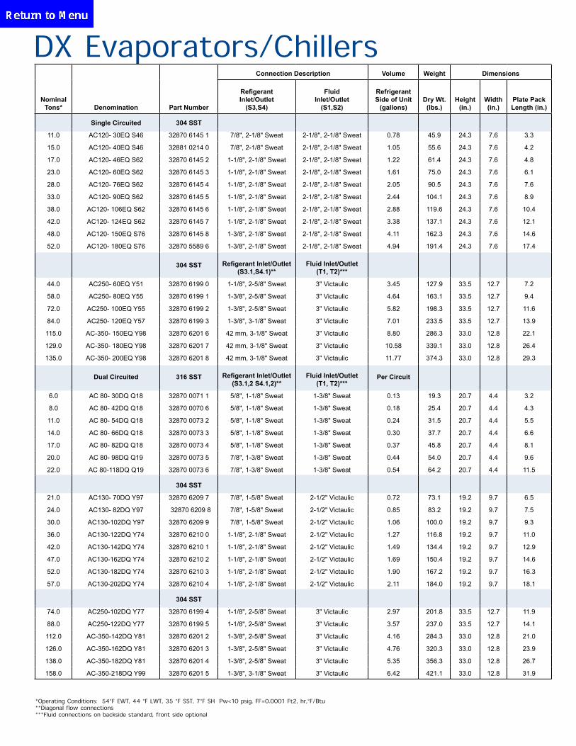
DX Evaporators/Chillers
*Operating Conditions: 54°F EWT, 44 °F LWT, 35 °F SST, 7°F SH ∆Pw<10 psig, FF=0.0001 Ft2, hr,°F/Btu**Diagonal flow connections***Fluid connections on backside standard, front side optional
Connection Description Volume Weight Dimensions
Nominal Tons* Denomination Part Number
Refigerant Inlet/Outlet
(S3,S4)
Fluid Inlet/Outlet
(S1,S2)
Refrigerant Side of Unit
(gallons)Dry Wt. (lbs.)
Height (in.)
Width (in.)
Plate Pack Length (in.)
Single Circuited 304 SST
11.0 AC120- 30EQ S46 32870 6145 1 7/8", 2-1/8" Sweat 2-1/8", 2-1/8" Sweat 0.78 45.9 24.3 7.6 3.3
15.0 AC120- 40EQ S46 32881 0214 0 7/8", 2-1/8" Sweat 2-1/8", 2-1/8" Sweat 1.05 55.6 24.3 7.6 4.2
17.0 AC120- 46EQ S62 32870 6145 2 1-1/8", 2-1/8" Sweat 2-1/8", 2-1/8" Sweat 1.22 61.4 24.3 7.6 4.8
23.0 AC120- 60EQ S62 32870 6145 3 1-1/8", 2-1/8" Sweat 2-1/8", 2-1/8" Sweat 1.61 75.0 24.3 7.6 6.1
28.0 AC120- 76EQ S62 32870 6145 4 1-1/8", 2-1/8" Sweat 2-1/8", 2-1/8" Sweat 2.05 90.5 24.3 7.6 7.6
33.0 AC120- 90EQ S62 32870 6145 5 1-1/8", 2-1/8" Sweat 2-1/8", 2-1/8" Sweat 2.44 104.1 24.3 7.6 8.9
38.0 AC120- 106EQ S62 32870 6145 6 1-1/8", 2-1/8" Sweat 2-1/8", 2-1/8" Sweat 2.88 119.6 24.3 7.6 10.4
42.0 AC120- 124EQ S62 32870 6145 7 1-1/8", 2-1/8" Sweat 2-1/8", 2-1/8" Sweat 3.38 137.1 24.3 7.6 12.1
48.0 AC120- 150EQ S76 32870 6145 8 1-3/8", 2-1/8" Sweat 2-1/8", 2-1/8" Sweat 4.11 162.3 24.3 7.6 14.6
52.0 AC120- 180EQ S76 32870 5589 6 1-3/8", 2-1/8" Sweat 2-1/8", 2-1/8" Sweat 4.94 191.4 24.3 7.6 17.4
304 SST Refigerant Inlet/Outlet (S3.1,S4.1)**
Fluid Inlet/Outlet (T1, T2)***
44.0 AC250- 60EQ Y51 32870 6199 0 1-1/8", 2-5/8" Sweat 3" Victaulic 3.45 127.9 33.5 12.7 7.2
58.0 AC250- 80EQ Y55 32870 6199 1 1-3/8", 2-5/8" Sweat 3" Victaulic 4.64 163.1 33.5 12.7 9.4
72.0 AC250- 100EQ Y55 32870 6199 2 1-3/8", 2-5/8" Sweat 3" Victaulic 5.82 198.3 33.5 12.7 11.6
84.0 AC250- 120EQ Y57 32870 6199 3 1-3/8", 3-1/8" Sweat 3" Victaulic 7.01 233.5 33.5 12.7 13.9
115.0 AC-350- 150EQ Y98 32870 6201 6 42 mm, 3-1/8" Sweat 3" Victaulic 8.80 286.3 33.0 12.8 22.1
129.0 AC-350- 180EQ Y98 32870 6201 7 42 mm, 3-1/8" Sweat 3" Victaulic 10.58 339.1 33.0 12.8 26.4
135.0 AC-350- 200EQ Y98 32870 6201 8 42 mm, 3-1/8" Sweat 3" Victaulic 11.77 374.3 33.0 12.8 29.3
Dual Circuited 316 SST Refigerant Inlet/Outlet (S3.1,2 S4.1,2)**
Fluid Inlet/Outlet (T1, T2)***
Per Circuit
6.0 AC 80- 30DQ Q18 32870 0071 1 5/8", 1-1/8" Sweat 1-3/8" Sweat 0.13 19.3 20.7 4.4 3.2
8.0 AC 80- 42DQ Q18 32870 0070 6 5/8", 1-1/8" Sweat 1-3/8" Sweat 0.18 25.4 20.7 4.4 4.3
11.0 AC 80- 54DQ Q18 32870 0073 2 5/8", 1-1/8" Sweat 1-3/8" Sweat 0.24 31.5 20.7 4.4 5.5
14.0 AC 80- 66DQ Q18 32870 0073 3 5/8", 1-1/8" Sweat 1-3/8" Sweat 0.30 37.7 20.7 4.4 6.6
17.0 AC 80- 82DQ Q18 32870 0073 4 5/8", 1-1/8" Sweat 1-3/8" Sweat 0.37 45.8 20.7 4.4 8.1
20.0 AC 80- 98DQ Q19 32870 0073 5 7/8", 1-3/8" Sweat 1-3/8" Sweat 0.44 54.0 20.7 4.4 9.6
22.0 AC 80-118DQ Q19 32870 0073 6 7/8", 1-3/8" Sweat 1-3/8" Sweat 0.54 64.2 20.7 4.4 11.5
304 SST
21.0 AC130- 70DQ Y97 32870 6209 7 7/8", 1-5/8" Sweat 2-1/2" Victaulic 0.72 73.1 19.2 9.7 6.5
24.0 AC130- 82DQ Y97 32870 6209 8 7/8", 1-5/8" Sweat 2-1/2" Victaulic 0.85 83.2 19.2 9.7 7.5
30.0 AC130-102DQ Y97 32870 6209 9 7/8", 1-5/8" Sweat 2-1/2" Victaulic 1.06 100.0 19.2 9.7 9.3
36.0 AC130-122DQ Y74 32870 6210 0 1-1/8", 2-1/8" Sweat 2-1/2" Victaulic 1.27 116.8 19.2 9.7 11.0
42.0 AC130-142DQ Y74 32870 6210 1 1-1/8", 2-1/8" Sweat 2-1/2" Victaulic 1.49 134.4 19.2 9.7 12.9
47.0 AC130-162DQ Y74 32870 6210 2 1-1/8", 2-1/8" Sweat 2-1/2" Victaulic 1.69 150.4 19.2 9.7 14.6
52.0 AC130-182DQ Y74 32870 6210 3 1-1/8", 2-1/8" Sweat 2-1/2" Victaulic 1.90 167.2 19.2 9.7 16.3
57.0 AC130-202DQ Y74 32870 6210 4 1-1/8", 2-1/8" Sweat 2-1/2" Victaulic 2.11 184.0 19.2 9.7 18.1
304 SST
74.0 AC250-102DQ Y77 32870 6199 4 1-1/8", 2-5/8" Sweat 3" Victaulic 2.97 201.8 33.5 12.7 11.9
88.0 AC250-122DQ Y77 32870 6199 5 1-1/8", 2-5/8" Sweat 3" Victaulic 3.57 237.0 33.5 12.7 14.1
112.0 AC-350-142DQ Y81 32870 6201 2 1-3/8", 2-5/8" Sweat 3" Victaulic 4.16 284.3 33.0 12.8 21.0
126.0 AC-350-162DQ Y81 32870 6201 3 1-3/8", 2-5/8" Sweat 3" Victaulic 4.76 320.3 33.0 12.8 23.9
138.0 AC-350-182DQ Y81 32870 6201 4 1-3/8", 2-5/8" Sweat 3" Victaulic 5.35 356.3 33.0 12.8 26.7
158.0 AC-350-218DQ Y99 32870 6201 5 1-3/8", 3-1/8" Sweat 3" Victaulic 6.42 421.1 33.0 12.8 31.9
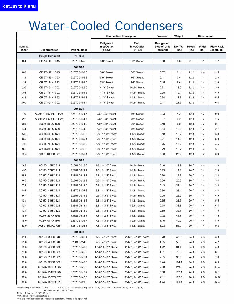
Water-Cooled Condensers
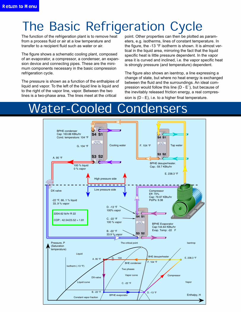
The function of the refrigeration plant is to remove heat from a process fluid or air at a low temperature and transfer to a recipient fluid such as water or air.
The figure shows a schematic cooling plant, composed of an evaporator, a compressor, a condenser, an expan-sion device and connecting pipes. These are the mini-mum components necessary in the basic compression refrigeration cycle.
The pressure is shown as a function of the enthalpies of liquid and vapor. To the left of the liquid line is liquid and to the right of the vapor line, vapor. Between the two lines is a two-phase area. The lines meet at the critical
point. Other properties can then be plotted as param-eters, e.g. isotherms, lines of constant temperature. In the figure, the -13 °F isotherm is shown. It is almost ver-tical in the liquid area, mirroring the fact that the liquid specific heat is little pressure dependent. In the vapor area it is curved and inclined, i.e. the vapor specific heat is strongly pressure (and temperature) dependent.
The figure also shows an isentrop, a line expressing a change of state, but where no heat energy is exchanged between the fluid and the surroundings. An ideal com-pression would follow this line (D - E´), but because of the inevitably released friction energy, a real compres-sion is (D - E), i.e. to a higher final temperature.
The Basic Refrigeration Cycle
2204.62 lb/hr R 22
COP.: 42.54/23.52 = 1.81
F. 104 °F
E. 238.3 °F
Compressor
-22 °F, 66..1 % liquid 33..9 % vapor
B. -22 °F 33.9 % vapor
C. -22 °F100 % vapor
D. -13 °F 100% vapor
Isentrop
G. 104 °F
Pressure, P (Saturation temperature)
Isotherm (-13 °F)
Liquid
The critical point
BPHE evaporator Enthalpy, H
Vapor
B. -22 °F
C. -22 °F
D. -13 °F
Two phases
Liquid curve
Vapor curve
A. 95 °F G. 104 °F
Constant vapor fraction
DX-valve
BHE condenser
BHE desuperheater
BPHE condenser Cap: 163.88 KBtu/hr Cond. temperature: 104 °F
Cooling water
BPHE desuperheater. Cap.: 59.7 KBtu/hr
Low pressure side
Tap water F. 104 °F
100 % liquid 0 % vapor
E. 238.3 °F
High pressure side
A. 95 °F
DX valve Compressor Eff: 70% Cap: 79.97 KBtu/hr Pd/Ps: 9.38
BPHE Evaporator Cap:144.64 KBtu/hr Evap. Temp: -22 F
Water-Cooled Condensers
*Operating Conditions: 195°F EGT, 105°F SCT, 5°F Subcooling, 85°F EWT, 95°F LWT, ∆Pref<5 psig, ∆Pw<10 psig, FF=0.0001 Ft2, hr,°F/Btu Note: 1 Ton = 15,000 Btu/hr. **Diagonal flow connections ***Fluid connections on backside standard, front side optional
Connection Description Volume Weight Dimensions
Nominal Tons* Denomination Part Number
Refigerant Inlet/Outlet
(S3,S4)
Fluid Inlet/Outlet
(S1,S2)
RefrigerantSide of Unit
(gallons)Dry Wt. (lbs.)
Height (in.)
Width (in.)
Plate Pack Length (in.)
Single Circuited 316 SST
0.4 CB 14- 14H S15 32870 0075 5 5/8" Sweat 5/8" Sweat 0.03 3.3 8.2 3.1 1.7
304 SST
0.8 CB 27- 12H S15 32870 6168 8 5/8" Sweat 5/8" Sweat 0.07 6.1 12.2 4.4 1.5
1.3 CB 27- 18H S33 32870 6168 9 7/8" Sweat 7/8" Sweat 0.11 7.8 12.2 4.4 2.0
1.8 CB 27- 24H S33 32870 6169 0 7/8" Sweat 7/8" Sweat 0.15 9.6 12.2 4.4 2.6
2.6 CB 27- 34H S52 32870 6182 8 1-1/8" Sweat 1-1/8" Sweat 0.21 12.5 12.2 4.4 3.6
3.4 CB 27- 44H S52 32870 6169 2 1-1/8" Sweat 1-1/8" Sweat 0.28 15.4 12.2 4.4 4.5
4.2 CB 27- 54H S52 32870 6169 3 1-1/8" Sweat 1-1/8" Sweat 0.34 18.3 12.2 4.4 5.5
5.0 CB 27- 64H S52 32870 6169 4 1-1/8" Sweat 1-1/8" Sweat 0.41 21.2 12.2 4.4 6.4
304 SST
1.0 AC30- 10EQ (H27, H23) 32870 6134 6 3/8", 7/8" Sweat 7/8" Sweat 0.03 4.2 12.8 3.7 0.9
2.2 AC30- 20EQ (H27, H23) 32870 6134 7 3/8", 7/8" Sweat 7/8" Sweat 0.07 6.2 12.8 3.7 1.5
3.3 AC30- 30EQ S09 32870 6134 8 1/2", 7/8" Sweat 7/8" Sweat 0.10 8.2 12.8 3.7 2.1
4.4 AC30- 40EQ S09 32870 6134 9 1/2", 7/8" Sweat 7/8" Sweat 0.14 10.2 12.8 3.7 2.7
5.6 AC30- 50EQ S21 32870 6135 0 5/8", 1 1/8" Sweat 1 1/8" Sweat 0.18 12.2 12.8 3.7 3.3
6.5 AC30- 60EQ S21 32870 6135 1 5/8", 1 1/8" Sweat 1 1/8" Sweat 0.21 14.2 12.8 3.7 3.9
7.6 AC30- 70EQ S21 32870 6135 2 5/8", 1 1/8" Sweat 1 1/8" Sweat 0.25 16.2 12.8 3.7 4.5
8.5 AC30- 80EQ S21 32870 6135 3 5/8", 1 1/8" Sweat 1 1/8" Sweat 0.29 18.2 12.8 3.7 5.1
10.4 AC30- 100EQ S21 32870 6135 4 5/8", 1 1/8" Sweat 1 1/8" Sweat 0.36 22.2 12.8 3.7 6.3
304 SST
3.2 AC 50- 16HX S11 32881 0212 6 1/2", 1-1/8" Sweat 1-1/8" Sweat 0.18 12.2 20.7 4.4 1.9
4.0 AC 50- 20HX S11 32881 0212 7 1/2", 1-1/8" Sweat 1-1/8" Sweat 0.23 14.2 20.7 4.4 2.3
5.3 AC 50- 26HX S21 32881 0212 8 5/8", 1-1/8" Sweat 1-1/8" Sweat 0.30 17.3 20.7 4.4 2.8
6.5 AC 50- 32HX S21 32881 0212 9 5/8", 1-1/8" Sweat 1-1/8" Sweat 0.38 20.3 20.7 4.4 3.4
7.3 AC 50- 36HX S21 32881 0213 0 5/8", 1-1/8" Sweat 1-1/8" Sweat 0.43 22.4 20.7 4.4 3.8
8.5 AC 50- 42HX S21 32870 6135 6 5/8", 1-1/8" Sweat 1-1/8" Sweat 0.50 25.4 20.7 4.4 4.3
9.7 AC 50- 48HX S24 32881 0213 2 5/8", 1-3/8" Sweat 1-1/8" Sweat 0.58 28.5 20.7 4.4 4.9
10.8 AC 50- 54HX S24 32881 0213 3 5/8", 1-3/8" Sweat 1-1/8" Sweat 0.65 31.5 20.7 4.4 5.5
12.8 AC 50- 64HX S25 32881 0213 4 5/8", 1-3/8" Sweat 1-3/8" Sweat 0.78 36.6 20.7 4.4 6.4
13.8 AC 50- 70HX S25 32881 0213 5 5/8", 1-3/8" Sweat 1-3/8" Sweat 0.85 39.7 20.7 4.4 7.0
16.0 AC50- 80HX R49 32881 0213 6 7/8", 1-3/8" Sweat 1-3/8" Sweat 0.98 44.8 20.7 4.4 7.9
18.0 AC50- 90HX R49 32870 6135 7 7/8", 1-3/8" Sweat 1-3/8" Sweat 1.10 49.9 20.7 4.4 8.9
20.0 AC50- 100HX R49 32870 6135 8 7/8", 1-3/8" Sweat 1-3/8" Sweat 1.23 55.0 20.7 4.4 9.8
304 SST
11.0 AC120- 30EQ S46 32870 6145 1 7/8", 2-1/8" Sweat 2-1/8", 2-1/8" Sweat 0.78 45.9 24.3 7.6 3.3
15.0 AC120- 40EQ S46 32881 0214 0 7/8", 2-1/8" Sweat 2-1/8", 2-1/8" Sweat 1.05 55.6 24.3 7.6 4.2
18.0 AC120- 46EQ S62 32870 6145 2 1-1/8", 2-1/8" Sweat 2-1/8", 2-1/8" Sweat 1.22 61.4 24.3 7.6 4.8
23.0 AC120- 60EQ S62 32870 6145 3 1-1/8", 2-1/8" Sweat 2-1/8", 2-1/8" Sweat 1.61 75.0 24.3 7.6 6.1
29.0 AC120- 76EQ S62 32870 6145 4 1-1/8", 2-1/8" Sweat 2-1/8", 2-1/8" Sweat 2.05 90.5 24.3 7.6 7.6
35.0 AC120- 90EQ S62 32870 6145 5 1-1/8", 2-1/8" Sweat 2-1/8", 2-1/8" Sweat 2.44 104.1 24.3 7.6 8.9
40.0 AC120- 106EQ S62 32870 6145 6 1-1/8", 2-1/8" Sweat 2-1/8", 2-1/8" Sweat 2.88 119.6 24.3 7.6 10.4
46.0 AC120- 124EQ S62 32870 6145 7 1-1/8", 2-1/8" Sweat 2-1/8", 2-1/8" Sweat 3.38 137.1 24.3 7.6 12.1
56.0 AC120- 150EQ S76 32870 6145 8 1-3/8", 2-1/8" Sweat 2-1/8", 2-1/8" Sweat 4.11 162.3 24.3 7.6 14.6
66.0 AC120- 180EQ S76 32870 5589 6 1-3/8", 2-1/8" Sweat 2-1/8", 2-1/8" Sweat 4.94 191.4 24.3 7.6 17.4
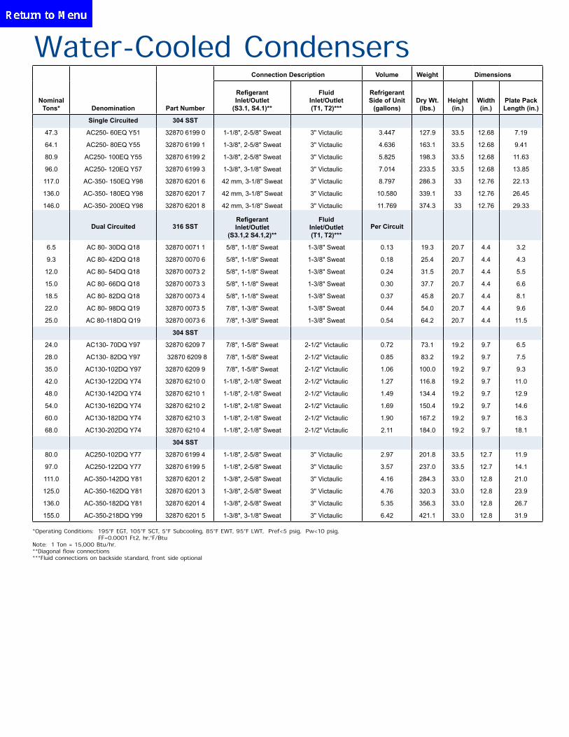
*Operating Conditions: 195°F EGT, 105°F SCT, 5°F Subcooling, 85°F EWT, 95°F LWT, ∆Pref<5 psig, ∆Pw<10 psig, FF=0.0001 Ft2, hr,°F/Btu Note: 1 Ton = 15,000 Btu/hr. **Diagonal flow connections ***Fluid connections on backside standard, front side optional
Water-Cooled CondensersConnection Description Volume Weight Dimensions
Nominal Tons* Denomination Part Number
Refigerant Inlet/Outlet
(S3.1, S4.1)**
Fluid Inlet/Outlet (T1, T2)***
Refrigerant Side of Unit
(gallons)Dry Wt. (lbs.)
Height (in.)
Width (in.)
Plate Pack Length (in.)
Single Circuited 304 SST
47.3 AC250- 60EQ Y51 32870 6199 0 1-1/8", 2-5/8" Sweat 3" Victaulic 3.447 127.9 33.5 12.68 7.19
64.1 AC250- 80EQ Y55 32870 6199 1 1-3/8", 2-5/8" Sweat 3" Victaulic 4.636 163.1 33.5 12.68 9.41
80.9 AC250- 100EQ Y55 32870 6199 2 1-3/8", 2-5/8" Sweat 3" Victaulic 5.825 198.3 33.5 12.68 11.63
96.0 AC250- 120EQ Y57 32870 6199 3 1-3/8", 3-1/8" Sweat 3" Victaulic 7.014 233.5 33.5 12.68 13.85
117.0 AC-350- 150EQ Y98 32870 6201 6 42 mm, 3-1/8" Sweat 3" Victaulic 8.797 286.3 33 12.76 22.13
136.0 AC-350- 180EQ Y98 32870 6201 7 42 mm, 3-1/8" Sweat 3" Victaulic 10.580 339.1 33 12.76 26.45
146.0 AC-350- 200EQ Y98 32870 6201 8 42 mm, 3-1/8" Sweat 3" Victaulic 11.769 374.3 33 12.76 29.33
Dual Circuited 316 SST Refigerant Inlet/Outlet
(S3.1,2 S4.1,2)**
Fluid Inlet/Outlet (T1, T2)***
Per Circuit
6.5 AC 80- 30DQ Q18 32870 0071 1 5/8", 1-1/8" Sweat 1-3/8" Sweat 0.13 19.3 20.7 4.4 3.2
9.3 AC 80- 42DQ Q18 32870 0070 6 5/8", 1-1/8" Sweat 1-3/8" Sweat 0.18 25.4 20.7 4.4 4.3
12.0 AC 80- 54DQ Q18 32870 0073 2 5/8", 1-1/8" Sweat 1-3/8" Sweat 0.24 31.5 20.7 4.4 5.5
15.0 AC 80- 66DQ Q18 32870 0073 3 5/8", 1-1/8" Sweat 1-3/8" Sweat 0.30 37.7 20.7 4.4 6.6
18.5 AC 80- 82DQ Q18 32870 0073 4 5/8", 1-1/8" Sweat 1-3/8" Sweat 0.37 45.8 20.7 4.4 8.1
22.0 AC 80- 98DQ Q19 32870 0073 5 7/8", 1-3/8" Sweat 1-3/8" Sweat 0.44 54.0 20.7 4.4 9.6
25.0 AC 80-118DQ Q19 32870 0073 6 7/8", 1-3/8" Sweat 1-3/8" Sweat 0.54 64.2 20.7 4.4 11.5
304 SST
24.0 AC130- 70DQ Y97 32870 6209 7 7/8", 1-5/8" Sweat 2-1/2" Victaulic 0.72 73.1 19.2 9.7 6.5
28.0 AC130- 82DQ Y97 32870 6209 8 7/8", 1-5/8" Sweat 2-1/2" Victaulic 0.85 83.2 19.2 9.7 7.5
35.0 AC130-102DQ Y97 32870 6209 9 7/8", 1-5/8" Sweat 2-1/2" Victaulic 1.06 100.0 19.2 9.7 9.3
42.0 AC130-122DQ Y74 32870 6210 0 1-1/8", 2-1/8" Sweat 2-1/2" Victaulic 1.27 116.8 19.2 9.7 11.0
48.0 AC130-142DQ Y74 32870 6210 1 1-1/8", 2-1/8" Sweat 2-1/2" Victaulic 1.49 134.4 19.2 9.7 12.9
54.0 AC130-162DQ Y74 32870 6210 2 1-1/8", 2-1/8" Sweat 2-1/2" Victaulic 1.69 150.4 19.2 9.7 14.6
60.0 AC130-182DQ Y74 32870 6210 3 1-1/8", 2-1/8" Sweat 2-1/2" Victaulic 1.90 167.2 19.2 9.7 16.3
68.0 AC130-202DQ Y74 32870 6210 4 1-1/8", 2-1/8" Sweat 2-1/2" Victaulic 2.11 184.0 19.2 9.7 18.1
304 SST
80.0 AC250-102DQ Y77 32870 6199 4 1-1/8", 2-5/8" Sweat 3" Victaulic 2.97 201.8 33.5 12.7 11.9
97.0 AC250-122DQ Y77 32870 6199 5 1-1/8", 2-5/8" Sweat 3" Victaulic 3.57 237.0 33.5 12.7 14.1
111.0 AC-350-142DQ Y81 32870 6201 2 1-3/8", 2-5/8" Sweat 3" Victaulic 4.16 284.3 33.0 12.8 21.0
125.0 AC-350-162DQ Y81 32870 6201 3 1-3/8", 2-5/8" Sweat 3" Victaulic 4.76 320.3 33.0 12.8 23.9
136.0 AC-350-182DQ Y81 32870 6201 4 1-3/8", 2-5/8" Sweat 3" Victaulic 5.35 356.3 33.0 12.8 26.7
155.0 AC-350-218DQ Y99 32870 6201 5 1-3/8", 3-1/8" Sweat 3" Victaulic 6.42 421.1 33.0 12.8 31.9
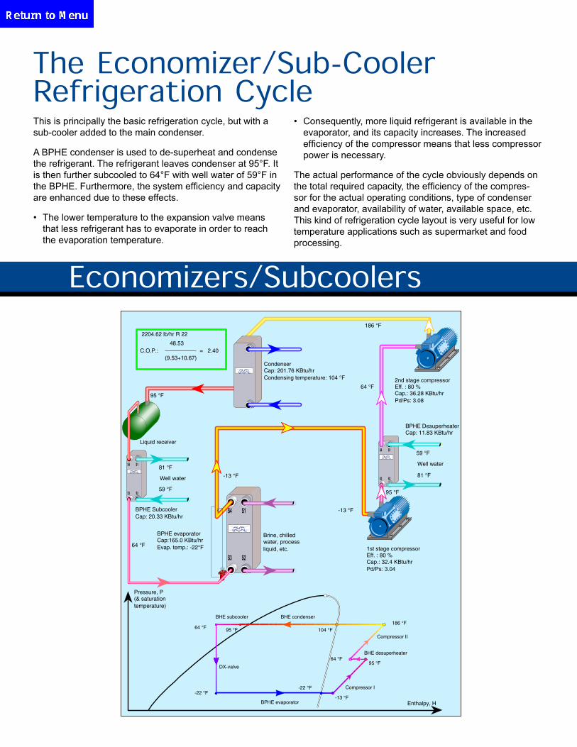
Economizers/Subcoolers
The Economizer/Sub-Cooler Refrigeration CycleThis is principally the basic refrigeration cycle, but with a sub-cooler added to the main condenser.
A BPHE condenser is used to de-superheat and condense the refrigerant. The refrigerant leaves condenser at 95°F. It is then further subcooled to 64°F with well water of 59°F in the BPHE. Furthermore, the system efficiency and capacity are enhanced due to these effects.
• The lower temperature to the expansion valve means that less refrigerant has to evaporate in order to reach the evaporation temperature.
• Consequently, more liquid refrigerant is available in the evaporator, and its capacity increases. The increased efficiency of the compressor means that less compressor power is necessary.
The actual performance of the cycle obviously depends on the total required capacity, the efficiency of the compres-sor for the actual operating conditions, type of condenser and evaporator, availability of water, available space, etc. This kind of refrigeration cycle layout is very useful for low temperature applications such as supermarket and food processing.
S4 S1
S3 S2
S4 S1
S3 S2
S4 S1
S3 S2
-13 °F
Brine, chilled water, process liquid, etc.
95 °F
Compressor II
64 °F
186 °F
-22 °F
64 °F
BHE condenser
BPHE evaporator
DX-valve
-22 °F
BHE desuperheater
104 °F
BHE subcooler
Compressor I
-13 °F
95 °F
Enthalpy, H
1st stage compressor Eff. : 80 % Cap.: 32.4 KBtu/hr Pd/Ps: 3.04
Pressure, P (& saturation temperature)
2nd stage compressor Eff. : 80 % Cap.: 36.28 KBtu/hr Pd/Ps: 3.08
59 °F
Well water
81 °F
Condenser Cap: 201.76 KBtu/hr Condensing temperature: 104 °F
BPHE evaporator Cap:165.0 KBtu/hr Evap. temp.: -22°F
81 °F
Well water
59 °F
64 °F
95 °F
186 °F
95 °F
64 °F
Liquid receiver
-13 °F
2204.62 lb/hr R 22
48.53 C.O.P.: = 2.40
(9.53+10.67)
BPHE Desuperheater Cap: 11.83 KBtu/hr
BPHE Subcooler Cap: 20.33 KBtu/hr
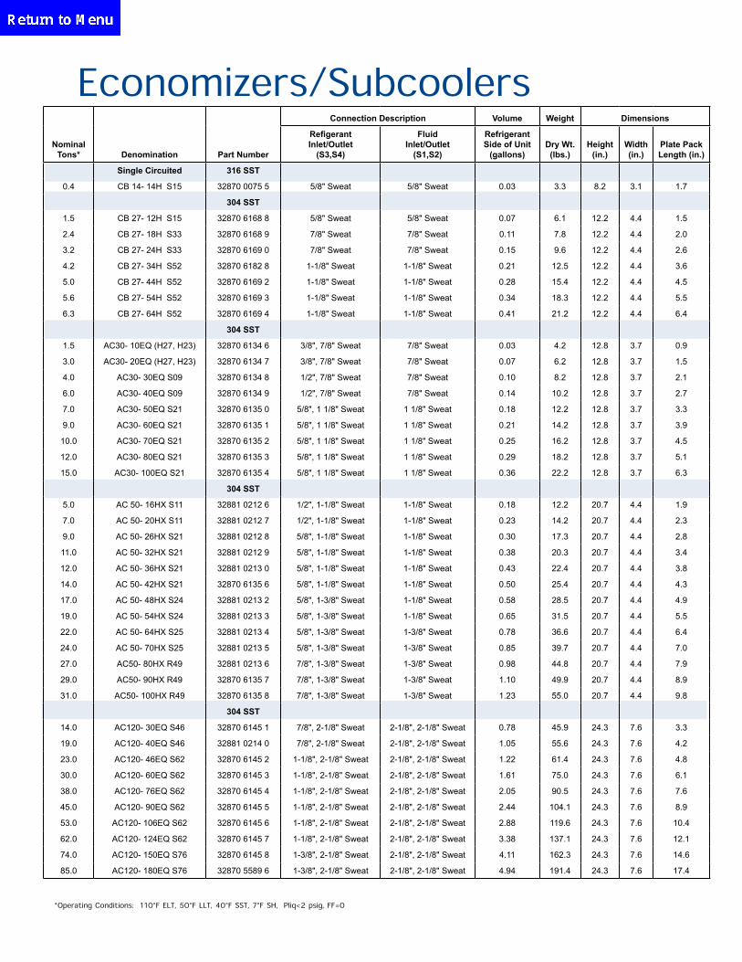
Economizers/Subcoolers
*Operating Conditions: 110°F ELT, 50°F LLT, 40°F SST, 7°F SH, ∆Pliq<2 psig, FF=0
Connection Description Volume Weight Dimensions
Nominal Tons* Denomination Part Number
Refigerant Inlet/Outlet
(S3,S4)
Fluid Inlet/Outlet
(S1,S2)
Refrigerant Side of Unit
(gallons)Dry Wt. (lbs.)
Height (in.)
Width (in.)
Plate Pack Length (in.)
Single Circuited 316 SST
0.4 CB 14- 14H S15 32870 0075 5 5/8" Sweat 5/8" Sweat 0.03 3.3 8.2 3.1 1.7
304 SST
1.5 CB 27- 12H S15 32870 6168 8 5/8" Sweat 5/8" Sweat 0.07 6.1 12.2 4.4 1.5
2.4 CB 27- 18H S33 32870 6168 9 7/8" Sweat 7/8" Sweat 0.11 7.8 12.2 4.4 2.0
3.2 CB 27- 24H S33 32870 6169 0 7/8" Sweat 7/8" Sweat 0.15 9.6 12.2 4.4 2.6
4.2 CB 27- 34H S52 32870 6182 8 1-1/8" Sweat 1-1/8" Sweat 0.21 12.5 12.2 4.4 3.6
5.0 CB 27- 44H S52 32870 6169 2 1-1/8" Sweat 1-1/8" Sweat 0.28 15.4 12.2 4.4 4.5
5.6 CB 27- 54H S52 32870 6169 3 1-1/8" Sweat 1-1/8" Sweat 0.34 18.3 12.2 4.4 5.5
6.3 CB 27- 64H S52 32870 6169 4 1-1/8" Sweat 1-1/8" Sweat 0.41 21.2 12.2 4.4 6.4
304 SST
1.5 AC30- 10EQ (H27, H23) 32870 6134 6 3/8", 7/8" Sweat 7/8" Sweat 0.03 4.2 12.8 3.7 0.9
3.0 AC30- 20EQ (H27, H23) 32870 6134 7 3/8", 7/8" Sweat 7/8" Sweat 0.07 6.2 12.8 3.7 1.5
4.0 AC30- 30EQ S09 32870 6134 8 1/2", 7/8" Sweat 7/8" Sweat 0.10 8.2 12.8 3.7 2.1
6.0 AC30- 40EQ S09 32870 6134 9 1/2", 7/8" Sweat 7/8" Sweat 0.14 10.2 12.8 3.7 2.7
7.0 AC30- 50EQ S21 32870 6135 0 5/8", 1 1/8" Sweat 1 1/8" Sweat 0.18 12.2 12.8 3.7 3.3
9.0 AC30- 60EQ S21 32870 6135 1 5/8", 1 1/8" Sweat 1 1/8" Sweat 0.21 14.2 12.8 3.7 3.9
10.0 AC30- 70EQ S21 32870 6135 2 5/8", 1 1/8" Sweat 1 1/8" Sweat 0.25 16.2 12.8 3.7 4.5
12.0 AC30- 80EQ S21 32870 6135 3 5/8", 1 1/8" Sweat 1 1/8" Sweat 0.29 18.2 12.8 3.7 5.1
15.0 AC30- 100EQ S21 32870 6135 4 5/8", 1 1/8" Sweat 1 1/8" Sweat 0.36 22.2 12.8 3.7 6.3
304 SST
5.0 AC 50- 16HX S11 32881 0212 6 1/2", 1-1/8" Sweat 1-1/8" Sweat 0.18 12.2 20.7 4.4 1.9
7.0 AC 50- 20HX S11 32881 0212 7 1/2", 1-1/8" Sweat 1-1/8" Sweat 0.23 14.2 20.7 4.4 2.3
9.0 AC 50- 26HX S21 32881 0212 8 5/8", 1-1/8" Sweat 1-1/8" Sweat 0.30 17.3 20.7 4.4 2.8
11.0 AC 50- 32HX S21 32881 0212 9 5/8", 1-1/8" Sweat 1-1/8" Sweat 0.38 20.3 20.7 4.4 3.4
12.0 AC 50- 36HX S21 32881 0213 0 5/8", 1-1/8" Sweat 1-1/8" Sweat 0.43 22.4 20.7 4.4 3.8
14.0 AC 50- 42HX S21 32870 6135 6 5/8", 1-1/8" Sweat 1-1/8" Sweat 0.50 25.4 20.7 4.4 4.3
17.0 AC 50- 48HX S24 32881 0213 2 5/8", 1-3/8" Sweat 1-1/8" Sweat 0.58 28.5 20.7 4.4 4.9
19.0 AC 50- 54HX S24 32881 0213 3 5/8", 1-3/8" Sweat 1-1/8" Sweat 0.65 31.5 20.7 4.4 5.5
22.0 AC 50- 64HX S25 32881 0213 4 5/8", 1-3/8" Sweat 1-3/8" Sweat 0.78 36.6 20.7 4.4 6.4
24.0 AC 50- 70HX S25 32881 0213 5 5/8", 1-3/8" Sweat 1-3/8" Sweat 0.85 39.7 20.7 4.4 7.0
27.0 AC50- 80HX R49 32881 0213 6 7/8", 1-3/8" Sweat 1-3/8" Sweat 0.98 44.8 20.7 4.4 7.9
29.0 AC50- 90HX R49 32870 6135 7 7/8", 1-3/8" Sweat 1-3/8" Sweat 1.10 49.9 20.7 4.4 8.9
31.0 AC50- 100HX R49 32870 6135 8 7/8", 1-3/8" Sweat 1-3/8" Sweat 1.23 55.0 20.7 4.4 9.8
304 SST
14.0 AC120- 30EQ S46 32870 6145 1 7/8", 2-1/8" Sweat 2-1/8", 2-1/8" Sweat 0.78 45.9 24.3 7.6 3.3
19.0 AC120- 40EQ S46 32881 0214 0 7/8", 2-1/8" Sweat 2-1/8", 2-1/8" Sweat 1.05 55.6 24.3 7.6 4.2
23.0 AC120- 46EQ S62 32870 6145 2 1-1/8", 2-1/8" Sweat 2-1/8", 2-1/8" Sweat 1.22 61.4 24.3 7.6 4.8
30.0 AC120- 60EQ S62 32870 6145 3 1-1/8", 2-1/8" Sweat 2-1/8", 2-1/8" Sweat 1.61 75.0 24.3 7.6 6.1
38.0 AC120- 76EQ S62 32870 6145 4 1-1/8", 2-1/8" Sweat 2-1/8", 2-1/8" Sweat 2.05 90.5 24.3 7.6 7.6
45.0 AC120- 90EQ S62 32870 6145 5 1-1/8", 2-1/8" Sweat 2-1/8", 2-1/8" Sweat 2.44 104.1 24.3 7.6 8.9
53.0 AC120- 106EQ S62 32870 6145 6 1-1/8", 2-1/8" Sweat 2-1/8", 2-1/8" Sweat 2.88 119.6 24.3 7.6 10.4
62.0 AC120- 124EQ S62 32870 6145 7 1-1/8", 2-1/8" Sweat 2-1/8", 2-1/8" Sweat 3.38 137.1 24.3 7.6 12.1
74.0 AC120- 150EQ S76 32870 6145 8 1-3/8", 2-1/8" Sweat 2-1/8", 2-1/8" Sweat 4.11 162.3 24.3 7.6 14.6
85.0 AC120- 180EQ S76 32870 5589 6 1-3/8", 2-1/8" Sweat 2-1/8", 2-1/8" Sweat 4.94 191.4 24.3 7.6 17.4
Desuperheaters/Heat Reclaim
S4 S1
S3 S2
S4 S1
S3 S2
S4 S1
S3 S2
-13 °F
Brine, chilled water, process liquid, etc.
95 °F
Compressor II
64 °F
186 °F
-22 °F
64 °F
BHE condenser
BPHE evaporator
DX-valve
-22 °F
BHE desuperheater
104 °F
BHE subcooler
Compressor I
-13 °F
95 °F
Enthalpy, H
1st stage compressor Eff. : 80 % Cap.: 32.4 KBtu/hr Pd/Ps: 3.04
Pressure, P (& saturation temperature)
2nd stage compressor Eff. : 80 % Cap.: 36.28 KBtu/hr Pd/Ps: 3.08
59 °F
Well water
81 °F
Condenser Cap: 201.76 KBtu/hr Condensing temperature: 104 °F
BPHE evaporator Cap:165.0 KBtu/hr Evap. temp.: -22°F
81 °F
Well water
59 °F
64 °F
95 °F
186 °F
95 °F
64 °F
Liquid receiver
-13 °F
2204.62 lb/hr R 22
48.53 C.O.P.: = 2.40
(9.53+10.67)
BPHE Desuperheater Cap: 11.83 KBtu/hr
BPHE Subcooler Cap: 20.33 KBtu/hr
This is principally the basic refrigeration cycle, but with a desu-perheater/heat re-claimer introduced between the compressor stages.
A further improvement is the use of a two-stage compression, either with two compressors in series or in a two-stage com-pressor. The desuperheater between the compressor stages is only possible for a compressor where the first stage vapor leaves the first stage and then enters the second stage, pos-
sibly together with additional intermediate pressure vapor but not for a compressor with only an intermediate vapor inlet.
The first stage vapor leaves at about 95°F and is cooled in the BPHE at about 64°F also with well water. The higher vapor density increases the amount of refrigerant in the second stage i.e. higher capacity. The higher vapor density decreases the refrigerant volume in the second stage, i.e. a smaller compressor.
The De-super Heater/Heat Reclaim Refrigeration Cycle
De-superheaters/Heat Reclaim
*Operating Conditions: 180°F EGT, 90°F EWT, 140°F LWT, ∆Pref<2 psig, ∆Pw<10 psig, FF=0.0001 Ft2, hr,°F/Btu
Connection Description Volume Weight Dimensions
Nominal Tons* Denomination Part Number
Refigerant Inlet/Outlet
(S3,S4)
Fluid Inlet/Outlet
(S1,S2)
Refrigerant Side of Unit
(gallons)Dry Wt. (lbs.)
Height (in.)
Width (in.)
Plate Pack Length (in.)
Single Circuited 316 SST
0.5 CB 14- 14H S15 32870 0075 5 5/8" Sweat 5/8" Sweat 0.03 3.3 8.2 3.1 1.7
304 SST
0.5 CB 27- 12H S15 32870 6168 8 5/8" Sweat 5/8" Sweat 0.07 6.1 12.2 4.4 1.5
1.0 CB 27- 18H S33 32870 6168 9 7/8" Sweat 7/8" Sweat 0.11 7.8 12.2 4.4 2.0
1.5 CB 27- 24H S33 32870 6169 0 7/8" Sweat 7/8" Sweat 0.15 9.6 12.2 4.4 2.6
1.8 CB 27- 34H S52 32870 6182 8 1-1/8" Sweat 1-1/8" Sweat 0.21 12.5 12.2 4.4 3.6
2.3 CB 27- 44H S52 32870 6169 2 1-1/8" Sweat 1-1/8" Sweat 0.28 15.4 12.2 4.4 4.5
2.5 CB 27- 54H S52 32870 6169 3 1-1/8" Sweat 1-1/8" Sweat 0.34 18.3 12.2 4.4 5.5
3.3 CB 27- 64H S52 32870 6169 4 1-1/8" Sweat 1-1/8" Sweat 0.41 21.2 12.2 4.4 6.4
316 SST
2.0 **CB52-30L C65 CB52-30L C65 1-3/8" Sweat 1" Male NPT 0.35 19.2 20.7 4.4 3.2
3.0 **CB52-40L C65 CB52-40L C65 1-3/8" Sweat 1" Male NPT 0.48 24.3 20.7 4.4 4.2
4.0 **CB52-50L C65 CB52-50L C65 1-3/8" Sweat 1" Male NPT 0.60 29.3 20.7 4.4 5.1
4.5 **CB52-60L C65 CB52-60L C65 1-3/8" Sweat 1" Male NPT 0.73 34.4 20.7 4.4 6.0
5.0 **CB52-80L C65 CB52-80L C65 1-3/8" Sweat 1" Male NPT 0.98 44.5 20.7 4.4 7.9
316 SST
5.0 **CB76-24M-C79 CB76-24M-C79 1-5/8" Sweat 2" Male NPT 0.73 40.0 24.9 7.6 3.0
6.0 **CB76-30M-C79 CB76-30M-C79 1-5/8" Sweat 2" Male NPT 0.92 45.9 24.9 7.6 3.7
8.0 **CB76-40M-C79 CB76-40M-C79 2-1/8" Sweat 2" Male NPT 1.25 55.6 24.9 7.6 4.8
12.0 **CB76-50M-C79 CB76-50M-C79 2-1/8" Sweat 2" Male NPT 1.59 65.3 24.9 7.6 5.9
14.0 **CB76-60M-C79 CB76-60M-C79 2-1/8" Sweat 2" Male NPT 1.92 75.0 24.9 7.6 7.0
16.0 **CB76-72M-C79 CB76-72M-C79 2-1/8" Sweat 2" Male NPT 2.31 86.6 24.9 7.6 8.3
19.0 **CB76-90M-C79 CB76-90M-C79 2-1/8" Sweat 2" Male NPT 2.91 104.1 24.9 7.6 10.3
22.0 **CB76-110M-C79 CB76-110M-C79 2-1/8" Sweat 2" Male NPT 3.57 123.5 24.9 7.6 12.5
25.0 **CB76-150M-C79 CB76-150M-C79 2-1/8" Sweat 2" Male NPT 4.89 162.3 24.9 7.6 16.9
Hydraulic Oil Coolers
Oil cooler and oil return evaporator in flooded system with soluble oil.
Oil evaporator
Pressure drop creating valve.
Oil filter
Oil tank
Oil cooler 98.6 °F
98.6 °F
38.1 °F
28.4 °F
107.6/214.3°F
107.6/205.5 °F
106.7 °F
106.7/214.3 °F
V1
V2
EQL
Oil pump
LR
Condensate column
Vent
28.4 °F
28.4 °F
26.6/28.4 °F
26.6/29.8 F
The system is the same for both a soluble and an insoluble oil. The oil is cooled by evaporating warm condensate. The other possibilities, cold refrigerant or water, give larger thermal shocks.
After evaporation, the vapor is condensed in the condenser again. It returns to the condenser either via:a. the LR and the equalization line (EQL)b. directly back to the condenser inlet orc. back through the condensate pipe to the condenser exit and into the channels from below
The Oil Cooler
The vapor-liquid mixture leaving the evaporator enters the separator, where the vapor is separated from the liquid and possibly further dried in a demister. This separation will, of course, not only separate the liquid refrigerant from the vapor but also the oil from the vapor.
Only the pure dry vapor is then returned to the compres-sor and thus oil entering the evaporator-separator loop will effectively be trapped there. If no special measure is taken, the oil concentration will gradually increase in the evapora-tor, depleting the oil content in the compressor.
The first step to be taken is installation of an effective oil separator after the compressor.
However, this measure is not sufficient. Even a highly ef-fective oil separator cannot capture all the oil; some will inevitably leave the separator and ultimately the oil is con-centrated at the evaporator-separator loop.
The second step is then installation of an oil return evapo-rator.
The Oil Evaporator
Hydraulic Oil Coolers
15000 CB14- 14H T05 3287000604 3/4" Male NPT 3/4" Male NPT 8 7.5 4 1.7 3 8.19 3.07 1.61
25000 CB14- 20H T05 3287000605 3/4" Male NPT 3/4" Male NPT 14 11.3 7 2.4 3.7 8.19 3.07 2.17
34000 CB14- 28H T05 3287000606 3/4" Male NPT 3/4" Male NPT 18 10.3 9 2.1 4.5 8.19 3.07 2.91
25000 CB27- 10H T06 3287000691 1" Male NPT 1" Male NPT 8 13.5 4 3.4 5.5 12.2 4.41 1.3
44000 CB27- 18H T06 3287000619 1" Male NPT 1" Male NPT 12 10.3 6 1.9 7.8 12.2 4.41 2.06
56000 CB27- 24H T06 3287000620 1" Male NPT 1" Male NPT 14 8.7 7 1.4 9.5 12.2 4.41 2.62
82000 CB27- 34H T06 3287000621 1" Male NPT 1" Male NPT 20 8.9 10 1.4 12.4 12.2 4.41 3.57
108000 CB27- 44H T06 3287000692 1" Male NPT 1" Male NPT 26 9.2 13 1.4 15.3 12.2 4.41 4.51
125000 CB27- 50H T06 3287000622 1" Male NPT 1" Male NPT 30 9.5 15 1.5 17 12.2 4.41 5.09
150000 CB27- 60H T06 3287000693 1" Male NPT 1" Male NPT 36 9.8 18 1.6 19.9 12.2 4.41 6.06
172000 CB27- 70H T06 3287000623 1" Male NPT 1" Male NPT 40 9 20 1.5 22.7 12.2 4.41 6.97
237000 CB27-100H T06 3287000624 1" Male NPT 1" Male NPT 54 10.1 27 1.8 31.3 12.2 4.41 9.8
160000 CB76- 20H T09 3287000633 2" Male NPT 2" Male NPT 22 8.9 11 1.2 34.8 24.3 7.56 2.64
262000 CB76- 30H T09 3287000634 2" Male NPT 2" Male NPT 36 9.9 18 1.3 44.5 24.3 7.56 3.76
363000 CB76- 40H T09 3287000635 2" Male NPT 2" Male NPT 50 10.5 25 1.4 54.2 24.3 7.56 4.88
452000 CB76- 50H T09 3287000636 2" Male NPT 2" Male NPT 60 10 30 1.3 63.9 24.3 7.56 6
570000 CB76- 60H T09 3287000637 2" Male NPT 2" Male NPT 80 11.7 40 1.6 73.6 24.3 7.56 7.13
670000 CB76- 70H T09 3287000638 2" Male NPT 2" Male NPT 94 11.9 47 1.6 83.3 24.3 7.56 8.25
748000 CB76- 80H T09 3287000639 2" Male NPT 2" Male NPT 100 10.9 50 1.4 93 24.3 7.56 9.4
836000 CB76- 90H T09 3287000640 2" Male NPT 2" Male NPT 110 10.7 55 1.4 102.7 24.3 7.56 10.49
925000 CB76-100H T09 3287000641 2" Male NPT 2" Male NPT 120 10.6 60 1.4 112.4 24.3 7.56 11.61
Btu/hr Denomination Part Number
Oil Inlet/Outlet
(S1, S2)
Water Inlet/Outlet
(S3, S4)Flowrate
GPM
Pressure Drop PSI
Dry Wt.(lbs.)
Height (in.)
Width (in.)
Plate Pack
Length(in.)
Connection Description ISO VG68 Oil
Flowrate GPM
Pressure Drop PSI
Water Dimensions
Oil Type ISO VG68 (avg. viscosity 100 SSU), Oil to Water flow 2:1, Leaving oil temp. 120˚F,Entering water temp. 80˚F.
Radiant Floor/Snow Melt Heat Exchangers
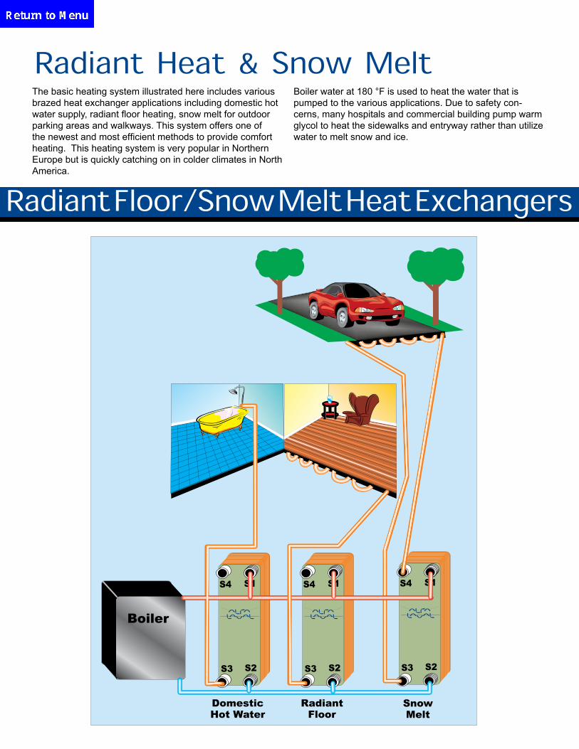
The basic heating system illustrated here includes various brazed heat exchanger applications including domestic hot water supply, radiant floor heating, snow melt for outdoor parking areas and walkways. This system offers one of the newest and most efficient methods to provide comfort heating. This heating system is very popular in Northern Europe but is quickly catching on in colder climates in North America.
Boiler water at 180 °F is used to heat the water that is pumped to the various applications. Due to safety con-cerns, many hospitals and commercial building pump warm glycol to heat the sidewalks and entryway rather than utilize water to melt snow and ice.
Radiant Heat & Snow Melt
Boiler
S4 S1
S3 S2
S4 S1
S3 S2
S4 S1
S3 S2
RadiantFloor
SnowMelt
DomesticHot Water
20000 CB14- 14H T05 3287000604 3/4" Male NPT 3/4" Male NPT 1.3 0.2 1.4 0.2 3 8.19 3.07 1.61
30000 CB14- 14H T05 3287000604 3/4" Male NPT 3/4" Male NPT 2.1 0.4 2.1 0.4 3 8.19 3.07 1.61
40000 CB14- 14H T05 3287000604 3/4" Male NPT 3/4" Male NPT 2.7 0.7 2.8 0.7 3 8.19 3.07 1.61
50000 CB14- 14H T05 3287000604 3/4" Male NPT 3/4" Male NPT 3.4 1.1 3.6 1.1 3 8.19 3.07 1.61
60000 CB14- 14H T05 3287000604 3/4" Male NPT 3/4" Male NPT 4.1 1.5 4.3 1.5 3 8.19 3.07 1.61
70000 CB14- 14H T05 3287000604 3/4" Male NPT 3/4" Male NPT 4.8 2.1 5 2 3 8.19 3.07 1.61
80000 CB14- 14H T05 3287000604 3/4" Male NPT 3/4" Male NPT 5.5 2.7 5.7 2.6 3 8.19 3.07 1.61
90000 CB14- 14H T05 3287000604 3/4" Male NPT 3/4" Male NPT 6.2 3.3 6.4 3.2 3 8.19 3.07 1.61
100000 CB14- 14H T05 3287000604 3/4" Male NPT 3/4" Male NPT 6.9 4.1 7.2 3.9 3 8.19 3.07 1.61
125000 CB14- 20H T05 3287000605 3/4" Male NPT 3/4" Male NPT 8.6 3 8.7 3 3.7 8.19 3.07 2.17
150000 CB14- 20H T05 3287000605 3/4" Male NPT 3/4" Male NPT 10.3 4.3 10.4 4.3 3.7 8.19 3.07 2.17
175000 CB14- 28H T05 3287000606 3/4" Male NPT 3/4" Male NPT 12 3.1 12.1 3.3 4.5 8.19 3.07 2.91
200000 CB14- 28H T05 3287000606 3/4" Male NPT 3/4" Male NPT 13.7 4 13.9 4.3 4.5 8.19 3.07 2.91
225000 CB27- 24H T06 3287000620 1" Male NPT 1" Male NPT 15.5 5.4 15.7 5.5 9.5 12.2 4.41 2.62
250000 CB27- 34H T06 3287000621 1" Male NPT 1" Male NPT 17.2 3.4 17.4 3.6 12.4 12.2 4.41 3.57
275000 CB27- 34H T06 3287000621 1" Male NPT 1" Male NPT 18.9 4 19.1 4.3 12.4 12.2 4.41 3.57
300000 CB27- 34H T06 3287000621 1" Male NPT 1" Male NPT 20.6 4.8 20.9 5.1 12.4 12.2 4.41 3.57
350000 CB27- 44H T06 3287000692 1" Male NPT 1" Male NPT 24 4 24.3 4.4 15.3 12.2 4.41 4.51
400000 CB27- 44H T06 3287000692 1" Male NPT 1" Male NPT 27.5 5.2 27.8 5.7 15.3 12.2 4.41 4.51
450000 CB27- 50H T06 3287000622 1" Male NPT 1" Male NPT 30.1 5.2 31 5.8 17 12.2 4.41 5.09
500000 CB27- 50H T06 3287000622 1" Male NPT 1" Male NPT 34.4 6.5 34.8 7.1 17 12.2 4.41 5.09
25000 CB14- 14H T05 3287000604 3/4" Male NPT 3/4" Male NPT 1.7 0.3 2.5 0.5 3 8.19 3.07 1.61
30000 CB14- 14H T05 3287000604 3/4" Male NPT 3/4" Male NPT 2.1 0.4 3 0.7 3 8.19 3.07 1.61
40000 CB14- 14H T05 3287000604 3/4" Male NPT 3/4" Male NPT 2.7 0.7 4 1.2 3 8.19 3.07 1.61
50000 CB14- 14H T05 3287000604 3/4" Male NPT 3/4" Male NPT 3.4 1.1 5 1.9 3 8.19 3.07 1.61
60000 CB14- 14H T05 3287000604 3/4" Male NPT 3/4" Male NPT 4.1 1.6 6 2.6 3 8.19 3.07 1.61
70000 CB14- 14H T05 3287000604 3/4" Male NPT 3/4" Male NPT 4.8 2 7 3.5 3 8.19 3.07 1.61
80000 CB14- 14H T05 3287000604 3/4" Male NPT 3/4" Male NPT 5.5 2.7 8 4.6 3 8.19 3.07 1.61
90000 CB14- 14H T05 3287000604 3/4" Male NPT 3/4" Male NPT 6.2 3.3 9 5.7 3 8.19 3.07 1.61
100000 CB14- 14H T05 3287000604 3/4" Male NPT 3/4" Male NPT 6.9 4 10 7 3 8.19 3.07 1.61
125000 CB14- 20H T05 3287000605 3/4" Male NPT 3/4" Male NPT 8.6 3 12.5 5.7 3.7 8.19 3.07 2.17
150000 CB14- 20H T05 3287000605 3/4" Male NPT 3/4" Male NPT 10.3 4.3 15 8 3.7 8.19 3.07 2.17
175000 CB14- 28H T05 3287000606 3/4" Male NPT 3/4" Male NPT 12 3.1 17.6 6.3 4.5 8.19 3.07 2.91
200000 CB14- 28H T05 3287000606 3/4" Male NPT 3/4" Male NPT 13.7 4 20 8.1 4.5 8.19 3.07 2.91
225000 CB27- 34H T06 3287000621 1" Male NPT 1" Male NPT 15.5 2.8 22.6 5.6 12.4 12.2 4.41 3.57
250000 CB27- 34H T06 3287000621 1" Male NPT 1" Male NPT 17.2 3.4 25.1 6.8 12.4 12.2 4.41 3.57
275000 CB27- 34H T06 3287000621 1" Male NPT 1" Male NPT 18.9 4.1 27.6 8.2 12.4 12.2 4.41 3.57
300000 CB27- 34H T06 3287000621 1" Male NPT 1" Male NPT 20.6 4.8 30.1 9.7 12.4 12.2 4.41 3.57
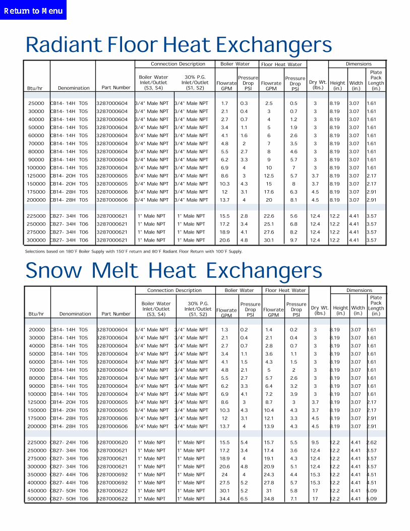
Radiant Floor Heat Exchangers
Btu/hr Denomination Part Number
Boiler Water Inlet/Outlet
(S3, S4)
30% P.G. Inlet/Outlet
(S1, S2)Flowrate
GPM
Pressure Drop PSI
Dry Wt.(lbs.)
Height (in.)
Width (in.)
Plate Pack
Length(in.)
Connection Description Bolier Water
Flowrate GPM
Pressure Drop PSI
Floor Heat Water Dimensions
Selections based on 180˚F Boiler Supply with 150˚F return and 80˚F Radiant Floor Return with 100˚F Supply.
Snow Melt Heat Exchangers
Btu/hr Denomination Part Number
Boiler Water Inlet/Outlet
(S3, S4)
30% P.G. Inlet/Outlet
(S1, S2)Flowrate
GPM
Pressure Drop PSI
Dry Wt.(lbs.)
Height (in.)
Width (in.)
Plate Pack
Length(in.)
Connection Description Bolier Water
Flowrate GPM
Pressure Drop PSI
Floor Heat Water Dimensions
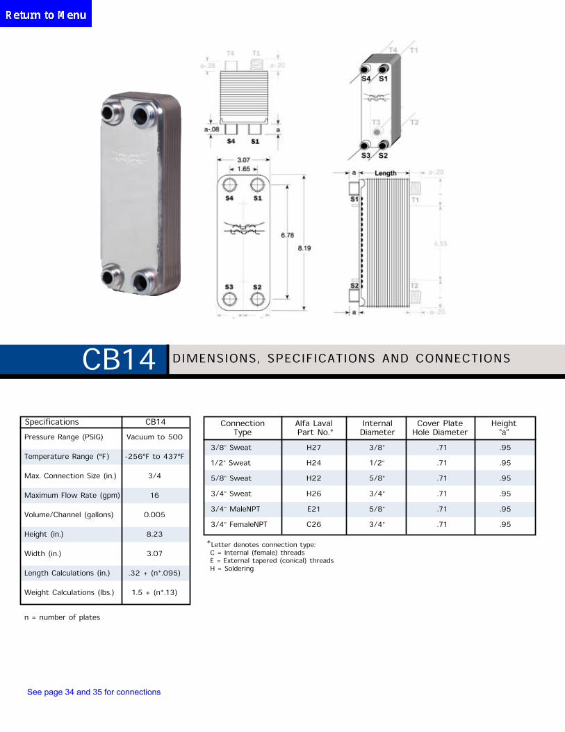
CB14 DIMENSIONS, SPECIFICATIONS AND CONNECTIONS
Pressure Range (PSIG) Vacuum to 500
Temperature Range (ºF) -256ºF to 437ºF
Max. Connection Size (in.) 3/4
Maximum Flow Rate (gpm) 16
Volume/Channel (gallons) 0.005
Height (in.) 8.23
Width (in.) 3.07
Length Calculations (in.) .32 + (n*.095)
Weight Calculations (lbs.) 1.5 + (n*.13)
Specifications CB14
n = number of plates
3/8" Sweat H27 3/8" .71 .95
1/2" Sweat H24 1/2" .71 .95
5/8" Sweat H22 5/8" .71 .95
3/4" Sweat H26 3/4" .71 .95
3/4" MaleNPT E21 5/8" .71 .95
3/4" FemaleNPT C26 3/4" .71 .95
Connection Type
Alfa Laval Part No.*
Internal Diameter
Cover PlateHole Diameter
Height“a”
* Letter denotes connection type: C = Internal (female) threads E = External tapered (conical) threads H = Soldering
See page 34 and 35 for connections
n = number of plates * Letter denotes connection type:C = Internal (female) threadsE,F = External tapered (conical) threadsH,L = SolderingR = Roto Lock: UNEF (ANSI B 1.1 - 1982)
Threaded connection with a groove suitable for an O-ring at the tightening surface.
3/8" Sweat H27 3/8" .71 .95
1/2" Sweat H24 1/2" .71 .95
5/8" Sweat H22 5/8" .71 .95
3/4" Sweat H26 3/4" .71 .95
7/8" Sweat H23 7/8" .98 .95
1-1/8" Sweat H21 1-1/8" .98 .95
1-3/8" Sweat L22 1-3/8" .98 .95
1-1/4" Roto Lock™ R21 3/4" .98 .95
3/4" MaleNPT E21 5/8" .71 .95
3/4" FemaleNPT C26 3/4" .71 .95
1" MaleNPT F21 29/32" .98 .95
Connection Type
Alfa Laval Part No.*
Internal Diameter
Cover PlateHole Diameter
Height“a”
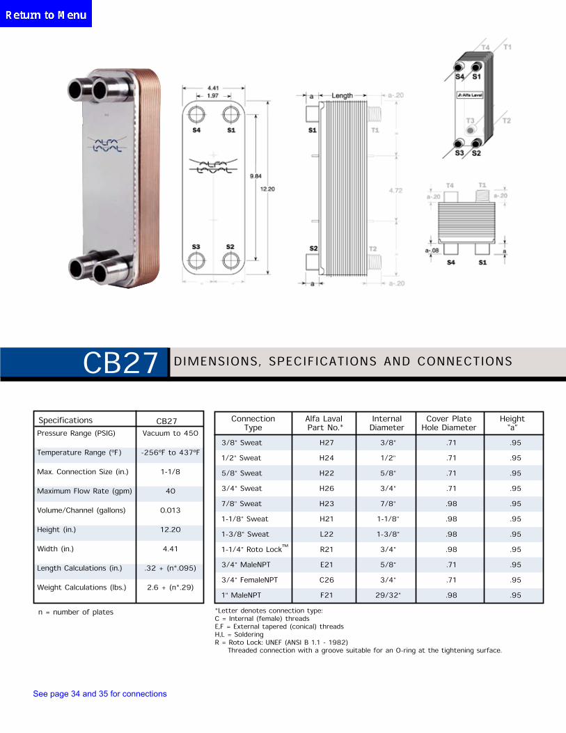
DIMENSIONS, SPECIFICATIONS AND CONNECTIONSCB27
CB27Specifications
Pressure Range (PSIG) Vacuum to 450
Temperature Range (ºF) -256ºF to 437ºF
Max. Connection Size (in.) 1-1/8
Maximum Flow Rate (gpm) 40
Volume/Channel (gallons) 0.013
Height (in.) 12.20
Width (in.) 4.41
Length Calculations (in.) .32 + (n*.095)
Weight Calculations (lbs.) 2.6 + (n*.29)
See page 34 and 35 for connections
n = number of plates
* Letter denotes connection type:C = Internal (female) threadsE,F = External tapered (conical) threadsH,L = SolderingR = Roto Lock: UNEF (ANSI B 1.1 - 1982)
Threaded connection with a groove suitable for an O-ring at the tightening surface.
Connection Type
Alfa Laval Part No.*
Internal Diameter
Cover PlateHole Diameter
Height“a”
DIMENSIONS, SPECIFICATIONS AND CONNECTIONSAC30
AC30Specifications
Pressure Rating (PSIG) Vacuum to 450
Temperature Range (°F) -319°F to 437°F
Max. Connection Size (in.) 1-1/8
Maximum Flow Rate (gpm) 40
Volume/Channel (gallons) 0.007
Height (in.) 12.8
Width (in.) 3.36
Length Calculations (in.) .35 + (n*.059)
Weight Calculations (lbs.) 2.2 + (n*.2)
1/2” Sweat H24 1/2” .71 .95
5/8” Sweat H22 5/8” .71 .95
3/4” Sweat H26 3/4” .71 .95
7/8” Sweat H23 7/8” .98 .95
1-1/8” Sweat H21 1-1/8” .98 .95
1-3/8” Sweat L22 1-3/8” .98 .95
1-3/8” Sweat H34 1-3/8 1.58 .95
1-1/4” Roto Lock™ R21 3/4” .98 .95
3/4” Male NPT E21 5/8” .71 .95
3/4” Female NPT C26 3/4” .71 .95
1” Male NPT F21 29/32” .98 .95
1-1/4” Male NPT F26 1-3/16” 1.25 1.75
See page 34 and 35 for connections
AC30
n = number of plates
1/2" Sweat H24 1/2" .71 .95
5/8" Sweat H22 5/8" .71 .95
3/4" Sweat H26 3/4" .71 .95
7/8" Sweat H23 7/8" .98 .95
1-1/8" Sweat H21 1-1/8" .98 .95
1-3/8" Sweat L22 1-3/8" .98 .95
1-3/8" Sweat H34 1-3/8" 1.58 .95
1-1/4" Roto Lock™ R21 3/4" .98 .95
3/4" MaleNPT E21 5/8" .71 .95
3/4" FemaleNPT C26 3/4" .71 .95
1" MaleNPT F21 29/32" .98 .95
1-1/4" MaleNPT F26 1-3/16" 1.25 1.75
Connection Type
Alfa Laval Part No.*
Internal Diameter
Cover PlateHole Diameter
Height“a”
* Letter denotes connection type: C = Internal (female) threads H,L = Soldering E,F = External tapered (conical) threadsR = Roto Lock: UNEF (ANSI B 1.1 - 1982) Threaded connection with a groove suitable for an O-ring at the tightening surface.
DIMENSIONS, SPECIFICATIONS AND CONNECTIONSCB52/AC50
CB52/AC50
Pressure Range (PSIG) Vacuum to 450
Temperature Range (ºF) -256ºF to 437ºF
Max. Connection Size (in.) 1-1/8
Maximum Flow Rate (gpm) 40
Volume/Channel (gallons) 0.021
Height (in.) 20.71
Width (in.) 4.41
Length Calculations (in.) .39 + (n*.094)
Weight Calculations (lbs.) 4.0 + (n*.51)
Specifications
See page 34 and 35 for connections
n = number of plates
1-1/8" Sweat D27 1-1/8" 1.5 1.18
1-3/8" Sweat D26 1-3/8" 1.5 1.18
1-5/8" Sweat H25 1-5/8" 1.5 1.18
2-1/8" Sweat D21 2-1/8" 2.0 1.58
1-3/4" Roto Lock™ R22 1-7/32" 1.5 1.18
1/2" FemaleNPT F38 1/2" 1.5 1.18
1-1/2" MaleNPT F23 1-13/32" 1.5 1.18
2" MaleNPT F22 1-15/16" 2.0 1.89
2-1/2" MaleNPT F34 2-3/8" 2.0 1.89
2" Victaulic® P23 1-15/16" 2.0 1.89
Connection Type
Alfa Laval Part No.*
Internal Diameter
Cover PlateHole Diameter
Height“a”
* Letter denotes connection type: D,H,L = Soldering F = External tapered (conical) threads P = VictaulicR = Roto Lock: UNEF (ANSI B 1.1 - 1982) Threaded connection with a groove suitable for an O-ring at the tightening surface.
DIMENSIONS, SPECIFICATIONS AND CONNECTIONSCB76
CB76
Pressure Range (PSIG) Vacuum to 435
Temperature Range (ºF) -256ºF to 437ºF
Max. Connection Size (in.) 2-1/2
Maximum Flow Rate (gpm) 150
Volume/Channel (gallons) 0.066
Height (in.) 24.29
Width (in.) 7.56
Length Calculations (in.) .39 + (n*.111)
Weight Calculations (lbs.) 16.8 + (n*.97)
Specifications
See page 34 and 35 for connections
DUAL CIRCUIT
Connection Type
Alfa Laval Part No.*
Internal Diameter
Cover PlateHole Diameter
Height“a”
1/2" Sweat H24 1/2" .71 .95
5/8" Sweat H22 5/8" .71 .95
7/8" Sweat H23 7/8" .98 .95
1-3/8" Sweat D26 1-3/8" 1.5 1.58
1-1/8" Sweat D27 1-1/8" 1.5 1.18
1-5/8" Sweat H25** 1-5/8" 1.5 1.18
3/4" FemaleNPT E36 3/4" .95 .95
1/4" FemaleNPT F36** 1/4" 0.71 .95
1/2" FemaleNPT F37** 1/2" 0.71 .95
* Letter denotes connection type: D,H = Soldering E,F = External tapered (conical) threads
**Non-standard
DIMENSIONS, SPECIFICATIONS AND CONNECTIONSAC80
n = number of plates
Pressure Range (PSIG) Vacuum to 450
Temperature Range (ºF) -256ºF to 437ºF
Max. Connection Size (in.) 1-1/8
Maximum Flow Rate (gpm) 40
Volume/Channel (gallons) 0.021
Height (in.) 20.71
Width (in.) 4.41
Length Calculations (in.) .39 + (n*.094)
Weight Calculations (lbs.) 4.0 + (n*.51)
AC80Specifications
See page 34 and 35 for connections
n = number of plates
Specifications AC120
Pressure Range (PSIG) Vacuum to 450
Temperature Range (ºF) -256ºF to 437ºF
Max. Connection Size (in.) 2-1/2
Maximum Flow Rate (gpm) 150
Volume/Channel (gallons) 0.053
Height (in.) 24.29
Width (in.) 7.56
Length Calculations (in.) .45 + (n*.094)
Weight Calculations (lbs.) 16.8 + (n*.97)
7/8" Sweat H23 7/8" .98 .95
1-1/8" Sweat H21 1-1/8" .98 .95
1-3/8" Sweat L22 1-3/8" .98 .95
1-5/8" Sweat H25 1-5/8" 1.5 1.18
2-1/8" Sweat D21 2-1/8" 2.0 1.58
1-3/4" Roto Lock™ R22 1-7/32" 1.5 1.58
1-1/2" MaleNPT F23 1-13/32" 1.5 1.18
2" MaleNPT F22 1-15/16" 2.0 1.89
2-1/2" MaleNPT F34 2-3/8" 2.0 1.89
2" Victaulic® P23 1-15/16" 2.0 1.89
Connection Type
Alfa Laval Part No.*
Internal Diameter
Cover PlateHole Diameter
Height“a”
* Letter denotes connection type: D,H,L = Soldering F = External tapered (conical) threads P = VictaulicR = Roto Lock: UNEF (ANSI B 1.1 - 1982) Threaded connection with a groove suitable for an O-ring at the tightening surface.
DIMENSIONS, SPECIFICATIONS AND CONNECTIONSAC120
DUAL CIRCUIT
See page 34 and 35 for connections
†Channels S1 & S2/Channels S3 & S4n = number of plates
* Letter denotes connection type: D,H,L = Soldering E = External tapered (conical) threads F = Internal tapered (conical) threads P = Victaulic R = Roto Lock: UNEF (ANSI B 1.1 - 1982) Threaded connection with a groove suitable for an O ring at the tightening surface.
**Non-standard
DIMENSIONS, SPECIFICATIONS AND CONNECTIONSAC130
**7/8" Sweat H23 7/8" .98 .95
1-1/8" Sweat H21** 1-1/8" .98 .95
1-3/8" Sweat L22** 1-3/8" .98 .95
1-5/8" Sweat H25** 1-5/8" 1.5 1.18
**2-1/8" Sweat D21 2-1/8" 2.0 1.58
1-3/8" Sweat D26** 1-3/8" 1.5 1.58
1-1/4" Roto Lock™ R21** 3/4" .098 .095
1-3/4" Roto Lock™ R22** 1-7/32" 1.5 1.58
1-1/4" Roto Lock™ R35** 1-9/16" 2.0 1.89
2" MaleNPT E38** 1-15/16" 2.0 1.89
2-1/2" MaleNPT E39 2-3/8" 2.0 1.89
1/2" FemaleNPT F36** 1/2" 0.71 .95
3/4" FemaleNPT F37** 3/4" 0.71 .95
2" Victaulic® P32** 1-15/16" 2.0 1.89
2-1/2" Victaulic® P31** 2-2/32" 2.16 1.89
Connection Type
Alfa Laval Part No.*
Internal Diameter
Cover PlateHole Diameter
Height“a”
Pressure Range (PSIG) Vacuum to 435/450†
Temperature Range (ºF) -256ºF to 437ºF
Max. Connection Size (in.) 2-1/2
Maximum Flow Rate (gpm) 150
Volume/Channel (gallons) 0.043
Height (in.) 19.18
Width (in.) 9.73
Length Calculations (in.) .31 + (n*.088)
Weight Calculations (lbs.) 14.3 + (n*.84)
AC130Specifications
DUAL CIRCUIT
See page 34 and 35 for connections
†Channels S1 & S2/Channels S3 & S4n = number of plates
1/2" FemaleNPT E37 1/2" .95
3/4" FemaleNPT E36 3/4" .95
1-1/8" Sweat D27 1-1/8" 1.18
1-3/8" Sweat D26 1-3/8" 1.18
2-1/8" Sweat L34 2-1/8" 2.05
2-3/8" Sweat L36 2-1/8" 2.05
2-5/8" Sweat L33 2-5/8" 2.05
3-1/8" Sweat L35 3-1/8" 2.05
2" MaleNPT F30 2" 2.05
3" MaleNPT F35 3" 2.05
2-1/2" Victaulic® P34 2-5/8" 2.05
3" Victaulic P35 3-1/16" 2.05
Connection Type
Alfa Laval Part No.*
Internal Diameter
Height“a”
* Letter denotes connection type: E = Internal (female) threads F = External tapered (conical) threads D,L = Soldering P = Victaulic
DIMENSIONS, SPECIFICATIONS AND CONNECTIONSAC250AC250Specifications
Pressure Range (PSIG) Vacuum to 362/450†
Temperature Range (ºF) -256ºF to 437ºF
Max.Connection Size (in.) 3-1/8
Maximum Flow Rate (gpm) 460
Volume/Channel (gallons) 0.100
Height (in.) 33.50
Width (in.) 12.68
Length Calculations (in.) .53 + (n*.111)
Weight Calculations (lbs.) 22.3 + (n*1.76)
See page 34 and 35 for connections
AC350Specifications
Pressure Range (PSIG) Vacuum to 362/450†
Temperature Range (ºF) -319ºF to 437ºF
Max.Connection Size (in.) 3-1/8
Maximum Flow Rate (gpm) 460
Volume/Channel (gallons) 0.106 / 1.119
Height (in.) 33
Width (in.) 12.76
Length Calculations (in.) .53 + (n*.144)
Weight Calculations (lbs.) 28.7 + (n*1.8)
†Channels S1 & S2/Channels S3 & S4n = number of plates
1/2" Female NPT E27 1/2" .95
3/4" Female NPT E26 3/4" .95
1-1/8" Sweat D27 1-1/8" 1.18
1-3/8" Sweat D26 1-3/8" 1.18
2-1/8" Sweat L34 2-1/8" 2.05
2-3/8" Sweat L36 2-3/8" 2.05
2-5/8" Sweat L33 2-5/8" 2.05
3-1/8" Sweat L35 3-1/8" 2.05
2" Male NPT F30 2" 2.05
3" Male NPT F35 3" 2.05
2-1/2" Victaulic® P34 2-5/8" 2.05
3" Victaulic P35 3-1/16" 2.05
Connection Type
Alfa Laval Part No.*
Internal Diameter
Height“a”
* Letter denotes connection type: E = Internal (female) threads F = External tapered (conical) threads D,L = Soldering P = Victaulic
DIMENSIONS, SPECIFICATIONS AND CONNECTIONSAC350
*Optional water connections on back side T1, T2. Optional Temperature Sensor Well S1, S2.
See page 34 and 35 for connections
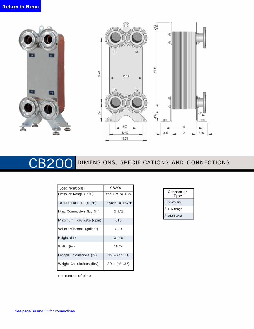
Specifications CB200
n = number of plates
Pressure Range (PSIG) Vacuum to 435
Temperature Range (ºF) -256ºF to 437ºF
Max. Connection Size (in.) 3-1/2
Maximum Flow Rate (gpm) 615
Volume/Channel (gallons) 0.13
Height (in.) 31.48
Width (in.) 15.74
Length Calculations (in.) .39 + (n*.111)
Weight Calculations (lbs.) 29 + (n*1.32)
3" Victaulic
3" DIN flange
3" ANSI weld
Connection Type
DIMENSIONS, SPECIFICATIONS AND CONNECTIONSCB200
See page 34 and 35 for connections
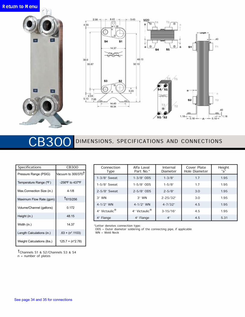
Specifications CB300
Pressure Range (PSIG) Vacuum to 300/370†
Temperature Range (ºF) -256ºF to 437ºF
Max.Connection Size (in.) 4-1/8
Maximum Flow Rate (gpm) †615/256
Volume/Channel (gallons) 0.172
Height (in.) 48.15
Width (in.) 14.37
Length Calculations (in.) .63 + (n*.1103)
Weight Calculations (lbs.) 125.7 + (n*2.78)
†Channels S1 & S2/Channels S3 & S4n = number of plates
1-3/8" Sweat 1-3/8" ODS 1-3/8" 1.7 1.95
1-5/8" Sweat 1-5/8" ODS 1-5/8" 1.7 1.95
2-5/8" Sweat 2-5/8" ODS 2-5/8" 3.0 1.95
3" WN 3" WN 2-25/32" 3.0 1.95
4-1/2" WN 4-1/2" WN 4-7/32" 4.5 1.95
4" Victaulic® 4" Victaulic® 3-15/16" 4.5 1.95
4" Flange 4" Flange 4" 4.5 5.31
Connection Type
Alfa Laval Part No.*
Internal Diameter
Cover PlateHole Diameter
Height“a”
* Letter denotes connection type: ODS = Outer diameter soldering of the connecting pipe, if applicable WN = Weld Neck
DIMENSIONS, SPECIFICATIONS AND CONNECTIONSCB300
See page 34 and 35 for connections
CombiDryers DIMENSIONS AND SPECIFICATIONS
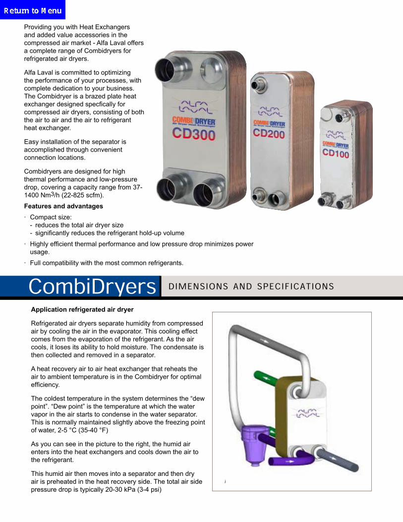
General
Providing you with Heat Exchangers and added value acces-sories in the compressed air market- Alfa Laval offers a com-plete range of Combidryers for refrigerated air dryers.
Alfa Laval is committed to optimizing the performance of yourprocesses, with complete dedication to your business. The Combidryer is a brazed plate heat exchanger designedspecifically for compressed air dryers, consisting of both theair to air and the air to refrigerant heat exchanger.
Easy installation of the separator is accomplished throughconvenient connection locations.
Combidryers are designed for high thermal performance and low-pressure drop, covering a capacity range from 37-1400 Nm3/h (22-825 scfm).
Features and advantages
• Compact size:- reduces the total air dryer size- significantly reduces the refrigerant hold-up volume
• Highly efficient thermal performance and low pressuredrop minimizes power usage.
• Full compatibility with the most common refrigerants.Application refrigerated air dryer (Figure 2)
Refrigerated air dryers separate humidity from compressed airby cooling the air in an evaporator. This cooling effect comesfrom the evaporation of the refrigerant. As the air cools, itlooses its ability to hold moisture. The condensate is then collected and removed in a separator.A heat recovery air to air heat exchanger that reheats the airto ambient temperature is in the Combidryer for optimal efficiency.
The coldest temperature in the system determines the "dewpoint". "Dew point" is the temperature at which the watervapor in the air starts to condense in the water separator.This is normally maintained slightly above the freezing point ofwater, 2-5 °C (35-40 °F).
As you can see in the picture to the right, the humid airenters into the heat exchangers and cools down in the air torefrigerant.This humid air then moves into a separator and then dry air ispreheated in the heat recovery side. The total air side pres-sure drop is typically 20-30 kPa (3-4 psi)
Figure 1. The heating surface consists of thin corrugatedstainless steel plates that are compressed together to form a plate pack. Channels are formed between the plates and the ports are
arranged so the media flows through alternate channels in fullcounter current flow. Media is directed by a brazed seal enhanced with contact points to contain the media flow pressure.
Figure 2
Providing you with Heat Exchangers and added value accessories in the compressed air market - Alfa Laval offers a complete range of Combidryers for refrigerated air dryers.
Alfa Laval is committed to optimizing the performance of your processes, with complete dedication to your business. The Combidryer is a brazed plate heat exchanger designed specfically for compressed air dryers, consisting of both the air to air and the air to refrigerant heat exchanger.
Easy installation of the separator is accomplished through convenient connection locations.
Combidryers are designed for high thermal performance and low-pressure drop, covering a capacity range from 37-1400 Nm3/h (22-825 scfm).
Application refrigerated air dryer
Refrigerated air dryers separate humidity from compressed air by cooling the air in the evaporator. This cooling effect comes from the evaporation of the refrigerant. As the air cools, it loses its ability to hold moisture. The condensate is then collected and removed in a separator.
A heat recovery air to air heat exchanger that reheats the air to ambient temperature is in the Combidryer for optimal efficiency.
The coldest temperature in the system determines the “dew point”. “Dew point” is the temperature at which the water vapor in the air starts to condense in the water separator. This is normally maintained slightly above the freezing point of water, 2-5 °C (35-40 °F)
As you can see in the picture to the right, the humid air enters into the heat exchangers and cools down the air to the refrigerant.
This humid air then moves into a separator and then dry air is preheated in the heat recovery side. The total air side pressure drop is typically 20-30 kPa (3-4 psi)
Features and advantages· Compact size: - reduces the total air dryer size - significantly reduces the refrigerant hold-up volume
· Highly efficient thermal performance and low pressure drop minimizes power usage.
· Full compatibility with the most common refrigerants.
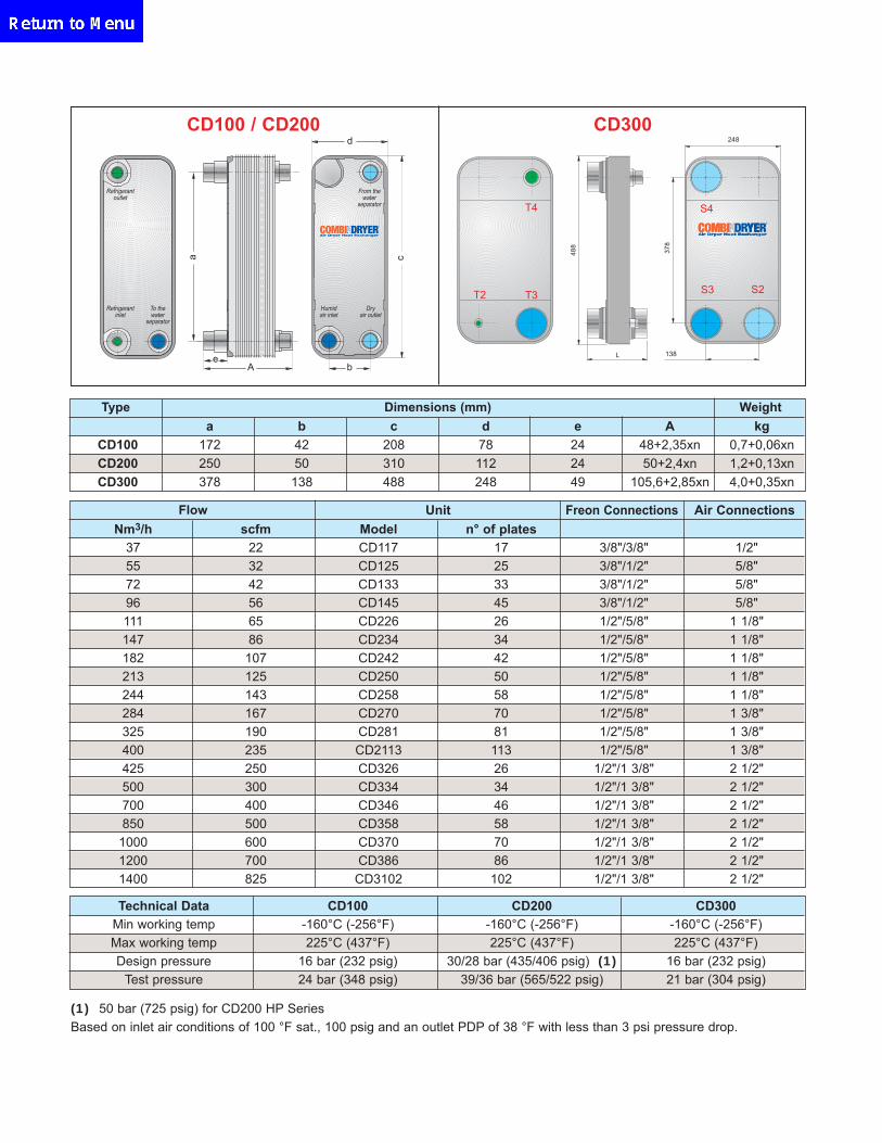
CD100 / CD200 CD300
Flow Unit Freon Connections Air ConnectionsNm3/h scfm Model n° of plates
37 22 CD117 17 3/8"/3/8" 1/2"55 32 CD125 25 3/8"/1/2" 5/8"72 42 CD133 33 3/8"/1/2" 5/8"96 56 CD145 45 3/8"/1/2" 5/8"111 65 CD226 26 1/2"/5/8" 1 1/8"147 86 CD234 34 1/2"/5/8" 1 1/8"182 107 CD242 42 1/2"/5/8" 1 1/8"213 125 CD250 50 1/2"/5/8" 1 1/8"244 143 CD258 58 1/2"/5/8" 1 1/8"284 167 CD270 70 1/2"/5/8" 1 3/8"325 190 CD281 81 1/2"/5/8" 1 3/8"400 235 CD2113 113 1/2"/5/8" 1 3/8"425 250 CD326 26 1/2"/1 3/8" 2 1/2"500 300 CD334 34 1/2"/1 3/8" 2 1/2"700 400 CD346 46 1/2"/1 3/8" 2 1/2"850 500 CD358 58 1/2"/1 3/8" 2 1/2"1000 600 CD370 70 1/2"/1 3/8" 2 1/2"1200 700 CD386 86 1/2"/1 3/8" 2 1/2"1400 825 CD3102 102 1/2"/1 3/8" 2 1/2"
a b c d e A kgCD100 172 42 208 78 24 48+2,35xn 0,7+0,06xnCD200 250 50 310 112 24 50+2,4xn 1,2+0,13xnCD300 378 138 488 248 49 105,6+2,85xn 4,0+0,35xn
138
378
248
488
T3
T4
T2
L
S4
S2S3To thewater
separator
Refrigerantoutlet
Refrigerantinlet
Humidair inlet
Dryair outlet
From thewater
separator
bAe
d
ca
Dimensions (mm) WeightType
Technical Data CD100 CD200 CD300Min working temp -160°C (-256°F) -160°C (-256°F) -160°C (-256°F)Max working temp 225°C (437°F) 225°C (437°F) 225°C (437°F)Design pressure 16 bar (232 psig) 30/28 bar (435/406 psig) (1) 16 bar (232 psig)
Test pressure 24 bar (348 psig) 39/36 bar (565/522 psig) 21 bar (304 psig)
(1) 50 bar (725 psig) for CD200 HP SeriesBased on inlet air conditions of 100 °F sat., 100 psig and an outlet PDP of 38 °F with less than 3 psi pressure drop.
* Individually packaged
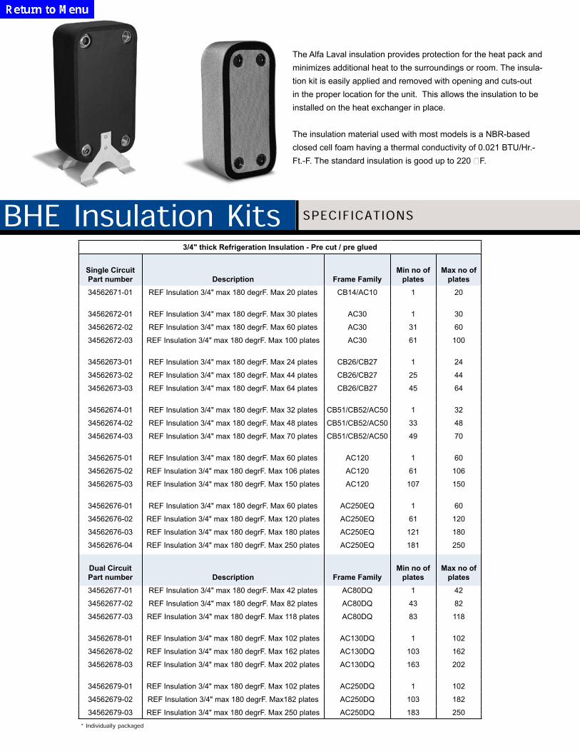
3/4" thick Refrigeration Insulation - Pre cut / pre glued
Single Circuit Part number Description Frame Family
Min no of plates
Max no of plates
34562671-01 REF Insulation 3/4" max 180 degrF. Max 20 plates CB14/AC10 1 20
34562672-01 REF Insulation 3/4" max 180 degrF. Max 30 plates AC30 1 30
34562672-02 REF Insulation 3/4" max 180 degrF. Max 60 plates AC30 31 60
34562672-03 REF Insulation 3/4" max 180 degrF. Max 100 plates AC30 61 100
34562673-01 REF Insulation 3/4" max 180 degrF. Max 24 plates CB26/CB27 1 24
34562673-02 REF Insulation 3/4" max 180 degrF. Max 44 plates CB26/CB27 25 44
34562673-03 REF Insulation 3/4" max 180 degrF. Max 64 plates CB26/CB27 45 64
34562674-01 REF Insulation 3/4" max 180 degrF. Max 32 plates CB51/CB52/AC50 1 32
34562674-02 REF Insulation 3/4" max 180 degrF. Max 48 plates CB51/CB52/AC50 33 48
34562674-03 REF Insulation 3/4" max 180 degrF. Max 70 plates CB51/CB52/AC50 49 70
34562675-01 REF Insulation 3/4" max 180 degrF. Max 60 plates AC120 1 60
34562675-02 REF Insulation 3/4" max 180 degrF. Max 106 plates AC120 61 106
34562675-03 REF Insulation 3/4" max 180 degrF. Max 150 plates AC120 107 150
34562676-01 REF Insulation 3/4" max 180 degrF. Max 60 plates AC250EQ 1 60
34562676-02 REF Insulation 3/4" max 180 degrF. Max 120 plates AC250EQ 61 120
34562676-03 REF Insulation 3/4" max 180 degrF. Max 180 plates AC250EQ 121 180
34562676-04 REF Insulation 3/4" max 180 degrF. Max 250 plates AC250EQ 181 250
Dual Circuit Part number Description Frame Family
Min no of plates
Max no of plates
34562677-01 REF Insulation 3/4" max 180 degrF. Max 42 plates AC80DQ 1 42
34562677-02 REF Insulation 3/4" max 180 degrF. Max 82 plates AC80DQ 43 82
34562677-03 REF Insulation 3/4" max 180 degrF. Max 118 plates AC80DQ 83 118
34562678-01 REF Insulation 3/4" max 180 degrF. Max 102 plates AC130DQ 1 102
34562678-02 REF Insulation 3/4" max 180 degrF. Max 162 plates AC130DQ 103 162
34562678-03 REF Insulation 3/4" max 180 degrF. Max 202 plates AC130DQ 163 202
34562679-01 REF Insulation 3/4" max 180 degrF. Max 102 plates AC250DQ 1 102
34562679-02 REF Insulation 3/4" max 180 degrF. Max182 plates AC250DQ 103 182
34562679-03 REF Insulation 3/4" max 180 degrF. Max 250 plates AC250DQ 183 250
BHE Insulation Kits SPECIFICATIONS
The Alfa Laval insulation provides protection for the heat pack and minimizes additional heat to the surroundings or room. The insula-tion kit is easily applied and removed with opening and cuts-out in the proper location for the unit. This allows the insulation to be installed on the heat exchanger in place.
The insulation material used with most models is a NBR-based closed cell foam having a thermal conductivity of 0.021 BTU/Hr.-Ft.-F. The standard insulation is good up to 220 F.
Technical Datasheet and Assembly Instruction ITEC Diffusiontight Insulation 10 or 20 mmfor Brazed Plate Heatexchanger
This insulation is made of 10 mm or 20 mm NRB-based closed cell foam and is a standard series product.
– The installation time takes about 2 minutes and it can also be applied on the already installed heatexchanger.
– Assembly instruction is also available in german:www.itec.co.at
Technical data:max. operating temperature -40°C bis +105°CHeat conductivity 0,036 W/mKHeat-transmission coefficient 1,04 W/m2KSteam diffusion resistance >7000 μFire resistance B1, Tr1, Q2
(ÖNORM B3800)
adhesive foil
closed cell foam10 or 20 mm
polyethylene 3 mm(optional)
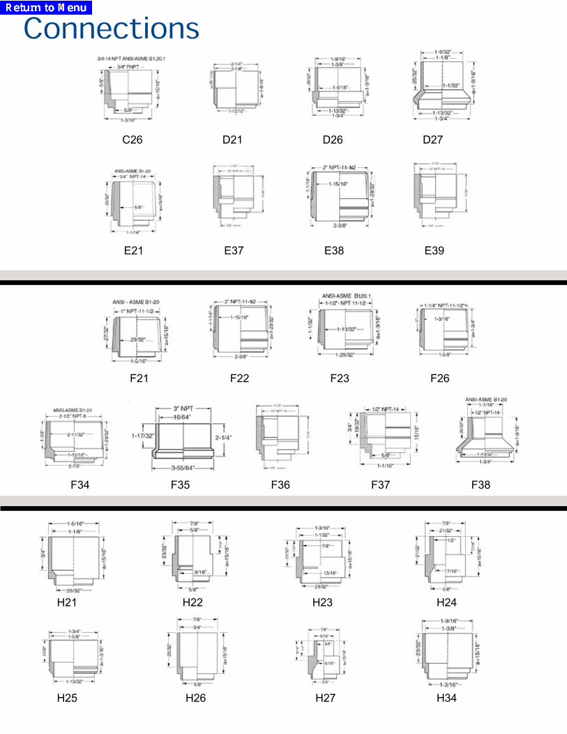
C26 D21 D26 D27
E21 E37 E38 E39
F21 F22 F23 F26
F34 F35 F36 F37 F38
Connections
H21 H22 H23 H24
H25 H26 H27 H34
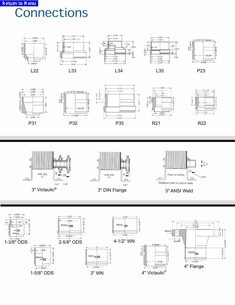
L22 L33 L34 L35 P23
P31 P32 P35 R21 R22
Connections
4" Flange4" Victaulic®
4-1/2" WN
3" WN
2-5/8" ODS
1-5/8" ODS
1-3/8" ODS
3" Victaulic® 3" DIN Flange 3" ANSI Weld


