32
Brazed Plate Heat Exchanger www.kaori-bphe.com
Brazed Plate Heat Exchanger
www.kaori-bphe.com

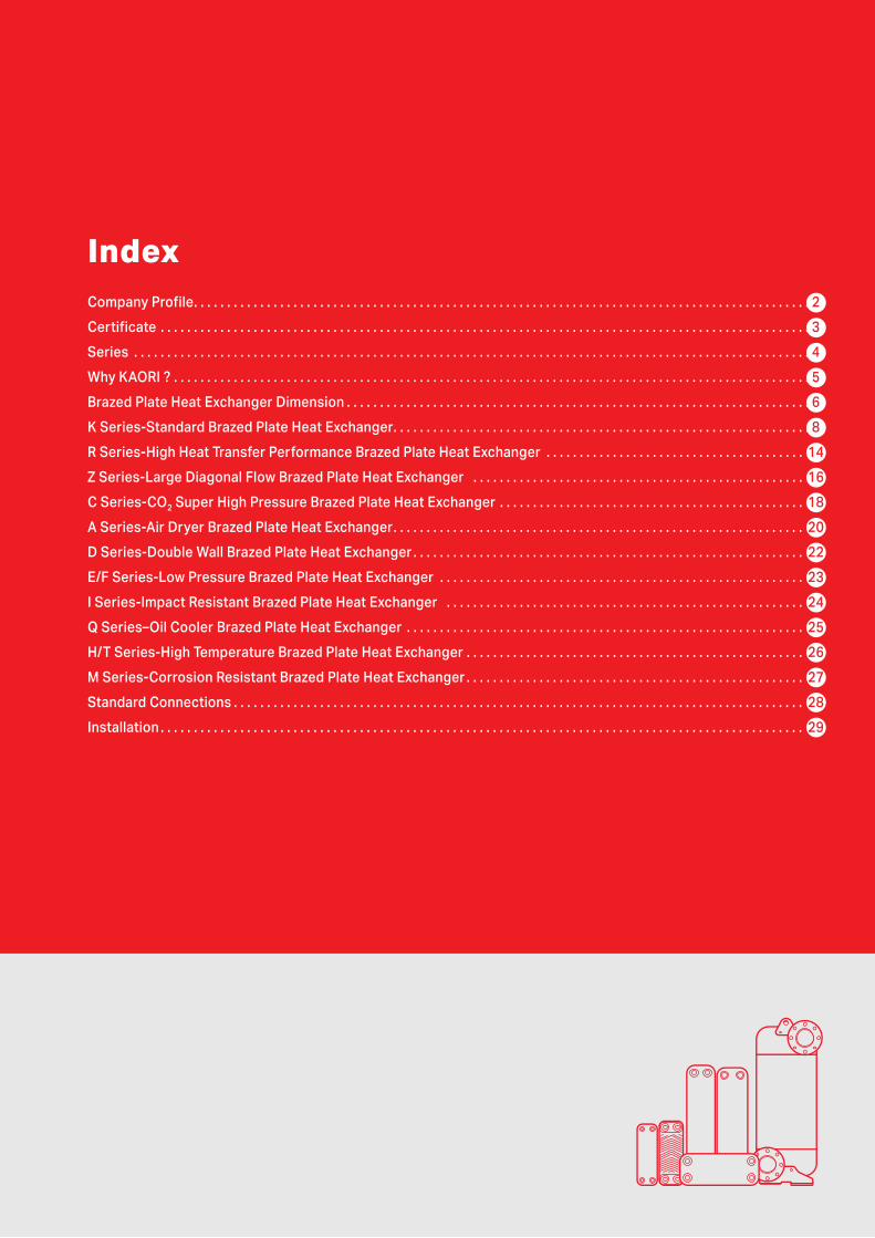
IndexCompany Profile . . . . . . . . . . . . . . . . . . . . . . . . . . . . . . . . . . . . . . . . . . . . . . . . . . . . . . . . . . . . . . . . . . . . . . . . . . . . . . . . . . . . . . . . . . . . . 2
Certificate . . . . . . . . . . . . . . . . . . . . . . . . . . . . . . . . . . . . . . . . . . . . . . . . . . . . . . . . . . . . . . . . . . . . . . . . . . . . . . . . . . . . . . . . . . . . . . . . . . 3
Series . . . . . . . . . . . . . . . . . . . . . . . . . . . . . . . . . . . . . . . . . . . . . . . . . . . . . . . . . . . . . . . . . . . . . . . . . . . . . . . . . . . . . . . . . . . . . . . . . . . . . . 4
Why KAORI ? . . . . . . . . . . . . . . . . . . . . . . . . . . . . . . . . . . . . . . . . . . . . . . . . . . . . . . . . . . . . . . . . . . . . . . . . . . . . . . . . . . . . . . . . . . . . . . . . 5
Brazed Plate Heat Exchanger Dimension . . . . . . . . . . . . . . . . . . . . . . . . . . . . . . . . . . . . . . . . . . . . . . . . . . . . . . . . . . . . . . . . . . . . . . 6
K Series-Standard Brazed Plate Heat Exchanger . . . . . . . . . . . . . . . . . . . . . . . . . . . . . . . . . . . . . . . . . . . . . . . . . . . . . . . . . . . . . . . 8
R Series-High Heat Transfer Performance Brazed Plate Heat Exchanger . . . . . . . . . . . . . . . . . . . . . . . . . . . . . . . . . . . . . . . 14
Z Series-Large Diagonal Flow Brazed Plate Heat Exchanger . . . . . . . . . . . . . . . . . . . . . . . . . . . . . . . . . . . . . . . . . . . . . . . . . . 16
C Series-CO2 Super High Pressure Brazed Plate Heat Exchanger . . . . . . . . . . . . . . . . . . . . . . . . . . . . . . . . . . . . . . . . . . . . . . 18
A Series-Air Dryer Brazed Plate Heat Exchanger . . . . . . . . . . . . . . . . . . . . . . . . . . . . . . . . . . . . . . . . . . . . . . . . . . . . . . . . . . . . . . 20
D Series-Double Wall Brazed Plate Heat Exchanger . . . . . . . . . . . . . . . . . . . . . . . . . . . . . . . . . . . . . . . . . . . . . . . . . . . . . . . . . . . 22
E/F Series-Low Pressure Brazed Plate Heat Exchanger . . . . . . . . . . . . . . . . . . . . . . . . . . . . . . . . . . . . . . . . . . . . . . . . . . . . . . . 23
I Series-Impact Resistant Brazed Plate Heat Exchanger . . . . . . . . . . . . . . . . . . . . . . . . . . . . . . . . . . . . . . . . . . . . . . . . . . . . . . 24
Q Series–Oil Cooler Brazed Plate Heat Exchanger . . . . . . . . . . . . . . . . . . . . . . . . . . . . . . . . . . . . . . . . . . . . . . . . . . . . . . . . . . . . 25
H/T Series-High Temperature Brazed Plate Heat Exchanger . . . . . . . . . . . . . . . . . . . . . . . . . . . . . . . . . . . . . . . . . . . . . . . . . . . 26
M Series-Corrosion Resistant Brazed Plate Heat Exchanger . . . . . . . . . . . . . . . . . . . . . . . . . . . . . . . . . . . . . . . . . . . . . . . . . . . 27
Standard Connections . . . . . . . . . . . . . . . . . . . . . . . . . . . . . . . . . . . . . . . . . . . . . . . . . . . . . . . . . . . . . . . . . . . . . . . . . . . . . . . . . . . . . . 28
Installation . . . . . . . . . . . . . . . . . . . . . . . . . . . . . . . . . . . . . . . . . . . . . . . . . . . . . . . . . . . . . . . . . . . . . . . . . . . . . . . . . . . . . . . . . . . . . . . . . 29

KAORI was established in 1970, insisting on pursuing innovative technology and manufacturing
world-class products as its main goal. Consistently improving, researching, and importing new
technology, KAORI launched the brazed plate heat exchanger division in 1994, and the quality
system was ISO9001 certified in 1995; afterward KAORI brazed plate heat exchanger obtained
numerous patents and certificates. In order to fulfill the increasing demand from the worldwide
market, Kaohsiung plant and Ningbo plant were built in 2002 and 2005 to provide larger
production capacity. KAORI brazed plate heat exchanger is the No.1 brand in Taiwan and has
been exported to more than 50 countries.
Chung-Li Taiwan Plant Kaohsiung Taiwan Plant Ningbo China Plant
Facility and Test Equipment
Vacuum Furnace
CO2 High Pressure Test
Performance Test
Continuous Pressing
Helium Leakage Test
Pressure Leakage Test
Salt Spray Test
Thermal Shock Tester
Burst Test
Company Profile
KAORI Brazed Plate Heat Exchanger Plants
2

Certificate
Patent
CO2 High Pressure BPHE Patents in Taiwan, China, Japan and Germany
Air Dryer BPHE Patents in Taiwan, Japan, Korea, and USA Double Wall BPHE Patents in Taiwan, Germany and China
ASME
CE/PED JAPAN KHK
UL CRN
ISO9001:2015
3
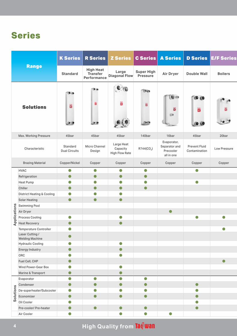
Series
Range
K Series R Series Z Series C Series A Series D Series E/F Series I Series Q Series H/T Series M Series
Standard High Heat Transfer
Performance
Large Diagonal Flow
Super High Pressure Air Dryer Double Wall Boilers Impact
Resistance Oil Cooler Fuel Cell Corrosion Resistance
Solutions
Max. Working Pressure 45bar 45bar 45bar 140bar 16bar 45bar 20bar 30bar 30bar 10bar 10bar
CharacteristicStandard
Dual Circuits Micro Channel
Design
Large Heat Capacity
High Flow RateR744(CO2)
Evaporator, Separator and
Precooler all in one
Prevent Fluid Contamination
Low PressurePressure and
Thermal Shock Endurable
Shell & TubeReplacement
High TemperatureCorrosion Resistant Material
Brazing Material Copper/Nickel Copper Copper Copper Copper Copper Copper Copper Copper Nickel Nickel
HVAC ● ● ● ● ●Refrigeration ● ● ● ●Heat Pump ● ● ● ● ●Chiller ● ● ● ●District Heating & Cooling ● ● ●Solar Heating ● ● ●Swimming Pool ●Air Dryer ●Process Cooling ● ● ● ● ●Heat Recovery ● ● ●Temperature Controller ● ●Laser Cutting / Welding Machine
●
Hydraulic Cooling ● ● ● ●Energy Industry ● ●ORC ● ●Fuel Cell, CHP ● ● ●Wind Power-Gear Box ● ●Marine & Transport ● ● ●Evaporator ● ● ● ●Condenser ● ● ● ● ●De-superheater/Subcooler ● ● ● ● ●Economizer ● ● ● ● ● ●Oil Cooler ● ● ● ●Pre-cooler/ Pre-heater ● ● ● ● ●Air Cooler ● ● ● ● ● ●
Ap
plic
atio
ns
So
luti
on
s
Range
4
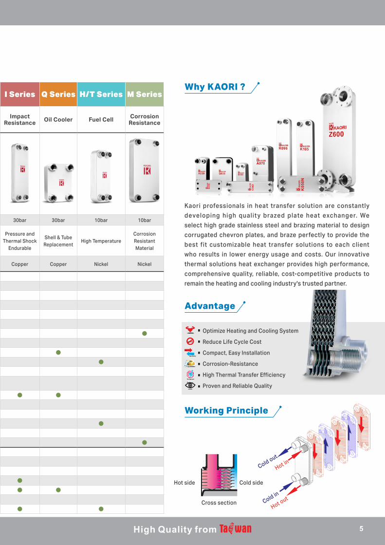
Kaori professionals in heat transfer solution are constantly
developing high qualit y brazed plate heat exchanger. We
select high grade stainless steel and brazing material to design
corrugated chevron plates, and braze perfectly to provide the
best fit customizable heat transfer solutions to each client
who results in lower energy usage and costs. Our innovative
thermal solutions heat exchanger provides high performance,
comprehensive quality, reliable, cost-competitive products to
remain the heating and cooling industry's trusted partner.
Cold side
Range
K Series R Series Z Series C Series A Series D Series E/F Series I Series Q Series H/T Series M Series
Standard High Heat Transfer
Performance
Large Diagonal Flow
Super High Pressure Air Dryer Double Wall Boilers Impact
Resistance Oil Cooler Fuel Cell Corrosion Resistance
Solutions
Max. Working Pressure 45bar 45bar 45bar 140bar 16bar 45bar 20bar 30bar 30bar 10bar 10bar
CharacteristicStandard
Dual Circuits Micro Channel
Design
Large Heat Capacity
High Flow RateR744(CO2)
Evaporator, Separator and
Precooler all in one
Prevent Fluid Contamination
Low PressurePressure and
Thermal Shock Endurable
Shell & TubeReplacement
High TemperatureCorrosion Resistant Material
Brazing Material Copper/Nickel Copper Copper Copper Copper Copper Copper Copper Copper Nickel Nickel
HVAC ● ● ● ● ●Refrigeration ● ● ● ●Heat Pump ● ● ● ● ●Chiller ● ● ● ●District Heating & Cooling ● ● ●Solar Heating ● ● ●Swimming Pool ●Air Dryer ●Process Cooling ● ● ● ● ●Heat Recovery ● ● ●Temperature Controller ● ●Laser Cutting / Welding Machine
●
Hydraulic Cooling ● ● ● ●Energy Industry ● ●ORC ● ●Fuel Cell, CHP ● ● ●Wind Power-Gear Box ● ●Marine & Transport ● ● ●Evaporator ● ● ● ●Condenser ● ● ● ● ●De-superheater/Subcooler ● ● ● ● ●Economizer ● ● ● ● ● ●Oil Cooler ● ● ● ●Pre-cooler/ Pre-heater ● ● ● ● ●Air Cooler ● ● ● ● ● ●
Advantage
Working Principle
Why KAORI ?
Long
life time
durabilityLong
life time
durability
CorrosionCorrosion
High efficiency
Hot
High efficiency
Hot
Cold
Easy InstallationEasy Installation
Tesl ApprovedTesl Approved
monito r
Flow&tem p
monito r
Flow&tem p
Optimize Heating and Cooling System
Reduce Life Cycle Cost
Compact, Easy Installation
Corrosion-Resistance
High Thermal Transfer Efficiency
Proven and Reliable Quality
Hot side
Cross sectionHot outCold in
Cold out
Hot in
5
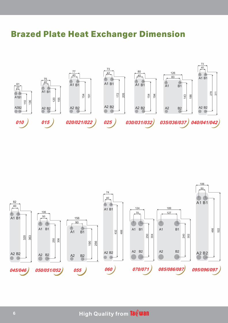
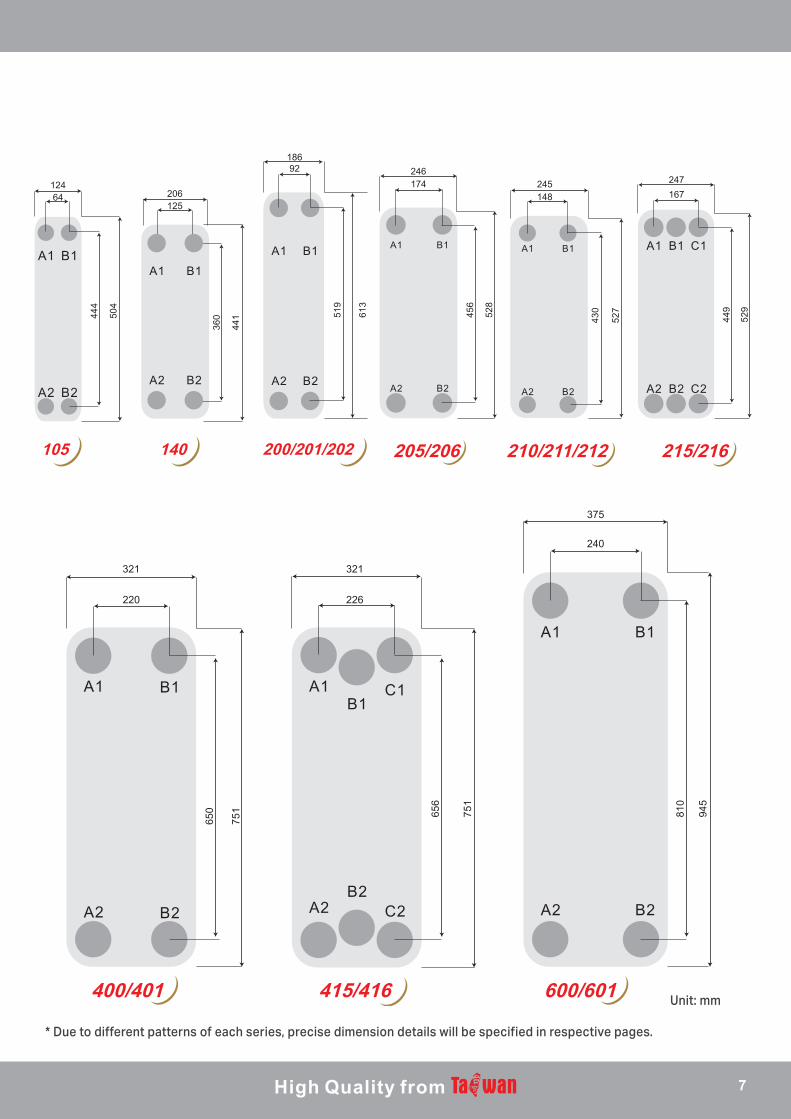
Brazed Plate Heat Exchanger Dimension
6127
7540
7740
7342 80
4012683
110
136 12
0
155 15
4
191
172
205
154
194
143
186
7340
278
311
010 015 020/021/022 025 030/031/032 035/036/037 040/041/042
106
50
40
74
70
124
50
106
8240
320
363
250
306 25
0
304
466
522
432
466
15690
190
256
050/051/052 055045/046 060 070/071
127
189
240
302
085/086/087 095/096/097
6
64124
125206
444
504
360
441
18692 246
174 245148
247167
519
613
456
528
430
527
449
529
105 140 200/201/202 205/206 210/211/212 215/216
321 321
220 226
375
240
650
751 65
6
751
810
945
400/401 415/416 600/601
* Due to different patterns of each series, precise dimension details will be specified in respective pages.
Unit: mm
7
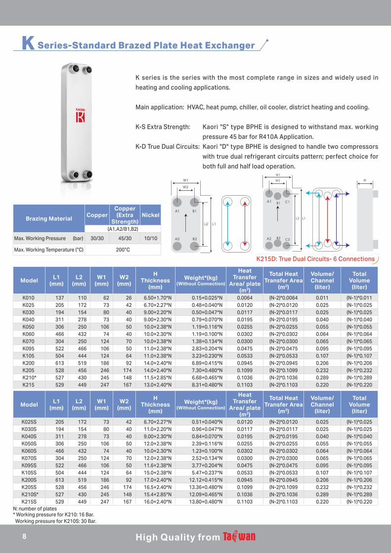
K Series-Standard Brazed Plate Heat Exchanger
K series is the series with the most complete range in sizes and widely used in
heating and cooling applications.
Main application: HVAC, heat pump, chiller, oil cooler, district heating and cooling.
K-S Extra Strength: Kaori "S" type BPHE is designed to withstand max. working
pressure 45 bar for R410A Application.
K-D True Dual Circuits: Kaori "D" type BPHE is designed to handle two compressors
with true dual refrigerant circuits pattern; perfect choice for
both full and half load operation.
Brazing MaterialCopper
Copper (Extra
Strength)Nickel
(A1,A2/B1,B2)
Max. Working Pressure (bar) 30/30 45/30 10/10
Max. Working Temperature (°C) 200°C
Model L1(mm)
L2(mm)
W1(mm)
W2(mm)
HThickness
(mm)
Weight*(kg)(Without Connection)
Heat Transfer
Area/ plate (m2)
Total Heat Transfer Area
(m2)
Volume/ Channel
(liter)
Total Volume
(liter)
K010 137 110 62 26 6.50+1.70*N 0.15+0.025*N 0.0064 (N-2)*0.0064 0.011 (N-1)*0.011K025 205 172 73 42 6.70+2.27*N 0.48+0.040*N 0.0120 (N-2)*0.0120 0.025 (N-1)*0.025K030 194 154 80 40 9.00+2.20*N 0.50+0.047*N 0.0117 (N-2)*0.0117 0.025 (N-1)*0.025K040 311 278 73 40 9.00+2.30*N 0.79+0.070*N 0.0195 (N-2)*0.0195 0.040 (N-1)*0.040K050 306 250 106 50 10.0+2.38*N 1.19+0.116*N 0.0255 (N-2)*0.0255 0.055 (N-1)*0.055K060 466 432 74 40 10.0+2.30*N 1.19+0.100*N 0.0302 (N-2)*0.0302 0.064 (N-1)*0.064K070 304 250 124 70 10.0+2.38*N 1.38+0.134*N 0.0300 (N-2)*0.0300 0.065 (N-1)*0.065K095 522 466 106 50 11.0+2.38*N 2.83+0.204*N 0.0475 (N-2)*0.0475 0.095 (N-1)*0.095K105 504 444 124 64 11.0+2.38*N 3.23+0.230*N 0.0533 (N-2)*0.0533 0.107 (N-1)*0.107K200 613 519 186 92 14.0+2.40*N 6.89+0.415*N 0.0945 (N-2)*0.0945 0.206 (N-1)*0.206K205 528 456 246 174 14.0+2.40*N 7.30+0.480*N 0.1099 (N-2)*0.1099 0.232 (N-1)*0.232K210* 527 430 245 148 11.5+2.85*N 6.68+0.465*N 0.1036 (N-2)*0.1036 0.289 (N-1)*0.289K215 529 449 247 167 13.0+2.40*N 8.31+0.480*N 0.1103 (N-2)*0.1103 0.220 (N-1)*0.220
Model L1(mm)
L2(mm)
W1(mm)
W2(mm)
HThickness
(mm)
Weight*(kg)(Without Connection)
Heat Transfer
Area/ plate (m2)
Total Heat Transfer Area
(m2)
Volume/ Channel
(liter)
Total Volume
(liter)
K025S 205 172 73 42 6.70+2.27*N 0.51+0.040*N 0.0120 (N-2)*0.0120 0.025 (N-1)*0.025K030S 194 154 80 40 11.0+2.20*N 0.96+0.047*N 0.0117 (N-2)*0.0117 0.025 (N-1)*0.025K040S 311 278 73 40 9.00+2.30*N 0.84+0.070*N 0.0195 (N-2)*0.0195 0.040 (N-1)*0.040K050S 306 250 106 50 12.0+2.38*N 2.39+0.116*N 0.0255 (N-2)*0.0255 0.055 (N-1)*0.055K060S 466 432 74 40 10.0+2.30*N 1.23+0.100*N 0.0302 (N-2)*0.0302 0.064 (N-1)*0.064K070S 304 250 124 70 12.0+2.38*N 2.52+0.134*N 0.0300 (N-2)*0.0300 0.065 (N-1)*0.065K095S 522 466 106 50 11.6+2.38*N 3.77+0.204*N 0.0475 (N-2)*0.0475 0.095 (N-1)*0.095K105S 504 444 124 64 15.0+2.38*N 5.47+0.237*N 0.0533 (N-2)*0.0533 0.107 (N-1)*0.107K200S 613 519 186 92 17.0+2.40*N 12.12+0.415*N 0.0945 (N-2)*0.0945 0.206 (N-1)*0.206K205S 528 456 246 174 16.5+2.40*N 13.36+0.480*N 0.1099 (N-2)*0.1099 0.232 (N-1)*0.232K210S* 527 430 245 148 15.4+2.85*N 12.09+0.465*N 0.1036 (N-2)*0.1036 0.289 (N-1)*0.289K215S 529 449 247 167 16.0+2.40*N 13.80+0.480*N 0.1103 (N-2)*0.1103 0.220 (N-1)*0.220
B1 C1
B2 C2
K215D: True Dual Circuits- 6 Connections
N: number of plates* Working pressure for K210: 16 Bar. Working pressure for K210S: 30 Bar.
8
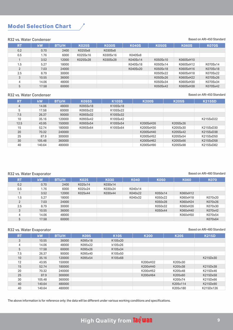
R32 vs. Water Condenser
R32 vs. Water Evaporator
R32 vs. Water Condenser
R32 vs. Water Evaporator
Based on ARI-450 Standard
Based on ARI-480 Standard
Based on ARI-450 Standard
Based on ARI-480 Standard
The above information is for reference only; the data will be different under various working conditions and specifications.
Model Selection Chart
RT kW BTU/H K025 K030 K040 K050 K060 K0700.2 0.70 2400 K025x14 K030x140.5 1.76 6000 K025x24 K030x24 K040x141 3.52 12000 K025x44 K030x44 K040x22 K050x14 K060xH12
1.5 5.27 18000 K040x32 K050x22 K060xH18 K070x202 7.03 24000 K050x28 K060xH24 K070x26
2.5 8.79 30000 K050x32 K060xH26 K070x303 10.55 36000 K050x44 K060xH40 K070x424 14.06 48000 K060xH50 K070x545 17.58 60000 K070x64
RT kW BTU/H K095 K105 K200 K205 K215D3 10.55 36000 K095x18 K105x204 14.06 48000 K095x22 k105x265 17.58 60000 K095x26 K105x34
7.5 26.37 90000 K095x40 K105x5010 35.16 120000 K095x54 K105x68 K215Dx3012 43.95 150000 K200xH32 K205x3015 52.74 180000 K200xH40 K205x38 K215Dx3820 70.32 240000 K200xH52 K205x48 K215Dx4625 87.9 300000 K200xH64 K205x60 K215Dx5830 105.48 360000 K205x74 K215Dx6640 140.64 480000 K205x114 K215Dx9040 140.64 480000 K205x180 K215Dx126
RT kW BTU/H K025S K030S K040S K050S K060S K070S0.2 0.70 2400 K025Sx8 K030Sx80.5 1.76 6000 K025Sx16 K030Sx16 K040Sx81 3.52 12000 K025Sx28 K030Sx28 K040Sx14 K050Sx10 K060SxH10
1.5 5.27 18000 K040Sx18 K050Sx14 K060SxH12 K070Sx142 7.03 24000 K040Sx20 K050Sx18 K060SxH16 K070Sx18
2.5 8.79 30000 K050Sx22 K060SxH18 K070Sx223 10.55 36000 K050Sx26 K060SxH22 K070Sx264 14.06 48000 K050Sx34 K060SxH30 K070Sx345 17.58 60000 K050Sx42 K060SxH38 K070Sx42
RT kW BTU/H K095S K105S K200S K205S K215SD4 14.06 48000 K095Sx18 K105Sx185 17.58 60000 K095Sx22 K105Sx22
7.5 26.37 90000 K095Sx32 K105Sx3210 35.16 120000 K095Sx42 K105Sx42 K215SxD22
12.5 43.95 150000 K095Sx54 K105Sx54 K200SxH26 K205Sx2615 52.74 180000 K095Sx64 K105Sx64 K200SxH30 K205Sx30 K215SxD3020 70.32 240000 K200SxH40 K205Sx42 K215SxD3825 87.9 300000 K200SxH52 K205Sx54 K215SxD5030 105.48 360000 K200SxH62 K205Sx66 K215SxD5840 140.64 480000 K200SxH90 K205Sx98 K215SxD82
9
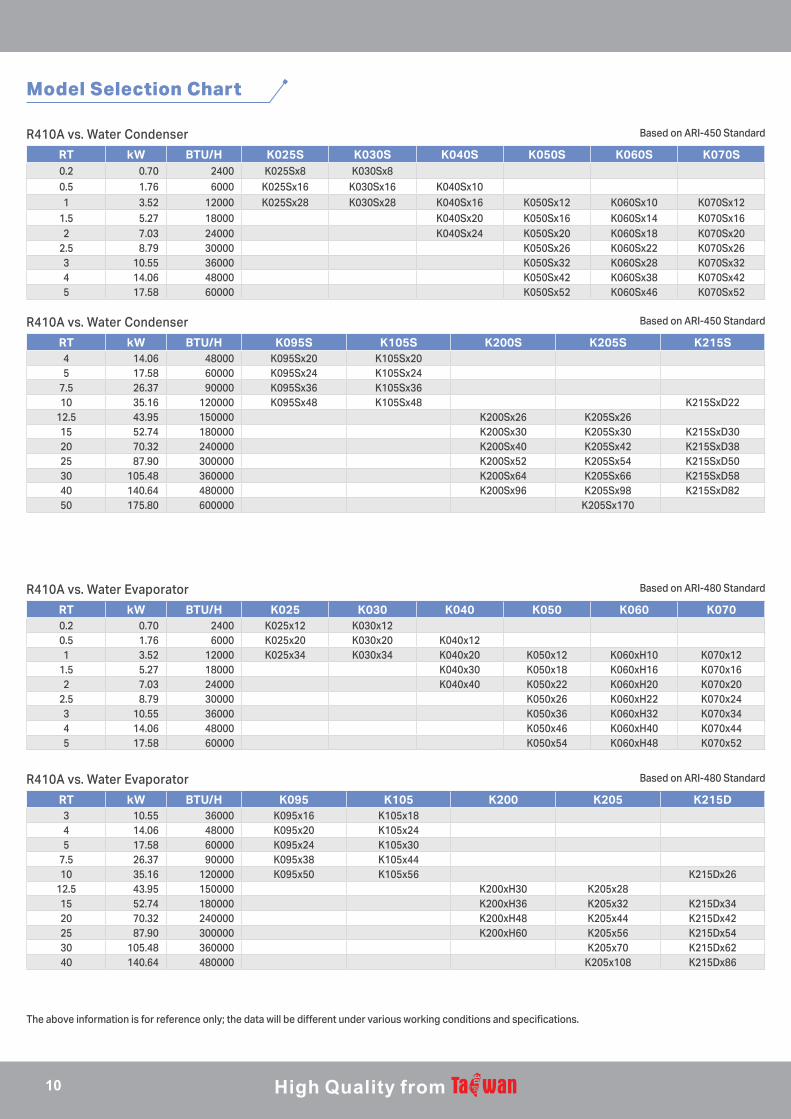
RT kW BTU/H K025S K030S K040S K050S K060S K070S0.2 0.70 2400 K025Sx8 K030Sx80.5 1.76 6000 K025Sx16 K030Sx16 K040Sx101 3.52 12000 K025Sx28 K030Sx28 K040Sx16 K050Sx12 K060Sx10 K070Sx12
1.5 5.27 18000 K040Sx20 K050Sx16 K060Sx14 K070Sx162 7.03 24000 K040Sx24 K050Sx20 K060Sx18 K070Sx20
2.5 8.79 30000 K050Sx26 K060Sx22 K070Sx263 10.55 36000 K050Sx32 K060Sx28 K070Sx324 14.06 48000 K050Sx42 K060Sx38 K070Sx425 17.58 60000 K050Sx52 K060Sx46 K070Sx52
RT kW BTU/H K025 K030 K040 K050 K060 K0700.2 0.70 2400 K025x12 K030x120.5 1.76 6000 K025x20 K030x20 K040x121 3.52 12000 K025x34 K030x34 K040x20 K050x12 K060xH10 K070x12
1.5 5.27 18000 K040x30 K050x18 K060xH16 K070x162 7.03 24000 K040x40 K050x22 K060xH20 K070x20
2.5 8.79 30000 K050x26 K060xH22 K070x243 10.55 36000 K050x36 K060xH32 K070x344 14.06 48000 K050x46 K060xH40 K070x445 17.58 60000 K050x54 K060xH48 K070x52
RT kW BTU/H K095S K105S K200S K205S K215S4 14.06 48000 K095Sx20 K105Sx205 17.58 60000 K095Sx24 K105Sx24
7.5 26.37 90000 K095Sx36 K105Sx3610 35.16 120000 K095Sx48 K105Sx48 K215SxD22
12.5 43.95 150000 K200Sx26 K205Sx2615 52.74 180000 K200Sx30 K205Sx30 K215SxD3020 70.32 240000 K200Sx40 K205Sx42 K215SxD3825 87.90 300000 K200Sx52 K205Sx54 K215SxD5030 105.48 360000 K200Sx64 K205Sx66 K215SxD5840 140.64 480000 K200Sx96 K205Sx98 K215SxD8250 175.80 600000 K205Sx170
RT kW BTU/H K095 K105 K200 K205 K215D3 10.55 36000 K095x16 K105x184 14.06 48000 K095x20 K105x245 17.58 60000 K095x24 K105x30
7.5 26.37 90000 K095x38 K105x4410 35.16 120000 K095x50 K105x56 K215Dx26
12.5 43.95 150000 K200xH30 K205x2815 52.74 180000 K200xH36 K205x32 K215Dx3420 70.32 240000 K200xH48 K205x44 K215Dx4225 87.90 300000 K200xH60 K205x56 K215Dx5430 105.48 360000 K205x70 K215Dx6240 140.64 480000 K205x108 K215Dx86
Model Selection Chart
R410A vs. Water Condenser
R410A vs. Water Evaporator
R410A vs. Water Condenser
R410A vs. Water Evaporator
Based on ARI-450 Standard
Based on ARI-480 Standard
Based on ARI-450 Standard
Based on ARI-480 Standard
The above information is for reference only; the data will be different under various working conditions and specifications.
10

R134a vs. Water Condenser
R134a vs. Water Evaporator
R134a vs. Water Condenser
R134a vs. Water Evaporator
Based on ARI-450 Standard
Based on ARI-480 Standard
Based on ARI-450 Standard
Based on ARI-480 Standard
The above information is for reference only; the data will be different under various working conditions and specifications.
Model Selection Chart
RT kW BTU/H K025 K030 K040 K050 K060 K0700.2 0.70 2400 K025x8 K030x80.5 1.76 6000 K025x16 K030x16 K040x101 3.52 12000 K025x30 K030x30 K040x18 K050x16 K060xH14 K070x16
1.5 5.27 18000 K040x24 K050x22 K060xH20 K070x222 7.03 24000 K040x32 K050x28 K060xH24 K070x26
2.5 8.79 30000 K050x34 K060xH30 K070x323 10.55 36000 K050x42 K060xH38 K070x404 14.06 48000 K050x56 K060xH50 K070x545 17.58 60000 K050x68 K060xH60 K070x66
RT kW BTU/H K025 K030 K040 K050 K060 K0700.2 0.70 2400 K025x12 K030x120.5 1.76 6000 K025x20 K030x20 K040x121 3.52 12000 K025x36 K030x36 K040x20 K050x14 K060xM14 K070x14
1.5 5.27 18000 K040x32 K050x18 K060xM18 K070x182 7.03 24000 K040x40 K050x22 K060xM22 K070x20
2.5 8.79 30000 K050x28 K060xM28 K070x263 10.55 36000 K050x36 K060xM36 K070x344 14.06 48000 K050x44 K060xM44 K070x425 17.58 60000 K050x56 K060xM56 K070x54
RT kW BTU/H K095 K105 K200 K205 K215D3 10.55 36000 K095x18 K105x184 14.06 48000 K095x24 K105x245 17.58 60000 K095x28 K105x28
7.5 26.37 90000 K095x42 K105x4210 35.16 120000 K095x56 K105x56 K200xH30 K205x20 K215Dx18
12.5 43.95 150000 K200xH38 K205x2615 52.74 180000 K200xH46 K205x30 K215Dx3020 70.32 240000 K200xH60 K205x42 K215Dx3825 87.90 300000 K200xH76 K205x54 K215Dx5030 105.48 360000 K200xH90 K205x66 K215Dx5840 140.64 480000 K200xH120 K205x98 K215Dx8250 175.80 600000 K205x138
RT kW BTU/H K095 K105 K200 K205 K215D2.5 8.79 30000 K095x16 K105x203 10.55 36000 K095x20 K105x244 14.06 48000 K095x24 K105x305 17.58 60000 K095x30 K105x36
7.5 26.37 90000 K095x46 K105x5410 35.16 120000 K095x64 K105x84 K200xH32 K205x32 K215Dx34
12.5 43.95 150000 K200xH38 K205x4015 52.74 180000 K200xH46 K205x48 K215Dx4620 70.32 240000 K200xH60 K205x64 K215Dx6225 87.90 300000 K205x84 K215Dx7830 105.48 360000 K205x108 K215Dx9440 140.64 480000 K205x180 K215Dx126
11
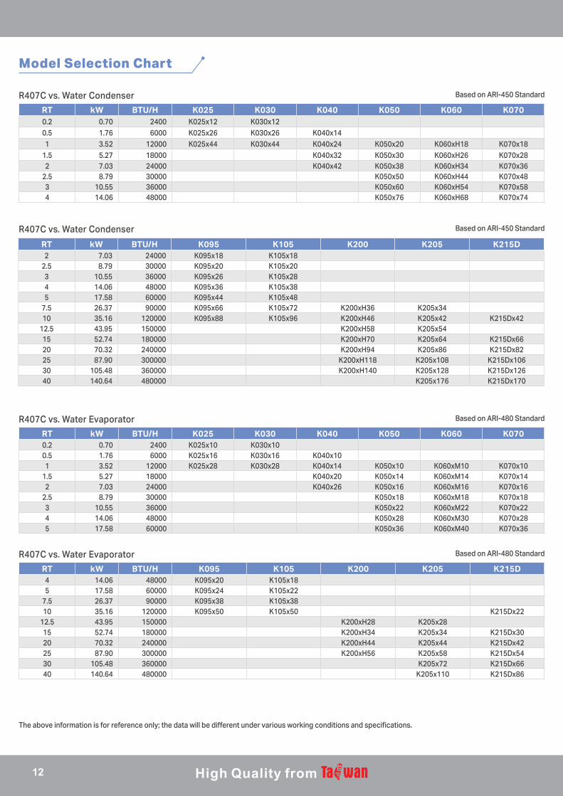
R407C vs. Water Condenser
R407C vs. Water Evaporator
R407C vs. Water Condenser
R407C vs. Water Evaporator
Based on ARI-450 Standard
Based on ARI-480 Standard
Based on ARI-450 Standard
Based on ARI-480 Standard
The above information is for reference only; the data will be different under various working conditions and specifications.
Model Selection Chart
RT kW BTU/H K025 K030 K040 K050 K060 K0700.2 0.70 2400 K025x12 K030x120.5 1.76 6000 K025x26 K030x26 K040x141 3.52 12000 K025x44 K030x44 K040x24 K050x20 K060xH18 K070x18
1.5 5.27 18000 K040x32 K050x30 K060xH26 K070x282 7.03 24000 K040x42 K050x38 K060xH34 K070x36
2.5 8.79 30000 K050x50 K060xH44 K070x483 10.55 36000 K050x60 K060xH54 K070x584 14.06 48000 K050x76 K060xH68 K070x74
RT kW BTU/H K025 K030 K040 K050 K060 K0700.2 0.70 2400 K025x10 K030x100.5 1.76 6000 K025x16 K030x16 K040x101 3.52 12000 K025x28 K030x28 K040x14 K050x10 K060xM10 K070x10
1.5 5.27 18000 K040x20 K050x14 K060xM14 K070x142 7.03 24000 K040x26 K050x16 K060xM16 K070x16
2.5 8.79 30000 K050x18 K060xM18 K070x183 10.55 36000 K050x22 K060xM22 K070x224 14.06 48000 K050x28 K060xM30 K070x285 17.58 60000 K050x36 K060xM40 K070x36
RT kW BTU/H K095 K105 K200 K205 K215D2 7.03 24000 K095x18 K105x18
2.5 8.79 30000 K095x20 K105x203 10.55 36000 K095x26 K105x284 14.06 48000 K095x36 K105x385 17.58 60000 K095x44 K105x48
7.5 26.37 90000 K095x66 K105x72 K200xH36 K205x3410 35.16 120000 K095x88 K105x96 K200xH46 K205x42 K215Dx42
12.5 43.95 150000 K200xH58 K205x5415 52.74 180000 K200xH70 K205x64 K215Dx6620 70.32 240000 K200xH94 K205x86 K215Dx8225 87.90 300000 K200xH118 K205x108 K215Dx10630 105.48 360000 K200xH140 K205x128 K215Dx12640 140.64 480000 K205x176 K215Dx170
RT kW BTU/H K095 K105 K200 K205 K215D4 14.06 48000 K095x20 K105x185 17.58 60000 K095x24 K105x22
7.5 26.37 90000 K095x38 K105x3810 35.16 120000 K095x50 K105x50 K215Dx22
12.5 43.95 150000 K200xH28 K205x2815 52.74 180000 K200xH34 K205x34 K215Dx3020 70.32 240000 K200xH44 K205x44 K215Dx4225 87.90 300000 K200xH56 K205x58 K215Dx5430 105.48 360000 K205x72 K215Dx6640 140.64 480000 K205x110 K215Dx86
12
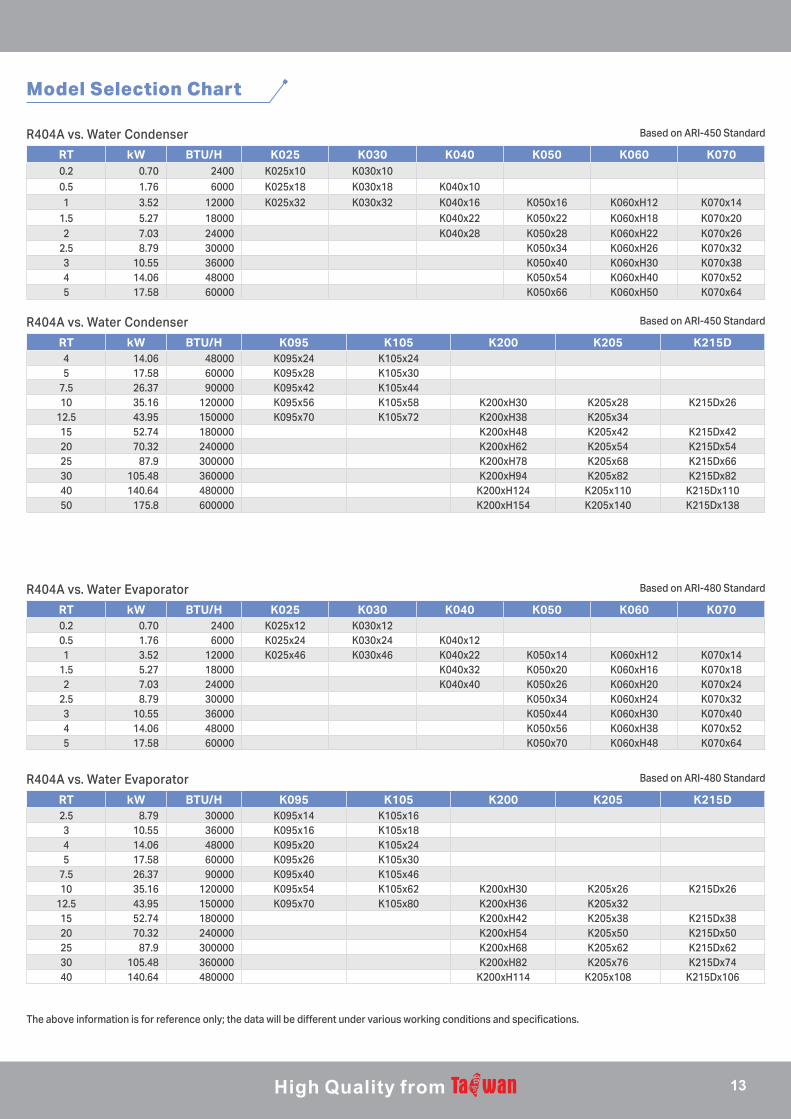
R404A vs. Water Condenser
R404A vs. Water Evaporator
R404A vs. Water Condenser
R404A vs. Water Evaporator
Based on ARI-450 Standard
Based on ARI-480 Standard
Based on ARI-450 Standard
Based on ARI-480 Standard
The above information is for reference only; the data will be different under various working conditions and specifications.
Model Selection Chart
RT kW BTU/H K025 K030 K040 K050 K060 K0700.2 0.70 2400 K025x10 K030x100.5 1.76 6000 K025x18 K030x18 K040x101 3.52 12000 K025x32 K030x32 K040x16 K050x16 K060xH12 K070x14
1.5 5.27 18000 K040x22 K050x22 K060xH18 K070x202 7.03 24000 K040x28 K050x28 K060xH22 K070x26
2.5 8.79 30000 K050x34 K060xH26 K070x323 10.55 36000 K050x40 K060xH30 K070x384 14.06 48000 K050x54 K060xH40 K070x525 17.58 60000 K050x66 K060xH50 K070x64
RT kW BTU/H K025 K030 K040 K050 K060 K0700.2 0.70 2400 K025x12 K030x120.5 1.76 6000 K025x24 K030x24 K040x121 3.52 12000 K025x46 K030x46 K040x22 K050x14 K060xH12 K070x14
1.5 5.27 18000 K040x32 K050x20 K060xH16 K070x182 7.03 24000 K040x40 K050x26 K060xH20 K070x24
2.5 8.79 30000 K050x34 K060xH24 K070x323 10.55 36000 K050x44 K060xH30 K070x404 14.06 48000 K050x56 K060xH38 K070x525 17.58 60000 K050x70 K060xH48 K070x64
RT kW BTU/H K095 K105 K200 K205 K215D4 14.06 48000 K095x24 K105x245 17.58 60000 K095x28 K105x30
7.5 26.37 90000 K095x42 K105x4410 35.16 120000 K095x56 K105x58 K200xH30 K205x28 K215Dx26
12.5 43.95 150000 K095x70 K105x72 K200xH38 K205x3415 52.74 180000 K200xH48 K205x42 K215Dx4220 70.32 240000 K200xH62 K205x54 K215Dx5425 87.9 300000 K200xH78 K205x68 K215Dx6630 105.48 360000 K200xH94 K205x82 K215Dx8240 140.64 480000 K200xH124 K205x110 K215Dx11050 175.8 600000 K200xH154 K205x140 K215Dx138
RT kW BTU/H K095 K105 K200 K205 K215D2.5 8.79 30000 K095x14 K105x163 10.55 36000 K095x16 K105x184 14.06 48000 K095x20 K105x245 17.58 60000 K095x26 K105x30
7.5 26.37 90000 K095x40 K105x4610 35.16 120000 K095x54 K105x62 K200xH30 K205x26 K215Dx26
12.5 43.95 150000 K095x70 K105x80 K200xH36 K205x3215 52.74 180000 K200xH42 K205x38 K215Dx3820 70.32 240000 K200xH54 K205x50 K215Dx5025 87.9 300000 K200xH68 K205x62 K215Dx6230 105.48 360000 K200xH82 K205x76 K215Dx7440 140.64 480000 K200xH114 K205x108 K215Dx106
13

R Series-High Heat Transfer Performance Brazed Plate Heat Exchanger
R Series high heat transfer BPHE is designed with micro channel pattern, it is
specially designed for high enthalpy refrigerant. This makes R series to perform
better than K series. Compact design also reduce the thickness, weight and
internal volume of the BPHE, making the installation easier.
Applicable refrigerants: R32, R290, R445B, R410A new generation eco-friendly
refrigerants.
Main Application: Heat pump, chiller and HVAC system.
Brazing Material Copper Copper(Extra Strength)
Model
R020, R040, R050, R095, R200, R215
R021, R041, R051, R096, R201, R216
(A1,A2/B1,B2)
Max. Working Pressure (bar) 30/30 45/30
Max. Working Temperature (°C) 200°C
Model L1(mm)
L2(mm)
W1(mm)
W2(mm)
HThickness
(mm)
Weight*(kg)(Without Connection)
Heat Transfer
Area/ plate (m2)
Total Heat Transfer Area
(m2)
Volume/ Channel
(liter)
Total Volume
(liter)
R020 191 154 77 40 7.0+1.15*N 0.62+0.042*N 0.0111 (N-2)*0.0111 0.009 (N-1)*0.009R040 311 278 73 40 7.5+1.30*N 0.63+0.070*N 0.0195 (N-2)*0.0195 0.017 (N-1)*0.017R050 306 250 106 50 9.3+1.80*N 1.20+0.089*N 0.0255 (N-2)*0.0255 0.038 (N-1)*0.038R095 522 466 106 50 10.0+1.85*N 2.75+0.160*N 0.0475 (N-2)*0.0475 0.076 (N-1)*0.076R200 613 519 186 92 14.0+2.05*N 6.94+0.385*N 0.0945 (N-2)*0.0945 0.175 (N-1)*0.175R215 529 449 247 167 14.0+1.85*N 7.92+0.430*N 0.1103 (N-2)*0.1103 0.187 (N-1)*0.187
Model L1(mm)
L2(mm)
W1(mm)
W2(mm)
HThickness
(mm)
Weight*(kg)(Without Connection)
Heat Transfer
Area/ plate (m2)
Total Heat Transfer Area
(m2)
Volume/ Channel
(liter)
Total Volume
(liter)
R021 191 154 77 40 7.0+1.15*N 0.62+0.042*N 0.0111 (N-2)*0.0111 0.009 (N-1)*0.009R041 311 278 73 40 7.5+1.30*N 0.63+0.070*N 0.0195 (N-2)*0.0195 0.017 (N-1)*0.017R051 306 250 106 50 11.3+1.80*N 2.22+0.089*N 0.0255 (N-2)*0.0255 0.038 (N-1)*0.038R096 522 466 106 50 10.0+1.80*N 2.83+0.160*N 0.0475 (N-2)*0.0475 0.076 (N-1)*0.076R201 613 519 186 92 17.0+2.05*N 11.83+0.385*N 0.0945 (N-2)*0.0945 0.175 (N-1)*0.175R216 529 449 247 167 17.0+1.85*N 13.51+0.430*N 0.1103 (N-2)*0.1103 0.187 (N-1)*0.187
N: number of plates
Model Selection ChartR290 vs. Water Condenser Based on ARI-450 Standard
RT kW BTU/H R020 R040 R050 R0950.2 0.7 2400 R020Hx80.5 1.76 6000 R020Hx141 3.52 12000 R020Hx22 R050x10
1.5 5.27 18000 R020Hx32 R040x18 R050x142 7.03 24000 R020Hx42 R040x24 R050x18
2.5 8.79 30000 R040x30 R050x22
RT kW BTU/H R020 R040 R050 R0953 10.55 36000 R040x38 R050x264 14.06 48000 R050x34 R095Mx205 17.58 60000 R050x42 R095Mx24
7.5 26.37 90000 R050x60 R095Mx3610 35.16 120000 R050x80 R095Mx46
12.5 43.95 150000 R095Mx5815 52.74 180000 R095Mx70
B1 C1
B2 C2
R215D/R216D: Dual Circuits- 6 Connections
14
The above information is for reference only; the data will be different under various working conditions and specifications.
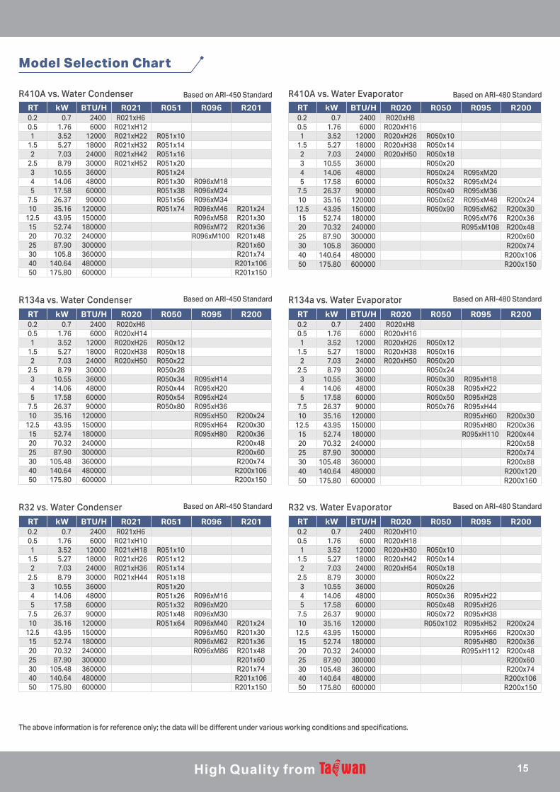
Model Selection Chart
R410A vs. Water Condenser R410A vs. Water EvaporatorBased on ARI-450 Standard Based on ARI-480 Standard
RT kW BTU/H R021 R051 R096 R2010.2 0.7 2400 R021xH60.5 1.76 6000 R021xH121 3.52 12000 R021xH22 R051x10
1.5 5.27 18000 R021xH32 R051x142 7.03 24000 R021xH42 R051x16
2.5 8.79 30000 R021xH52 R051x203 10.55 36000 R051x244 14.06 48000 R051x30 R096xM185 17.58 60000 R051x38 R096xM24
7.5 26.37 90000 R051x56 R096xM3410 35.16 120000 R051x74 R096xM46 R201x24
12.5 43.95 150000 R096xM58 R201x3015 52.74 180000 R096xM72 R201x3620 70.32 240000 R096xM100 R201x4825 87.90 300000 R201x6030 105.8 360000 R201x7440 140.64 480000 R201x10650 175.80 600000 R201x150
RT kW BTU/H R020 R050 R095 R2000.2 0.7 2400 R020xH80.5 1.76 6000 R020xH161 3.52 12000 R020xH26 R050x10
1.5 5.27 18000 R020xH38 R050x142 7.03 24000 R020xH50 R050x183 10.55 36000 R050x204 14.06 48000 R050x24 R095xM205 17.58 60000 R050x32 R095xM24
7.5 26.37 90000 R050x40 R095xM3610 35.16 120000 R050x62 R095xM48 R200x24
12.5 43.95 150000 R050x90 R095xM62 R200x3015 52.74 180000 R095xM76 R200x3620 70.32 240000 R095xM108 R200x4825 87.90 300000 R200x6030 105.8 360000 R200x7440 140.64 480000 R200x10650 175.80 600000 R200x150
R134a vs. Water Condenser R134a vs. Water EvaporatorBased on ARI-450 Standard Based on ARI-480 Standard
RT kW BTU/H R020 R050 R095 R2000.2 0.7 2400 R020xH60.5 1.76 6000 R020xH141 3.52 12000 R020xH26 R050x12
1.5 5.27 18000 R020xH38 R050x182 7.03 24000 R020xH50 R050x22
2.5 8.79 30000 R050x283 10.55 36000 R050x34 R095xH144 14.06 48000 R050x44 R095xH205 17.58 60000 R050x54 R095xH24
7.5 26.37 90000 R050x80 R095xH3610 35.16 120000 R095xH50 R200x24
12.5 43.95 150000 R095xH64 R200x3015 52.74 180000 R095xH80 R200x3620 70.32 240000 R200x4825 87.90 300000 R200x6030 105.48 360000 R200x7440 140.64 480000 R200x10650 175.80 600000 R200x150
RT kW BTU/H R020 R050 R095 R2000.2 0.7 2400 R020xH80.5 1.76 6000 R020xH161 3.52 12000 R020xH26 R050x12
1.5 5.27 18000 R020xH38 R050x162 7.03 24000 R020xH50 R050x20
2.5 8.79 30000 R050x243 10.55 36000 R050x30 R095xH184 14.06 48000 R050x38 R095xH225 17.58 60000 R050x50 R095xH28
7.5 26.37 90000 R050x76 R095xH4410 35.16 120000 R095xH60 R200x30
12.5 43.95 150000 R095xH80 R200x3615 52.74 180000 R095xH110 R200x4420 70.32 240000 R200x5825 87.90 300000 R200x7430 105.48 360000 R200x8840 140.64 480000 R200x12050 175.80 600000 R200x160
R32 vs. Water Condenser R32 vs. Water EvaporatorBased on ARI-450 Standard Based on ARI-480 Standard
RT kW BTU/H R021 R051 R096 R2010.2 0.7 2400 R021xH60.5 1.76 6000 R021xH101 3.52 12000 R021xH18 R051x10
1.5 5.27 18000 R021xH26 R051x122 7.03 24000 R021xH36 R051x14
2.5 8.79 30000 R021xH44 R051x183 10.55 36000 R051x204 14.06 48000 R051x26 R096xM165 17.58 60000 R051x32 R096xM20
7.5 26.37 90000 R051x48 R096xM3010 35.16 120000 R051x64 R096xM40 R201x24
12.5 43.95 150000 R096xM50 R201x3015 52.74 180000 R096xM62 R201x3620 70.32 240000 R096xM86 R201x4825 87.90 300000 R201x6030 105.48 360000 R201x7440 140.64 480000 R201x10650 175.80 600000 R201x150
RT kW BTU/H R020 R050 R095 R2000.2 0.7 2400 R020xH100.5 1.76 6000 R020xH181 3.52 12000 R020xH30 R050x10
1.5 5.27 18000 R020xH42 R050x142 7.03 24000 R020xH54 R050x18
2.5 8.79 30000 R050x223 10.55 36000 R050x264 14.06 48000 R050x36 R095xH225 17.58 60000 R050x48 R095xH26
7.5 26.37 90000 R050x72 R095xH3810 35.16 120000 R050x102 R095xH52 R200x24
12.5 43.95 150000 R095xH66 R200x3015 52.74 180000 R095xH80 R200x3620 70.32 240000 R095xH112 R200x4825 87.90 300000 R200x6030 105.48 360000 R200x7440 140.64 480000 R200x10650 175.80 600000 R200x150
15
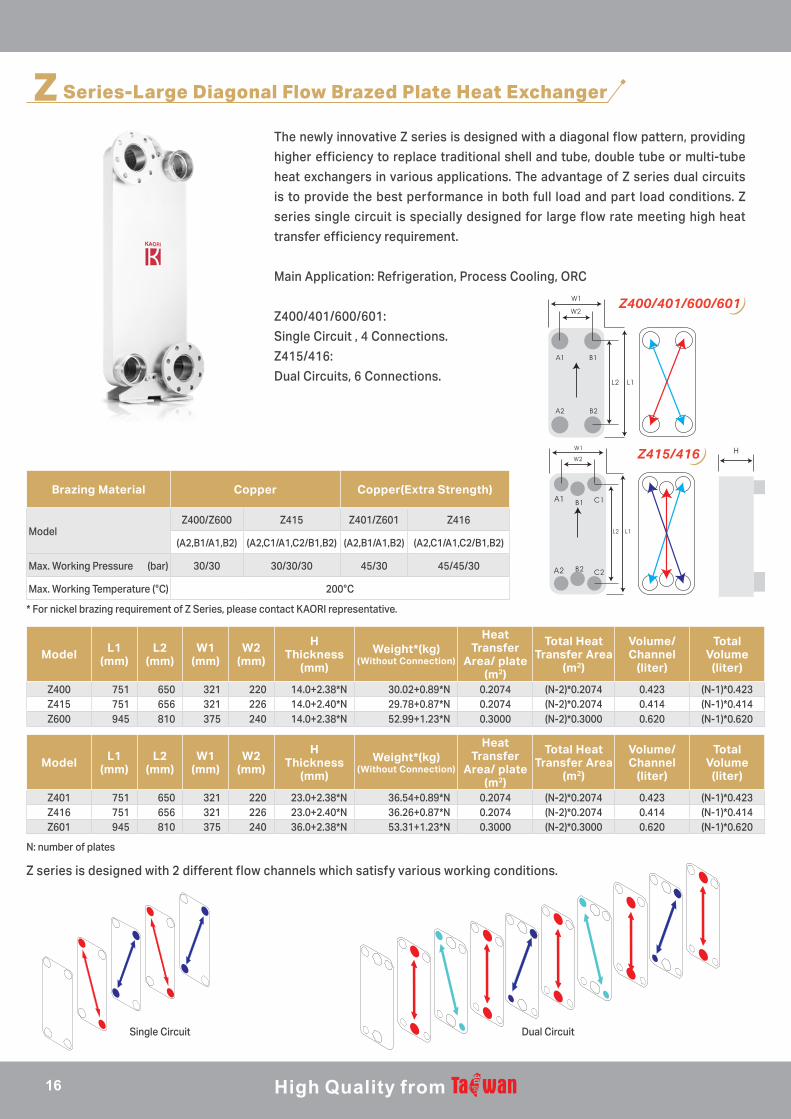
The newly innovative Z series is designed with a diagonal flow pattern, providing
higher efficiency to replace traditional shell and tube, double tube or multi-tube
heat exchangers in various applications. The advantage of Z series dual circuits
is to provide the best performance in both full load and part load conditions. Z
series single circuit is specially designed for large flow rate meeting high heat
transfer efficiency requirement.
Main Application: Refrigeration, Process Cooling, ORC
Z400/401/600/601:
Single Circuit , 4 Connections.
Z415/416:
Dual Circuits, 6 Connections.
B1 C1
B2 C2
Z400/401/600/601
Z Series-Large Diagonal Flow Brazed Plate Heat Exchanger
Brazing Material Copper Copper(Extra Strength)
ModelZ400/Z600 Z415 Z401/Z601 Z416
(A2,B1/A1,B2) (A2,C1/A1,C2/B1,B2) (A2,B1/A1,B2) (A2,C1/A1,C2/B1,B2)
Max. Working Pressure (bar) 30/30 30/30/30 45/30 45/45/30
Max. Working Temperature (°C) 200°C
Model L1(mm)
L2(mm)
W1(mm)
W2(mm)
HThickness
(mm)
Weight*(kg)(Without Connection)
Heat Transfer
Area/ plate (m2)
Total Heat Transfer Area
(m2)
Volume/ Channel
(liter)
Total Volume
(liter)
Z400 751 650 321 220 14.0+2.38*N 30.02+0.89*N 0.2074 (N-2)*0.2074 0.423 (N-1)*0.423Z415 751 656 321 226 14.0+2.40*N 29.78+0.87*N 0.2074 (N-2)*0.2074 0.414 (N-1)*0.414Z600 945 810 375 240 14.0+2.38*N 52.99+1.23*N 0.3000 (N-2)*0.3000 0.620 (N-1)*0.620
Model L1(mm)
L2(mm)
W1(mm)
W2(mm)
HThickness
(mm)
Weight*(kg)(Without Connection)
Heat Transfer
Area/ plate (m2)
Total Heat Transfer Area
(m2)
Volume/ Channel
(liter)
Total Volume
(liter)
Z401 751 650 321 220 23.0+2.38*N 36.54+0.89*N 0.2074 (N-2)*0.2074 0.423 (N-1)*0.423Z416 751 656 321 226 23.0+2.40*N 36.26+0.87*N 0.2074 (N-2)*0.2074 0.414 (N-1)*0.414Z601 945 810 375 240 36.0+2.38*N 53.31+1.23*N 0.3000 (N-2)*0.3000 0.620 (N-1)*0.620
N: number of plates
Single Circuit Dual Circuit
Z series is designed with 2 different flow channels which satisfy various working conditions.
Z415/416
* For nickel brazing requirement of Z Series, please contact KAORI representative.
16
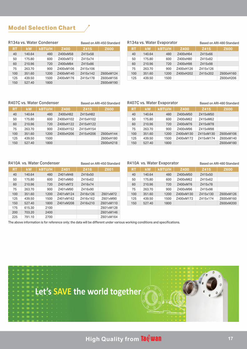
RT kW kBTU/H Z400 Z415 Z60040 140.64 480 Z400xM58 Z415x5850 175.80 600 Z400xM72 Z415x7460 210.96 720 Z400xM84 Z415x8675 263.70 900 Z400xM106 Z415x106
100 351.60 1200 Z400xM140 Z415x142 Z600xM124125 439.50 1500 Z400xM176 Z415x178 Z600xM156150 527.40 1800 Z600xM190
RT kW kBTU/H Z400 Z415 Z60040 140.64 480 Z400xH64 Z415x6650 175.80 600 Z400xH80 Z415x8260 210.96 720 Z400xH98 Z415x9875 263.70 900 Z400xH126 Z415x126
100 351.60 1200 Z400xH202 Z415x202 Z600xH160125 439.50 1500 Z600xH206
R134a vs. Water Condenser R134a vs. Water EvaporatorBased on ARI-450 Standard Based on ARI-480 Standard
Model Selection Chart
RT kW kBTU/H Z400 Z415 Z60040 140.64 480 Z400xM50 Z415x5050 175.80 600 Z400xM62 Z415x6260 210.96 720 Z400xM76 Z415x7875 263.70 900 Z400xM96 Z415x98
100 351.60 1200 Z400xM130 Z415x130 Z600xM126125 439.50 1500 Z400xM172 Z415x174 Z600xM160150 527.40 1800 Z600xM200
R410A vs. Water Condenser R410A vs. Water EvaporatorBased on ARI-450 Standard Based on ARI-480 Standard
The above information is for reference only; the data will be different under various working conditions and specifications.
R407C vs. Water Condenser R407C vs. Water EvaporatorBased on ARI-450 Standard Based on ARI-480 Standard
RT kW kBTU/H Z400 Z415 Z60040 140.64 480 Z400xH82 Z415xH8250 175.80 600 Z400xH102 Z415xH10260 210.96 720 Z400xH122 Z415xH12275 263.70 900 Z400xH152 Z415xH154
100 351.60 1200 Z400xH206 Z415xH206 Z600xH144125 439.50 1500 Z600xH180150 527.40 1800 Z600xH218
RT kW kBTU/H Z400 Z415 Z60040 140.64 480 Z400xM50 Z415xM5050 175.80 600 Z400xM62 Z415xM6260 210.96 720 Z400xM76 Z415xM7875 263.70 900 Z400xM96 Z415xM98
100 351.60 1200 Z400xM130 Z415xM130 Z600xM106125 439.50 1500 Z400xM172 Z415xM174 Z600xM140150 527.40 1800 Z600xM180
RT kW kBTU/H Z401 Z416 Z60140 140.64 480 Z401xM48 Z416x5050 175.80 600 Z401xM60 Z416x6260 210.96 720 Z401xM72 Z416x7475 263.70 900 Z401xM90 Z416x90
100 351.60 1200 Z401xM124 Z416x126 Z601xM72125 439.50 1500 Z401xM162 Z416x162 Z601xM90150 527.40 1800 Z401xM208 Z416x210 Z601xM110175 615.30 2100 Z601xM128200 703.20 2400 Z601xM146225 791.10 2700 Z601xM164
17

C Series-CO2 Super High Pressure Brazed Plate Heat Exchanger
KAORI patented solution with C series is specially designed for Gas cooler,
condenser, evaporator and economizer in R744 (CO2) heat pump and refrigeration
system. Different designs with max. working pressure 140 bar, 100 bar and 70
bar are available for Supercritical, Transcritical and Subcritical CO2 heating and
cooling systems.
Compact size, outstanding heat transfer performance and low pressure drop
are the three key features. The quality and the durability of C series is proven by
thorough inspection, achieving the burst test pressure up to 650 bar and cycle
test over 100,000 cycles.
Brazing Material Copper
Model
C020,C040C095,C200
C021,C041C096,C201
C022,C042C097,C202
(A1,A2/B1,B2)
Max. Working Pressure (bar) 70/30* 100/30* 140/30*
Max. Working Temperature (°C) 200°C
Model L1(mm)
L2(mm)
W1(mm)
W2(mm)
HThickness
(mm)
Weight*(kg)(Without Connection)
Heat Transfer
Area/ plate (m2)
Total Heat Transfer Area
(m2)
Volume/ Channel
(liter)
Total Volume
(liter)
C020 191 154 77 40 9.5+1.10*N 1.12+0.042*N 0.0111 (N-2)*0.0111 0.009 (N-1)*0.009C040 314 275 76 40 13.0+2.00*N 1.74+0.145*N 0.0193 (N-2)*0.0193 0.030 (N-1)*0.030C095 524 466 108 50 13.2+2.16*N 5.52+0.320*N 0.0475 (N-2)*0.0475 0.071 (N-1)*0.071C200 616 519 189 92 14.0+2.15*N 12.39+0.603*N 0.0950 (N-2)*0.0950 0.156 (N-1)*0.156
Model L1(mm)
L2(mm)
W1(mm)
W2(mm)
HThickness
(mm)
Weight*(kg)(Without Connection)
Heat Transfer
Area/ plate (m2)
Total Heat Transfer Area
(m2)
Volume/ Channel
(liter)
Total Volume
(liter)
C021 191 154 77 40 9.5+1.10*N 1.14+0.042*N 0.0111 (N-4)*0.0111 0.009 (N-3)*0.009C041 314 275 76 40 13.0+2.00*N 1.83+0.145*N 0.0193 (N-2)*0.0193 0.030 (N-1)*0.030C096 524 466 108 50 13.2+2.16*N 5.68+0.320*N 0.0475 (N-2)*0.0475 0.071 (N-1)*0.071C201 616 519 189 92 14.0+2.15*N 12.56+0.631*N 0.0950 (N-2)*0.0950 0.156 (N-1)*0.156
Model L1(mm)
L2(mm)
W1(mm)
W2(mm)
HThickness
(mm)
Weight*(kg)(Without Connection)
Heat Transfer
Area/ plate (m2)
Total Heat Transfer Area
(m2)
Volume/ Channel
(liter)
Total Volume
(liter)
C022 191 154 77 40 9.5+1.10*N 1.126+0.042*N 0.0111 (N-6)*0.0111 0.009 (N-5)*0.009C042 314 275 76 40 13.0+2.00*N 1.75+0.152*N 0.0193 (N-2)*0.0193 0.030 (N-1)*0.030C097 524 466 108 50 13.2+2.16*N 5.90+0.346*N 0.0475 (N-2)*0.0475 0.071 (N-1)*0.071C202 616 519 189 92 14.0+2.15*N 12.41+0.755*N 0.0950 (N-2)*0.0950 0.156 (N-1)*0.156
* For higher working pressure request on B1/B2, please contact KAORI representative.
N: number of plates
18

RT kW BTU/H C020/C021/C022 C040/C041/C042 C095/C096/C097 C200/C201/C202
1 3.52 12000 C022xH36 (4 Pass) C042x24 (4 Pass)
1.5 5.27 18000 C022xH44 (4 Pass) C042x32 (4 Pass)
2 7.03 24000 C022xH52 (4 Pass) C042x40 (4 Pass) C097x24 (4 Pass)
3 10.55 36000 C097x24 (4 Pass)
4 14.06 48000 C097x32 (4 Pass)
5 17.58 60000 C097x40 (4 Pass) C202xH24 (3 Pass)
7.5 26.37 90000 C097x48 (4 Pass) C202xH30 (3 Pass)
10 35.16 120000 C097x64 (4 Pass) C202xH36 (3 Pass)
12.5 43.95 150000 C097x72 (4 Pass) C202xH48 (3 Pass)
15 52.74 180000 C097x88 (4 Pass) C202xH54 (3 Pass)
20 70.32 240000 C202xH66 (3 Pass)
25 87.90 300000 C202xH84 (3 Pass)
30 105.48 360000 C202xH102 (3 Pass)
35 123.06 420000 C202xH114 (3 Pass)
40 140.64 480000 C0202xH132 (3 Pass)
R744 vs. Water Gas Cooler (Max. Working Pressure : 140bar)
The above information is for reference only; the data will be different under various working conditions and specifications.
Water to Water
Hot Water
Tap Water
Heat Pump Unit
Tank Unit
CO2 to Water Circulation PumpThree Way ValveMixing ValveSafety Relief Valve
Low Temperature
High Temperature Hot Water
Water
Evaporator
ExpansionValve
Compressor
GasCooler
CO2Refrigerant
cycle
Water to WaterHeat Exchanger
Model Selection Chart
CO2 Heat Pump System
19
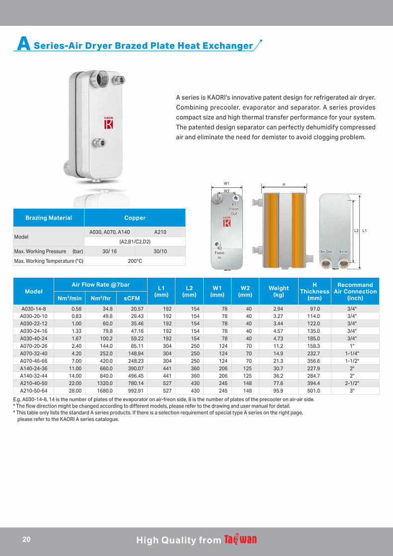
A Series-Air Dryer Brazed Plate Heat Exchanger
A series is KAORI's innovative patent design for refrigerated air dryer.
Combining precooler, evaporator and separator. A series provides
compact size and high thermal transfer performance for your system.
The patented design separator can perfectly dehumidify compressed
air and eliminate the need for demister to avoid clogging problem.
ModelAir Flow Rate @7bar
L1(mm)
L2(mm)
W1(mm)
W2(mm)
Weight(kg)
HThickness
(mm)
Recommand Air Connection
(inch)Nm3/min Nm3/hr sCFM
A030-14-8 0.58 34.8 20.57 192 154 78 40 2.94 97.0 3/4"A030-20-10 0.83 49.8 29.43 192 154 78 40 3.27 114.0 3/4"A030-22-12 1.00 60.0 35.46 192 154 78 40 3.44 122.0 3/4"A030-24-16 1.33 79.8 47.16 192 154 78 40 4.57 135.0 3/4"A030-40-24 1.67 100.2 59.22 192 154 78 40 4.73 185.0 3/4"A070-20-26 2.40 144.0 85.11 304 250 124 70 11.2 158.3 1"A070-32-40 4.20 252.0 148.94 304 250 124 70 14.9 232.7 1-1/4"A070-46-66 7.00 420.0 248.23 304 250 124 70 21.3 356.6 1-1/2"A140-24-36 11.00 660.0 390.07 441 360 206 125 30.7 227.9 2"A140-32-44 14.00 840.0 496.45 441 360 206 125 36.2 284.7 2"A210-40-50 22.00 1320.0 780.14 527 430 245 148 77.6 394.4 2-1/2"A210-50-64 28.00 1680.0 992.91 527 430 245 148 95.9 501.0 3"
E.g. A030-14-8, 14 is the number of plates of the evaporator on air-freon side, 8 is the number of plates of the precooler on air-air side.* The flow direction might be changed according to different models, please refer to the drawing and user manual for detail. * This table only lists the standard A series products. If there is a selection requirement of special type A series on the right page, please refer to the KAORI A series catalogue.
Brazing Material Copper
ModelA030, A070, A140 A210
(A2,B1/C2,D2)
Max. Working Pressure (bar) 30/ 16 30/10
Max. Working Temperature (°C) 200°C
L1L2
Air InAir InAir OutAir Out
W1
W2
B1B1FreonFreon
OutOut
A2A2FreonFreon
InIn
H
20

Compressed air outlet
High pressure gauge
Filter
Capillary tube
Fan motorcontrol switch High pressure switch
PS2 PS1
P
Low pressure gauge
Drainer
Compressed air inlet
Charge valve
Hot gasbypass valve
P
Compressor
Condenser(with fan & motor)
A Series Freon in Air in
Freon out Air out
A Sereis Air Dryer System Chart
A070-20-26A-G
Types Standard High-Pressure Air Type
T TypeChilled Outlet Air
G TypeHigh-Pressure
Refrigerant
D TypeDesiccant/
Refrigerated Combination
R TypeRefrigerant Heat
Recovery
Characteristic Standard 3-in-1 Heat Exchangers
Suitable for High-pressure Air up to 45 Bar
Chilled Dry Compressed Air
2-in-1 Heat Exchanger
Suitable for High-pressure Refrigerant up to 45 Bar
For Combined DryersSystems Downsized
by 50%
Heat-pump-integrated Refrigerated Air Dryers
for Energy Conservations
Applications Refrigerated Air Dryers
PET, Blowing Molding, Pharmaceutical
Packaging, and Injection Molding Machines
Semiconductor Related Manufacturing, Food
Processing, Coating, Air Bearing, and Injection
Molding Machines
For Refrigerated Air Dryer Applications under High
Ambient Temperature
Semiconductor and Precision Manufacturing
Related Industries
Machines with Compact Compressed Air
Temperature Control Equipments
Connectors Stainless Steel SUS 304
Plates、Separators Stainless Steel SUS 304
Welding materials 99.9% Copper
A030 ● ● ● ● ●A070 ● ● ● ● ● ●A140 ● ● ●A210 ● ● ●
Series Model Air Side Pressure0:Standard 16 bar2:High Pressure45 bar
Evaporator Plates Pre-cooler Plates Separator Size TypeEx :G Type-High-Pressure
Refrigerant
A Series Model and Product Code Illustrations
21

Model L1(mm)
L2(mm)
W1(mm)
W2(mm)
HThickness
(mm)
Weight*(kg)(Without
Connection)
Heat Transfer
Area/ plate (m2)
Total Heat Transfer Area
(m2)
Volume/ Channel
(liter)
Total Volume
(liter)
D031 202 156 92 46 9.0+2.40*N 0.71+0.104*N 0.013 (N-2)*0.013 0.027 (N-1)*0.027D046* 363 320 82 40 8.3+2.02*N 1.18+0.166*N 0.024 (N-2)*0.024 0.030 (N-1)*0.030D071 306 250 126 70 11.3+2.60*N 2.65+0.218*N 0.030 (N-2)*0.030 0.059 (N-1)*0.059
N: number of plates* D045/ D046: diagonal design.
Brazing Material Copper
ModelD030, D045, D070 D031,D046 D071
(A1,A2/B1,B2)
Max. Working Pressure (bar) 30/30 45/45 40/30
Max. Working Temperature (°C) 200°C
D Series-Double Wall Brazed Plate Heat Exchanger
To prevent two different kinds of fluid from intermixing caused by
internal leakage, KAORI precisely designed D Series solution with
the double-stacked plates, eliminating the possibility of cross
contamination.
The unique air gap is created between the two plates. Once internal
leakage occurs, the 2nd plate becomes a shield to keep fluid stay and
flow on the same channel through the air gap. Meanwhile, vent holes
outside the plate will seep out fluid as an indication of leakage.
Model L1(mm)
L2(mm)
W1(mm)
W2(mm)
HThickness
(mm)
Weight*(kg)(Without
Connection)
Heat Transfer
Area/ plate (m2)
Total Heat Transfer Area
(m2)
Volume/ Channel
(liter)
Total Volume
(liter)
D030 202 156 92 46 8.0+2.40*N 0.45+0.104*N 0.013 (N-2)*0.013 0.027 (N-1)*0.027D045* 363 320 82 40 8.3+2.02*N 1.00+0.166*N 0.024 (N-2)*0.024 0.030 (N-1)*0.030D070 306 250 126 70 9.3+2.60*N 1.53+0.203*N 0.030 (N-2)*0.030 0.059 (N-1)*0.059
Double Wall Vs. Regular BPHE
KAORI Double Wall Regular BPHE
The cracks on plates result in internal The cracks on plates result in internal leakage between fluids, which can’t leakage between fluids, which can’t be distinguished from outer surfacebe distinguished from outer surface
The cracks on plates doesn’t lead to The cracks on plates doesn’t lead to internal leakage between fluids, which can internal leakage between fluids, which can be distinguished from outer appearance.be distinguished from outer appearance.
B1 C1
B2 C2
D045/046
22

E SeriesF Series
E/F Series-Low Pressure Brazed Plate Heat Exchanger
E/ F series is designed for the specification of small volume water to
water application. E series is flat cover plate design and F series is
economical design (without flat cover plate); also, multi-pass pattern
are available upon different working conditions and requests.
Main application: Residential Gas Boiler, District Heating, Solar
Heating System.
Brazing Material Copper
ModelE010, E015, F015, E030, E040 E050, E060
(A1,A2/B1,B2)
Max. Working Pressure (bar) 20/20 10/10
Max. Working Temperature (°C) 200°C
Model L1(mm)
L2(mm)
W1(mm)
W2(mm)
HThickness
(mm)
Weight*(kg)(Without
Connection)
Heat Transfer
Area/ plate (m2)
Total Heat Transfer Area
(m2)
Volume/ Channel
(liter)
Total Volume
(liter)
E010 137 110 62 26 6.5+1.7*N 0.147+0.024*N 0.0064 (N-2)*0.0064 0.011 (N-1)*0.011E015 155 120 75 40 9.0+1.80*N 0.21+0.036*N 0.0084 (N-2)*0.0084 0.016 (N-1)*0.016F025 206 172 73 40/42 6.5+2.27*(N-2) 0.19+0.040*(N-2) 0.0120 (N-2)*0.0120 0.025 (N-1)*0.025E030 195 154 80 40 7.0+2.25*N 0.29+0.047*N 0.0117 (N-2)*0.0117 0.025 (N-1)*0.025E040 311 278 73 40 9.0+2.30*N 0.62+0.070*N 0.0195 (N-2)*0.0195 0.040 (N-1)*0.040E050 306 250 106 50 9.0+2.38*N 1.15+0.116*N 0.0255 (N-2)*0.0255 0.055 (N-1)*0.055E060 466 432 74 40 9.0+2.30*N 0.66+0.100*N 0.0302 (N-2)*0.0302 0.064 (N-1)*0.064
N: number of plates
The above information is for reference only; the data will be different under various working conditions and specifications.
Model Selection Chart
RT kW BTU/H Hot Water Temp. Cold Water Temp. E015 F025 E030 E040 E060
1 3.5160 12000 70°C --> 50°C 10°C --> 60°C E015x14 F025x12 E030x122 7.0320 24000 70°C --> 50°C 10°C --> 60°C E015x18 F025x16 E030x163 10.5480 36000 70°C --> 50°C 10°C --> 60°C E015x26 F025x22 E030x224 14.0640 48000 70°C --> 50°C 10°C --> 60°C E015x30 F025x26 E030x265 17.5800 60000 70°C --> 50°C 10°C --> 60°C F025x32 E030x32 E040x10
7.5 26.3700 90000 70°C --> 50°C 10°C --> 60°C F025x44 E030x44 E040x14 E060xH1010 35.1600 120000 70°C --> 50°C 10°C --> 60°C F025x56 E030x56 E040x18 E060xH1215 52.7400 180000 70°C --> 50°C 10°C --> 60°C E040x26 E060xH1820 70.3200 240000 70°C --> 50°C 10°C --> 60°C E040x36 E060xH2425 87.9000 300000 70°C --> 50°C 10°C --> 60°C E040x50 E060xH3030 105.480 360000 70°C --> 50°C 10°C --> 60°C E060xH40
23
Model L1(mm)
L2(mm)
W1(mm)
W2(mm)
HThickness
(mm)
Weight*(kg)(Without
Connection)
Heat Transfer
Area/ plate (m2)
Total Heat Transfer Area
(m2)
Volume/ Channel
(liter)
Total Volume
(liter)
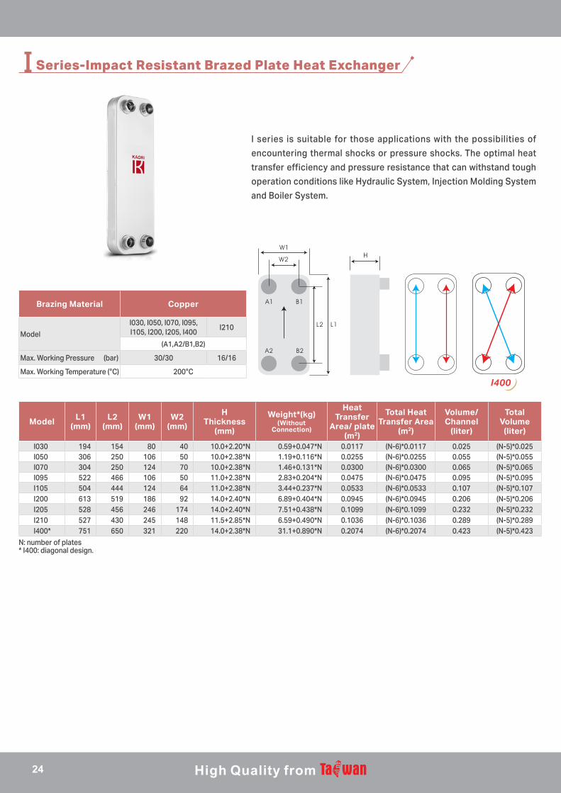
I030 194 154 80 40 10.0+2.20*N 0.59+0.047*N 0.0117 (N-6)*0.0117 0.025 (N-5)*0.025I050 306 250 106 50 10.0+2.38*N 1.19+0.116*N 0.0255 (N-6)*0.0255 0.055 (N-5)*0.055I070 304 250 124 70 10.0+2.38*N 1.46+0.131*N 0.0300 (N-6)*0.0300 0.065 (N-5)*0.065I095 522 466 106 50 11.0+2.38*N 2.83+0.204*N 0.0475 (N-6)*0.0475 0.095 (N-5)*0.095I105 504 444 124 64 11.0+2.38*N 3.44+0.237*N 0.0533 (N-6)*0.0533 0.107 (N-5)*0.107I200 613 519 186 92 14.0+2.40*N 6.89+0.404*N 0.0945 (N-6)*0.0945 0.206 (N-5)*0.206I205 528 456 246 174 14.0+2.40*N 7.51+0.438*N 0.1099 (N-6)*0.1099 0.232 (N-5)*0.232I210 527 430 245 148 11.5+2.85*N 6.59+0.490*N 0.1036 (N-6)*0.1036 0.289 (N-5)*0.289I400* 751 650 321 220 14.0+2.38*N 31.1+0.890*N 0.2074 (N-6)*0.2074 0.423 (N-5)*0.423
I Series-Impact Resistant Brazed Plate Heat Exchanger
I series is suitable for those applications with the possibilities of
encountering thermal shocks or pressure shocks. The optimal heat
transfer efficiency and pressure resistance that can withstand tough
operation conditions like Hydraulic System, Injection Molding System
and Boiler System.
N: number of plates
Brazing Material Copper
Model
I030, I050, I070, I095, I105, I200, I205, I400
I210
(A1,A2/B1,B2)
Max. Working Pressure (bar) 30/30 16/16
Max. Working Temperature (°C) 200°C
* I400: diagonal design.
B1 C1
B2 C2
I400
24
Model L1(mm)
L2(mm)
W1(mm)
W2(mm)
HThickness
(mm)
Weight*(kg)(Without Connection)
Heat Transfer
Area/ plate (m2)
Volume/ Channel
(liter)
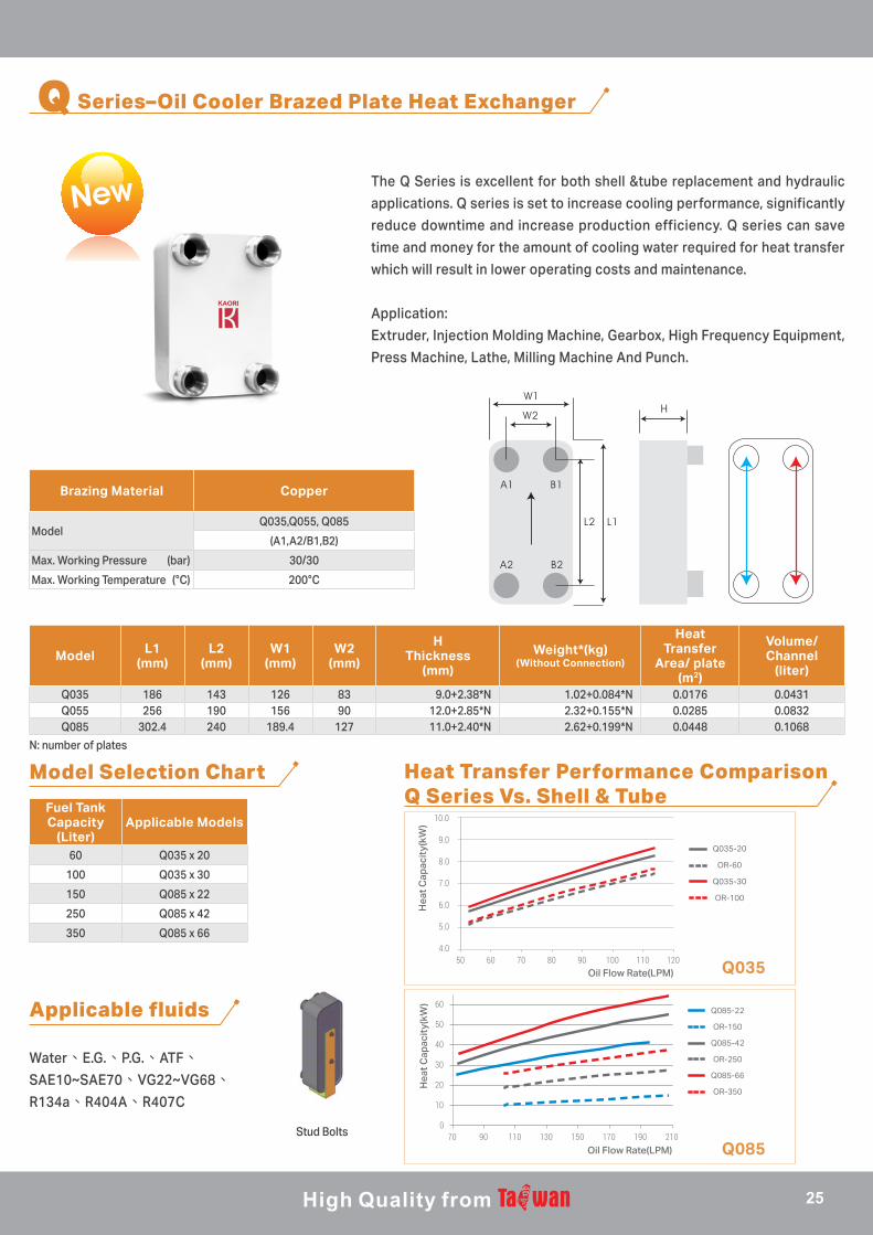
Q035 186 143 126 83 9.0+2.38*N 1.02+0.084*N 0.0176 0.0431Q055 256 190 156 90 12.0+2.85*N 2.32+0.155*N 0.0285 0.0832Q085 302.4 240 189.4 127 11.0+2.40*N 2.62+0.199*N 0.0448 0.1068
N: number of plates
Stud Bolts
Q Series–Oil Cooler Brazed Plate Heat Exchanger
The Q Series is excellent for both shell &tube replacement and hydraulic
applications. Q series is set to increase cooling performance, significantly
reduce downtime and increase production efficiency. Q series can save
time and money for the amount of cooling water required for heat transfer
which will result in lower operating costs and maintenance.
Application:
Extruder, Injection Molding Machine, Gearbox, High Frequency Equipment,
Press Machine, Lathe, Milling Machine And Punch.
Brazing Material Copper
ModelQ035,Q055, Q085
(A1,A2/B1,B2)
Max. Working Pressure (bar) 30/30
Max. Working Temperature (°C) 200°C
Fuel Tank Capacity
(Liter)Applicable Models
60 Q035 x 20
100 Q035 x 30
150 Q085 x 22
250 Q085 x 42
350 Q085 x 66
Model Selection Chart Heat Transfer Performance ComparisonQ Series Vs. Shell & Tube
Applicable fluids
Water、E.G.、P.G.、ATF、SAE10~SAE70、VG22~VG68、R134a、R404A、R407C
a.正面植釘法 b.背部植釘法 c.板金挾持法 d.旗桿與螺桿挾持法 e.腳架固定法
4.0
5.0
6.0
7.0
8.0
9.0
10.0
50 60 70 80 90 100 110 120
Q035-20
OR-60
Q035-30
OR-100
Oil Flow Rate(LPM)
Hea
t Cap
acit
y(kW
)
0
10
20
30
40
50
60
70 90 110 130 150 170 190 210
Q085-22
OR-150
Q085-42
OR-250
Q085-66
OR-350
Hea
t Cap
acit
y(kW
)
Oil Flow Rate(LPM)
4.0
5.0
6.0
7.0
8.0
9.0
10.0
50 60 70 80 90 100 110 120
Q035-20
OR-60
Q035-30
OR-100
Oil Flow Rate(LPM)
Hea
t Cap
acit
y(kW
)
0
10
20
30
40
50
60
70 90 110 130 150 170 190 210
Q085-22
OR-150
Q085-42
OR-250
Q085-66
OR-350
Hea
t Cap
acit
y(kW
)
Oil Flow Rate(LPM)
Q035
Q085
25
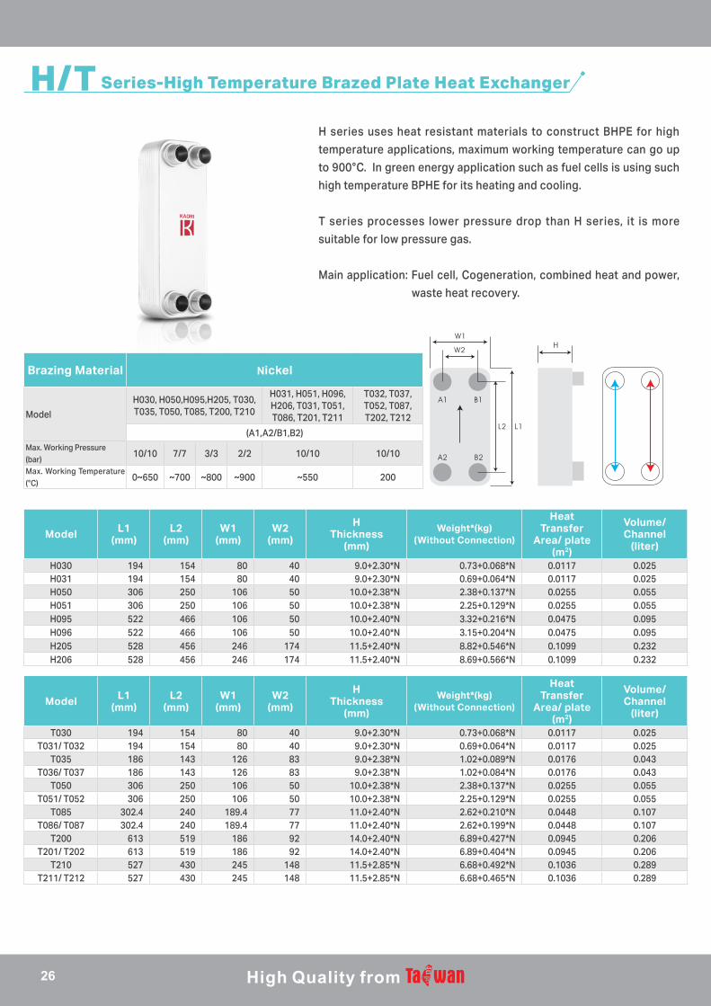
H/T Series-High Temperature Brazed Plate Heat Exchanger
H series uses heat resistant materials to construct BHPE for high
temperature applications, maximum working temperature can go up
to 900°C. In green energy application such as fuel cells is using such
high temperature BPHE for its heating and cooling.
T series processes lower pressure drop than H series, it is more
suitable for low pressure gas.
Main application: Fuel cell, Cogeneration, combined heat and power,
waste heat recovery.
Model L1(mm)
L2(mm)
W1(mm)
W2(mm)
HThickness
(mm)
Weight*(kg)(Without Connection)
Heat Transfer
Area/ plate (m2)
Volume/ Channel
(liter)
H030 194 154 80 40 9.0+2.30*N 0.73+0.068*N 0.0117 0.025H031 194 154 80 40 9.0+2.30*N 0.69+0.064*N 0.0117 0.025H050 306 250 106 50 10.0+2.38*N 2.38+0.137*N 0.0255 0.055H051 306 250 106 50 10.0+2.38*N 2.25+0.129*N 0.0255 0.055H095 522 466 106 50 10.0+2.40*N 3.32+0.216*N 0.0475 0.095H096 522 466 106 50 10.0+2.40*N 3.15+0.204*N 0.0475 0.095H205 528 456 246 174 11.5+2.40*N 8.82+0.546*N 0.1099 0.232H206 528 456 246 174 11.5+2.40*N 8.69+0.566*N 0.1099 0.232
Model L1(mm)
L2(mm)
W1(mm)
W2(mm)
HThickness
(mm)
Weight*(kg)(Without Connection)
Heat Transfer
Area/ plate (m2)
Volume/ Channel
(liter)
T030 194 154 80 40 9.0+2.30*N 0.73+0.068*N 0.0117 0.025T031/ T032 194 154 80 40 9.0+2.30*N 0.69+0.064*N 0.0117 0.025
T035 186 143 126 83 9.0+2.38*N 1.02+0.089*N 0.0176 0.043T036/ T037 186 143 126 83 9.0+2.38*N 1.02+0.084*N 0.0176 0.043
T050 306 250 106 50 10.0+2.38*N 2.38+0.137*N 0.0255 0.055T051/ T052 306 250 106 50 10.0+2.38*N 2.25+0.129*N 0.0255 0.055
T085 302.4 240 189.4 77 11.0+2.40*N 2.62+0.210*N 0.0448 0.107T086/ T087 302.4 240 189.4 77 11.0+2.40*N 2.62+0.199*N 0.0448 0.107
T200 613 519 186 92 14.0+2.40*N 6.89+0.427*N 0.0945 0.206T201/ T202 613 519 186 92 14.0+2.40*N 6.89+0.404*N 0.0945 0.206
T210 527 430 245 148 11.5+2.85*N 6.68+0.492*N 0.1036 0.289T211/ T212 527 430 245 148 11.5+2.85*N 6.68+0.465*N 0.1036 0.289
Brazing Material Nickel
Model
H030, H050,H095,H205, T030, T035, T050, T085, T200, T210
H031, H051, H096, H206, T031, T051, T086, T201, T211
T032, T037, T052, T087, T202, T212
(A1,A2/B1,B2)Max. Working Pressure (bar)
10/10 7/7 3/3 2/2 10/10 10/10
Max. Working Temperature (°C)
0~650 ~700 ~800 ~900 ~550 200
26

M Series-Corrosion Resistant Brazed Plate Heat Exchanger
M series is specially designed for higher chlorine content
applications.
M series is made of corrosion resistant stainless steel (equivalent
to SMO254).
Brazing Material Nickel
Model M050, M095, M205
Plate MaterialEquivalent to SMO254
(A1,A2/B1,B2)
Max. Working Pressure (bar) 10/10
Min. Test Pressure (bar) 15/15
Model L1(mm)
L2(mm)
W1(mm)
W2(mm)
HThickness
(mm)
Weight*(kg)(Without Connection)
Heat Transfer
Area/ plate (m2)
Volume/ Channel
(liter)
M050 306 250 106 50 10.0+2.40*N 1.04+0.136*N 0.0255 0.055M095 522 466 106 50 10.0+2.40*N 2.64+0.240*N 0.0475 0.095M205 528 456 246 174 11.5+2.40*N 6.27+0.544*N 0.1099 0.232
N: number of plates
Swimming Pool
Add Chlorine
Hot Water
PUMP
25°C
30°C
45°C
35°C
Swimming Pool Heating
27

Standard Connections
Welding Procedure
ModelThread Connections
Height(mm)PT/ NPT/ GB
3/8" 1/2" 3/4" 1" 1 1/4" 1 1/2" 2" 2 1/2" 3" 3 1/2" 4"010 ◎ ● 13/15/20015 ◎ ◎ ● 13/15/20020/021/022 ◎ ◎ ● 15/20025 ◎ ◎ ● 15/20030/031/032 ◎ ◎ 15/20035/036/037 ○ ○ 27040/041/042 ◎ ● 15/20045/046 ◎ ● 15/20050/051/052 ◎ ◎ ◎ 27060 ◎ ● 27070/071 ◎ ◎ ◎ ◎ ● 27085/086/087 ○ ○ ○ ○ 27095/096/097 ◎ ◎ ◎ ● 27105 ◎ ◎ ◎ ◎ ● 27200/201/202 ◎ ◎ ◎ ● ● 27/54205/206 ◎ ◎ ◎ ● 27/54210/211/212 ◎ ◎ ◎ ◎ ◎ ●★ 27/42215/216 ◎ ◎ ◎ ◎ ● 27/54400/401 ◎ ◎★ ◎★ ◎★ 27/54/81415/416 ◎ ◎★ ◎★ ●★ 27/54/81600/601 ◎ ◎★ ◎★ ◎★ ◎★ ●★ 27/54/81◎ Male/Female Thread ○ Female Thread ● Male Thread ★ Flange
*The above table is for reference only. Please contact KAORI representative for more information.
ModelSolder Connections
Height(mm)inch 1/4" 3/8" 1/2" 5/8" 3/4" 7/8" 1" 1 1/8" 1 3/8" 1 5/8" 2 1/8" 2 1/2" 2 5/8" 3 1/8"
mm 6.6 9.73 12.9 16.15 19.25 22.36 25.6 28.8 35.25 41.5 54.3 63.5 67 79.4010 ▲ ▲ 13/15/20015 ▲ ▲ ▲ ▲ 13/15/20020/021/022 ▲ ▲ 15/20025 ▲ ▲ ▲ ▲ 15/20030/031/032 ▲ ▲ ▲ ▲ 15/20040/041/042 ▲ ▲ ▲ 27045/046 ▲ ▲ ▲ 27050/051/052 ▲ ▲ ▲ ▲ ▲ ▲ 15/20060 ▲ ▲ ▲ 27070/071 ▲ ▲ ▲ ▲ ▲ ▲ ▲ 27095/096/097 ▲ ▲ ▲ ▲ ▲ ▲ 27105 ▲ ▲ ▲ ▲ ▲ ▲ ▲ ▲ 27200/201/202 ▲ ▲ ▲ ▲ ▲ ▲ ▲ ▲ ▲ 27205/206 ▲ ▲ ▲ ▲ ▲ ▲ ▲ ▲ ▲ 27/54210/211/212 ▲ ▲ ▲ ▲ ▲ ▲ ▲ ▲ ▲ 27/42215/216 ▲ ▲ ▲ ▲ ▲ ▲ ▲ ▲ ▲ ▲ ▲ 27/54400/401 ▲ ▲ ▲ ▲ ▲ ▲ ▲ ▲ ▲ 27/54/81415/416 ▲ ▲ ▲ ▲ ▲ ▲ ▲ ▲ 27/54/81600/601 ▲ ▲ ▲ ▲ ▲ ▲ ▲ ▲ ▲ 27/54/81
Connection types include: soldering (sweat), female/ male threaded, flange, combo, hydraulic, victaulic, quick, temperature control, opposite side...etc. KAORI offers customize connections to fit your specific demand.
Cleaning and degreasing the surface of copper pipes and BPHE connection before welding. To avoid oxidation in the copper pipes and BPHE, protect the inside with N2-gas. Place the BPHE on a flat surface and wrap a wet rag around the connection to protect the BPHE from excessive heating. Use a 40~45% silver alloy soldering rod to weld the copper pipe into the connection at a maximum temperature of 800°C. After soldering, clean and dry the connection and BPHE.
Various connection designs fulfill different specifications
28
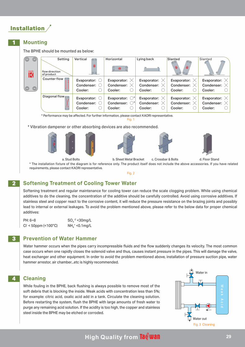
* The installation fixture of the diagram is for reference only. The product itself does not include the above accessories. If you have related requirements, please contact KAORI representative.
* Performance may be affected. For further information, please contact KAORI representative.
Installation
1
2
3
4
Mounting
Softening Treatment of Cooling Tower Water
Prevention of Water Hammer
Cleaning
The BPHE should be mounted as below:
Softening treatment and regular maintenance for cooling tower can reduce the scale clogging problem. While using chemical additives to do the cleaning, the concentration of the additive should be carefully controlled. Avoid using corrosive additives. If stainless steel and copper react to the corrosive content, it will reduce the pressure resistance on the brazing joints and possibly lead to internal or external leakages. To avoid the problem mentioned above, please refer to the below data for proper chemical additives:
Water hammer occurs when the pipes carry incompressible fluids and the flow suddenly changes its velocity. The most common case occurs when one rapidly closes the solenoid valve and thus, causes instant pressure in the pipes. This will damage the valve, heat exchanger and other equipment. In order to avoid the problem mentioned above, installation of pressure suction pipe, water hammer arrestor, air chamber...etc is highly recommended.
While fouling in the BPHE, back flushing is always possible to remove most of the soft debris that is blocking the inside. Weak acids with concentration less than 5%; for example: citric acid, oxalic acid add in a tank. Circulate the cleaning solution. Before restarting the system, flush the BPHE with large amounts of fresh water to purge any remaining acid solution. If the acidity is too high, the copper and stainless steel inside the BPHE may be etched or corroded.
Fig. 1
Fig. 2
a. Stud Bolts b. Sheet Metal Bracket c. Crossbar & Bolts d. Floor Stand
Fig. 3 Cleaning
* Vibration dampener or other absorbing devices are also recommended.
PH: 6~8 SO4-2 <30mg/L
Cl- < 50ppm (<100°C) NH4+ <0.1mg/L
We
ak
Ac
id
Water in
Water out
flow directionof product
Vertical Horizontal Lying back Slanted SlantedSetting
Counter flow
Diagonal flow
Evaporator: ○Condenser: ○Cooler: ○
Evaporator: ╳Condenser: ╳Cooler: ○
Evaporator: ╳Condenser: ╳Cooler: ○
Evaporator: ╳Condenser: ╳Cooler: ○
Evaporator: ╳Condenser: ╳Cooler: ○
Evaporator: ○Condenser: ○Cooler: ○
Evaporator: ○*Condenser: ○*Cooler: ○
Evaporator: ╳Condenser: ╳Cooler: ○
Evaporator: ╳Condenser: ╳Cooler: ○
Evaporator: ╳Condenser: ╳Cooler: ○
29

www.kaori-bphe.comKAORI reserves the right to make changes without prior notice. 2019.12/1,000
Professionals in Customized Heat Exchangers
HEAD OFFICENo. 5-2, Chi-Lin North Road, Chung-Li District, Taoyuan City 32062, Taiwan TEL: +886-3-4626958 FAX: +886-3-4628021E-Mail: [email protected]


