FEATURES AND OPTIONS ................................................................................................................................... 10
INSTALLATION OF ALUMINUM FRAMED CLOCKS .................................................................................... 12
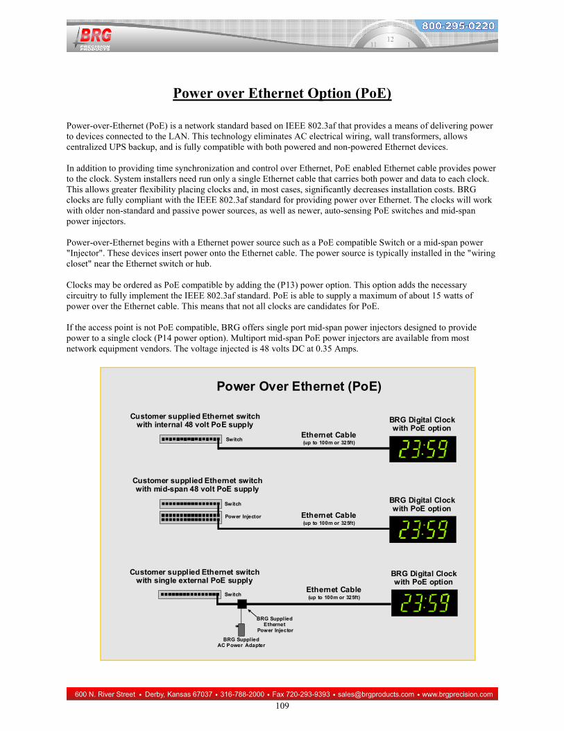
POWER OVER ETHERNET OPTION (POE) .................................................................................................... 109
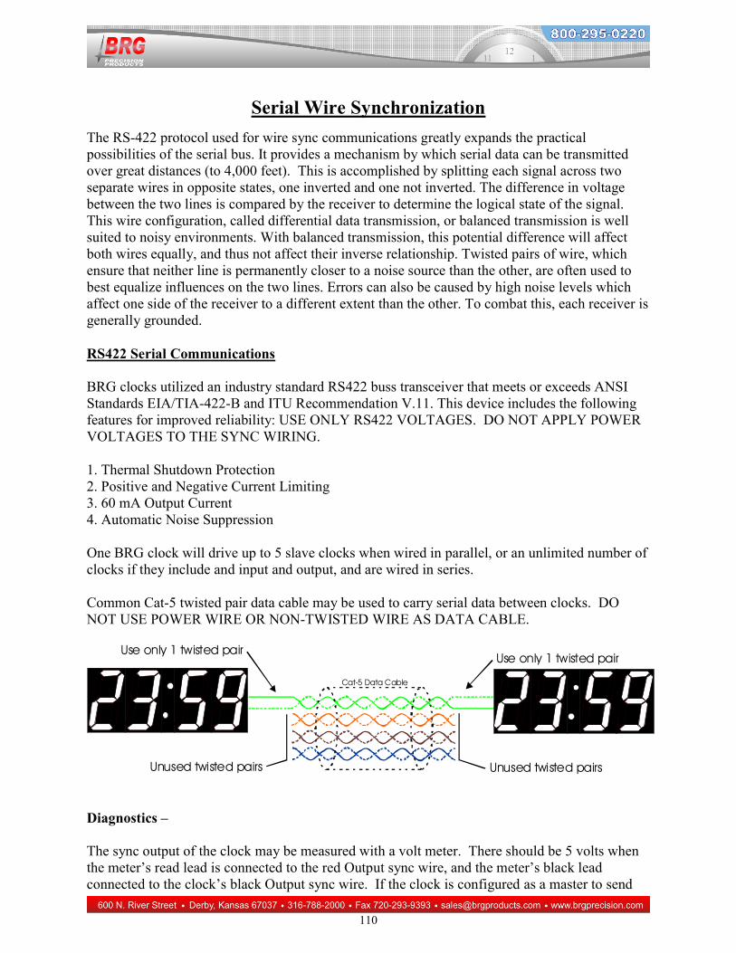
SERIAL WIRE SYNCHRONIZATION ............................................................................................................... 110
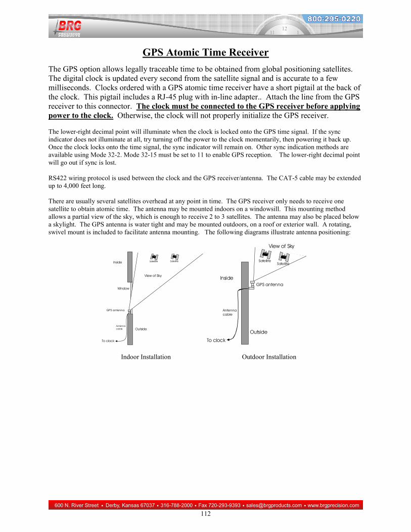
GPS ATOMIC TIME RECEIVER ........................................................................................................................ 112
PC / DIGITAL CLOCK CONTROL SOFTWARE ............................................................................................. 113
PC USB / RS422 ADAPTER ................................................................................................................................... 114
SERIAL SYNC COMMUNICATIONS PROTOCOL ......................................................................................... 115
BRG CLOCK SERIAL COMMAND STRUCTURE........................................................................................... 115
EXTERNAL CONTROL LINE WIRING DIAGRAM (CL OPTION) .............................................................. 122
INDEX ...................................................................................................................................................................... 123
3
Warranty Agreement
BRG Precision Products One Year Warranty 1. Term of Coverage Coverage will be for 1 year. Claims must be made during the Warranty Period. This Agreement is not renewable. The warranty becomes null and void if complete payment is not made within the terms specified under Terms of Payment. 2. Warranty BRG Precision Products, Inc. warrants the Product against defects in workmanship and materials during the Coverage Period. 3. Coverage BRG Precision Products, Inc. will, at its option, repair or replace the defective Product free of charge, provided that you notify BRG Precision Products, Inc. of the Product defect within the Coverage Period, and provided that BRG Precision Products, Inc. through inspection establishes the existence of such a defect and that it is covered by this Agreement. BRG Precision Products, Inc. will, at its option, use new and/or reconditioned parts in performing warranty repair and building replacement products. BRG Precision Products, Inc. reserves the right to use parts or products of original or improved design in the repair or replacement. If BRG Precision Products, Inc. repairs or replaces a Product, the warranty continues for the remaining portion of the Coverage Period without extension. All replaced Products and all parts removed from repaired Products become the property of BRG Precision Products, Inc. BRG Precision Products, Inc. covers both parts and labor necessary to repair the Product, and return shipment to the Customer via a BRG Precision Products, Inc.-selected non-expedited surface freight within the contiguous United States and Canada. Alaska and Hawaii return shipments to the Customer are via non-expedited air freight. 4. What Is Not Covered This Agreement does not cover costs related to the removal, installation, or field troubleshooting of the Product under the terms of the Agreement if, and not limited to: a) the Product has been misused, neglected, improperly installed, physically damaged or altered, either internally or externally, or damaged from improper use or use in an unsuitable environment; b) the Product has been subjected to fire, splashed water (unless specifically ordered to be water resistant), submersion into any liquid, generalized corrosion, biological infestations, or high input voltage including lighting strikes and generators operating outside the limits of their Product specifications; c) repairs have been done to it other than by BRG Precision Products, Inc. or its authorized service centers, or as assigned by BRG Precision Products; d) the Product is used as a component part of a Product expressly warranted by another manufacturer; e) the Product's original identification (trade-mark, serial number) markings have been defaced, altered, or removed; f) the Product is located outside of the United States and Canada; g) the customer has misrepresented the Product information provided to BRG Precision Products, Inc. in order to receive coverage under the terms of this Agreement. This Agreement does not warrant uninterrupted or error-free operation of the Product; h) Product malfunction or damage resulting from electromagnetic or solar radiation; i) Shipping charges to the factory more than 30 days after first receiving the product; j) Undesirable operation resulting from changes to public law after the product was purchased, such as changing the dates for daylight saving time. k) Normal wear and tear relating to the non-operating functions of the equipment such as discoloration from direct sunlight, heat, etc.
5. Disclaimer and Limitation of Liability TO THE EXTENT PERMITTED BY APPLICABLE LAW, OTHER THAN THE EXPRESS WARRANTY SET FORTH IN THIS AGREEMENT, BRG PRECISION PRODUCTS, INC. MAKES NO ADDITIONAL WARRANTIES, EXPRESS OR IMPLIED, AND DISCLAIMS ALL IMPLIED WARRANTIES, WHETHER IN
4
FACT OR BY OPERATION OF LAW, STATUTORY OR OTHERWISE, INCLUDING WARRANTIES OR CONDITIONS OF MERCHANTABILITY AND FITNESS FOR A PARTICULAR PURPOSE. ANY WARRANTIES THAT MAY NOT BE DISCLAIMED UNDER APPLICABLE LAW ARE LIMITED IN DURATION TO THE WARRANTY PERIOD. NO WARRANTIES, EXPRESS OR IMPLIED, WILL APPLY AFTER THIS PERIOD. IN NO EVENT WILL BRG PRECISION PRODUCTS, INC. BE LIABLE FOR ANY SPECIAL, INDIRECT, INCIDENTAL OR CONSEQUENTIAL DAMAGES, LOSSES, COSTS OR EXPENSES HOWEVER ARISING WHETHER IN CONTRACT OR TORT INCLUDING WITHOUT RESTRICTION ANY ECONOMIC LOSSES OF ANY KIND, ANY LOSS OR DAMAGE TO PROPERTY, ANY PERSONAL INJURY, ANY DAMAGE OR INJURY ARISING FROM OR AS A RESULT OF MISUSE OR ABUSE, OR THE INCORRECT INSTALLATION, INTEGRATION OR OPERATION OF THE PRODUCT. SOME STATES DO NOT ALLOW THE EXCLUSION OR LIMITATION OF INCIDENTAL OR CONSEQUENTIAL DAMAGES SO THE ABOVE LIMITATION MAY NOT APPLY TO YOU. BRG Precision Products, Inc. neither assumes nor authorizes any other person to assume for it any other liability in connection with the repair or replacement of the Product. 6. Claim Limits Claims are limited to repair or replacement, or if in BRG Precision Products, Inc.'s discretion that is not possible to reimbursement up to the purchase price paid for the Product. In no event will BRG Precision Products, Inc.'s liability under this Agreement exceed the purchase price paid for the Product. 7. Cancellation You may cancel this Agreement by providing to BRG Precision Products, Inc. written notice of your wish to cancel.
8. Insurance This Agreement is not a contract of insurance.
9. Amendment and Waiver No amendment, supplement, consent or waiver, express or implied, to or of any provision of this Agreement will be effective unless in writing signed by the parties hereto and then only in the specific instance and for the specific purpose given. 10. Assignment The Customer may assign or transfer this Agreement provided BRG Precision Products, Inc. is advised by the Customer in writing of such assignment and the new system owner's information. 11. Governing Law This Agreement will be governed by and interpreted exclusively in accordance with the laws of the State of Kansas, without reference to provisions concerning conflicts of laws. The provisions of the United Nations Convention on Contracts for the Sale of Goods are hereby excluded. 12. Arbitration Any controversy or claim arising out of or relating to this Agreement, or the breach of it, shall be settled by arbitration in accordance with the relevant rules of the American Arbitration Association, and judgment on the award rendered by the arbitrator may be entered in any court having jurisdiction thereof. The place of arbitration shall be Wichita, Kansas, United States of America. There shall be one arbitrator. 13. Severability If any provision of this Agreement is found by any court or arbitrator to be invalid, illegal or unenforceable, the validity, legality and enforceability of the remaining provisions will not be affected thereby. 14. Entire Agreement This Agreement constitutes the entire contract between the parties concerning the subject matter of this Agreement and supersedes all marketing brochures and other expectations, understandings, communications, representations and agreements, whether verbal or written, between the parties. THIS AGREEMENT GIVES YOU SPECIFIC LEGAL RIGHTS AND YOU MAY ALSO HAVE OTHER RIGHTS WHICH VARY FROM STATE TO STATE.
5
Once a return authorization number is obtained, ship the products to: BRG Precision Products Attn: RA# xxxxxxx (where xxxxxxx is the authorization number provided) 600 N. River Derby, KS 67037 Optional Extended Warranty:
A two-year extended warranty is available. The extended warranty must me purchased before the end of the standard warranty. The two-year extended warranty costs 20% of the product purchase price. Optional Advanced Replacement Service (“Hot Swap”):
For critical applications, BRG Precision Products recommends purchasing a complete backup product. If a backup product is too expensive or the application is only semi-critical, BRG Precision Products recommends the optional Replacement Service ("Hot Swap") This service allows the customer to receive a replacement product right away to replace a defective product that is covered under warranty. BRG Precision Products will pay for ground shipping to send the replacement product. The customer is responsible for expedited shipping charges over the cost of ground shipping. The customer is responsible for shipping charges to return the defective product. The Replacement Service is only available for shipments to the U.S. and Canada. When the customer receives the replacement product, the defective product must be returned to the factory within 30 days. The invoice for the replacement product will then be voided; otherwise, the full invoice amount for the replacement product is due. This service is only available in conjunction with warranty repairs. This replacement service may be purchased for 10% of the products purchase price at the time of the initial purchase. The replacement service may also be purchased after the initial product purchase and before the standard warranty expires for 15% of the product purchase price. The term of this service ends when the warranty expires. This service may be repurchased for 10% of the product purchase price when a two-year extended warranty is purchased. The product replacement service is only available on selected models. 30 Day Return Policy:
No returns will be accepted without prior written authorization of BRG. Incorrect merchandise received will receive prompt re-shipment of correct items. Incorrect merchandise, other than custom items, may be returned, shipped prepaid, and will be exchanged on an equivalent basis. Merchandise, other than custom items, that cannot be used may be returned at a 25% restocking charge if items are shipped prepaid in the original boxes. Carrier is responsible for parts damaged in shipment. The customer should have driver sign for damaged carton on delivery receipt and make a claim with the freight company. Please insist that the carrier's representative conduct an inspection, and retain all packing materials for the inspector. Please report promptly for immediate follow-up on short shipments. No action arising from any sale by BRG may be brought by a customer more than one year after the date of shipment.
-------------------------------------------------------------------------------- Terms of Payment:
New accounts require prepayment. International orders require prepayment by Telegraphic Transfer (bank wire). For established customers, payment is due in full within 30 days from invoice date. Other payment methods include Visa, Mastercard, American Express, Discover, Novus (Domestic Only). Add 4% for ground shipping in the U.S. and Canada. Domestic shipping is prepaid for U.S. Government orders. Other shipping methods are available. All past due accounts will be subject to a finance charge of 1.5% per month. BRG may cancel or delay future deliveries if customer fails to make prompt payment or if customer's financial condition warrant such action in BRG's opinion. BRG is not responsible for delays. The customer will be contacted and given the choice of receiving a partial
6
shipment or waiting for the full shipment. The firmware license may be suspended, limiting functionality of the equipment, if payment is not received within 90 days.
BRG Precision Products reserves the right to change prices without prior notification. Prices do not include taxes and BRG reserves the right to arrange for insurance on all orders.
-------------------------------------------------------------------------------- The courts of Sedgwick County, Kansas will have exclusive jurisdiction and venue over any disputes arising from any sale by BRG and customer and Buyer consent to personal jurisdiction of the federal and state courts located in Sedgwick County, Kansas. If legal action is brought by BRG for the collection of any amount owed or due to any other dispute, the prevailing party will be entitled to recover its reasonable attorneys' fees and costs incurred. These items constitute the entire agreement between BRG and customer, regardless of any additional or conflicting terms on customer's purchase order or other documentation, which are objected to, or any prior discussions or usages of trade. All sales by BRG are made only on the terms and conditions contained herein.
BRG commercial digital clocks are specifically designed for applications where precision and reliability are of utmost importance. These clocks may be used as accurate stand-alone time displays, or they can be synchronized, so that all clocks display the same time. Further, by using NTP, GPS or an internal ultra-high precision oscillator, all clocks can display the same, accurate, time. Any combination of clock shape, style or size may be synchronized. These clocks are in use by many organizations where accurate, synchronized time is required. Each clock provides a variety of time zone and display formats, including UTC (Zulu) Time, Any World Time Zone, Half-hour time zones, Enable or Disable Daylight Savings Time, and selectable 12 or 24 hour display formats with digital intensity control. In addition to displaying real time, each clock includes up/down timers and counters. General Specifications:
Display Format: Over 64 User Selectable Display Formats Tiger Processor Operating Modes: 6 User Selectable Operation modes Real Time
Up Timer Down Timer Up Counter Down Counter Event Timer.
Environment: -32 degrees F to 120 Degrees F, Humidity: 0% to 95% non-condensing Battery Backup: 10 year Rechargeable Battery or Capacitor to maintain the time during loss of power Clock Accuracy: A variety of clock accuracy options are available. The least accurate is + or – 60 seconds per year at 70 degrees F (20 degrees C). The most accurate stand-alone clock is accurate to the second over 40 years. External synchronization such as GPS and NTP provide absolute accuracy for an indefinite period.
10
Features and Options The BRG Digital Clock offers flexibility and reliability for a wide variety of time display applications. These clocks perform flawlessly whether you need to simply display hours and minutes, or when you need a synchronized clock system, event counters, elapsed timers, time zone display, etc. Standard Features Available:
Ultra-reliable, red light emitting diode (L.E.D.) bar segment display Anti-glare lens allows viewing under most lighting conditions Quartz oscillator for high accuracy Time adjustment register to further increase accuracy 10 year rechargeable battery – uses one millionth of a watt in standby mode Blinking, Solid or No Colon between hours and minutes Digital Intensity Control – individual display or all displays Seconds smaller than hours/minutes for easy viewing in 8 digit display models 99 total alarm settings with 12 day-of-the-week variables 98 alarm schedule groups Alarm schedule activation by date range Variable duration for each alarm setting Variable pulsing for each alarm setting Display can be set to blink when alarm is active or as silent alarm Timer operations are maintained during a power outage. When the power is restored, the correct count will display. Timer with flashing warning alarm for speaking engagements Enable/Disable auto switching between daylight and standard time – includes world date table Up/Down Event Counter – range –9999 to 9999 with Start, End and alarm Counter auto-increment with adjustable increment amount and period Up/Down Elapse Timer – Days, Hours : Minutes : Seconds . Hundredths with Start, End and alarm Display optionally blinks when the alarm activated Rotating display formats, i.e. time > date or time > temperature Sunrise/Sunset Calculations Sidereal Time 7 segment numeric or 5x7 alpha-numeric displays Available Options:
Clock/Timer/Counter external control line Auto Brightness Option – This option enhances the standard digital brightness control Radio Synchronization GPS atomic time receiver option turns the digital clock into a perpetually accurate master clock Serial Wired Synchronization Option – All clocks display the same time. Clock operates as either Master or Slave. Serial line control and configuration Ethernet communications for configuration, control and synchronization NTP (Network Time Protocol) allows the clock to obtain the time directly from Government or local timer servers. IRIG-B/SMPTE/ESE wire sync receiver Infrared Remote Control Option provides full programming control Wired remote control option Electronic Alert Horn or internal beeper for alerting and timer applications Alarm Relay Output for alerting, timer and control applications Temperature Sensor – for indoor or outdoor applications Timer/Counter Change Start/Change End Shortcut Buttons to directly access Start/End values Digital Zone lettering Thumb Wheel Switch Direct Start/End and Miscellaneous Parameter Entry Ultra-bright displays Timer Indicator Lights Tripod Display Stand Ultra-high Precision Oscillators
11
Standard Display Modes :
Multiple clocks may be placed adjacent to one another to form a comprehensive display. For example, one clock could display hours/minutes/seconds while a second clock could display the month/day and four digit year. Not all of the following features are included on every clock. Some operating modes must be specifically requested. There is no extra charge for the following features. Hours: Minutes (4 or 8 digit display) Hours: Minutes Seconds (8 digit display) Hours: Minutes Seconds. Hundredths (8 digit display) Hours: Minutes Month/Day (8 digit display) Hours: Minutes + four digit year (8 digit display) Hours: Minutes + day of the year (8 digit display) Hours: Minutes Hours: Minutes - two zones (8 digit display) Hours. Decimal Minutes (4 or 8 digit display) Minutes: Seconds (4 or 8 digit display) Seconds - centered (4 or 8 digit display) Day of the year (4 or 8 digit display) Day of the year plus last digit of the year (4 or 8 digit displays) Julian date - 7 digits (8 digit display) Julian date - last four digits (4 or 8 digit display) Month/Day - Year (4 or 8 digit display) Up/Down Elapsed Time - Seconds - centered (4 or 8 digit display) Up/Down Elapsed Time - Hours: Minutes (4 or 8 digit display) Up/Down Elapsed Time - Minutes: Seconds (4 or 8 digit display) Up/Down Elapsed Time - Hours: Minutes :Seconds (8 digit display) Up/Down Elapsed Time - Hours: Minutes :Seconds. Hundredths (8 digit display) Up/Down Elapsed Time - Days (4 or 8 digit display) Up/Down Elapsed Time - Days Hours: Minutes (8 digit display) Warning time blinks display prior to final time Up/Down Event Counter - 9999 to 9999 (4 or 8 digit display) Rotating hours: min > Julian date Rotating hours: min > month/day > year Rotating hours: min > temperature F > temperature C Temperature F Temperature C Elapsed hours (-9999 to 9999) Elapsed hours (99 hours - in place of 23 hour elapsed time) Elapsed days (-9999 to 9999) Number of GPS Satellites being received plus data activity Digital intensity control (4 or 8 digit display) Blinking digits (4 or 8 digit display) Blinking or solid colon Blinking once per second display when alarm activated Variable rate blinking when alarm activated 12/24 hour display format PM indicator Sync reception indicator Alpha month with numeric day of the month Alpha day of the week Automatically dim display at nighttime Minute decimal point may indicate daytime or night time Display Sunrise time Display Sunset time
12
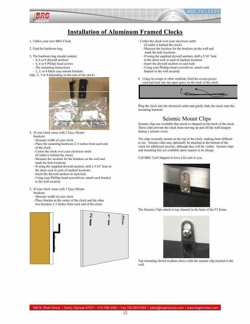
Installation of Aluminum Framed Clocks 1. Unbox your new BRG Clock. 2. Find the hardware bag. 3. The hardware bag should contain: - 4, 6 or 8 drywall anchors - 4, 6 or 8 Philips head screws - The mounting instructions - 2, 3, or 4 black easy-mount brackets. (Qty. 2, 3 or 4 depending on the size of the clock)
4. If your clock came with 2 Easy-Mount brackets: - Measure width of your clock. - Place the mounting hardware 2-3 inches from each end of the clock - Center the clock over your electrical outlet (if outlet is behind the clock) - Measure the location for the brackets on the wall and mark the hole locations - If using the supplied drywall anchors, drill a 5/16” hole in the sheet rock in each of marked locations - Insert the drywall anchors in each hole - Using your Phillips head screwdriver, attach each bracket to the wall securely 5. If your clock came with 3 Easy-Mount brackets: - Measure width of your clock - Place bracket in the center of the clock and the other two brackets 2-3 inches from each end of the clock
12 3
- Center the clock over your electrical outlet (if outlet is behind the clock) - Measure the location for the brackets on the wall and mark the hole locations - If using the supplied drywall anchors, drill a 5/16” hole in the sheet rock in each of marked locations - Insert the drywall anchors in each hole - Using your Phillips head screwdriver, attach each bracket to the wall securely 6. Using tie-wraps or other methods, bind the excess power cord and tuck into the open space on the back of the clock
Plug the clock into the electrical outlet and gently slide the clock onto the mounting brackets.
Seismic Mount Clips Seismic clips are available that attach to channel on the back of the clock. These clips prevent the clock from moving up and off the wall hangers during a seismic event. The clips normally mount on the top of the clock, making them difficult to see. Seismic clips may optionally be attached at the bottom of the clock for additional security, although they will be visible. Seismic clips and mounting kits are available upon request at no charge. Call BRG Tech Support to have a kit sent to you.
The Seismic Clips attach to top channel in the back of the F5 frame.
Top mounting shown in photo above with the seismic clip secured to the wall.
13
Operation
The BRG Digital Clock uses an L.E.D. display for reliable operation. The clock is protected against power failures with a rechargeable or Lithium battery. During the absence of power, the display is blanked to conserve the battery. All operating parameters are stored in non-volatile memory. The internal clock continues to operate from battery backup. When the A.C. power is restored, the clock resumes normal operation and display. If you have any questions or do not understand the operating modes listed below, please call technical support at 800-295-0220 before making any changes to the clock’s configuration. The PM indicator light (located in the upper left corner of the display) is used to indicate PM hours and sync status. When 12-hour display mode is used, the PM indicator will illuminate during PM hours. If enabled, the PM indicator will flicker at the top of every minute when the clock is in sync with a master clock. Changing the Time :
Press the Up button to advance the time, or the Down button to decrement the time. The longer you press the button, the faster the clock will move. Some models have these buttons temporarily disabled. Configuration Menu:
The Mode, Up, and Down buttons are used to select various operating modes and parameters. The values of the Mode, Up and Down buttons will change with increasing speed the longer the buttons are held down. Pressing the buttons quickly will quickly change the value. Some models have these buttons temporarily disabled. If the display blinks when the mode button is pressed, mode lockout has been enabled. Hold down the mode button until the blinking stops (about 5 seconds) then release. A “1” should appear meaning you have access to the menu system. The optional infrared or radio remote controls have equivalent buttons for each of the standard control buttons plus the change starting and ending time or count buttons. Please refer to the infrared remote instruction section for further explanation. Press the mode button to switch from real time display to mode selection. Mode number 1 will display (If the Day/Month displays instead of mode 1, press the mode button again.). Once Mode 1 displays, use the Up and Down buttons to move to the desired mode.
14
Press the Mode button again to enter a configuration mode. The Up and Down buttons are used to change modes and values. Press the Mode button again to exit the current mode. The mode change function will timeout and return to normal time display mode after 60 seconds of inactivity. To return to normal time display mode, Press the Timer Control Button, or change the mode number to zero, or allow the menu system to timeout.
15
Time Zone Clock Configuration In most cases, the time zone clock will be configured to your specifications. You may change this configuration at any time. For accurate time zone information, see http://www.timeanddate.com. If included, the optional infrared remote control is shipped attached to the back of the clock. Reference the infrared remote instruction section found later in this manual. The internal battery will maintain the time for 10-20 years. All operating parameters are maintained in flash memory which does not lose its’ memory when power is lost. When power is applied to the clock, all displays will illuminate and display the time(s) as configured. Changing operational parameters:
Mode 50-4: Zone Number Identifier – This mode is used to identify the zone number of each four digit display in clocks that use multiple four digit displays. 0=inactive (default), 1=displays the respective zone numbers of each display. Once the zone number is displayed, pressing either mode, up or down will return to normal display mode. Press the mode button and mode one will appear on the leftmost display. If the month/day appears, press mode again to return to the mode one display. Press the Up button until you reach Mode 20. Follow the steps below to configure Mode 20: Position Display Format - Set each display format using this mode. Display formats 2 or 3 are most common. See Mode 20 in the mode definition table for other display formats. Mode 21: Time Zone Offset from UTC - Set the time zone offset for each time source using this mode. Use 0 for Zulu or UTC time. Mode 22: Position Time Source- Set the time source for each display using this mode. The time source number usually matches the display number. There are 24 time sources and up to 24 four-digit displays. Mode 23: Position 12/24 Display Format - Set 12 or 24 hour display format for each zone using this mode. Mode 24: Position Daylight Savings Setting - Set auto switching for daylight savings time using this mode for each time source. The codes for various locations are: 0=disable daylight time 1=U.S., Canada, Bermuda 2=UK, Ireland, Scotland 3=Australia 4=Argentina 5=Israel 6=Brazil, etc. See Mode 24 in the mode definition table for other daylight savings codes. Also, daylight start and stop periods may be customized. Mode 33: Position Incremental Time Zone Offset –This mode optionally forces a 30 or 60 minute time advance for each respective zone. 0= no advance (default), 1=30 minute advance, 2=60 minute advance, 3=30 minute advance during daylight savings time only, 4=60 minute advance during daylight savings time only.
16
Time Zone Clock Configuration Examples Four zone display – from left to right, Pacific, Mountain, Central and Eastern time zones – 1. Mode 18 = 4 – set the number of zones 2. Mode 20-1 = 2 – set zone 1 display format to hours: minutes 3. Mode 20-2 = 2 – set zone 1 display format to hours: minutes 4. Mode 20-3 = 2 – set zone 1 display format to hours: minutes 5. Mode 20-4 = 2 – set zone 1 display format to hours: minutes 6. Mode 21-1 = -8 – set Pacific offset from UTC 7. Mode 21-2 = -7 – set Mountain offset from UTC 8. Mode 21-3 = -6 – set Central offset from UTC 9. Mode 21-4 = -5 – set Eastern offset from UTC 10. Mode 22-1 = 1 – point display position to the desired time source 11. Mode 22-2 = 2 – point display position to the desired time source 12. Mode 22-3 = 3 – point display position to the desired time source 13. Mode 22-4 = 4 – point display position to the desired time source 14. Mode 23-1 = 24 – set the display position to 24 hour display format 15. Mode 23-2 = 24 – set the display position to 24 hour display format 16. Mode 23-3 = 24 – set the display position to 24 hour display format 17. Mode 23-4 = 24 – set the display position to 24 hour display format 18. Mode 24-1 = 10 – set to U.S. daylight savings time 19. Mode 24-2 = 10 – set to U.S. daylight savings time 20. Mode 24-3 = 10 – set to U.S. daylight savings time 21. Mode 24-4 = 10 – set to U.S. daylight savings time
Two zone display with digital zone lettering – from left to right, display Pacific and Mountain time and then after a five seconds, display Central and Eastern time – the time zones and the zone lettering will cycle through two sets of zone locations 1. Mode 18 = 2 – set the number of physical zones 2. Mode 20-1 = 2 – set zone 1 display format to hours: minutes 3. Mode 20-2 = 2 – set zone 1 display format to hours: minutes 4. Mode 20-3 = 2 – set zone 1 display format to hours: minutes 5. Mode 20-4 = 2 – set zone 1 display format to hours: minutes 6. Mode 21-1 = -8 – set Pacific offset from UTC 7. Mode 21-2 = -7 – set Mountain offset from UTC 8. Mode 21-3 = -6 – set Central offset from UTC 9. Mode 21-4 = -5 – set Eastern offset from UTC 10. Mode 22-1 = 1 – point display position to the desired time source 11. Mode 22-2 = 2 – point display position to the desired time source 12. Mode 22-3 = 3 – point display position to the desired time source 13. Mode 22-4 = 4 – point display position to the desired time source 14. Mode 23-1 = 24 – set the display position to 24 hour display format 15. Mode 23-2 = 24 – set the display position to 24 hour display format 16. Mode 23-3 = 24 – set the display position to 24 hour display format 17. Mode 23-4 = 24 – set the display position to 24 hour display format 18. Mode 24-1 = 10 – set to U.S. daylight savings time 19. Mode 24-2 = 10 – set to U.S. daylight savings time 20. Mode 24-3 = 10 – set to U.S. daylight savings time 21. Mode 24-4 = 10 – set to U.S. daylight savings time 22. Mode 32-3 = 2 – Numeric display field multiplier 23. Mode 51-1 to 51-32 = enter 8 digital zone letters for each zone 24. Mode 52-2 = 16 – number of alpha digits installed 25. Mode 51-3 = 1 – frame rotating display 26. Mode 51-4 = 50 – set frame rotation speed in seconds (0-59) 27. Mode 51-4 = 50 – set frame rotation speed in seconds (0-59)
17
Up-Down Elapse Timer Configuration The BRG Tiger firmware supports short, medium and long duration timer operations. Short duration typically means less than 24 hours. This mode is used for short timing sequences and does not recover from a power loss. Medium duration timers may run as long as 9,999 days, but does not recover from a power loss. Long duration timers may cover many decades and does recover from a power loss. Timer operations are maintained during a loss of power. When the power is restored, the correct count will display (version 1.77 and later). The Up button starts, pauses and restarts the elapsed timer. The Down button pauses and resets the timer. Press the Up button to start the timer. Pressing the Up button again will pause the timer. Pressing the Up button a third time will start the time from the paused position. Pressing the Down button once will pause the timer. Pressing the Down button again will reset the timer. If your clock has serial sync wires, connect the red and black wires to the red and black wires of a master clock. Slave clocks receive sync pulses, while master clocks send pulses ten times per second. Slave clocks may be used for multiple displays of the same timer. If your clock is equipped with the optional infrared remote control, it is shipped attached to the back of the clock. Reference the infrared remote instruction section found later in this manual. The internal battery will maintain the time for about ten years. All operating parameters are maintained in flash memory which does not lose its’ memory when power is lost. Changing operational parameters:
The display is used to display and edit all operating modes and parameters. Press the mode button and mode one will appear on the display. If the month/day appears, press mode again to return to the mode one display. Press the Up button until you reach Mode 20. Follow the steps below to configure Press the Mode to exit to the previous level. Press the Down button until 0, which will exit to the previous level. Press Down again to mode to mode 14. Once at mode 14, press Mode to display the current operating mode. Using the Up or Down buttons, select mode 2 for up timer or mode 3 for down timer. Press the Mode button to exit back to the previous level. Press the Down button to move to 0, which will exit to normal display mode. Other modes: Mode 7: Beginning hours and minutes, or the value to appear when the Down button is pressed. Mode 8: Beginning seconds, or the value to appear when the Down button is pressed. Mode 9: Ending hours and minutes. The value is optionally used to activate a contact closure or to stop the timer. Mode 10: Ending seconds. The value is optionally used to activate a contact closure or to stop the timer. Mode 13: Stop Timer at End Time or continues when the End time is reached. Mode 20: Display Mode – set to various display formats as needed. Mode 26: Blinking Display – Display may be set to blink when the End time is reached. Mode 32-4: Code Blue Timer Control – stay in timer mode when the End time reached. Mode 32-5: Code Blue Timer Direction – up or down. Mode 32-6: External timer control line functionality. Mode 32-7: Resume real time after timer idle. Mode 32-10: Timer alarm – enable, disable. Mode 32-13: Alarm pulsing. Mode 32-17: Timer reverse direction at the end time Mode 32-18: Long Duration Timer mode Mode 34: Additional alarm pulsing. Mode 35: Medium Duration - Elapsed days or hours Reset value. Mode 36: Code Blue timer control display format
18
Mode 37-6: Elapsed days and hours functionality Mode 37-12: Turn off alarm when timer paused or reset Mode 32-24: Activate alarm relay when timer started Mode 32-22: Accelerated timer for motion picture special effects Mode 32-26: Red/Yellow/Green light mode using two relays. Set Mode 43-1=2 Mode 37-9: Use leading edge to start and stop the timer, with variable delay before start will pause the timer Mode 37-19: Use Start button to Start, Stop and Reset the timer. May be used with Mode 37-9 Mode 37-38: Increase Short Duration timer accuracy Mode 44-1: Ending month and day. – Used with Mode 18 (auto timer restart). Mode 44-2: Ending year. – Use with Mode 18 (auto timer restart).
19
Timer Configuration Examples
The following timer configurations are provided as examples of typical elapsed timers. It is, by no means, intended to be all inclusive. There are many thousands of ways to configure timers. In timer mode, the Up button becomes Start/Pause/Resume, and the Down button becomes Stop/Reset. There is an optional timer control line available for specialized timer applications. Modes 20 and above have two menu levels. Timer operations are maintained during a loss of power. When the power is restored, the correct count will display (version 1.77 and later). Simple Timer Button Control Operation – Mode 32-22 0=disable (default) 1=enable This mode activates the simple timer button control operation. When enabled, pressing the TC button will cycle through the display zones. Press the TC button once to select the first zone, causing the zone to blink. Once a zone is blinking, the Up and Down buttons may be used to change the value of that zone. Pressing and holding the Up or Down buttons will cause the value to change faster after several seconds. Press the TC button again to move to the next zone. After the last zone is selected, the display will return to normal operation. The TC button may also be used to toggle between Up and Down timer operation. During normal display operation, press and hold the TC button for about 4 seconds. Once zone 1 display blinks, release the TC button to toggle the timer operation. To determine the timer direction, press the Up button to determine if the timer is in the Up or Down direction. The simple timer button operation supports display modes 1, 2, 10, 12, 13, 21, 22 and 27. Setting Mode 13=1 will stop a countdown timer when 0 is reached. Setting Mode32-17=1 will cause a down timer to reverse direction at 0.
Up timer starting at zero. No upper time limit. Display minutes and seconds only on a four digit display. 1. Mode 23-1=24 – set the display to 24 hour format 2. Mode 7=0:00 – reset to zero 3. Mode 13=0 – allow the timer to pass through the end time, which defaults to 0:00 4. Mode 14=2 – set up timer direction 5. Mode 20-1=12 – configure the display to show minutes and seconds Hospital Code Blue or Operating Room timer with four digit display. Normally display real time hours, minutes and seconds. An ordinary light switch with red wall plate is recommended to control the timer. When the code blue switch is turned on, the display will immediately switch to up timer mode, reset the timer, start counting up from zero. Turning the timer switch off will pause the timer for the number of minutes specified in Mode 32-7. At the conclusion of the pause delay, the timer will return to real time display. Mode 23-1=24 – set the real time display to 24 hour format (optional) Mode 32-4=2 – stay in timer mode until pause timeout Mode 32-5=0 – set timer direction to up direction Mode 32-6=1 – timer will run as long as timer switch is on Mode 32-7=30 – stay in timer mode for 30 minutes after timer is stopped, then return to real time display Mode 36-1=12 – set timer display format to minutes and seconds
20
Hospital Code Blue or Operating Room timer with six digit display. Normally display real time hours, minutes and seconds. An ordinary light switch with red wall plate is recommended to control the timer. When the code blue switch is turned on, the display will immediately switch to up timer mode, reset the timer, start counting up from zero. Turning the timer switch off will pause the timer for the number of minutes specified in Mode 32-7. At the conclusion of the pause delay, the timer will return to real time display. Mode 23-1=24 – set the real time display to 24 hour format (optional) Mode 32-4=2 – stay in timer mode until pause timeout Mode 32-5=0 – set timer to up direction Mode 32-6=1 – The timer will run as long at the Timer Control line is closed. When the timer control line is opened, the timer will pause for the duration specified by Mode 32-7. Once the pause delay has concluded, the timer will return to a real time display. Mode 32-7=10 – stay in timer mode for 10 minutes after timer is stopped, then return to real time display Mode 36-1=46 – set timer display format to minutes and seconds Mode 36-2=48 – set timer display format to minutes and seconds
Hospital Code Blue timer with four digit display. Normally display real time hours and minutes. When the code blue button is pressed or code blue line is turned on, switch to up timer mode, set the display to minutes and seconds, reset the timer, start counting up from zero. Pressing the code blue button again will have no effect until the timer is reset back to real time. Press the reset button once to stop the timer. Pressing the reset button again will have no effect, unless it is held down for more than five seconds, at which time it will return to real time display. The display will remain frozen for 30 minutes. After that, it will automatically return to real time display. Mode 23-1=24 – set the display to 24 hour format Mode 13=0 – allow the timer to pass through the end time, which defaults to 0:00 Mode 32-4=2 – stay in timer mode until pause timeout Mode 32-5=0 – set timer to up direction Mode 32-6=3 – code blue button will start the timer. Further presses will have no effect until the timer is reset back to real time. Mode 32-7=30 – stay in timer mode for 30 minutes after timer is stopped, then return to real time display Mode 36-1=12 – set timer display format to minutes and seconds Mode 37-10=3 - holding down the reset button for 5 sec or more returns the timer to real time
Up timer starting at zero. Stop the timer at ten minutes and sound the alert horn for five seconds. Display hours and minutes on a four digit display with blinking colon while timer is running. 1. Mode 23-1=24 – display to 24 hour format 2. Mode 5=5 – set alarm duration to 5 seconds 3. Mode 7=0:00 – reset to zero 4. Mode 9=0:10 – end time to 10 minutes 5. Mode 13=1 – stop timer at the end time 6. Mode 14=2 – set up timer direction 7. Mode 20-1=3 – display hours and minutes with blinking colon
21
Up timer starting at zero. Stop the timer at 10 minutes and sound the alert horn for five seconds. Display hours and minutes on a four digit display with blinking colon while timer is running. 1. Mode 23-1=24 – display to 24 hour format 2. Mode 5=5 – set alarm duration to 5 seconds 3. Mode 7=0:00 – reset to zero 4. Mode 9=0:10 – end time to 10 minutes 5. Mode 13=1 – stop timer at the end time 6. Mode 14=2 – set up timer direction 7. Mode 20-1=3 – display hours and minutes with blinking colon Up timer using only the Start button to start, stop and reset the timer. Start at zero and count up. After the timer has ran for five seconds, allow the Start button to stop the timer. When the timer is stopped, the start button will reset the timer and start it running again. Display minutes and seconds only. 1. Mode 13=0 – Do not stop the timer at the end time. 2. Mode 20-1=12 – Display minutes and seconds 3. Mode 37-9=5 – Use the leading edge to start and stop the timer. Wait five seconds before allow the start button
to stop the timer. 4. Mode 37-19=1 – When the timer is stopped, pressing the Start button will reset the timer and start it running. Elapsed days since last accident or incident on a four digit display. Up timer starting at 12:00, July 10, 2000. This assumes the starting date is older than the current date. 1. Mode 9=12:00 – set starting hour and minutes 2. Mode 32-18=1 – enable auto timer restart after power failure 3. Mode 44-1=07/10 - starting month and day 4. Mode 44-2=2000 - starting year Elapsed days, hours, minutes and seconds since last accident or incident using a twelve digit display. Up timer starting at 12:00, July 10, 2000. This assumes the starting date is older than the current date. 1. Set the current time using the up and/or down buttons 2. Mode 1 – set the current month and day 3. Mode 2 – set the current year 4. Mode 18=3 – number of four digit displays 5. Mode 37-34=21 – display elapsed days on first display (default) 6. Mode 37-35=2 – display hours and minutes (default) 7. Mode 37-36=1 – display seconds on third display 8. Mode 32-18=1 – enable auto timer restart after power failure 9. Mode 44-1=07/10 - starting month and day 10. Mode 44-2=2000 - starting year 11. Mode 9=12:00 – starting hour and minutes Down timer starting at the 22:00 00, July 4, 2000, and counting down to 00:00 00, January 1, 2001. Display elapsed days, hours, minutes, seconds and hundredths on a twelve digit display. Flash the display for ten seconds when the timer passes through the end of the
22
year, then reverse timer direction and begin up timer operation. Enable the auto-restart feature to automatically restart the timer in the event of a power failure. 1. Set the current time (22:00) using the up and down buttons 2. Mode 1=set the current month and day (07/04) 3. Mode 2=set the current year (2000) 4. Mode 5=10 – set alarm duration to 10 seconds – this also controls the length of time to flash the display 5. Mode 9=00:00 – set ending hours and minutes 6. Mode 10=00 – set the end seconds (default) 7. Mode 37-34=21 – display days elapsed on the leftmost four digits (default) 8. Mode 37-35=2 – display hours and minutes on the center four digits (default) 9. Mode 37-36=11 – display seconds and hundredths on the rightmost four digits 10. Mode 26-1=4 – flash the display full on and off at a rate determined by the alarm pulse rate (mode 32-13) 11. Mode 32-13=10 – flash the display at a rate of ten times per second 12. Mode 32-17=1 – reverse timer direction when the end time is reached 13. Mode 32-18=1 – enable auto timer restart after power failure 14. Mode 44-1=00/00 - ending month and day 15. Mode 44-2=2001 - ending year Down timer starting at 10:20 15. Stop at zero and sound the alert horn for 5 seconds. Display hours, minutes and seconds using an eight digit display. 1. Mode 23-1=24 – display to 24 hour format 2. Mode 5=5 – set alarm duration to 5 seconds 3. Mode 7=10:20 – set Starting hours and minutes 4. Mode 8=15 – set Starting seconds 5. Mode 13=1 – stop at the end time 6. Mode 14=3 – set down timer direction 7. Mode 20-1=2 – display hours and minutes on the leftmost four digits 8. Mode 20-2=1 – display seconds on the rightmost four digits Down timer starting at 0:30 00. Stop at zero and sound the alert horn for 5 seconds. Blink the display rapidly one minute before the timer stops. Display hours, minutes and seconds using an eight digit display. 9. Mode 23-1=24 – display to 24 hour format 10. Mode 5=5 – set alarm duration to 5 seconds 11. Mode 7=10:20 – set Starting hours and minutes 12. Mode 8=15 – set Starting seconds 13. Mode 13=1 – stop at the end time 14. Mode 14=3 – set down timer direction 15. Mode 20-1=2 – display hours and minutes on the leftmost four digits 16. Mode 20-2=1 – display seconds on the rightmost four digits 17. Mode 43-1=3 – Warning time enabled, disable relay output 18. Mode 43-2=0:01 – Set warning time one minute before stop time 19. Mode 43-4=5 – Blink the display for five seconds 20. Mode 43-5=20 – Blink the display twenty times per second Down timer starting at ten minutes and counting down to zero, then stopping. Flash the display for five seconds when the timer stops. Display minutes and seconds on a four digit display. 1. Mode 23-1=24 – display to 24 hour format 2. Mode 5=5 – set alarm duration to 5 seconds – this also controls the length of time to flash the display 3. Mode 7=0:10 – set Starting hours and minutes 4. Mode 13=1 – stop at the end time
23
5. Mode 14=3 – set down timer direction 6. Mode 20-1=12 – display minutes and seconds 7. Mode 26-1=4 – flash the display full on and off at a rate determined by the alarm pulse rate (mode 32-13) 8. Mode 32-13=10 – flash the display at a rate of ten times per second Down timer starting at 30 seconds and counting down to zero, then stopping. Close the alarm relay while the timer is running. Use either the timer control button or the start button to start timer. Use the Change Start/Change End buttons to change the Starting time. Display seconds only, centered on the display. 1. Mode 8=30 – timer Start equals 30 seconds 2. Mode 14=3 – set operating mode to count down timer 3. Mode 32-4=2 – stay in timer mode when the end time is reached 4. Mode 32-5=1 – set code blue timer direction to down timer 5. Mode 32-24=1 – activate relay when timer starts 6. Mode 32-26=1 – enable warning relay 7. Mode 37-12=1- turn off relay when timer stops 8. Mode 37-14=3 – enable Change Start/Change End buttons Color Signal Light (Green/Yellow/Red) indicator with down timer starting at 1:30 seconds and counting down to zero, then stopping. When the timer is started, the red light goes out and the green light illuminates. When the timer gets down to 1 minute, the green light goes out and the yellow light illuminates. When the timer is stopped or paused, the red light illuminates. 1. Mode 7=0:01 – timer Starting hours and minutes 2. Mode 8=30 – timer Starting seconds 3. Mode 14=3 – set to down timer mode 4. Mode 20-1=12 – display minutes and seconds 5. Mode 32-26=2 – enable three light operation 6. Mode 43-1=4 – enable optional secondary channel for warning light 7. Mode 43-3=30 – timer warning alarm seconds (yellow light enabled) Numeric Display using a color changing numeric display (Green/Yellow/Red/Blue) with down timer starting at 1:30 seconds and counting down to zero, then stopping. When the timer is started, the red light goes out and the green light illuminates. When the timer gets down to 1 minute, the green light goes out and the yellow light illuminates. When the timer is stopped or paused, the red light illuminates. 1. Mode 7=0:01 – timer Starting hours and minutes 2. Mode 8=30 – timer Starting seconds 3. Mode 14=3 – set to down timer mode 4. Mode 20-1=12 – display minutes and seconds 5. Mode 32-26=2 – enable three light operation 6. Mode 43-1=4 – enable optional secondary channel for warning light 7. Mode 43-3=30 – timer warning alarm seconds (yellow light enabled) 8. Mode 32-82=1 – Change numeric display color in place of a signal light
24
Expanded function Numeric Display using a color changing numeric display (Green/Yellow/Red/Blue) with down timer starting at 1:30 seconds and counting down to zero, then stopping. When the timer is started, the display changes from red to green. When the timer gets down to 1 minute, the display changes from green to yellow. When the timer is stopped or paused, the display changes to red. To switch from timer to real time, stop the timer by pressing the Up or Down buttons. Then press the timer control (TC) button. When the timer returns to real time, the display changes to blue.
1. Mode 20-1=2 – display hours and minutes in real time mode 2. Mode 32-4=2 – press timer control button to change from real time to timer and start the timer running 3. Mode 32-5=1 – start the timer in the down direction 4. Mode 36-1=12 – display minutes and seconds in timer mode 5. Mode 32-17=1 - enable timer auto reverse 6. Mode 32-26=2- enable timer signal lights 7. Mode 32-82=1 - use display to indicate timer color 8. Mode 32-37=1 - the timer control button (TC) switches to real time when timer is stopped 9. Mode 7=00:01 – timer start hours and minutes 10. Mode 8=30 – timer start seconds 11. Mode 43-1=4 – warning time operating mode 12. Mode 43-2 =00:01 – warning alarm hours and minutes 13. Mode 6=3 – set the display color to blue while in real time mode 14. Mode 37-38=1 – high precision mode 15. Mode 5=0 – alarm relay duration
Color changing class pass countdown timer that changes color using a 4 digit numeric display:
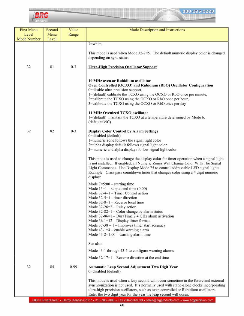
1. Mode 7=0:05 – starting hours:minutes 2. Mode 13=1 – stop at end time (0:00) 3. Mode 32-4=1 – Timer Control action 4. Mode 32-5=1 - timer direction 5. Mode 32-8=1 – Receive local time 6. Mode 32-26=2 – Relay action 7. Mode 32-82=1 – Color change by alarm status 8. Mode 32-86=1 – DuraTime 2.4 GHz alarm activation (or Wi-Fi) 9. Mode 36-1=12 – Display timer format 10. Mode 37-38 = 1 – Improves timer start accuracy 11. Mode 43-1=4 – enable warning alarm 12. Mode 43-2=0:01 – warning alarm time
Digital Audio Alarm using 4 digit countdown timer. Timer displays seconds and hundredths and real time displays hours and minutes. Pressing the Up or Down buttons immediately cancels audio play.
1. Mode 8=5 – Starting time is 5 seconds 2. Mode 13=1 – stop at the end time (0:00) 3. Mode 14=3 – start timer in the down direction 4. Mode 20-1=2 – display hours and minutes in real time 5. Mode 32-4=2 – The blue timer control button changes real time to timer, resets the timer, and starts the
countdown 6. Mode 32-5=1 – Start the timer in the down direction 7. Mode 36-1=11 – display seconds and hundredths in timer mode 8. Mode 37-84=15 – set the digital audio player to full volume
25
9. Mode 37-85=48 – select a 5 second audio recording Digital Audio Alarm using 4 digit countdown timer. Repeat audio selection Timer displays minutes and seconds and real time displays hours and minutes. Pressing the Up or Down buttons immediately cancels audio play.
1. Mode 8=5 – Starting time is 5 seconds 2. Mode 13=1 – stop at the end time (0:00) 3. Mode 14=3 – start timer in the down direction 4. Mode 20-1=2 – display hours and minutes in real time 5. Mode 32-4=2 – The blue timer control button changes real time to timer, resets the timer, and starts the
countdown 6. Mode 32-5=1 – Start the timer in the down direction 7. Mode 36-1=12 – display seconds and hundredths in timer mode 8. Mode 37-84=15 – set the digital audio player to full volume 9. Mode 37-85=48 – select a 5 second audio recording 10. Mode 37-87=5 – play the selected audio for 5 seconds 11. Mode 37-88=4 – repeat playing the selected audio 4 times 12. Mode 5=0 – alarm relay duration
Master / Slave Timer with MP3 audio alarm and display color changes. Down timer starting at 30 seconds and counting down to zero, then stopping. Close the alarm relay while the timer is running. Use either the timer control button or the start button to start timer. Use the Change Start/Change End buttons to change the Starting time. Display seconds only, centered on the display. Master clock configuration
1. Mode 8=30 – timer Start equals 30 seconds 2. Mode 14=3 – set operating mode to count down timer 3. Mode 32-4=2 – stay in timer mode when the end time is reached 4. Mode 32-5=1 – set code blue timer direction to down timer 5. Mode 32-24=1 – activate relay when timer starts 6. Mode 32-26=1 – enable warning relay 7. Mode 37-12=1- turn off relay when timer stops 8. Mode 37-14=3 – enable Change Start/Change End buttons 9. Mode 32-11=1 – enable operating mode and display format switching
Slave clock configuration
1. Mode 32-11=1 – enable operating mode and display format switching 2. Mode 32-16 =1 – alarm master/slave control
26
Master Slave / Timer. Down timer starting at 50 minutes and counting down to zero, then stopping. Close the relay for three seconds after stopping. Use the Timer Control button to start timer. Use the Change Start/Change End buttons to change the Starting time. Display minutes and seconds while in timer mode. Master clock configuration
1. Mode 7=0:50 or 12:50 – timer Start equals 30 seconds – change as needed 2. Mode 13=1 – Stop timer at 0:00 3. Mode 32-4=2 – stay in timer mode when the end time is reached 4. Mode 32-5=1 – set code blue timer direction to down timer 5. Mode 32-11=1 – enable operating mode and display format switching 6. Mode 32-24=1 – activate relay when timer starts 7. Mode 32-26=1 – enable warning relay – optional 8. Mode 36-1=12 – timer minutes : second format 9. Mode 37-12=1- turn off relay when timer stops - optional 10. Mode 37-14=3 – enable Change Start/Change End buttons 11. Mode 37-31=1 – TC switches to real time when timer is stopped
Slave clock configuration
1. Mode 32-11=1 – enable operating mode and display format switching 2. Mode 32-16 =1 – alarm master/slave control
Elapse time using a constant contact closure to display seconds and hundredths using a four digit display. Reset and Start the timer counting up and continue counting as long as the Timer Control line is closed. When the Timer Control line opens, the timer will stop. The reset button can also be used to reset the timer. Use display 54 if minutes and seconds, or hours and minutes are needed
1. Mode 20-1=11 – Display mode seconds and hundredths 2. Mode 32-4=2 – Use the timer control line to operate the timer 3. Mode 32-6=1 – Use constant contact closure to reset and start the timer 4. Mode 36-1=11 – Display mode seconds and hundredths 5. Mode 37-38=1 – For greatest precision when display hundredths of a second
27
Other Configuration Examples
Sync status color changing display. When the clock has sync’s with Ethernet, Wi-Fi, IRIG-B or GPS, the display will be green. If the clock loses sync for a period of time, the display will turn red.
1. Mode 6=1 – Set the display green when clock is sync’d 2. Mode 32-80=2 – Set the display red when the clock has lost sync 3. Mode 32-2=5 – enable display color sync indicator
Change display intensity or display color depending daytime/nighttime. Mode 32-35=1 – Reduce display intensity at night time Or Mode 32-35=3 – Change display color depending daytime/nighttime. . The default zone color will be used to indicate daytime. See also Mode 32-36, Modes 61,62,63,64 and Display Modes 56, 57, 58 and 59.
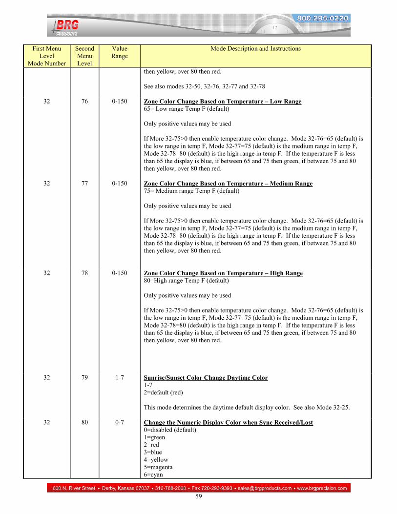
Numeric display color change based on temperature sensor Mode 32-75=0 = disabled (default) , 1=enabled Mode 32 -76 - low range in temp F Mode 32-77 – medium range in temp F Mode 32-78 - high range in temp F If More 32 -75 > 0 Then enable temperature color change. Mode 32 -76 = 65(default) is the low range in temp F, Mode 32-77=75 (default) is the medium range in temp F, Mode 32-78=80 (default) is the high range in temp F. If the temperature F is less than 65 the display is blue, if between 65 and 75 then green, if between 75 and 80 then yellow, over 80 then red. Temperature sensor hardware must be installed and enabled.
28
New Year’s Timer Operation: Requires firmware version 3.48 or later The timer will display real time hrs:min:sec On 12/31/2019 at 22:59:59, the display will switch from real time to down timer mode. The down timer will start at 1:00:00 and countdown to 00:00:00. At 00:00:10, the display will blink during the last ten seconds. When the timer stops at 00:00:00, the display will change to display the year (2020). To return the display to real time, cycle power to the display. The alarm relay will close for 1 second if installed. To test the display, set the date to 12/31/2019. Then set Modes 7=12:00 am, 8=20, 27-1=11:59 pm and 28-1=40. Exit the menu system and run the real time forward to 11:59 pm. The display will switch from real time to countdown timer at 11:59:40 pm and countdown starting at 00:00:20. At 00:00:10 the display will blink until it stops at 00:00:00. At this time, the display will switch to 2020. To restore the display, set Modes 7=1:00, 8=0, 20-1=46, 20-2=48, 27-1=10:59 pm, 28-1=59. Or, restore the original display configuration by restoring customer defaults. The following configuration can also be used with four digital displays by changing the display types to: 20-1=2 and 36-1=54. Modes:
5=1 7=1:00 am Timer Starting hours / minutes 9=0:00 Timer end hours / minutes 13=1 Stop timer at end time 20-1=46 (change for other display types) 20-2=48 (change for other display types) 26-1=2 Enable dim blinking 26-2=2 Enable dim blinking 27-1=10:59 pm Alarm hour/minute 28-1=59 Alarm second 29-1=8 Alarm day of the week 32-4=2 Stay in timer mode at end time 32-5=1 Timer down direction 32-13=5 Pulse alarm output 32-37=1 Return to real time from timer 32-45=71 Timer to real time display format
34-1=99 Activate timer by alarm schedule 36-1=46 (change for other display types) 36-2=48 (change for other display types) 37-1=0 Use alarm schedule date range 37-8=1 Auto-restart timer 43-1=3 Warning alarm 43-3=10 Warning alarm seconds 43-4=10 Warning alarm duration 43-5=1 Warning alarm blink rate 44-1=12/31 Target month and day 44-2=2019 Target year (2050=every year)
29
Up-Down Counter Configuration Your counter/clock has been configured to your specifications. You may change this configuration at any time. If your clock has serial sync wires, connect the red and black wires to the red and black wires of a master clock. Slave clocks receive sync pulses, while master clocks send pulses every second. If equipped with an external control wire option, the wiring diagram for the breakout box can be found later in this manual. These wires may be attached to normally open dry contact closures for remote operation. If your clock is equipped with the optional infrared remote control, it is shipped attached to the back of the clock. Reference the infrared remote instruction section found later in this manual. The internal battery will maintain the time for about ten years. All operating parameters are maintained in flash memory which does not lose its’ memory when power is lost. When power is applied to the clock, all displays will illuminate and display the time(s) as configured. Changing operational parameters:
The display is used to display and edit all operating modes and parameters. Press the mode button and mode one will appear on the display. If the month/day appears, press mode again to return to the mode one display. Press the Up button until you reach Mode 14. Once at mode 14, press Mode to display the current operating mode. Using the Up or Down buttons, select mode 4 for up count, or mode 5 for down count. Press the Mode button to exit back to the previous level. Press the Down button to move to 0, which will exit to normal display mode. The last count is saved to non-volatile memory if power is lost. Display Mode is automatically set when in counter mode. Counter Increment Button Debounce – 0-9999 – button delay in milliseconds Other applicable modes:
Mode 11: Start count, or the value to appear when the Down button is pressed. – Mode 12: End count. The value is optionally used to activate a contact closure or to stop the counter. Mode 13: Stop counter at the End count or continue when the End count is reached. If at End and Start=0, then Mode 13=0 Mode 26: Blinking Display – Display may be set to blink when End count is reached. – Mode 32-13: Alarm pulsing Mode 34: Additional alarm pulsing Mode 45-1: Auto-increment count –– 0-9999 Mode 45-2: Auto-increment rate value– 0-9999 (Mode 37-13 determines the rate) Mode 37-13: Auto-increment rate period –– 0=tenths of second, 1=second, 2=minutes, 3=hours Mode 45-4: Increment Amount– (default=1) – the counter will increase by this about for each counter increment
30
Counter Configuration Examples
Count up from zero using a four digit display. Pressing the Up button or momentarily closing the up line will increment the count. Pressing the timer control button or momentarily closing the code blue line will decrement the count. Pressing the Down button or momentarily closing the down line will reset the count. 1. Mode 14=4 – Set to up counter Display active production ‘goal’ and ‘actual’ count. This example uses 2 four digit displays. Both counters will start at zero at the beginning of the day. The ‘actual’ counter will increment each time a product is produced. The ‘goal’ counter will auto-increment so that the count at the end of the day will reflect the total goal for the day. The ‘actual’ count is configured the same as a simple counter. However, the ‘goal’ counter will be configured to automatically increment. Pressing the Up button will pause the ‘goal’ counter during lunch or other break periods. When the counter is paused, the letters, PAUS, will appear on the display. In this example, the goal counter will increment one count every 30 seconds. Actual counter: 1. Mode 14=4 – Set to up counter Goal counter: 1. Mode 14=4 – Set to up counter 2. Mode 37-13=1 – Increment amount in seconds (default) 3. Mode 45-1=1 – Amount to increment each period 4. Mode 45-2=30 – Increment every 30 seconds Display Days Without and Accident plus the Best Previous Record Days. The number of days without an accident is a long duration timer displaying days (zone 1). The best record days is a static display (zone 2). To set the month, day and year of the last accident press the Change Start button once to change the month and day. Press it again to change the year. Press it again to return to normal operation. To set the previous record display, press the Change End button. Press again to return to normal operation. The Timer Control button can be used to change the internal current time and date as needed. Requires firmware version 3.45 or later Mode 14=2 Mode 32-18=1 Mode 32-45=2 Mode 34-14=4 Mode 37-35=52
31
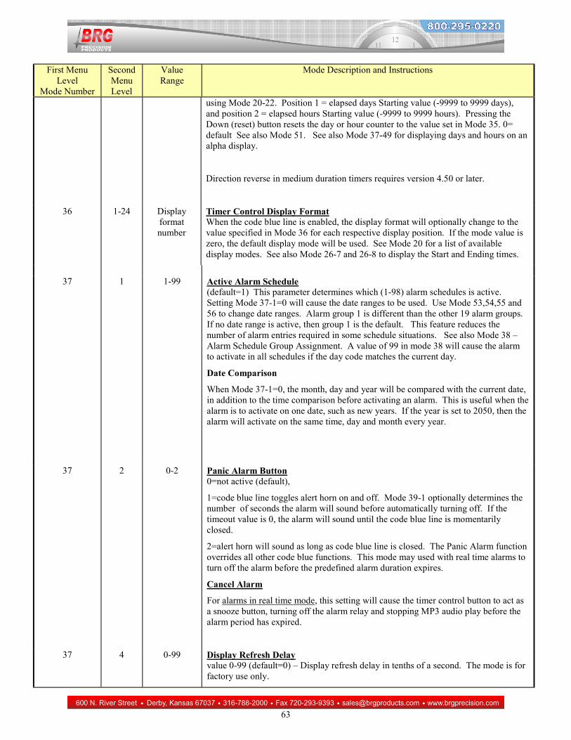
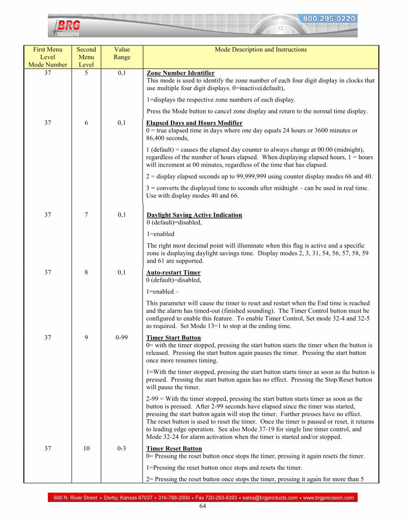
Alarm Configuration Each digital clock has 99 total alarm settings that can be configured to activate a relay, alert horn, or other device at various times and days. The duration of any single alarm can range from 1 to 99 seconds. Additionally, each alarm setting may be pulsed from 1 to 99 times per second. For example a start lunch break alert horn could sound a constant tone for three seconds beginning at 12:00 noon, Monday through Friday. The end of lunch tone could be pulsed twice per second, for three seconds of duration. The PC Control program for Windows is highly recommended for controlling alarm functions. This software is available for both two-wire serial, USB and Ethernet communications configurations. The clock must be ordered with one of these communications protocols in order to use the PC Control program. Use the Alarm Configuration Worksheet on the following page to organize your alarm settings. While your clock has been configured to your specifications, you may change this configuration at any time. If your clock has serial sync wires, connect the red and black wires to the red and black wires of a master clock. If your clock uses radio synchronization, a light will display to the lower right of the minutes when the clock is in sync with the master clock. The internal battery will maintain the time for about 10-20 years. All operating parameters are maintained in flash memory which does not lose its’ memory when power is lost. When power is applied to the clock, all displays will illuminate and display the time(s) as configured. When clocks are synchronized using serial wire sync, slave clocks incorporating an alert horn can be configured to follow the schedule of a single clock. This allows the alarm schedule in a single clock to control the alert horns of many clocks. Mode 32-16 enables and/or disables (default) this feature. Changing operational parameters The display is used to display and edit all operating modes and parameters. Applicable modes: Mode 27: Alarm Hours and Minutes. This field is required. Mode 28: Alarm Seconds. Use this to optionally set the alarm to the nearest second. Mode 29: Alarm Day Code. This field is required. Mode 5: Alarm Output Duration. Mode 30: Individual Alarm Output Duration. Mode 32-13: Alarm Pulse Control. Mode 32-16: Enable or Disable master/slave alarm function. 0=disabled (default), 1=enabled Mode 34: Individual Alarm Pulse Control. Mode 37-1: Active Alarm Schedule. This parameter determines which of the ten (0-98) alarm schedules is active. (Default=1) Mode 37-2: Panic Alarm using the optional Code Blue line. Mode 39-1: Panic Alarm duration Mode 38: Alarm schedule is assigned to each (1-99) specific alarm setting. (Default=0) Mode 53: Set beginning month/day in alarm schedule date range. Mode 54: Set ending month/day in alarm schedule date range. Mode 55: Set beginning year in alarm schedule date range. Mode 56: Set ending year in alarm schedule date range. Mode 59: Enable four-channel alarm output. Must also set Mode 32-26=2.
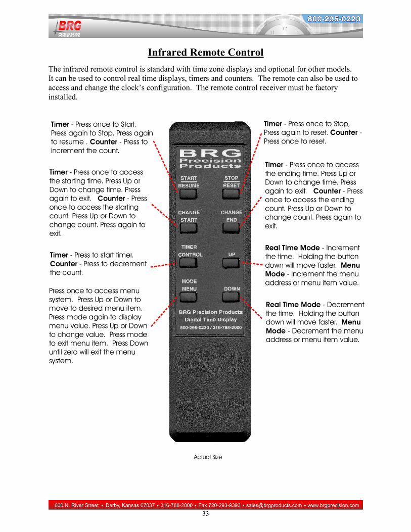
The infrared remote control is standard with time zone displays and optional for other models. It can be used to control real time displays, timers and counters. The remote can also be used to access and change the clock’s configuration. The remote control receiver must be factory installed.
34
Mega Processor Configuration Menu
General Menu Navigation:
Clock configuration is accomplished by editing parameters using a simple menu system. Only four buttons are used to navigate the menu. The Mode button enters the Menu. The Up and Down buttons move up and down through the menu items, and are used to change parameter values. The Timer Control button is used to save any changes and exit the menu system. Operation - Press and hold the Mode button to access the menu system. If the display blinks, then continue to hold the mode button until the blink stops. A “1” should then display. Using the Up and Down buttons, select the desired menu item. Press the Mode button again to display the parameter. For menu items above 19, press Mode again to access the menu’s second level. When a one appears, indicating the second level menu, press the Up or Down buttons to select the desired menu item, then press Mode to display the parameter value. Press the Up or Down buttons to change the parameter value. Once the parameter value is changed, press Mode to back out of the item and move to another item, or press the Timer Control button to save and exit the menu system. Pressing the Timer Control button at any time will save your changes and exit the menu system. Pressing the Mode button while a parameter value is displayed will back up one level. Press Up or Down to move to the next mode item. Pressing the Down button until mode 0 is reached will exit the menu system. Pressing the Timer Control button also exits the menu system. The menu will timeout and return to normal operation after 60 seconds in inactivity. If the display simply blinks when the Mode button is pressed, then the control buttons are locked out. See Mode 37-29 for more information about control button lockout. Not all of the following operating modes are included. Some operating modes must be specifically requested. A special operation menu is available for restoration and diagnostic purposes. Pressing and holding the mode button will cause either four blinking one’s or four blinking two’s to be displayed. Four one’s means no configuration has been stored in secondary memory. Four two’s means a previous configuration has been stored in secondary memory. Continuing to hold down the mode button allows shortcut menu operations. The one’s or two will disappear and the display will begin slowly counting up from 0. To execute a special command, release the Mode button while the selected command number is displayed. Then, immediately press the Timer control (TC) button for one second. The special commands are: 1=Software reset 2=Restore factory defaults, once the 2 appears, release the mode button and momentarily press the Timer Control button 3=Restore customer defaults from secondary memory (if previously stored) , once the 3 appears, release the mode button. Momentarily press the Timer Control button to confirm. 4=Store customer defaults in secondary memory, once the 4 appears, release the mode button. Momentarily press the Timer Control button to confirm.
35
6=Display zone numbers of a time zone display. For wireless master clock, enable transmitter test mode until clock is reset, blinks display 7=Illuminate all display segments, press up or down to cancel 8=Reset the BRG Ethernet interface web server user name and password to factory defaults. Momentarily press the Timer Control button to confirm. 9=Display the BRG Ethernet interface IP and MAC addresses (or momentarily press the Up and Down buttons at the same time) for clocks purchased after To unlock the buttons (if locked) and to display the BRG Ethernet interface IP address (if installed), momentarily press the Up and Down buttons at the same time. To force a display to use all alpha digits, press and hold the Timer Control button during power up. This will configure the display with 5 alpha digits allowing access to the menu.
First Menu Level
Mode Number
Second Menu Level
Value Range
Mode Description and Instructions
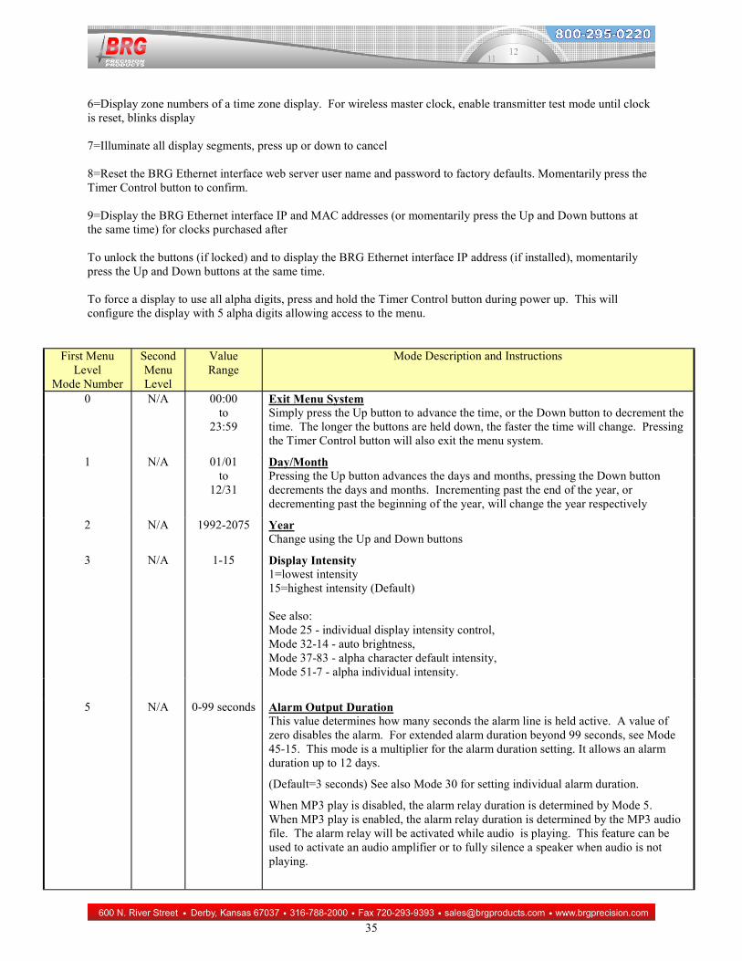
0 N/A 00:00 to
23:59
Exit Menu System Simply press the Up button to advance the time, or the Down button to decrement the time. The longer the buttons are held down, the faster the time will change. Pressing the Timer Control button will also exit the menu system.
1 N/A 01/01 to
12/31
Day/Month Pressing the Up button advances the days and months, pressing the Down button decrements the days and months. Incrementing past the end of the year, or decrementing past the beginning of the year, will change the year respectively
2 N/A 1992-2075 Year Change using the Up and Down buttons
5 N/A 0-99 seconds Alarm Output Duration This value determines how many seconds the alarm line is held active. A value of zero disables the alarm. For extended alarm duration beyond 99 seconds, see Mode 45-15. This mode is a multiplier for the alarm duration setting. It allows an alarm duration up to 12 days.
(Default=3 seconds) See also Mode 30 for setting individual alarm duration.
When MP3 play is disabled, the alarm relay duration is determined by Mode 5. When MP3 play is enabled, the alarm relay duration is determined by the MP3 audio file. The alarm relay will be activated while audio is playing. This feature can be used to activate an audio amplifier or to fully silence a speaker when audio is not playing.
36
First Menu Level
Mode Number
Second Menu Level
Value Range
Mode Description and Instructions
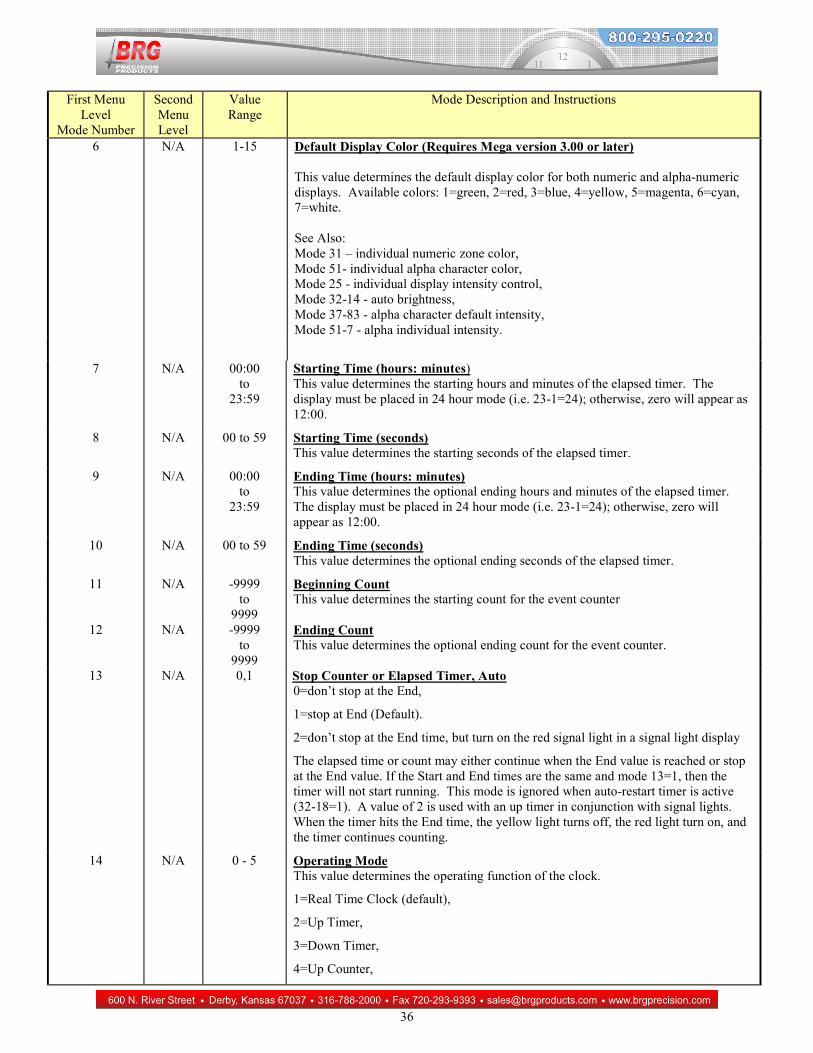
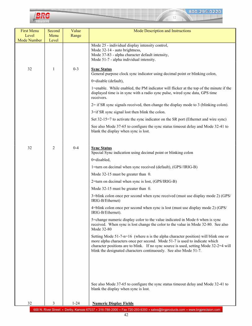
6 N/A 1-15 Default Display Color (Requires Mega version 3.00 or later) This value determines the default display color for both numeric and alpha-numeric displays. Available colors: 1=green, 2=red, 3=blue, 4=yellow, 5=magenta, 6=cyan, 7=white. See Also: Mode 31 – individual numeric zone color, Mode 51- individual alpha character color, Mode 25 - individual display intensity control, Mode 32-14 - auto brightness, Mode 37-83 - alpha character default intensity, Mode 51-7 - alpha individual intensity.
7 N/A 00:00 to
23:59
Starting Time (hours: minutes) This value determines the starting hours and minutes of the elapsed timer. The display must be placed in 24 hour mode (i.e. 23-1=24); otherwise, zero will appear as 12:00.
8 N/A 00 to 59 Starting Time (seconds) This value determines the starting seconds of the elapsed timer.
9 N/A 00:00 to
23:59
Ending Time (hours: minutes) This value determines the optional ending hours and minutes of the elapsed timer. The display must be placed in 24 hour mode (i.e. 23-1=24); otherwise, zero will appear as 12:00.
10 N/A 00 to 59 Ending Time (seconds) This value determines the optional ending seconds of the elapsed timer.
11 N/A -9999 to
9999
Beginning Count This value determines the starting count for the event counter
12 N/A -9999 to
9999
Ending Count This value determines the optional ending count for the event counter.
13 N/A 0,1 Stop Counter or Elapsed Timer, Auto 0=don’t stop at the End,
1=stop at End (Default).
2=don’t stop at the End time, but turn on the red signal light in a signal light display
The elapsed time or count may either continue when the End value is reached or stop at the End value. If the Start and End times are the same and mode 13=1, then the timer will not start running. This mode is ignored when auto-restart timer is active (32-18=1). A value of 2 is used with an up timer in conjunction with signal lights. When the timer hits the End time, the yellow light turns off, the red light turn on, and the timer continues counting.
14 N/A 0 - 5 Operating Mode This value determines the operating function of the clock.
1=Real Time Clock (default),
2=Up Timer,
3=Down Timer,
4=Up Counter,
37
First Menu Level
Mode Number
Second Menu Level
Value Range
Mode Description and Instructions
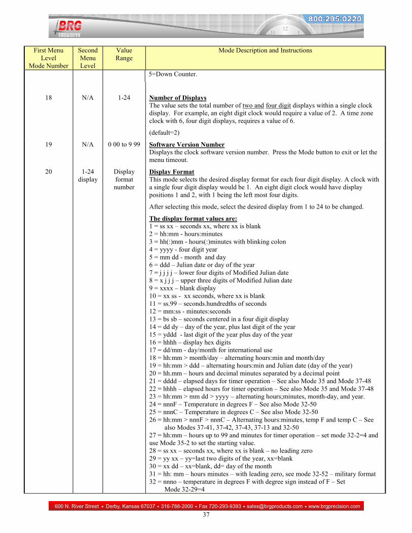
5=Down Counter.
18 N/A 1-24 Number of Displays The value sets the total number of two and four digit displays within a single clock display. For example, an eight digit clock would require a value of 2. A time zone clock with 6, four digit displays, requires a value of 6.
(default=2)
19 N/A 0 00 to 9 99 Software Version Number Displays the clock software version number. Press the Mode button to exit or let the menu timeout.
20 1-24 display
Display format number
Display Format This mode selects the desired display format for each four digit display. A clock with a single four digit display would be 1. An eight digit clock would have display positions 1 and 2, with 1 being the left most four digits.
After selecting this mode, select the desired display from 1 to 24 to be changed.
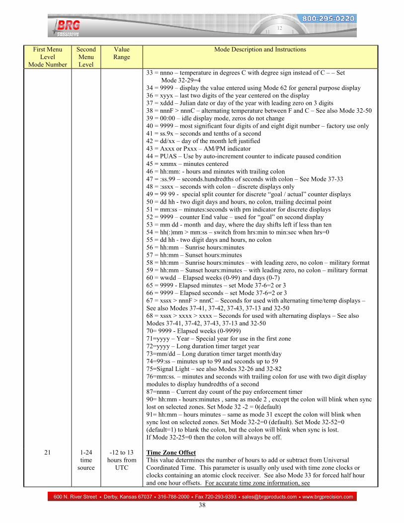
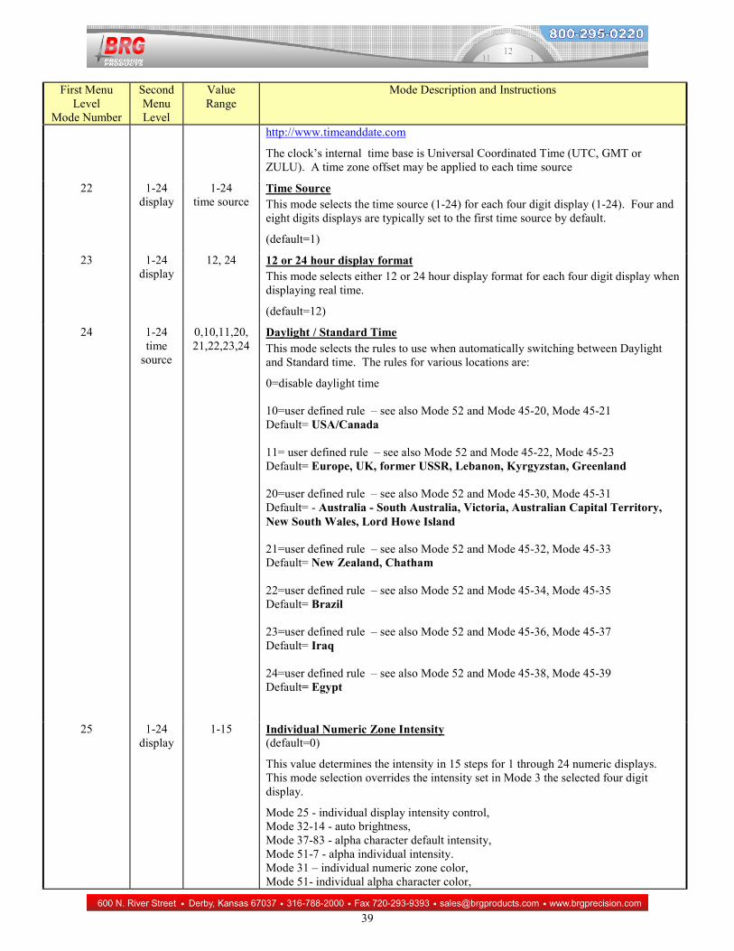
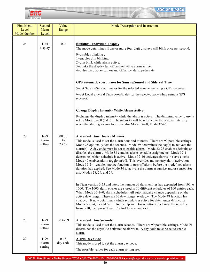
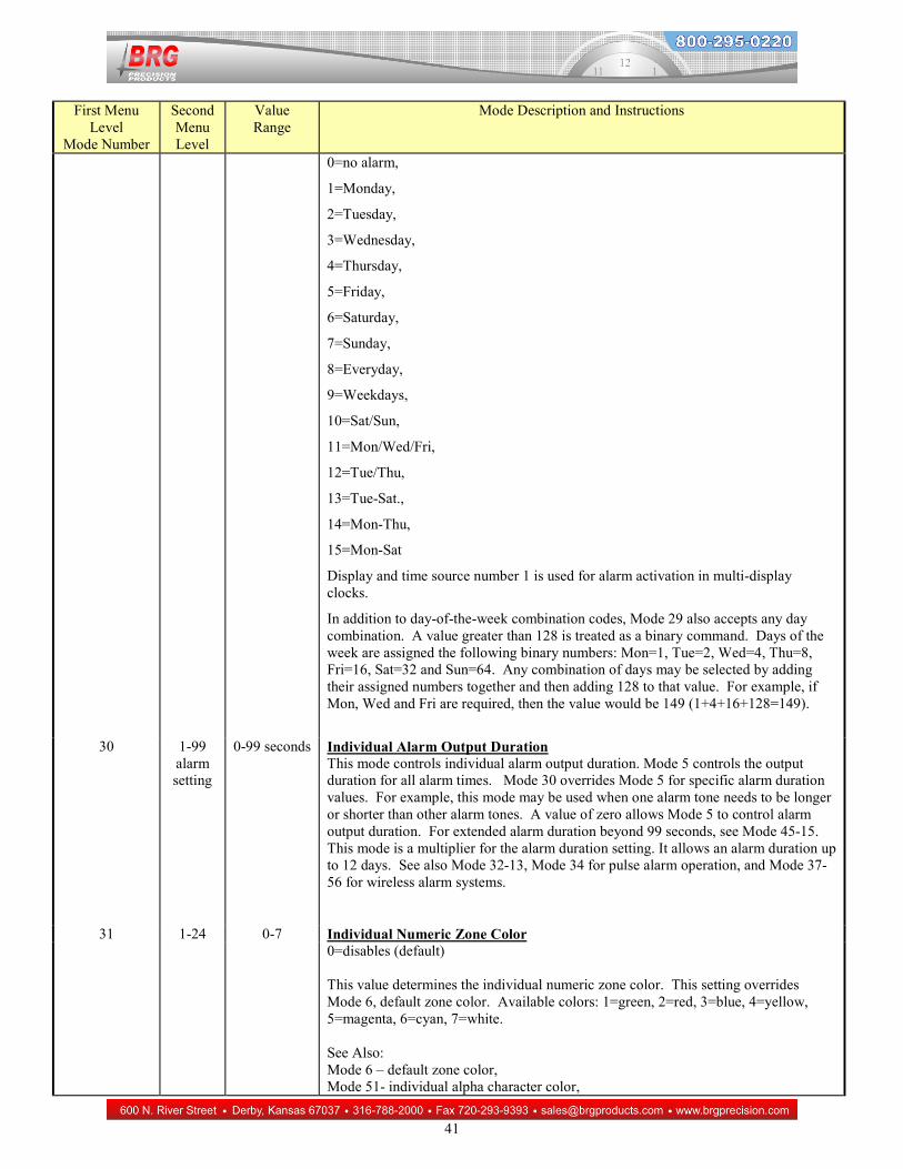
The display format values are: 1 = ss xx – seconds xx, where xx is blank 2 = hh:mm - hours:minutes 3 = hh(:)mm - hours(:)minutes with blinking colon 4 = yyyy - four digit year 5 = mm dd - month and day 6 = ddd – Julian date or day of the year 7 = j j j j – lower four digits of Modified Julian date 8 = x j j j – upper three digits of Modified Julian date 9 = xxxx – blank display 10 = xx ss - xx seconds, where xx is blank 11 = ss.99 – seconds.hundredths of seconds 12 = mm:ss - minutes:seconds 13 = bs sb – seconds centered in a four digit display 14 = dd dy – day of the year, plus last digit of the year 15 = yddd - last digit of the year plus day of the year 16 = hhhh – display hex digits 17 = dd/mm - day/month for international use 18 = hh:mm > month/day – alternating hours:min and month/day 19 = hh:mm > ddd – alternating hours:min and Julian date (day of the year) 20 = hh.mm – hours and decimal minutes separated by a decimal point 21 = dddd – elapsed days for timer operation – See also Mode 35 and Mode 37-48 22 = hhhh – elapsed hours for timer operation – See also Mode 35 and Mode 37-48 23 = hh:mm > mm dd > yyyy – alternating hours;minutes, month-day, and year. 24 = nnnF – Temperature in degrees F – See also Mode 32-50 25 = nnnC – Temperature in degrees C – See also Mode 32-50 26 = hh:mm > nnnF > nnnC – Alternating hours:minutes, temp F and temp C – See also Modes 37-41, 37-42, 37-43, 37-13 and 32-50 27 = hh:mm – hours up to 99 and minutes for timer operation – set mode 32-2=4 and use Mode 35-2 to set the starting value. 28 = ss xx – seconds xx, where xx is blank – no leading zero 29 = yy xx – yy=last two digits of the year, xx=blank 30 = xx dd – xx=blank, dd= day of the month 31 = hh: mm – hours minutes – with leading zero, see mode 32-52 – military format 32 = nnno – temperature in degrees F with degree sign instead of F – Set Mode 32-29=4
38
First Menu Level
Mode Number
Second Menu Level
Value Range
Mode Description and Instructions
33 = nnno – temperature in degrees C with degree sign instead of C – – Set Mode 32-29=4 34 = 9999 – display the value entered using Mode 62 for general purpose display 36 = xyyx – last two digits of the year centered on the display 37 = xddd – Julian date or day of the year with leading zero on 3 digits 38 = nnnF > nnnC – alternating temperature between F and C – See also Mode 32-50 39 = 00:00 – idle display mode, zeros do not change 40 = 9999 – most significant four digits of and eight digit number – factory use only 41 = ss.9x – seconds and tenths of a second 42 = dd/xx – day of the month left justified 43 = Axxx or Pxxx – AM/PM indicator 44 = PUAS – Use by auto-increment counter to indicate paused condition 45 = xmmx – minutes centered 46 = hh:mm: - hours and minutes with trailing colon 47 = :ss.99 – seconds.hundredths of seconds with colon – See Mode 37-33 48 = :ssxx – seconds with colon – discrete displays only 49 = 99 99 - special split counter for discrete “goal / actual” counter displays 50 = dd hh - two digit days and hours, no colon, trailing decimal point 51 = mm:ss – minutes:seconds with pm indicator for discrete displays 52 = 9999 – counter End value – used for “goal” on second display 53 = mm dd - month and day, where the day shifts left if less than ten 54 = hh(:)mm > mm:ss – switch from hrs:min to min:sec when hrs=0 55 = dd hh - two digit days and hours, no colon 56 = hh:mm – Sunrise hours:minutes 57 = hh:mm – Sunset hours:minutes 58 = hh:mm – Sunrise hours:minutes – with leading zero, no colon – military format 59 = hh:mm – Sunset hours:minutes – with leading zero, no colon – military format 60 = wwdd – Elapsed weeks (0-99) and days (0-7) 65 = 9999 - Elapsed minutes – set Mode 37-6=2 or 3 66 = 9999 – Elapsed seconds – set Mode 37-6=2 or 3 67 = xssx > nnnF > nnnC – Seconds for used with alternating time/temp displays – See also Modes 37-41, 37-42, 37-43, 37-13 and 32-50 68 = xssx > xxxx > xxxx – Seconds for used with alternating displays – See also Modes 37-41, 37-42, 37-43, 37-13 and 32-50 70= 9999 - Elapsed weeks (0-9999) 71=yyyy – Year – Special year for use in the first zone 72=yyyy – Long duration timer target year 73=mm/dd – Long duration timer target month/day 74=99:ss – minutes up to 99 and seconds up to 59 75=Signal Light – see also Modes 32-26 and 32-82 76=mm:ss. – minutes and seconds with trailing colon for use with two digit display modules to display hundredths of a second 87=nnnn – Current day count of the pay enforcement timer 90= hh:mm - hours:minutes , same as mode 2 , except the colon will blink when sync lost on selected zones. Set Mode 32 -2 = 0(default) 91= hh:mm – hours minutes – same as mode 31 except the colon will blink when sync lost on selected zones. Set Mode 32-2=0 (default). Set Mode 32-52=0 (default=1) to blank the colon, but the colon will blink when sync is lost. If Mode 32-25=0 then the colon will always be off.
21 1-24 time
source
-12 to 13 hours from
UTC
Time Zone Offset This value determines the number of hours to add or subtract from Universal Coordinated Time. This parameter is usually only used with time zone clocks or clocks containing an atomic clock receiver. See also Mode 33 for forced half hour and one hour offsets. For accurate time zone information, see
39
First Menu Level
Mode Number
Second Menu Level
Value Range
Mode Description and Instructions
http://www.timeanddate.com
The clock’s internal time base is Universal Coordinated Time (UTC, GMT or ZULU). A time zone offset may be applied to each time source
22 1-24 display
1-24 time source
Time Source This mode selects the time source (1-24) for each four digit display (1-24). Four and eight digits displays are typically set to the first time source by default.
(default=1)
23 1-24 display
12, 24 12 or 24 hour display format This mode selects either 12 or 24 hour display format for each four digit display when displaying real time.
(default=12)
24 1-24 time
source
0,10,11,20, 21,22,23,24
Daylight / Standard Time This mode selects the rules to use when automatically switching between Daylight and Standard time. The rules for various locations are:
0=disable daylight time 10=user defined rule – see also Mode 52 and Mode 45-20, Mode 45-21 Default= USA/Canada 11= user defined rule – see also Mode 52 and Mode 45-22, Mode 45-23 Default= Europe, UK, former USSR, Lebanon, Kyrgyzstan, Greenland 20=user defined rule – see also Mode 52 and Mode 45-30, Mode 45-31 Default= - Australia - South Australia, Victoria, Australian Capital Territory, New South Wales, Lord Howe Island 21=user defined rule – see also Mode 52 and Mode 45-32, Mode 45-33 Default= New Zealand, Chatham 22=user defined rule – see also Mode 52 and Mode 45-34, Mode 45-35 Default= Brazil 23=user defined rule – see also Mode 52 and Mode 45-36, Mode 45-37 Default= Iraq 24=user defined rule – see also Mode 52 and Mode 45-38, Mode 45-39 Default= Egypt
25 1-24 display
1-15 Individual Numeric Zone Intensity (default=0)
This value determines the intensity in 15 steps for 1 through 24 numeric displays. This mode selection overrides the intensity set in Mode 3 the selected four digit display.
Mode 25 - individual display intensity control, Mode 32-14 - auto brightness, Mode 37-83 - alpha character default intensity, Mode 51-7 - alpha individual intensity. Mode 31 – individual numeric zone color, Mode 51- individual alpha character color,
40
First Menu Level
Mode Number
Second Menu Level
Value Range
Mode Description and Instructions
26 1-24 display
0-9 Blinking – Individual Display The mode determines if one or more four digit displays will blink once per second.
0=disables blinking , 1=enables dim blinking, 2=dim blink while alarm active, 3=blinks the display full off and on while alarm active, 4=pulse the display full on and off at the alarm pulse rate.
GPS automatic coordinates for Sunrise/Sunset and Sidereal Time
5=Set Sunrise/Set coordinates for the selected zone when using a GPS receiver.
6=Set Local Sidereal Time coordinates for the selected zone when using a GPS receiver.
Change Display Intensity While Alarm Active
9=change the display intensity while the alarm is active. The dimming value to use is set by Mode 37-60 (1-15). The intensity will be returned to the original intensity when the alarm goes inactive. See also Mode 37-60, Mode 37-46.
27 1-99 alarm setting
00:00 to
23:59
Alarm Set Time Hours / Minutes This mode is used to set the alarm hour and minutes. There are 99 possible settings. Mode 28 optionally sets the seconds. Mode 29 determines the day(s) to activate the alarm(s). A day code must be set to enable alarm. Mode 32-23 enables (default) or disables the alarms. Mode 38 contains alarm schedule assignments. Mode 37-1 determines which schedule is active. Mode 32-16 activates alarms in slave clocks. Mode 49 enables alarm toggle on/off. This overrides momentary alarm activation. Mode 37-2=1 enables snooze function to turn off alarm before the predefined alarm duration has expired. See Mode 34 to activate the alarm at sunrise and/or sunset See also Modes 28, 29, and 59.
In Tiger version 3.75 and later, the number of alarm entries has expanded from 100 to 1000. The 1000 alarm entries are stored in 10 different schedules of 100 entries each. When Mode 37-1=0, alarm schedules will automatically change depending on the active date range. There are 20 date ranges available. The Mode 38 function has changed. It now determines which schedule is active for date ranges defined in Modes 53, 54, 55 and 56. Use the Up and Down buttons to change the schedule from 0-10, then press Timer Control to save and exit.
28 1-99 alarm setting
00 to 59 Alarm Set Time Seconds This mode is used to set the alarm seconds. There are 99 possible settings. Mode 29 determines the day(s) to activate the alarm(s). A day code must be set to enable alarm.
29 1-99 alarm setting
0-15 day code
Alarm Day Code This mode is used to set the alarm day code.
The possible values for each alarm setting are:
41
First Menu Level
Mode Number
Second Menu Level
Value Range
Mode Description and Instructions
0=no alarm,
1=Monday,
2=Tuesday,
3=Wednesday,
4=Thursday,
5=Friday,
6=Saturday,
7=Sunday,
8=Everyday,
9=Weekdays,
10=Sat/Sun,
11=Mon/Wed/Fri,
12=Tue/Thu,
13=Tue-Sat.,
14=Mon-Thu,
15=Mon-Sat
Display and time source number 1 is used for alarm activation in multi-display clocks.
In addition to day-of-the-week combination codes, Mode 29 also accepts any day combination. A value greater than 128 is treated as a binary command. Days of the week are assigned the following binary numbers: Mon=1, Tue=2, Wed=4, Thu=8, Fri=16, Sat=32 and Sun=64. Any combination of days may be selected by adding their assigned numbers together and then adding 128 to that value. For example, if Mon, Wed and Fri are required, then the value would be 149 (1+4+16+128=149).
30 1-99 alarm setting
0-99 seconds Individual Alarm Output Duration This mode controls individual alarm output duration. Mode 5 controls the output duration for all alarm times. Mode 30 overrides Mode 5 for specific alarm duration values. For example, this mode may be used when one alarm tone needs to be longer or shorter than other alarm tones. A value of zero allows Mode 5 to control alarm output duration. For extended alarm duration beyond 99 seconds, see Mode 45-15. This mode is a multiplier for the alarm duration setting. It allows an alarm duration up to 12 days. See also Mode 32-13, Mode 34 for pulse alarm operation, and Mode 37-56 for wireless alarm systems.
31 1-24 0-7 Individual Numeric Zone Color 0=disables (default)
This value determines the individual numeric zone color. This setting overrides Mode 6, default zone color. Available colors: 1=green, 2=red, 3=blue, 4=yellow, 5=magenta, 6=cyan, 7=white. See Also: Mode 6 – default zone color, Mode 51- individual alpha character color,
General purpose clock sync indicator using decimal point or blinking colon,
0=disable (default),
1=enable. While enabled, the PM indicator will flicker at the top of the minute if the displayed time is in sync with a radio sync pulse, wired sync data, GPS time receivers.
2= if SR sync signals received, then change the display mode to 3 (blinking colon).
3=if SR sync signal lost then blink the colon.
Set 32-15=7 to activate the sync indicator on the SR port (Ethernet and wire sync)
See also Mode 37-65 to configure the sync status timeout delay and Mode 32-41 to blank the display when sync is lost.
32 2 0-4 Sync Status Special Sync indication using decimal point or blinking colon
0=disabled,
1=turn on decimal when sync received (default), (GPS//IRIG-B)
Mode 32-15 must be greater than 0.
2=turn on decimal when sync is lost, (GPS/IRIG-B)
Mode 32-15 must be greater than 0.
3=blink colon once per second when sync received (must use display mode 2) (GPS/ IRIG-B/Ethernet)
4=blink colon once per second when sync is lost (must use display mode 2) (GPS/ IRIG-B/Ethernet).
5=change numeric display color to the value indicated in Mode 6 when is sync received. When sync is lost change the color to the value in Mode 32-80. See also Mode 32-80
Setting Mode 51-7-n=16 (where n is the alpha character position) will blink one or more alpha characters once per second. Mode 51-7 is used to indicate which character positions are to blink. If no sync source is used, setting Mode 32-2=4 will blink the designated characters continuously. See also Mode 51-7.
See also Mode 37-65 to configure the sync status timeout delay and Mode 32-41 to blank the display when sync is lost.
32 3 1-24 Numeric Display Fields
43
First Menu Level
Mode Number
Second Menu Level
Value Range
Mode Description and Instructions
This value determines the number of zone fields to use for a rotating zone display. (default=1) This mode is usually used in conjunction with digital alpha zone lettering. For example, a display that has four physical zones, but needs to display eight zones total, could alternate the display four zones at a time. For this example, Mode 32-3 would be set to 2. Mode 51-1, Mode 51-2, and Mode 51-4 controls the zone lettering rotation.
If there are two 2 physical numeric zones, set mode 18=2. If the display is to page four times, set Mode 32-3=4. If each of the two zones has 10 physical matrix displays, set Mode 51-2=20. Enter the matrix letter in Mode 51-1, position 1 through 80.
32 4 0-3 Timer Control Action 1=resume real time when End time is reached.,
2=stay in timer mode when End time is reached,
3=enable split time display (default).
4=enable alarm schedule switching (Tiger version 4.00 or later)
Timer operations are maintained during a loss of power. When the power is restored, the correct count will display (version 1.77 and later). If mode 32-4=1, the timer will switch immediately to real time when the End time is reached. If a delay is required before switching back to real time, then set mode 32-4=2 and set mode 32-7 to the minutes of delay before returning to real time. If mode 32-4=2 and mode 32-7=0, then the timer will remain in timer mode when the End is reached. The code blue line overrides the start button. Mode 34-n=99 auto-starts code blue timer from a real time alarm setting. Mode 34-n=99 auto-starts code blue timer from a real time alarm setting. Mode 32-4=3 enables the split time display. The Start and Stop buttons operate the timer. Momentarily pressing the timer control button while the timer is running freezes the display for the number of seconds specified by Mode 32-31. The default is 3 seconds. The timer continues to run while the display is frozen. See also Mode 32-31. See also Mode 32-13 to activate the Timer Control using the real time alarm schedule.
32 5 0,1 Timer control Timer/Counter Direction 0=up (default),
1=down.
32 6 0-3 External Timer Control Line 0=momentary contact closure, (default)
1 or 2=constant contact closure.
3=one time start from real time.
0=A momentary contact closure will switch the display from real time to timer mode, reset the timer, then starts the timer running. Each time the code blue line is pulsed, the timer resets and restarts.
A value of either 1 or 2 will cause the timer to run as long as the contact is closed, and stop the timer when contact opens.
1 = timer will be reset each time the timer is started,
2 = time will accumulate and will not reset when timer started. Mode 32-6 overrides
44
First Menu Level
Mode Number
Second Menu Level
Value Range
Mode Description and Instructions
the start button. The stop/reset button only resets the timer in this mode.
3 = allows the timer to start from real time once only. The code blue line may be momentarily closed or constantly closed to start the timer. Once out of real time and into timer mode, the code blue button has no effect. The start and reset buttons work normally when a value of 3 is used. Mode 34-n=99 auto-starts code blue timer from a real time alarm setting. See also Mode 26-7 and 26-8.
32 7 0-99 Timer to Real Time Switch Delay This parameter determines if or when the timer will resume real time display after the timer is paused. Resetting the timer will cause it to remain in timer mode. For example, pressing Up or Down while the timer is running will pause the timer and it will return to real time after the designated delay period. But, pressing Down again will reset the timer back to the Starting value and the timer will remain in timer mode.
0=disabled,
1-99 = minutes.
If 32-37=1, then pressing the timer control button while the timer is stopped or paused, will return to real time. Set mode 32-4=2 when using this mode.
32 8 0-2 UTC/Local Time Serial Receive
0 = Receive UTC time on RS-422, Sets hours, minutes and seconds (no date) when receiving IRIG-B/SMPTE/ESE time codes.
1 = Receive local time on RS-422. This mode is used when the slaves are to display the same time as the master or computer. (default) Sets minutes and seconds only (no hours or date) when receiving IRIG-B/SMPTE/ESE time codes.
2 = This mode is used to cancel daylight savings time when sending time from a computer to a time zone display. Set Mode 45-5 to the time zone of the time received. For example, if CDMA is used to receive the time, set Mode 45-5 to the local offset from UTC. Also, set Mode 32-65 to the local daylight saving rule in version 4.28 and later. The default is U.S. daylight saving time.
3 = Receive UTC time from BRG IRIG-B on the GPS port, Sets hours, minutes and seconds (no date) when receiving IRIG-B time codes. Set Mode 32-15=7.
4 = Receive local time from BRG IRIG-B on the GPS port. This mode is used when the slaves are to display the same time as the master or computer. Sets minutes and seconds only (no hours or date) when receiving IRIG-B time codes. Set Mode 32-15=7.
See also Mode 45-5 to set the incoming time zone offset.
32 9 0,1 UTC/Local Time Serial Transmit 0 = transmits UTC time on RS-422,
32 11 0,1,2 Mode and Display Format Switching Over Serial Sync Line
0 = disable auto mode and format switching from serial data received (default)
1 = enable operating mode and display format switching
45
First Menu Level
Mode Number
Second Menu Level
Value Range
Mode Description and Instructions
2 = enable operating mode switching only
5 = Low speed IR remote control test. Use the control buttons to set this Mode 32-11=5, not the remote.
A value of 1 allows time packets received to change the operating mode (Mode 14) and the display formats for zones 1 and 2 (Modes 20-1 and 20-2). A value of 2 changes the operating mode, but does not change the display format. This setting is recommended when using the clock with a Time Commander timer. This allows the Time Commander to drive displays with a variety of display configurations.
32 12 0-3 Serial Sync Transmission 0 = disable serial sync output (default),
1 = enable serial sync output with variable delay in real time only.
2= enable serial sync output with variable delay.
3=enable serial sync output with variable delay in real time.
4=transmit time sync out SR/ST port only to control radio paging transmitter If Mode 37-59=0 then 35 byte data will also be sent out the GPS port once per minute. In this case, also set Mode 32-15=7.
5= transmit time sync out GPS port only to control radio paging transmitter If Mode 37-59=1 then 35 byte data will also be sent out the SR/ST port once per minute. In this case, also set Mode 32-15=7.
Enable this function if the clock is to be a master clock not connected to other time sources. Disable sync output if clock is a slave, or it is receiving time from a PC. Enable if clock is to server as a master clock sending time to other clocks or a PC.
Wireless Master Clock Configuration Examples 1. Receive Ethernet on SR/ST, transmit time on GPS port. 32-12=5, 32-15=7 – also 21-1=n, 24-1=n, 32-8=0 2. Receive Motorola GPS on GPS port, transmit time on SR/ST port 32-12=4, 32-15=2 – also 21-1=n, 24-1=n, 32-8=0 3. Receive NMEA083 GPS on GPS port, transmit time on SR/ST port 32-12=4, 32-15=11 – also 21-1=n, 24-1=n, 32-8=0 4. Receive CDMA GPS on GPS port, transmit time on SR/ST port 32-12=4, 32-15=10 5. Receive IRIG-B on GPS port, transmit time on SR/ST port 32-12=4, 32-15=4 – also 21-1=n, 24-1=n, 32-8=0
See also Mode 45-9 to alter the sync transmission rate.
32 13 0-94 Alarm Pulsing 0 = disable alarm output pulsing for all alarm settings (default).
1-94 = alarm pulses per second for all alarm settings.
If this setting is 0, when the alarm sounds, it will remain on for the entire selected alarm duration period. A value of 1 – 94 determines the number of times the alarm is pulsed per second. For example, if the alarm duration is set for three seconds and
46
First Menu Level
Mode Number
Second Menu Level
Value Range
Mode Description and Instructions
Mode 32-13 is set for 2 pulses per second, the alarm will turn on and off six times throughout the three second alarm duration period. See also Mode 34 for individual alarm pulsing override and mode 26.
32 14 0-15 Auto Brightness Option (factory installed light sensor option required) 0 = disable optional auto brightness control,
1-15 optional auto brightness offset to all display intensity. This option is typically used in areas where lighting conditions change such as video conferencing rooms and communications centers.
32 15 0-10 Special Controls and Devices 0=no special devices present (default), (GPS=9600, SRST=9600/600),
2=GPS receiver, (GPS=9600, SRST=9600/600) . In addition to setting the time and date, coordinate data may be set to calculate Sunrise/Sunset and Sidereal time. See also Mode 26 and Mode 45-14 (ver.3.26) ,
4=SMPTE/IRIG-B/ESE receiver, (GPS=2400, SRST=9600/600), (see also 32-15=13)
For BRG IRIG-B, set Mode 32-15=7 and Mode 32-8=3. (Ver 3..44 or later) BRG IRIG-B does not support SMPTE or ESE.
7=Use the GPS port for 9600 baud serial sync and the SR/ST port 9600 baud serial sync , (GPS=9600, SRST=9600), This is the same setup as 0 except serial sync transmits on the GPS port and the sync light will activate when sync data is received.
8=9600 baud SR/ST port and 9600 or 600 baud GPS port (GPS=9600/600, SRST=9600)
9=Enable Mode 32-56 and Mode 32-57 – selectable serial port baud rate
11=NMEA-0183 National Marine Electronics Association (NMEA) standard for communicating GPS data. For BRG GPS, set Mode 32-15=7. Only the $GPRMC sentence is used. Data must be valid before the time will be used. The time will update once per hour. The sync indicator will disable after 90 minutes of no GPS data received. Display mode 16 will display 1 1 when the time is received. It does not display the number of satellites. In addition to setting the time and date, coordinate data may be obtained to calculate Sunrise/Sunset and Sidereal time. See also Mode 26, Mode 45-18, 32-64 and Mode 32-69.
13=Second generation IRIG-B receiver - (GPS=9600, SRST=9600/9600) – IRIG-B does not provide date information, only time. For BRG IRIG-B, set Mode 32-15=7 and Mode 32-8=3. (Ver 3..44 or later) BRG IRIG-B does not support SMPTE or ESE.
Examples:
0=Serial sync transmits or receives on SRST port.
0=Serial sync receives on GPS port, Ethernet sync transmits on SRST port.
2=GPS receives on GPS port and serial sync transmits/receives on SRST port.
47
First Menu Level
Mode Number
Second Menu Level
Value Range
Mode Description and Instructions
7=Serial sync transmits on GPS port, Ethernet sync receives on SRST port.
use the clock’s control buttons. Once set, the date will increment normally.
32 16 0-2 Alarm master/slave control 0=disable (default),
1=enable separate start/stop and warning alarms
2= combine start/stop and warning alarms into the main relay output
When using wired sync, slave clocks may follow the alarm sounding of a master clock. This allows one clock to control the alarm sounding of several alert horns. For example, one master clock could contain the alert horn schedule for the entire plant. Several slave clocks with the AL or AH alert horn options could be controlled by the alarm schedule of the master clock. Both Master and Slave clock must have Mode 32-16 enabled for this method to operate. Set to a value of 2 to activate the slave relay when either start/stop or warning alarms are activated.
32 17 0,1 Timer Direction Auto-reverse
For short duration timers only
Direction reverse duration timers requires setting Mode 32-26=2
0 = do not reverse timer direction when the end time is reached, (default)
1 = When the end time is reached., reverse timer direction from down to up and continue with elapsed time This only applies to a down timer.
Mode 13 is ignored.
Direction reverse for medium duration timers requires version 4.50 or later.
32 18 0,1 Long Duration Elapsed Time 0 = Starting time and day is not set on power-up, (default)
1 = set the Starting time and day from target time and date on power-up or when exiting the menu.
This mode is typically used with long term elapsed timers so that if power is lost, the timer will resume correct operation when the power is restored. While in long duration timer mode, pressing the timer control button will temporarily switch to real time operation. At this point, you can change the time, and by pressing the mode button, you enter the menu system to change the real time month, day and year. Pressing the timer control button again will return to long duration timer mode.
Modes 37-34, 37-35 and 37-36 determines the display format used for long duration timer operation. See also Modes 32-17, 32-21, 37-40.
Mode 44-1- starting month and day Mode 44-2 - starting year Mode 9 – starting hour and minutes
48
First Menu Level
Mode Number
Second Menu Level
Value Range
Mode Description and Instructions
When counting down to a future time and date, the timer will stop at the target time and date is reached. If you want to pass through the target time and begin displaying the elapsed time from the target time, then set Mode 32-17=1. This will enable the auto-reverse feature. Mode 13 is ignored when Mode 32-17=1. Mode 32-21 allows time updates from an external source to maintain the accuracy of a long duration timer.
See also Mode 37-49 for displaying days and hours on an alpha display.
32 19 1-24 Timer Time Zone Applies only when Mode 32-18=1. This value must point to the appropriate time zone if a time zone offset value is used. For example, if a GPS receiver is connected to a single display and a time zone offset from UTC is used, then the mode 32-19 value must equal 1. (default=1)
32 20 0-3 RS422 Configuration
0=both RS422 ports disabled, 1=SRST RS422 port enabled, GPS RS422 port disabled, 2=(default) SRST RS422 port disabled, GPS RS422 port enabled, 3=SRST RS422 port enabled, GPS RS422 port enabled. RS422 should be disabled if the port is used for any other serial communications. Enabling RS422 on the SRST port may interfere with high speed IR communications. The GPS RS422 is enabled by default to allow programming. If GPS will be used, disable the GPS RS422 port after programming.
1= Allow time from RS422 sync wire or GPS or CDMA to update real time clock while in timer or counter mode. Only the seconds are updated in counter mode. This increases the accuracy of the elapsed timer. This feature is intended to prevent the timer from running at a different rate than the real time clock. When this mode is active, the timer will not increment unless sync data is received once per second. When sync data is receive, the timer seconds are set to the sync seconds received. A down timer will use the difference between sync seconds received and 59 to produce the correct value. 2=Updates the time and date while in timer or counter mode. A setting of 1 only updates seconds while in counter mode.
32 22 0,1 Timer - Simple Button Control Operation 0=disable (default) 1=enable This mode activates the timer simple button control operation. When enabled, pressing the TC button will cycle through the display zones. Press the TC button once to select the first zone, causing the zone to blink. Once a zone is blinking, the Up and Down buttons may be used to change the value of that zone. Pressing and holding the Up or Down buttons will cause the value to change faster after several seconds. Press the TC button again to move to the next zone. After the last zone is selected, the display will return to normal operation. The TC button may also be used to toggle between Up and Down timer operation. During normal display operation, press and hold the TC button for about 4 seconds. Once zone 1 display blinks, release the TC button to toggle the timer operation. To determine the timer direction, press the Up button to determine if the timer is in the Up or Down direction. The simple
Setting Mode 13=1 will stop a countdown timer when 0 is reached. Setting Mode 32-17=1 will cause a down timer to reverse direction at 0.
32 23 0,1 Scheduled Alarm Time Activation 0=deactivate scheduled alarms,
1=activate scheduled alarms (default).
32 24 0,1 Close Alarm Relay When Timer Started and/or Stopped 0=deactivate (default),
1=activate alarm when timer started,
2=activate alarm when timer stopped,
3=activate alarm when timer started and stopped
4=activate the alarm while the timer is running. Also, set Mode 32-10=0 (default)
This selection will cause the alarm relay to activate when the timer is started and/or stopped The alarm will activate for a period determined by the alarm duration value ( Mode 5). See also Mode 37-9.
32 25 0,1 Colon Status for Display Modes 91
0 = Disable Colon
1 = Enable Colon (default)
32 26 0-2 Dual Relay Output Use Display Mode 75 for addressable LED signal lights. Set Mode 32-26=2 to enable color change.
0=disabled (default)
1=enabled - Red/Yellow/Green light mode using two relays – also set Mode 43-1=2,
2=enable addressable LED signal light control. Also, used to enable using internal transistor array. This value also enables four channel relay output. If the four channel relay option is installed, then the clock expects at least one alarm setting for relays 2,3 or 4. If relays 2,3 or 4 are not included in any alarm scheduled at this time, then set Mode 59-99=16. This will cause the relays to correctly initialize at power up. When Mode 32-26=1, then set Mode 37-12=0.
See also:
Display mode 75 – signal light display installed
Mode 32-82 – configure display color change when signal light is unavailable
Mode 43-1 through 43-5 to configure warning alarms
Mode 32-17 – Reverse direction at the end time
32 27 0,1 Automatic Color Dependent Display Intensity 0=Disabled, maximum intensity allowed for all display colors 1=(default) Limited display intensity depending on color selected.
50
First Menu Level
Mode Number
Second Menu Level
Value Range
Mode Description and Instructions
This feature prevents a possible loss of control and/or display damage when using high intensity with certain colors. White is limited to an intensity of 6, yellow, magenta and cyan are limited to an intensity of 8, and red, blue and green are not limited. After exiting the clock menu, the color and intensity are examined and the intensity modes 3, 25 and 51-7 are adjusted as necessary to eliminate overheating. Mode 32-27 may be disabled for outdoor clocks that need a brighter display for the colors yellow, cyan, magenta or white. Colors red, blue and green already allow maximum intensity. The display intensity is also limited for moving message displays and cannot be disabled.
32 28 0,1 Leading Zero Blanking on Selected Display Modes
0=disabled,
1=enabled (default)
The effected display modes include 4,5,6,7,17,19,21,22,23,30,37,52,55 and some menu functions. This mode also controls the leading zero blanking for the special characters of digital alpha lettering. See also mode 20-31.
32 29 0-7 Reset and Initialize Display Drivers This mode periodically resets and initializes numeric display drivers (including alpha digits on the numeric buss). The alpha drivers are not affected.
0=disabled,
1=fast, but only if 4 physical zones or more,
2=fast display reset, reboot daily,
3=reset displays once per min, reboot daily,
4=(default) reset displays once per hour,
5=reset displays once per day,
6=reboot once per day
7=reboot once per hour if sync not received in last hour (do NOT use for wireless transmitters)
Alpha digits on the numeric data buss will flicker if refresh rate is too fast.
32 30 0,1 Special Serial Sync Control Codes 0=disable, receipt of special control codes over the sync wire, (default)
1=enable receipt of special codes.
This mode allows other clocks on the same sync circuit to ignore these control codes.
1-enabled - use alarm relay for midnight sync output.
Example: Send a 100 ms pulse at 3:00 am over radio sync using the alarm relay. Mode 6=1 Mode 16= 3:00 Mode 17= 00 Mode 32-33=1 Mode 37-3=1 Mode 45=8=100
1= seven segment digits - use display intensity to daytime/nighttime
2= seven segment digits - use decimal point to indicate daytime/nighttime
3= seven segment digits - use display color to indicate daytime/nighttime. Mode 32-36 indicates nighttime color. The default zone color will be used to indicate daytime.
4= all matrix display - use display intensity to indicate daytime/nighttime. Mode 3 determines the daytime intensity. Mode 32-36 determines the nighttime intensity. Only zone 1 SRSS time is used to determine when to change.
5= Use display color to indicate daytime/nighttime. Mode 32-79 determines the default daytime color. Mode 32-36 determines the default nighttime color. Only zone 1 SRSS time is used to determine when to change color.
See also, Modes 32-36, Mode 32-79, Modes 61, 62, 63, 64 and Display Modes 56, 57, 58 and 59.
32 36 1-15 Display Intensity or Zone Color to Indicate Nighttime for each respective time zone Default = 7. For intensity, the range is 1-15 For color, the range is: 1=green 2=red 3=blue 4=yellow 5=magenta 6=cyan 7=white See also, Modes 32-35, Modes 61, 62, 63, 64 and Display Modes 56, 57, 58 and 59.
32 37 0,1 Return to Real Time from Timer Mode 0=disabled (default),
1=Pressing the timer control while the timer is stopped or paused will return the display to real time. See also Mode 32-45.
32 38 0-3 Send Time to Message Boards This function is normally removed from the code set. 0=disabled 1=send intensity every 10 seconds 2=(default) send intensity every 10 minutes 3=send intensity hourly If the mode is greater than 0, then time updates are sent to the message board bourly.
32 39 0,1 Display Absolute Value 0-disabled (default),
1=enabled – Display the absolute value of various four digit counter and timer display modes. This effectively removes the negative sign when the value is less than zero.
52
First Menu Level
Mode Number
Second Menu Level
Value Range
Mode Description and Instructions
32 40 0-9 Ethernet Interface NTP Time Correction
0=disabled (default),
1-9=number of seconds to add to the time received
This delay is used in conjunction with Mode 45-17. The value in Mode 32-40 is the number of seconds to add to the time received over serial sync communications. A delay is then applied to add fractional seconds to the time received. This will effectively cancel the delay caused by the time required to send the time over a serial communications line. This mode will not work with once per second sync. Once per minute sync or greater is recommended. See also Mode 32-40, 32-64, 45-17, 70, and 71.
32 41 0,1,7 Refresh Display prior to Serial Data Transmission and Blank Display When Sync is Lost 0=enabled (default),
1=disabled. When enabled, the displays will be refreshed just prior to sending serial sync data.
7= Display zone 1, Display Modes 2 and 10 will blank when sync is lost. The decimal point will display while the display is blanked.
32 42 0-99 Clock Address for PC Control, Moving Message Marquee and Remote Control (default=0) When sending control data to clocks, individual clocks or moving message displays may be addressed by including the clock’s address. If the address value sent equals the value specified in this mode, then the clock will accept the data packet. For PC control, all clocks may be addressed by sending address 0. For addressable remote control operation, hold down the Mode button. The display will flicker. Continue holding down the Mode button until the clock’s address appears then release the mode button to access that clock’s menu system. See also Mode 37-29, 32-49, 32-55 and 32-59.
1=The moving message data, without header, address and footer, is sent out the GPS port. Data received on the SR/ST port will only be sent out the GPS port if the address received equals zero or the address received equals the address set in mode 32-42. , (default) Tiger version 4.06 or later. Increase the inter-packet delay in the Windows control program when sending to a wireless master clock.
2=The complete 35 byte moving message string received on the SR/ST port is repeated out the GPS port.
3= The moving message data received on the SR/ST port is sent out the SR/ST port. The data will only be sent out the SR/ST port if the address received equals zero or the address received equals the address set in mode 32-42. ,
4=The complete 35 byte moving message string received on the SR/ST port is repeated out the SR/ST port.
5= The moving message data, without header, address and footer, is sent out the SR/ST port. Data received on the SR/ST port will only be sent out the SR/ST port if the address received equals zero or the address received equals the address set in mode 32-42. , (default) Tiger version 4.06 or later. Increase the inter-packet delay in
53
First Menu Level
Mode Number
Second Menu Level
Value Range
Mode Description and Instructions
the Windows control program when sending to a wireless master clock.
6= The moving message data, without header, address and footer, is sent out the SPI port. Data received on the SR/ST port will only be sent out the SPI port if the address received equals zero or the address received equals the address set in mode 32-42.
To send decoded data out the GPS port and raw data out the SR/ST port, set 32-44=1, remove pin 2 from the RS422 chip on the SR/ST port and jumper SR/ST.
32 45 Display format number
Switch to Real Time Display Format
This mode is for use with timer versions prior to version 1.77. Versions 1.77 and later restore the display format when returning to real time from timer mode. This mode is still available for special applications.
This mode determines which display format to use when switching from timer to real time display. Available in version 3.59 or later. If 0, the all displays modes will be restored. If greater than 0, then the value supplied will be used in zone one and zones 2 and 3 will be blank.
32 46 0,1 Ethernet Interface Hardware Reset
To restore the Ethernet interface back to factory defaults, press and hold the yellow mode button. The display will slowly begin counting up. When the count reaches 8, release the mode button and momentarily press the blue TC button. 0 = disabled, 1 = reset c.5 daily, 2 = reset c.5 daily, 3 = reset c.5 hourly, 4=reset c.5 hourly, 5 = reset c.5 and a.4 if no time update is received for one hour (default), 6 = reset c.5 if no time update is received for one hour.
32 47 0-3 Repeat Clock Control Commands Control commands coming in the SR/ST port are repeated out the ST port, GPS port, or both.
0=disabled (default),
1=SR/ST port ,
2=GPS port,
3=both.
32 48 0,1 Ethernet Control Port 0=SR/ST port (default),
1=GPS port.
For example, if an Ethernet interface is connected to the SR/ST port and the GPS port is used to send serial sync data, set Mode 32-15=7 to set both ports to 9600 baud, and Mode 32-48=0.
32 49 0-99 Menu Lockout Timer – (1=default) This mode determines the number of minutes from the last menu access before the buttons are locked out again. This mode can be
54
First Menu Level
Mode Number
Second Menu Level
Value Range
Mode Description and Instructions
used in conjunction with the remote control address Mode 37-29. See also Mode 32-42 and 32-55.
32 50 0,3 Temperature Sensor - 0=disabled, 1=(default) enable temperature sensor. 2=enable temperature sensor and send temp data over serial sync port. 3=receive temperature data from serial sync port. Available in real time only and with serial wire sync and Ethernet UDP. See also Modes 32-75, 45-16, and 46-1 See also display modes 24, 25, 26, 32, 33 and 38.
32 51 0,1,2 Timer Transmit Control – 0=disabled (default), 1=enable using the SR/ST port, 2=enable using the GPS port. This mode allows timer control commands to be sent out the serial sync ports to control other timers. The timers will not be synchronized again once they are started. For timers that require synchronization to the second over long periods, the ultra-high precision oscillator option is recommended. When the Reset button is pressed, the Start, End and warning times will be sent along with a command to reset the timer. Mode 32-12, serial sync transmit, should be disabled, otherwise it may interfere with the commands. When Mode 32-51 is enabled, pressing the Up button on the master clock will send a timer Start command to the slave clock(s). Pressing the Down button will send a timer Reset command. If Mode 37-10=1, then the master clock will reset when the Down button is pressed just like the slave clock. Pressing the Timer Control button will simulate pressing the Timer Control button on the slave clock(s). The slave clocks must be configured as timers and are typically configured identically as the master, except for Mode 32-51. See Mode 37-38 to increase timer accuracy.
32 52 0,1,2 Display Colon -
0=disabled, 1=(default) enable colon in display mode 31, 58 and 59. 2= enable the colon and decimal point in display mode 12.
32 53 0,1 Counter Actual/Goal Difference – 0=place counter actual minus goal in display position 3 (default), 1=place goal minus actual in display position 3.
32 54 0-12 DuraTime Wireless MP3 Alarm Zone Number 0 = disabled 1-12 (1=default) – Alarm zone number This mode allows an RC100 to activate the MP3 player in digital slave clocks. Each alarm setting can use a unique MP3 audio file and zone number. When multiple zones are selected, all clocks matching the selected zones will all play the same audio file.
32 55 0,1 Infrared Remote Control When Using Multiple Clock/Processors
0=disabled (default),
55
First Menu Level
Mode Number
Second Menu Level
Value Range
Mode Description and Instructions
1=enabled A display with multiple processors or multiple stand-alone displays may be configured such that when the mode is pressed, the right-hand decimal point will illuminate on the active display. When the light is on, all buttons function normally on that display. The buttons are disabled on all other displays. To access another display, press the mode button multiple times until the desired display’s decimal point illuminates. When the display is powered on, the display with clock address 1 (Mode 32-42) will be the active display. If it is desired to not have any display active when first powered on, don’t use clock address 1. To configure multiple processors to use a single infrared remote control, set: Mode 32-42 = n (enter an address from 1-99 for each respective processor) Mode 32-49 = 0 – No menu lockout timer is required Mode 32-55 = 1 – Enable multiple processor quick access Mode 37-29 = 1 – Control button lockout must be set to 1, 4, 5 or 6 The Mode button should be pressed at a rate of approximately 2 times per second when moving from display to display. To disable the control buttons on all displays, press the mode button until no decimal indicators are illuminated.
32 58 0,1 Alpha Digital Lettering Menu System - 0=disabled (default), 1=enabled This mode displays the menu system on the digital alpha-numeric lettering in addition to the normal numeric digits. This allows the alpha digits to be used without numeric time digits. See Mode 32-54 to configure the type of digital lettering used. If a clock has only digital lettering and the clock is restored back to factory defaults, control of the clock will be lost. To regain control of a clock using 16 segment lettering, hold down the Up button while power is applied. To regain control of a clocks using 5x7 lettering hold down the Timer Control button while applying power. This will provide enough control to restore customer defaults.
32 59 0,1 Accept or Ignore Global PC Commands – 1=accept (default) 0=reject global address PC commands PC commands received with an address of 0 will be ignored if Mode 32-59=0. This mode also affects global moving message commands received. See also Mode 32-42.
32 60 0-3 SR/ST Port Operation and Ethernet Hardware Reset 0=Ethernet hardware reset (default), 1=ST - receive and local processor transmit 2=SR/ST - hardware repeat, no local processor transmit 3=SR/ST - hardware repeat, with local processor time transmission on ST port (v4.48) For Tiger PC board version 4.5 or older, always set Mode 32-60=0. For Tiger PC board version 4.6 or later, setting Mode 32-60=2 will immediately repeat all serial data received on the SR port out the ST port. The local processor cannot transmit on this port in this mode. The local Tiger processor receives the data, but will not be able to transmit. Setting Mode 32-60=1 allows the local processor to receive and transmit data. The data will not be repeated out the ST port unless the processor is configured to do so. If the data is repeated, a small delay will be introduced due to the time required to process the data. When Mode 60=3, all serial data received on the SR port will be hardware repeated out the ST port, and local time transmissions will also be sent out the ST port. For example, a large time zone display with digital lettering and IRIG-B on the GPS port can repeat all commands received on the SR port out the ST port to other clocks, and also send time out the ST port. For a clock system, it is recommended to set Mode 32-60 to 2 to immediately repeat the data. Each clock will regenerate the data stream and no delays will be introduced. For configurations where the local clock must transmit, as in the case of a master clock, then set Mode 32-60=1 to allow the clock to transmit. See also Mode 32-46 (3.11 5/10/040)
32 61 0,1 Counter/Timer Control Using Real Time Alarms – 0=Disabled (default) 1=Enabled – The real time alarm schedule entered using Modes 27, 28 and 29 will be used to activate timer functions. Mode 49 is used to specify the timer functions required. Auto-incrementing counters are also supported. Alarm groups are not supported.
57
First Menu Level
Mode Number
Second Menu Level
Value Range
Mode Description and Instructions
Mode 49-n=3 – Counter/Timer Reset Mode 49-n=4 – Counter/Timer Pause / Resume (same as Up button) Mode 49-n=5 – Timer Reset and Start (same as Timer Control button) For example, to automatically start the timer at 8:00 am, pause for lunch between 12:00 noon and 1:00pm, and stop the timer at 5:00pm, set Mode 27-1=8:00, Mode 27-2=12:00, Mode 27-3=13:00 and Mode 27-4=17:00. Set Mode 29-1 through Mode 29-4 to the desired day of the week codes. Set Mode 32-61=1 to enable the automatic timer control feature. Set Mode 49-1=5 to start the timer at 8:00. Set Mode 49-2=4 to pause the timer at 12:00 and Mode 49-3=4 to resume the timer at 13:00. Set Mode 49-4=4 to stop the timer at 17:00. Alarm schedule switching (manual or by date range) is also supported. See also Mode 37-1.
32 62 1-24 Serial Transmit Zone –
1 (default) – 24 – Zone to use for serial transmit time data. This applies to serial two wire Ethernet, and power line sync.
32 63 0,1 Display Load Line Level 0=high (default) 1=low – must be used when 16 segment displays are used on the numeric data port. A value of 0 is used when large amounts of digital lettering are used and/or a large number of display zones. This will help reduce display flickering due to interference on long data cables. A value of 1 is required when use 16 segment digital lettering on the numeric data port.
32 64 0,1 Serial Polling Rate 0= (default) 1=Increase the polling rate for serial data received on the SR/ST port. This will increase the reliability of serial data received on slow displays. See also Modes 32-40 and 45-17.
32 66 0-9 Daylight Saving Time End Hour Offset Default=2 (default=2 for 02:00) This mode determines the hour to switch between standard and DST for custom DST rules, both North and South of the Equator, including leap years.
32 67 0-9 Daylight Saving Time Begin Hour Offset Default=2 (default=2 for 02:00) This mode determines the hour to switch between standard and DST for custom DST rules, both North and South of the Equator, including leap years.
32 68 0-5 Time Reception Port Control 0= (default) receive time on both ports if configured otherwise, does not receive remote GPS time packet either over the air or from Ethernet. 1= receive time on SR/ST port only, does not receive remote GPS time packet either over the air or from Ethernet.
58
First Menu Level
Mode Number
Second Menu Level
Value Range
Mode Description and Instructions
2= receive time on GPS port only, does not receive remote GPS time packet either over the air or from Ethernet. 3= do not receive time on any port, does not receive remote GPS time packet either over the air or from Ethernet. 4= receive time on GPS port from a remote GPS receiver over the air. 5= receive time on SRST port from a remote GPS receiver using the Ethernet cable (SRST port). NTP time and other standard time packets will be ignored. 6=receive standard time packets (NTP) over the Ethernet port and time packets over the air from a remote GPS receiver. The configuration provides a redundant time source. If one of the time sources provides incorrect time, the master and slave clocks may jump periodically between the two times. This configuration does not affect the reception of commands, only the reception of time broadcasts.
32 69 0,1 NMEA GPS Operation 0 = Configure GPS receiver to send NMEA GPS data continuously 1 = (default) Configure GPS receiver to send NMEA GPS data once every five seconds at the top of the hour for one minute or until a valid time update is received. Once the GPS receiver is connected to a clock with Mode 32-69 set to 1, the GPS receiver will be disabled until the top of the hour. The GPS receiver will no longer work with older clocks that expect a continuous data stream. To reconfigure a GPS receiver to work with older clocks, set Mode 32-69 to 0, connect the GPS receiver, then cycle power. This will configure the GPS receiver to transmit GPS data continuously.
32 70 0,1,2,3 Enable Serial Port Time Sync Transmissions 0=disable both serial ports 1=enable SR/ST port (default) 2=enable GPS port 3=enable both serial ports This mode is useful to limit time sync transmissions from going out the ports that could interfere with other devices attached to the port. For example, a clock configured with Ethernet on the SR/St port and 900 MHz transmitter on the GPS port should only send time sync out the GPS port, not the SR/ST port. Therefore, Mode 32-70 should be set to 2.
32 75 0-24 Numeric Zone Color Change Based on Temperature 0=disabled (default) 1-24=numeric zone to change color based on the temperature If More 32-75>0 then enable temperature color change. Mode 32-76=65 (default) is the low range in temp F, Mode 32-77=75 (default) is the medium range in temp F, Mode 32-78=80 (default) is the high range in temp F. If the temperature F is less than 65 the display is blue, if between 65 and 75 then green, if between 75 and 80
59
First Menu Level
Mode Number
Second Menu Level
Value Range
Mode Description and Instructions
then yellow, over 80 then red. See also modes 32-50, 32-76, 32-77 and 32-78
32 76 0-150 Zone Color Change Based on Temperature – Low Range 65= Low range Temp F (default) Only positive values may be used If More 32-75>0 then enable temperature color change. Mode 32-76=65 (default) is the low range in temp F, Mode 32-77=75 (default) is the medium range in temp F, Mode 32-78=80 (default) is the high range in temp F. If the temperature F is less than 65 the display is blue, if between 65 and 75 then green, if between 75 and 80 then yellow, over 80 then red.
32 77 0-150 Zone Color Change Based on Temperature – Medium Range 75= Medium range Temp F (default) Only positive values may be used If More 32-75>0 then enable temperature color change. Mode 32-76=65 (default) is the low range in temp F, Mode 32-77=75 (default) is the medium range in temp F, Mode 32-78=80 (default) is the high range in temp F. If the temperature F is less than 65 the display is blue, if between 65 and 75 then green, if between 75 and 80 then yellow, over 80 then red.
32 78 0-150 Zone Color Change Based on Temperature – High Range 80=High range Temp F (default) Only positive values may be used If More 32-75>0 then enable temperature color change. Mode 32-76=65 (default) is the low range in temp F, Mode 32-77=75 (default) is the medium range in temp F, Mode 32-78=80 (default) is the high range in temp F. If the temperature F is less than 65 the display is blue, if between 65 and 75 then green, if between 75 and 80 then yellow, over 80 then red.
32 79 1-7 Sunrise/Sunset Color Change Daytime Color 1-7 2=default (red) This mode determines the daytime default display color. See also Mode 32-25.
32 80 0-7 Change the Numeric Display Color when Sync Received/Lost
7=white This mode is used when Mode 32-2=5. The default numeric display color is changed depending on sync status.
32 81 0-3 Ultra-High Precision Oscillator Support 10 MHz oven or Rubidium oscillator Oven Controlled (OCXO) and Rubidium (RbO) Oscillator Configuration 0=disable ultra-precision support, 1=(default) calibrate the TCXO using the OCXO or RbO once per minute, 2=calibrate the TCXO using the OCXO or RbO once per hour, 3=calibrate the TCXO using the OCXO or RbO once per day 11 MHz Ovenized TCXO oscillator 1=(default) maintain the TCXO at a temperature determined by Mode 6. (default=35C)
32 82 0-3 Display Color Control by Alarm Settings 0=disabled (default) 1=numeric zone follows the signal light color 2=alpha display default follows signal light color 3= numeric and alpha displays follow signal light color This mode is used to change the display color for timer operation when a signal light is not installed. If enabled, all Numeric Zones Will Change Color With The Signal Light Commands. Use Display Mode 75 to control addressable LED signal lights. Example: Class pass countdown timer that changes color using a 4 digit numeric display:
Mode 7=5:00 – starting time Mode 13=1 – stop at end time (0:00) Mode 32-4=1 – Timer Control action Mode 32-5=1 - timer direction Mode 32-8=1 – Receive local time Mode 32-26=2 – Relay action Mode 32-82=1 – Color change by alarm status Mode 32-86=1 – DuraTime 2.4 GHz alarm activation Mode 36-1=12 – Display timer format Mode 37-38 = 1 – Improves timer start accuracy Mode 43-1=4 – enable warning alarm Mode 43-2=1:00 – warning alarm time See also:
Mode 43-1 through 43-5 to configure warning alarms
Mode 32-17=1 – Reverse direction at the end time
32 84 0-99 Automatic Leap Second Adjustment Two Digit Year 0=disabled (default) This mode is used when a leap second will occur sometime in the future and external synchronization is not used. It’s normally used with stand-alone clocks incorporating ultra-high precision oscillators, such as oven controlled or Rubidium oscillators. Enter the two digit year for the year the leap second will occur.
61
First Menu Level
Mode Number
Second Menu Level
Value Range
Mode Description and Instructions
A value of greater than 0 and less than 50 will add a leap second on June 30 at 23:59:59 UTC of the designated year. To add a leap second in December instead of June, add 50 to the two digit year. For example, to add a leap second on December 31, 2015, enter 65. The leap second will be added on December 31 at 23:59:59 UTC 2015.
A value of 99 will add a leap second on the current day at 23:59:59. During the change, at midnight, 0:00:00 displays for two seconds. When the leap second is added, Modes 32-84 will be reset to 0.
32 85 0-24 Digital Clock Zone Number 0 = disabled (default) 1-24 = zone number This mode assigns a zone number to the digital clock. The master clock sends to sequences through zones every second. If the master clock is configured to send the time to 10 zones, 10 seconds is required to send to all zones.
32 86 0-12 DuraTime Wireless Alarm Timer Activation 0=disabled (default) 1 = Enabled This mode is used to activate class countdown timers in digital slave clocks. When the RC100 master activates an alarm, it transmits a wireless command to RC185 alarm devices. Check Zone 12 in the Alarm Schedule Editor to activate the down timer. If Mode 32-86>0 in digital slave clocks, then the Timer Control button is activated. The TC buttons should be configured to countdown a designated amount and stop at 0. When the timer stops, it should return to real time. Color change can be used with this function. For example, a red display could turn green while counting down, changing to yellow near the countdown and back to red when real time returns.
33 1-24 time
source
0-5 code
Force Time Advance This mode optionally forces a 30 to 60 minute time advance.
0= no advance (default),
1=30 minute advance,
2=60 minute advance,
3=30 minute advance during daylight savings time only,
4=60 minute advance during daylight savings time only,
5=45 minute advance.
6=15 minute advance
This is used in areas that have a 30 to 60 minute advance over the area time zone. For example, Mumbai, India’s time zone offset is +5:30. To configure the time zone, first set the respective zone to +5 hours using Mode 21. Then set the same respective zone in Mode 33 to 1.
34 1-99 alarm
0-94 seconds
Alarm Pulse – Individual or Alarm MP3 Audio File
62
First Menu Level
Mode Number
Second Menu Level
Value Range
Mode Description and Instructions
setting 95=reboot, 96,97,98=sunrise-sunset
alarms 99-code
timer auto start
Alarm Pulse
This Mode sets the number of times the alarm is pulsed per second for each alarm setting. It overrides Mode 32-13 (all alarm pulsing) -
1-94 = alarm pulses per second for individual alarm settings.
If this setting is 0, when the alarm sounds, and Mode 32-13=0, the alarm will remain on for the entire selected alarm duration period. A value of 1 – 94 determines the number of times the alarm is pulsed per second for the individual alarm setting selected. For example, if the alarm duration is set for three seconds and Mode 34 (1-98) is set for 2 pulses per second, the alarm will turn on and off six times throughout the three second alarm duration period. See also Mode 32-13 for alarm pulsing all alarm settings.
Alarm MP3 Audio File
If Mode 37-56=3 then Mode 34 is used to determine the MP3 audio file to use for scheduled alarm settings . If Mode 34 for the respective alarm setting is greater than zero, then it will be used to determine the audio file to play; otherwise, Mode 37-85 will determine the audio file to use. This applies only to clocks with an internal MP3 audio player.
Reboot Clock Program at the Alarm Time
95= Reboot the clock software at the alarm time. This will also perform a hardware reset on the Ethernet interface.
Sunrise and Sunset Alarms
96= Activate the alarm at the specified sunrise and sunset time. See Modes 61, 62, 63 and 64 to configure the sunrise and sunset parameters. See also Mode 29, day codes.
97=Activate the alarm at the specified sunrise time. See Modes 61, 62, 63 and 64 to configure the sunrise and sunset parameters. See also Mode 29, day codes
98= Activate the alarm at the specified sunset time. See Modes 61, 62, 63 and 64 to configure the sunrise and sunset parameters. See also Mode 29, day codes
99 = Timer Control Activation by Alarm Schedule
A value of 99 will automatically switch from real time to timer operation at the alarm time setting.
35 1=days
2=hrs -9999
to 9999
Elapsed days and hours Starting value While in timer mode, the number of days are counted. The day counter is incremented every 24 hours elapsed time or at midnight as determined by mode 37-6. Elapsed days may be displayed using Mode 20-21. For down-timers, use a negative day value. For up-timers, use a positive day value. Elapsed hours may be displayed
63
First Menu Level
Mode Number
Second Menu Level
Value Range
Mode Description and Instructions
using Mode 20-22. Position 1 = elapsed days Starting value (-9999 to 9999 days), and position 2 = elapsed hours Starting value (-9999 to 9999 hours). Pressing the Down (reset) button resets the day or hour counter to the value set in Mode 35. 0= default See also Mode 51. See also Mode 37-49 for displaying days and hours on an alpha display.
Direction reverse in medium duration timers requires version 4.50 or later.
36 1-24 Display format number
Timer Control Display Format When the code blue line is enabled, the display format will optionally change to the value specified in Mode 36 for each respective display position. If the mode value is zero, the default display mode will be used. See Mode 20 for a list of available display modes. See also Mode 26-7 and 26-8 to display the Start and Ending times.
37 1 1-99 Active Alarm Schedule
(default=1) This parameter determines which (1-98) alarm schedules is active. Setting Mode 37-1=0 will cause the date ranges to be used. Use Mode 53,54,55 and 56 to change date ranges. Alarm group 1 is different than the other 19 alarm groups. If no date range is active, then group 1 is the default. This feature reduces the number of alarm entries required in some schedule situations. See also Mode 38 – Alarm Schedule Group Assignment. A value of 99 in mode 38 will cause the alarm to activate in all schedules if the day code matches the current day.
Date Comparison
When Mode 37-1=0, the month, day and year will be compared with the current date, in addition to the time comparison before activating an alarm. This is useful when the alarm is to activate on one date, such as new years. If the year is set to 2050, then the alarm will activate on the same time, day and month every year.
37 2 0-2 Panic Alarm Button 0=not active (default),
1=code blue line toggles alert horn on and off. Mode 39-1 optionally determines the number of seconds the alarm will sound before automatically turning off. If the timeout value is 0, the alarm will sound until the code blue line is momentarily closed.
2=alert horn will sound as long as code blue line is closed. The Panic Alarm function overrides all other code blue functions. This mode may used with real time alarms to turn off the alarm before the predefined alarm duration expires.
Cancel Alarm
For alarms in real time mode, this setting will cause the timer control button to act as a snooze button, turning off the alarm relay and stopping MP3 audio play before the alarm period has expired.
37 4 0-99 Display Refresh Delay value 0-99 (default=0) – Display refresh delay in tenths of a second. The mode is for factory use only.
64
First Menu Level
Mode Number
Second Menu Level
Value Range
Mode Description and Instructions
37 5 0,1 Zone Number Identifier This mode is used to identify the zone number of each four digit display in clocks that use multiple four digit displays. 0=inactive(default),
1=displays the respective zone numbers of each display.
Press the Mode button to cancel zone display and return to the normal time display.
37 6 0,1 Elapsed Days and Hours Modifier 0 = true elapsed time in days where one day equals 24 hours or 3600 minutes or 86,400 seconds,
1 (default) = causes the elapsed day counter to always change at 00:00 (midnight), regardless of the number of hours elapsed. When displaying elapsed hours, 1 = hours will increment at 00 minutes, regardless of the time that has elapsed.
2 = display elapsed seconds up to 99,999,999 using counter display modes 66 and 40.
3 = converts the displayed time to seconds after midnight – can be used in real time. Use with display modes 40 and 66.
37 7 0,1 Daylight Saving Active Indication
0 (default)=disabled,
1=enabled
The right most decimal point will illuminate when this flag is active and a specific zone is displaying daylight savings time. Display modes 2, 3, 31, 54, 56, 57, 58, 59 and 61 are supported.
37 8 0,1 Auto-restart Timer 0 (default)=disabled,
1=enabled –
This parameter will cause the timer to reset and restart when the End time is reached and the alarm has timed-out (finished sounding). The Timer Control button must be configured to enable this feature. To enable Timer Control, Set mode 32-4 and 32-5 as required. Set Mode 13=1 to stop at the ending time.
37 9 0-99 Timer Start Button 0= with the timer stopped, pressing the start button starts the timer when the button is released. Pressing the start button again pauses the timer. Pressing the start button once more resumes timing.
1=With the timer stopped, pressing the start button starts timer as soon as the button is pressed. Pressing the start button again has no effect. Pressing the Stop/Reset button will pause the timer.
2-99 = With the timer stopped, pressing the start button starts timer as soon as the button is pressed. After 2-99 seconds have elapsed since the timer was started, pressing the start button again will stop the timer. Further presses have no effect. The reset button is used to reset the timer. Once the timer is paused or reset, it returns to leading edge operation. See also Mode 37-19 for single line timer control, and Mode 32-24 for alarm activation when the timer is started and/or stopped.
37 10 0-3 Timer Reset Button 0= Pressing the reset button once stops the timer, pressing it again resets the timer.
1=Pressing the reset button once stops and resets the timer.
2= Pressing the reset button once stops the timer, pressing it again for more than 5
65
First Menu Level
Mode Number
Second Menu Level
Value Range
Mode Description and Instructions
seconds resets the timer.
3= Pressing the reset button once stops the timer, pressing it again for more than 5 seconds returns the timer to real time display.
37 11 0,1 Timer Reset Mode 0= When the timer is reset, the timer is set to the Starting time.
1=When the timer is reset, the timer is set to the Ending time.
37 12 0,1 Timer Alarm Control 0=disabled,
1=turn off alarm when the timer reset (down) button is pressed (default).
This mode is used with modes 32-24=1, 32-26=1, and various code blue modes. When mode 32-26=1, then set mode 37-12=0.
37 13 0-3 Counter Auto-increment Rate
0=tenths of second,
1=second (default),
2=minutes,
3=hours – see also Modes 45-1, 45-2 The Up/Start/Pause button pauses and resumes auto-increment.
Mode 37-13 also acts as a multiplier for Modes 37-41, 37-42 and 37-43. For example, if 37-13=10, then setting Mode 37-41=99 would cause a 99 second delay.
37 14 0-11 Timer/Counter Change Start/Change End Button Configuration This setting enables or disables the optional Timer/Counter Change Start/Change End shortcut buttons. This set of buttons allows changing the Timer/Counter Change Start /Change End values without going through the menu system. These optional buttons are in addition to the standard Mode, Up and Down buttons.
0=disable,
1= (seconds disabled) When changing timer Change End/ Change Start times, press the Start or End button once to change the hours and minutes. Press the same button again to return the display to the previous display mode.
2=(seconds enabled) - When changing timer Change End/ Change Start times, press the Start or End button once to change the hours and minutes. Press the same button again to change the seconds. Press the same button once more to return the display to the previous display mode.
3=(seconds only) - When changing timer Change End/ Change Start times, press the Start or End button once to change the seconds. Press the same button again to return the display to the previous display mode.
4=Enable Static count display using display mode 52. Days without an Accident Display - This can be used to display a day counter one zone 1 and a static day count on zone 2. If Mode 14=2, Mode 32-18=1 and Mode 37-35=52, then the Change Start button will change the month, day and year while the Change End button will change the static count on display zone 2.
5=Alternate Start Time – If the Reset line is open Mode 27-1 sets the Starting hours and minutes, Mode 28-1 sets the Starting seconds. If the Reset line is closed to ground, Mode 27-2 set the Starting hours and minutes, Mode 28-2 sets the Starting
66
First Menu Level
Mode Number
Second Menu Level
Value Range
Mode Description and Instructions
seconds.
6=Alternate End Time – If the Change End line is open Mode 27-3 sets the Ending hours and minutes, Mode 28-3 sets the Ending seconds. If the Change End line is closed to ground, Mode 27-4 set the Starting hours and minutes, Mode 28-4 sets the Starting seconds.
7= Alternate Start /End Times – If the Reset line is open Mode 27-1 sets the Starting hours and minutes, Mode 28-1 sets the Starting seconds. If the Reset line is closed to ground, Mode 27-2 set the Starting hours and minutes, Mode 28-2 sets the Starting seconds. If the Change End line is open Mode 27-3 sets the Ending hours and minutes, Mode 28-3 sets the Ending seconds. If the Change End line is closed to ground, Mode 27-4 set the Starting hours and minutes, Mode 28-4 sets the Starting seconds.
8= Alternate Starting Times – This mode provides up to four alternate Starting times. If the Reset line is open Mode 27-1 sets the Starting hours and minutes, Mode 28-1 sets the Starting seconds. If the Reset line is closed to ground, Mode 27-2 set the Starting hours and minutes, Mode 28-2 sets the Starting seconds. If the Change End line is open Mode 27-3 sets the Starting hours and minutes, Mode 28-3 sets the Starting seconds. If the Reset line is closed to ground, Mode 27-4 set the Starting hours and minutes, Mode 28-4 sets the Starting seconds.
9= Medium Timer Reset Days, Hours and Minutes - The Change Start button is used to set the timer reset days. The Change End button is used to change the timer reset hours and minutes. When changing the medium duration timer Reset times, press the Start or End button once to change the days, hours and minutes. Press the same button again to return the display to the previous display mode. Use with display modes 2, 3, 21, 50, 55 and 60.
10= Medium Timer Reset Hours - The Change Start button is used to set the timer reset hours. The Change End button is used to change the timer reset minutes. When changing the medium duration timer Reset times, press the Change Start button once to change the hours. Press the same button again to return the display to the previous display mode. Use with display modes 22, 27, 65 and 66.
11 = Multiple Reset Values - Pressing the Change Start button will display the current predefined timer reset value. The Up and Down buttons may be used to move up and down through a list of up to 99 reset values. Press the Change Start button again to use the reset value displayed and exit. The Hour and Minute reset values are stored in Mode 27-1 to 27=99. As of Version 4.51, the Second reset values are stored in Mode 28-1 to 28-99.
If Auto-resume Elapsed Time is enabled (mode 32-18=1), the Reset button changes the Ending month/day and year. The Change End button displays the Ending hour, minute, and optionally, seconds. Press the Reset button to display the month and day. Use the Up or Down buttons to change the value displayed. Press the Reset button again to display the year. Press the Reset button once more to return the display to the previous display mode. Press the Change End button once to display the hour and minute. Use the Up or Down buttons to change the value displayed. If 37-14=2, press the Change End button again to display the seconds. Press the Change End button once more to return the display to the previous display mode.
When changing counter End/ Start values, pressing the Change Start or Change End button once allows changing the Start/End value. Pressing the same button once more returns the display to the previous display mode.
To accelerate setting four and eight digit counters, see Mode 57.
67
First Menu Level
Mode Number
Second Menu Level
Value Range
Mode Description and Instructions
37 15 Display format number
Counter Display Mode – Least Significant Four Digits (default = 4), This value determines the display mode for the least significant four digits of an eight digit counter value. See also Mode 37-21.
37 16 0-2 Counter Auto Reset at Ending Value 0 (default) disabled,
1= When the Ending value is reached, the counter will be reset back to the starting value.
2=When the Ending value is reached, the counter will be reset back to the starting value plus one count.
37 17 0,1 PM Indicator
0=disabled,
1=enabled (default) – This applies to most display modes where hours and minutes are displayed.
37 18 0,1 Production Counter “Goal” Set 0=disabled(default),
1=While in counter mode, the up and down buttons run the count forward or backward. This is used to set a Goal value in an Actual/Goal production display.
37 19 0,1 Timer Start/Stop/Reset Single Line Control 0=disabled (default),
1=Pressing the Start button when the timer is stopped starts the timer. Pressing the Start button again pauses the timer. Pressing the Start button once more resets the timer and starts it running again. See also Mode 37-9.
37 20 0,1 Time Zone Digital Lettering Manual Frame Change
0=disabled (default),
1=code blue button will increment through pre-configured time zones.
2-24 = frame to start with on power up.
This mode is used with alpha zone lettering. See also Mode 32-3 and Mode 51. When 37-20=1, automatic zone switching is disabled.
When an array of clocks use frame rotation and each clock is to display a different, synchronized frame, a value of 2-24 may be used to determine what frame is used at startup. All clocks would need to be powered up at the same time, or a single clock can be powered up with the knowledge up what frame it will begin with.
37 21 Display format number
Counter Display Mode – Most Significant Four Digits Default counter display mode for the most significant four digits of an eight digit counter value (default=40). See also Modes 36 and 37-15.
37 22 1-24 Alpha Time Character Time Zone Source
(0-24) - 0 = disabled (default) - This mode is used to specify which time zone is to be used for special alpha time characters. Mode 51-6 is used to assign multiple unique time zone offsets to special alpha characters. Mode 37-22 must be 0 for Mode 51-6 to take effect; otherwise, Mode 37-22 will override any Mode 51-6 settings. See
68
First Menu Level
Mode Number
Second Menu Level
Value Range
Mode Description and Instructions
mode 51-1 for a list of special alpha time characters. See also Mode 51-6.
37 23 0-3 Serial Data Bit Length 0=Com1(SR/ST)=8 bit, Com2(GPS)=8 bit, (default) 1=Com1(SR/ST)=7 bit, Com2(GPS)=7 bit, 2=Com1(SR/ST)=8 bit, Com2(GPS)=7 bit, 3=Com1(SR/ST)=7 bit, Com2(GPS)=8 bit
37 24 1-24 Alarm Schedule Time Zone Source 1 (default) This mode determines which time zone will be used for alarm schedules.
37 25 0,1 Display Colon on Date Display Mode 53 0=disable(default),
1=enable
37 28 0,1 Enable/Disable Analog Time Zone Master Clock 0=Disabled (default) 1=Enabled The mode reconfigures the clock as a Time Zone Master clock for digital wall clocks.
37 29 0-99 Control Button Lockout and Addressable Clock Function 0=Disabled (default)
1=Disable the Mode button x minutes after the last button press. Up and Down button work normally. See also Mode 32-55.
2=Disable the Mode, Up and Down buttons x minutes after the last button press. Mode 32-49 determines the delay period. To enable the buttons, press and hold the Mode button until four one’s or four two’s appear (about 5 seconds), then release the mode button. Pressing the Up and Down buttons simultaneously will also enable the buttons.
3=Disable the Mode, Up and Down buttons x minutes after the last button press. Mode 32-49 determines the delay period. Pressing the Up and Down buttons together will not enable the buttons. To enable the buttons, press and hold the Mode button until four one’s or four two’s appear (about 5 seconds), then release the mode button.
4=Addressable Clock Function with Inactive Up and Down buttons – This mode disables access to the clock until the clock’s address is displayed. To display the clock’s address, hold the mode button down until the display stops flickering and a number appears. This is the clock’s address. If the mode button is released while the clocks address is displayed, then access to the menu system will be granted.
Once the buttons are enabled, a one will appear and the clock will display the first menu address position. Press down to return to the normal display or use the Up button to move to the desired menu item.
After exiting the menu system, the access will be denied after a delayed period determined by Mode 32-49. Mode 32-42 is used to set the clock’s address. See also Mode 32-55.
5=Addressable Clock Function with Active Up and Down buttons when the clock as actively selected – This mode is the same as Mode 37-29=4, except the Up and Down buttons remain active. For example, a display could have three displays See also,
69
First Menu Level
Mode Number
Second Menu Level
Value Range
Mode Description and Instructions
Mode 32-55, Mode 32-42 and Mode 32-49.
6=Addressable Clock Function with Active Up and Down buttons whether or not the clock as actively selected – This mode is the same as Mode 37-29=5, except the Up and Down buttons remain active all the time, whether the clock is actively selected or not. See also, Mode 32-55, Mode 32-42 and Mode 32-49.
37 30 0-4 Circle Line Display Modes
0= disabled (default),
1= seconds with accumulated dots,
2= seconds with single dot,
3= accumulated dots, starts over at zero,
4= alternating dots every second,
Mode 51-7 is used to change individual LED intensity of the outer circle. Mode 51-8 is used to change individual LED color of the outer circle. The inner circle is divided into quadrants. The intensity and color can be changed by quadrant only. The address of each quadrant is determined as follows: Right Upper Quadrant : The value set in Mode 45-1 + 15 = address to use in Modes 51-7 and 51-8. Right Lower Quadrant : The value set in Mode 45-1 + 31 = address to use in Modes 51-7 and 51-8. Left Upper Quadrant : The value set in Mode 45-1 + 47 = address to use in Modes 51-7 and 51-8. Left Lower Quadrant : The value set in Mode 45-1 + 63 = address to use in Modes 51-7 and 51-8. See also Mode 45-41 to set the starting position of the circle line data in the alpha array.
37 31 0,1 Auto-Counter Pause Mode 0=display "PAUS" when auto-counter is paused (default),
1=freeze time when auto-counter is paused.
37 32 0,1 Alarm Output Logic Toggle
0= Normal alarm output logic (default),
1=reversed alarm relay output logic.
37 33 0,1 Decimal Point Reverse 0=disabled (default),
70
First Menu Level
Mode Number
Second Menu Level
Value Range
Mode Description and Instructions
1=move decimal point on Display Mode 47 from top to bottom.
37 34 Long Duration Timer Display Format – Display Zone 1 Default=21 – This mode determines the display zone one format for long duration timer operation (When Mode 32-18=1).
37 35 Long Duration Timer Display Format – Display Zone 2
Default=2 – This mode determines the display zone two format for long duration timer operation (When Mode 32-18=1).
37 36 Long Duration Timer Display Format – Display Zone 3 Default=2 – This mode determines the display zone three format for long duration timer operation (When Mode 32-18=1).
37 37 0,1 Time Adjustment Range (This Mode has been Discontinued)
This mode determines the scale used by Mode 4 to adjust the real time clock. 0=Seconds per month. 1=Seconds per year (default). A setting of 1, or seconds per year, is recommended when the high precision oscillator is installed (HX option). See also Mode 4.
37 38 0,1 Timer Precision Control 0=disabled, 1=enabled (default) - This mode improves timer precision when displaying fractions of a second, but changes the real time seconds each time timer is started or stopped. USE ONLY WITH SHORT DURATION TIMERS. If real time accuracy is a priority, then disable this mode. If timer precision is a priority, especially when displaying tenths and hundredths of a second, then enable this more.
37 39 2-10, 12-20, 22-30
Timer Signal Light Blinking Precursor Available for down timers only – (default=0) setting this parameter will blink the green and/or yellow signal lights near the completion of their respective cycle. Setting Mode 37-39 to 1 through 10 will blink the yellow light near the completion of the warning time. The point at which the light begins blinking is determined by dividing the warning time by the value of Mode 37-39. For example, if Mode 37-39=3, then the warning time will be divided by three. This is the point at which the yellow light will begin blinking. The blink rate is fixed at two cycles per second. Setting Mode 37-39 to 11-20 will blink the green light before the signal turns yellow. A value of ten will be subtracted from the mode value to produce the divisor. Setting Mode 37-39 to 21-30 will blink the green and yellow lights near the completion of their respective cycle. Twenty is subtracted from the mode value to produce the divisor.
37 40 0,1,2 Timer Days or Hours Master/Slave Mode This mode allows elapsed days or hours to be sent and received over sync lines. 0=disabled (default), 1=elapsed days, 2=elapsed hours. The counter field is used to send the days or hours; therefore, this mode cannot be used with checksum serial communications. See display modes 21 and 22. See also Mode 32-18, 37-34, 37-35 and 37-36.
37 41 0-99 tenths
of a second First Alternating Display Duration First in Sequence to Display – This delay value allows easier viewing when alternating display modes are used. For example, when alternating between time and date, the time could display for 5 seconds while the date only displays for 2 seconds. This reduces confusion when numbered displays are alternating back and forth.
71
First Menu Level
Mode Number
Second Menu Level
Value Range
Mode Description and Instructions
Mode 37-13 acts as a multiplier for Modes 37-41, 37-42 and 37-43. For example, if 37-13=10, then setting Mode 37-41=99 would cause a 99 second delay.
37 42 0-99 tenths of a second
Second Alternating Display Duration Second in Sequence to Display – This delay value allows easier viewing when alternating display modes are used. For example, when alternating between time and date, the time could display for 5 seconds while the date only displays for 2 seconds. This reduces confusion when numbered displays are alternating back and forth. Mode 37-13 acts as a multiplier for Modes 37-41, 37-42 and 37-43. For example, if 37-13=10, then setting Mode 37-41=99 would cause a 99 second delay.
37 43 0-99 tenths of a second
Third Alternating Display Duration Third in Sequence to Display – This delay value allows easier viewing when alternating display modes are used. For example, when alternating between time and date, the time could display for 5 seconds while the date only displays for 2 seconds. This reduces confusion when numbered displays are alternating back and forth. The value. Mode 37-13 acts as a multiplier for Modes 37-41, 37-42 and 37-43. For example, if 37-13=10, then setting Mode 37-41=99 would cause a 99 second delay.
37 44 1-98 Timer Reset List Entry Point – This mode is used to store the timer reset list entry point used when Mode 37-14=11. This mode is automatically set and does not require any changes using the menu system.
37 45 0-3 Language Used by Date Displays
0=English (default), 1=Spanish, 2=German. 3=French This Mode determines the laugauge to use when the alpha-month or alpha-day-of- the-week is displayed. See also Alpha display modes 161-166 to display Spanish only. These display modes may be combined with alpha display modes 9-14 to display multiple languages.
37 46 0-2 Display Blanking – 0 = disabled (default) 1 = Manual Display Blanking using the Control button 2 = Automatic Display Blanking using the Alarm Toggle function This feature overrides other Timer Control functions and is for real time mode only. Timer Control Blanking Pressing the Timer Control button blanks the display. Pressing the Timer Control button again or cycling power restores the display to normal operation. Alarm Toggle Blanking The real time alarm may be used to turn the display on and off. For example, setting the alarm toggle to turn the relay off at 8:00pm will blank the display. If the relay is then configured to turn on at 6:00am the display will illuminate. Pressing the Timer Control button while the display is blanked will illuminate the display. The alarm toggle function uses Modes 27, 28, 29 and 49.
72
First Menu Level
Mode Number
Second Menu Level
Value Range
Mode Description and Instructions
37 47 0-1 Thermostat Temperature Range – Degrees F or C 0=disabled (default) 1=Degrees F 2=Degrees C This setting determines the temperature range to be used by the thermostat feature, Mode 45-16. A value of 0 disables the thermostat. Set Mode 32-50=1 to enable the temperature sensor.
37 49 0-2 Use Alpha Special Counter Digits to Display Timer Days or Hours 0=disabled (default) 1= Use alpha special counter characters to display timer days 2=Use alpha special counter characters to display timer hours 3=Display seconds derived from hrs:min:sec 4=Display Start Count using the Alpha Counter Mode 5=Display End count using the Alpha Counter Mode The digital lettering may be used to display elapsed days or hours by using special counter characters and enabling Mode 37-49 to displays days or hours in the counter positions.
37 56 0,3 Alarm Individual MP3 Audio File 0 = Use Mode 37-85 to determine audio file for all alarm settings (default) 3= Use Mode 34 to determine the audio file to be used for each alarm setting. If Mode 37-56=3 then Mode 34 is used to determine the MP3 audio file to use for scheduled alarm settings . If Mode 34 for the respective alarm setting is greater than zero, then it will be used to determine the audio file to play; otherwise, Mode 37-85 will determine the audio file to use. This applies only to clocks with an internal MP3 audio player.
37 60 0-15 Dim Display When Alarm Active – 0, 1 - 15 (1=default) – Change individual display intensity (Mode 3) to this value when the alarm is active. Mode 26-n must be set to 9 to enable this feature. The display will restore to the original intensity when alarm goes inactive. See also Mode 26, Mode 37-46.
37 65 0-99 Wireless/Ethernet Sync Indicator Delay
30=disabled (default) This value determines the number of minutes between a change in sync status and resetting the sync status indicator. The sync status indicator is always set immediately. For example, if Mode 32-2=4 to blink the colon when sync is lost, Mode 37-65 determines the delay in minutes before the colon begins blinking after a loss of sync.
37 66 0,1 Alarm Schedule Display and Quick Select 0=disabled (default) 1=enabled The display must be configured with Mode 20-2=1. This mode allows quick alarm
73
First Menu Level
Mode Number
Second Menu Level
Value Range
Mode Description and Instructions
schedule group change. Simply use the Up and Down buttons to change the alarm schedule. The schedule change will occur in 10 seconds after the last button press.
37 67 1,2 DuraTime 2.4 GHz Radio Port Number 1=SRST Port 2=GPS Port (default) Change the 2.4 GHz operating port as needed
37 69 0-99 Data Radio Group Number 0-99 = data radio group number (5=default) Configure Mode 37-68 before changing this value. This value is similar to a network password. All radios that you want to communicate with must have the same group number. Furthermore, all radio must use the same DES encryption password. The encryption password is set at the factory and cannot be changed. There may be cases when you want to place radios into different groups. For example, a high school adjacent to a middle school may want to operate independently. Assigning each school their own group number will accomplish allow them to operate data radios without interference between the two systems. Changing this parameter will cause the clock to perform a system reboot.
37 77 0-59 Standard MegaTiger Clock Time Reception Control 0=(default) – receive time updates from all devices 1=receive only standard time updates on the GPS port 7=receive only DuraTime wireless CDMA updates on the GPS port 9=receive only DuraTime wireless GPS updates on the GPS port 11= receive only standard time updates on the SR/ST port 17= receive only DuraTime wireless CDMA updates on the SR/ST port 19= receive only DuraTime wireless GPS updates on the SR/ST port Supports reception of DuraTime wireless GPS and CDMA devices. 0=accept all time packets, 9=accept only DuraTime wireless GPS time packets, 7=accept only DuraTime wireless CDMA time packets. To use this function, connect a 2.4 GHz DuraTime radio to the GPS port. Set Mode 32-15=7. Set Mode 37-77=9 to receive GPS and optionally transmit local time. If an RC100 is present, set Mode 32-15=7 and Mode 37-77=1 to receive local time updates and reject GPS or CDMA updates. The radio can also be connected to the SR/ST port. Mode 37-77 also affects reception on the SR/ST port if the value of Mode 37-77 is greater than 10. If Ethernet is connected to the SR/ST port to control the clock, then connect the DuraTime radio to the GPS port to obtain time updates and/or transmit time. Otherwise, connect the DuraTime radio to the SR/ST port to receive time updates from wireless GPS or CDMA and optionally transmit time. If the digital clock is to receive and transmit time packets, use DuraTime firmware BRG_RC190_digital_master. This version will not repeat radio packets. However, the radio can be reconfigured using the command buttons. If the clock needs to repeat radio packet and does not need to transmit time packets, use DuraTime firmware BRG_RC190_digital_slave.
74
First Menu Level
Mode Number
Second Menu Level
Value Range
Mode Description and Instructions
PC commands may be sent through the DuraTime radio. See also Mode 32-15.
37 78 0-24 Digital Clock Time Zone Display
Individual digital clocks can be used to form a time zone display. One of the digital clocks can act as a master, with the remaining clocks as slaves. Individual digital time zone clock support. If Mode 37-78>0 then enable individual time zone support and determines the number of zones in the display. Master Clock Configuration Mode 18 - Set to the same number of zones as Mode 37 -78 Mode 37-78 - default = 0, enables time zone support and determines the number of zones in the display. Mode 32-12=1 See also Mode 37-77 to limit reception from other time sources. Slave Clock Configuration Mode 37-78 - default = 0, enables time zone support and determines the zone number of the master clock to display on the respective digital clock. Mode 32-12=0.
37 79 1,2,3 Infrared Remote Control Address 1 = display 1 (default) 2 = display 2 3 = display 3 Determines the IR Remote Control Address. This selection corresponds to the three display selection buttons on the top of the remote control. This mode allows multiple IR receivers in a single display, or allows controlling multiple displays in close proximity to one another.
37 83 0-30 Alpha Character Default Intensity
0=disabled (default) If Mode 3 (all intensity) is less than or equal to Mode 37-83, then Mode 3 with auto-adjustment, will be used. If Mode 3 (all intensity) is greater than Mode 37-83 and Mode 37-83 is less than or equal to 15, then Mode 3, with auto adjustment, will be subtracted from Mode 37-83. If Mode 37-83 is greater than 15, then Mode 3, without auto adjustment, will be subtracted from Mode 37-83. For older digital lettering using Toshiba drivers, Mode 51-7 controls individual display digits. However, for new displays using HT1632 drivers, Mode 51-7 controls all the digits on a single display board. The last digit of the display controls the intensity for that display. Adjusting Mode 51-7 for other positions has no effect. For example, a clock has one 5 digit display followed by one 10 digit display. To adjust the brightness of only the 10 digit display, change Mode 51-7-15. To adjust only the five digit display, change Mode 51-7-5. Mode 51-7 overrides Mode 3 (all intensity), Mode 37-83 (all alpha intensity) and auto-intensity.
75
First Menu Level
Mode Number
Second Menu Level
Value Range
Mode Description and Instructions
See also Modes 3, 32-14 and 51-7.
37 84 0-29 Alarm MP3 Audio Player - Volume 0= audio player disabled (default)
1=minimum volume to 15=maximum volume 16=minimum volume with inverted data to 29=maximum volume with inverted data This value sets the volume of the programmable MP3 audio player used for alarm notification. Setting the volume to 0 disables the MP3 player. Setting the volume from 16 to 29 will invert the data to the MP3 player. In this case, 16 is minimum volume and 29 is maximum volume. This is useful when the data taken directly from the processor instead of after the inverting relay driver. The volume setting also affects the line level audio output. After selecting the volume, press the Mode button to back up and set the new volume setting. Press the Timer Control button to save and exit the menu without changing the volume. The new volume setting will be used the next time the clock is power cycled. When MP3 play is disabled, the alarm relay duration is determined by Mode 5. When MP3 play is enabled, the alarm relay duration is determined by the MP3 audio file. The alarm relay will be activated while audio is playing. This feature can be used to activate an audio amplifier or to fully silence a speaker when audio is not playing. If the alarm relay is continuously activated the MP3 player will not operate. Try changing Mode 37-32=1 (default)
37 85 1-99 Alarm MP3 Audio Player - Audio File to Play 1-99 – audio file number, 47=default This value sets the file name of the programmable MP3 player used for alarm notification. Only allows one audio file to be selected for all relay activations. There are 76 audio files included with the audio player. After selecting a file number, press the Mode button to back up and play the selection. Press the Timer Control button to save and exit the menu without playing the selection. See also Mode 37-56 and Mode 34 to configure individual alarm files for each schedule alarm setting. If Mode 34 for the respective alarm setting is greater than zero, then it will be used to determine the audio file to play; otherwise, Mode 37-85 will determine the audio file to use. The audio files are listed below with the file number, followed by the file name.
1 Beep26 2 Bell, 6 in Elect, 60 SEC 3 Bell, 8 in elect, 1 SECx1 4 Bell, 8 in elect, 1 SECX2 5 Bell, 8 in elect, 1 SECx3 6 Bell, 8 in elect, 1 SECx4 07 Bell, 8 in elect, 1 SECx5 8 Bell, 8 in elect, 1 SECx6 9 Bell, 8 in elect, 1 SECx7
60 Whoop, Fast, 61 SEC 61 Whoop, Slow, 4 SEC 62 Chime, 8n, Up-Down 63 Chime, 1n, 2 SEC 64 Chime, high 4n, 3 SEC 65 West Chime 1:00 66 West Chime 2:00 67 West Chime 3:00 68 West Chime 4:00 69 West Chime 5:00 70 West Chime 6:00 71 West Chime 7:00 72 West Chime 8:00 73 West Chime 9:00 74 West Chime 10:00 75 West Chime 11:00 76 West Chime 12:00
37 86 0,1 Alarm MP3 Audio Player Selection 0=SPI relay line MP3 Player (default) 1=SRST port serial MP3 Player 2=GPS port serial MP3 Player This mode selects the type of MP3 player (SPI or Serial) and the port to use for serial MP3 players.
37 87 0-99 Alarm MP3 Audio Play Repeat 0=disabled(default) 1-99 Seconds delay before repeating the current MP3 file This mode repeats the current MP3 play every n seconds. This mode can be used to play the selection continuously or periodically. If the delay seconds are less than the play length, then the file will play continuously. If the delay is greater than the play time, then there will be silence between play times equal to the delay minus the play length. Pressing the Down/Stop button during play cancels repeat play If mode 37-2 panic alarm is enabled, repeat play will be cancelled when the TC button is pressed. Mode 5 alarm duration can be set to 0 if the output relay is not used. Example audio repeat configuration: Mode 37-85= 48 play 5 second tone Mode 37-86 = 0 0=ver2 MP3 player, 1=ver3 MP3 player Mode 37- 87 = 5 repeat audio file every 5 seconds Mode 37-88=10 limit the number of times to play to 10 Mode 20-1= 12 set display format to minutes:seconds Mode 13= 1 stop timer at the end time Mode 8= 5 start timer at 5 seconds Mode 32-4 = 2 TC button will reset and start the timer Mode 32-5 = 1 start the timer in the down direction Mode 36-1 = 12 set display format to minutes:seconds Mode 5= 0 disable alarm relay
77
First Menu Level
Mode Number
Second Menu Level
Value Range
Mode Description and Instructions
37 88 0-99 Alarm MP3 Repeat Play Limit 0=disabled (default), unlimited times to play 1-99 = number of times to play MP3 selection. 0 = the alarm audio will repeat until manually cancelled. This is used with Mode 37-87.
38 1-99 0-99 Alarm Schedule Group Assignment Assigns each alarm setting to an alarm schedule group. (default=1) See also Mode 37-1 – Active Alarm Schedule. Setting Mode 37-1=0 will cause the date ranges to be used to determine which alarm schedule is active. Date ranges for each alarm schedule are set in Modes 53, 54, 55, and 56. Alarm group 1 is different than the other 19 alarm groups. If no date range is active, then group is 1 the default. This feature reduces the number of alarm entries required in some schedule situations. Example: if Mode 38-1=1 and Mode 37-1 and the day and time match, then the alarm will activate. However, if Mode 38-1=5 and Mode 37-1 and the day and time match, then the alarm will not activate.
For alarms to sound in all groups, set Mode 38-n=0 or 99 for each alarm entry. This is useful to reduce the total number of alarm entries when the same alarm entry resides in all groups
39 0-9999 Panic Alarm Timeout Value (See Mode 45-19)
This mode was moved to Mode 45-19 on 2/14/05 (Tiger Version 3.41) 0=default - This value is used in conjunction with Mode 37-2 (Alarm Panic Button). When timeout seconds are greater than zero, the panic alarm will turnoff when the timeout time is reached.
43 1 0-5
Warning alarm 0=disabled,
1=enabled using primary output relay with warning display flash rate,
Set this value to 4 to enable signal lights This setting is also used to enable four channel relays. If the four channel relay option is installed, then the clock expects at least one alarm setting for relays 2,3 or 4. If relays 2,3 or 4 are not included in any alarm scheduled at this time, then set Mode 59-99=16. This will cause the relays to correctly initialize at power up. Also set Mode 32-26=2 for four channels relays.
2=use secondary output relay with warning display flash rate,
3=no relay output with warning display flash rate,
4=Addressable signal light using display mode 75. (disables temperature Sensor and WS Sync Input )
5=allow red/yel/light with flashing display (set 32-26=2)
See also Mode 37-39 43 2 00:00
to 23:59
Warning Alarm Hours and Minutes- Use Mode 43-1 to enable the warning alarm. The warning alarm activates before the Ending alarm and therefore, the warning time should occur before the End time.
78
First Menu Level
Mode Number
Second Menu Level
Value Range
Mode Description and Instructions
43 3 0-59
Warning Alarm Seconds Use Mode 43-1 to enable the warning alarm.
43 4 0-50
Warning Alarm Duration 0=disabled (default). This mode will activate the output relay at the designated warning time for 1-50 seconds. This time is independent of the ending alarm duration. Alarm duration = 1-50 seconds. The warning alarm may be used with the transistor array output (signal lights), i.e. 43-1=4, 32-26=2. The warning alarm may also be used without signal lights.
Ending Month, Day This selection is used in conjunction with modes 9 and 10 (Ending hours, minutes and seconds).
See also, Mode 32-18 to enable long duration timer mode. While in long duration timer mode, pressing the timer control button will temporarily switch to real time operation. At this point, you can change the time, and by pressing the mode button, you enter the menu system to change the real time month, day and year. Pressing the timer control button again will return to long duration timer mode. See also Modes 32-17, 32-18, 37-34, 37-35, 37-36, and 37-40
Alarm Date Comparison
When Mode 37-1=0, the month, day and year will be compared with the current date, in addition to the time comparison before activating an alarm. This is useful when the alarm is to activate on one date, such as new years. If the year is set to 2050, then the alarm will activate on the same time, day and month every year.
44 2 1990 to
2075
Ending Year This selection is used in conjunction with modes 9 and 10 (Ending hours, minutes and seconds).
See also, Mode 32-18 to enable long duration timer mode. While in long duration timer mode, pressing the timer control button will temporarily switch to real time operation. At this point, you can change the time, and by pressing the mode button, you enter the menu system to change the real time month, day and year. Pressing the timer control button again will return to long duration timer mode. See also Modes 32-17, 32-18, 37-34, 37-35, 37-36, and 37-40
Alarm Date Comparison
When Mode 37-1=0, the month, day and year will be compared with the current date, in addition to the time comparison before activating an alarm. This is useful when the alarm is to activate on one date, such as new years. If the year is set to 2050, then the alarm will activate on the same time, day and month every year.
45 1 0-9999
Counter Auto-increment Amount The counter will auto-increment by the designated amount for the period indicated in mode 45-2. The Up/Start/Pause button pauses and resumes auto-increment.
79
First Menu Level
Mode Number
Second Menu Level
Value Range
Mode Description and Instructions
45 2 -9999 to
9999
Counter Auto-increment Period Mode 37-13 determines whether this value is tenths of seconds, seconds (default), minutes, or hours. The counter will auto-increment every n (tenths, sec, min or hour) by the amount designated in mode 45-1. For example, if Mode 37-13=1 and Mode 45-1=10 and Mode 45-2=30, then the counter would increment by 10, every 30 seconds See also Mode 37-13 and Mode 45-1.
45 3 0-9999
Counter Increment Button Debounce 5=default – This parameter is used to introduce a short delay after a button press has been detected before accepting further input. This delay is used to eliminate false input due to button contact bounce. The increment line may be paused for 0-9999 milliseconds. This parameter is also used to control the scroll speed of alpha digital lettering. See also Mode 51.
45 4 -9999 to
9999
Counter Increment Amount (default=1) – The counter will increase or decrease by this amount each time the counter is incremented or decremented.
45 5 -12 to 12
Sync Receive Time Zone Offset = -12 to 12 - (0 default) – time zone offset for wire sync receive to convert incoming local time from a computer to Zulu time. Use the same time zone offset that the computer uses. For example, if the computer is set to central time or the CDMA receiver is receiving central time (-6), then set this mode to –6 to cancel the local time zone offset. Set Mode 32-8=2 to enable this mode. Also, set Mode 24-24 to the local daylight saving time rule. The default is U.S. daylight saving time.
45 9 -2 to
9999
Serial Sync Output Delay Duration between serial sync output transmissions in tenths of seconds. A value of (minus) -1 (default) causes the sync data to be transmitted once per second. (Ver. 4.51) A value of (minus) -2 (default) causes the sync data to be transmitted once per minute. A value of -3 causes the sync data to be transmitted once per hour. A value of -4 causes the sync data to be transmitted twice daily at 2 and 3 am. See also Mode 32-12.
45 12 Ethernet UDP Time Synchronization Port The least significant four digits of the port address is displayed. 10,000 will be added to the stored valued. The default stored value is 6000; therefore, the port address is 16000. Select mode 70-4 to send the stored value to the Ethernet interface. See also Modes 45-10, 45-11, 70, and 71
45 13 0-9999 Alarm Frequency 0=disabled, 1-9999 seconds between alarms. This mode is used with the Alarm Toggle Mode 49. During the period the alarm is normally toggled on, the alarm can be turned on and off at a periodic rate. Mode 45-13 determines how often the alarm activates within the toggle on period, while Mode 5 determines the alarm duration.
45 14 0-9999 GPS, IRIG-B and SMPTE Receiver Delay Correction – 0-9999 milliseconds - This mode cancels the reception delay introduced by the serial cable between the receiver and the clock. One second is added to the time received, the update is then delayed by the specified number of milliseconds before being displayed. 50ms is the default.
80
First Menu Level
Mode Number
Second Menu Level
Value Range
Mode Description and Instructions
The number of zones and/or digital lettering can also affect the displayed time.
45 15 1-9999 Alarm duration multiplier - 1 (default) - 9999 This value is a multiplier for the alarm duration values in Mode 5 and Mode 30. This feature allows much longer alarm duration times. For example, if Mode 5=3 and Mode 45-15=10, the alarm duration is 300 seconds, or five minutes.
45 16 -50 – 150 Thermostat –50 to 150 Fahrenheit or Celsius This mode is used to configure the thermostat feature. The temperature sensor is used to operate the alarm output relay. The default setting of -50 disables thermostat operation. If the setting does not equal -50 degrees (F or C), then the setting will be compared against the measured temperature. If the measured temperature is greater than Mode 45-16, then the alarm output will be active. Mode 37-47 determines whether Mode 45-16 is in degrees F or C (0=F-default, 1=C). The thermostat feature cannot be used with four channel relay operation. Use Mode 37-32 to optionally set the relay activation state. Set Mode 32-50=1 to enable the temperature sensor. See also Mode 32-50 and Mode 46-1.
45 17 0-9999 Serial Communications Propagation Cancellation Delay This delay is used in conjunction with Mode 32-40. The value in Mode 32-40 is added to the seconds received over serial sync communications. A delay is then applied to add fractional seconds to the time received. This will effectively cancel the delay caused by the time required to send the time over a serial communications line. See also Mode 32-40.
45 18 -9999 - 9999 NMEA Propagation Delay Cancellation 0 - disabled 1 – (default) This mode is designed to cancel the delay introduced by the NMEA 4800 baud serial communications mode and other delays. If 45-18>0 then the NMEA time received will be advanced one second plus the a number of milliseconds specified by Mode 45-18. For example, the default setting will advance the NMEA time received by 1.001 seconds. If 45-18<0 then the NMEA time received will be advanced two seconds plus the positive number of milliseconds specified by Mode 45-18. For example, if Mode 45-18= -500, then NMEA time received will be advanced by 2.500 seconds.
45 19 0-9999 Panic Alarm Timeout Value (formerly Mode 39) 0=default - This value is used in conjunction with Mode 37-2 (Alarm Panic Button). When timeout seconds are greater than zero, the panic alarm will turnoff when the timeout time is reached. This mode was previously assigned to Mode 39 but was moved to Mode 45-19 on 2/14/05 (Tiger Version 3.41)
45 20 111 – 3231
Custom Daylight Saving Rule – Starting Value for Mode 24-n=10 Default=327 – (USA/Canada - Second Sunday in March) Values for rule driven custom daylight saving time for Mode 24-n=10. The format is MMRD, where MM = month (1-12), R = instance of the select day of the week (1-5
81
First Menu Level
Mode Number
Second Menu Level
Value Range
Mode Description and Instructions
5=last instance), D = day of the week (1-7), where 1=Monday and 7=Sunday. For example, 357 represents the last Sunday in March, or 1117 represents the First Sunday in November. If the value >2000 then the right two digits represent the day of the month. The left two digits, minus 20, equal the month. For example, March 15th = 2315, April 1st = 2401. The day of the year derived from this rule is stored in Mode 52-1. If the DST date is a fixed day (i.e. 15th of the month), then set this mode to 0 and enter the Julian day into Mode 52-1 instead. See Mode 24-n=10 and Mode 24-n=11. See also Mode 45-21, Mode 45-22 and Mode 45-23.
45 21 111 – 3231
Custom Daylight Saving Rule – Ending Value for Mode 24-n=10 Default=1117 – (USA/Canada -First Sunday in November) Values for rule driven custom daylight saving time for Mode 24-n=10. The format is MMRD, where MM = month (1-12), R = instance of the select day of the week (1-5 5=last instance), D = day of the week (1-7), where 1=Monday and 7=Sunday. For example, 357 represents the last Sunday in March, or 1117 represents the First Sunday in November. If the value >2000 then the right two digits represent the day of the month. The left two digits, minus 20, equal the month. For example, March 15th = 2315, April 1st = 2401. The day of the year derived from this rule is stored in Mode 52-2. If the DST date is a fixed day (i.e. 15th of the month), then set this mode to 0 and enter the Julian day into Mode 52-2 instead. See Mode 24-n=10 and Mode 24-n=11. See also Mode 45-20, Mode 45-22 and Mode 45-23.
45 22 111 – 3231
Custom Daylight Saving Rule – Starting Value for Mode 24-n=11 Default=357 – (Europe, UK, former USSR, Lebanon, Kyrgyzstan, Greenland - Last Sunday in March) Values for rule driven custom daylight saving time for Mode 24-n=11. The format is MMRD, where MM = month (1-12), R = instance of the select day of the week (1-5 5=last instance), D = day of the week (1-7), where 1=Monday and 7=Sunday. For example, 357 represents the last Sunday in March, or 1117 represents the First Sunday in November. If the value >2000 then the right two digits represent the day of the month. The left two digits, minus 20, equal the month. For example, March 15th = 2315, April 1st = 2401. The day of the year derived from this rule is stored in Mode 52-3. If the DST date is a fixed day (i.e. 15th of the month), then set this mode to 0 and enter the Julian day into Mode 52-3 instead. See Mode 24-n=10 and Mode 24-n=11. See also Mode 45-20, Mode 45-21 and Mode 45-23.
45 23 111 – 3231
Custom Daylight Saving Rule – Ending Value for Mode 24-n=11 Default=1057– (Europe, UK, former USSR, Lebanon, Kyrgyzstan, Greenland - Last Sunday in October) Values for rule driven custom daylight saving time for Mode 24-n=11. The format is MMRD, where MM = month (1-12), R = instance of the select day of the week (1-5 5=last instance), D = day of the week (1-7), where 1=Monday and 7=Sunday. For example, 357 represents the last Sunday in March, or 1117 represents the First Sunday in November. If the value >2000 then the right two digits represent the day of the month. The left two digits, minus 20, equal the month. For example, March 15th = 2315, April 1st = 2401. The day of the year derived from this rule is stored in
82
First Menu Level
Mode Number
Second Menu Level
Value Range
Mode Description and Instructions
Mode 52-4. If the DST date is a fixed day (i.e. 15th of the month), then set this mode to 0 and enter the Julian day into Mode 52-4 instead. See Mode 24-n=10 and Mode 24-n=11. See also Mode 45-20, Mode 45-21 and Mode 45-22.
45 25 0-240 Digital Lettering Command Offset This value provides an offset to the starting position for the 5, 10, 15, and 20 character digital lettering commands. For example, if the first 25 positions contain five, 5 digit special characters to display the hour and minute, then character positions 26 through 75 could be used for five, 10 character zone titles. In this case, Mode 45-25 would be set to 25. The control program could then send new zone titles using either the TZ6610 form or the ten character time zone form. The first 25 positions containing the special characters would remain unchanged. The Flexible Zone Title form can be used to configure the special characters in the first 25 characters. Then the TZ6610 form or the Ten Character Title form can be used to change the zone titles without affecting the special characters. Tiger version 3.71 or later is required.
45 30 111 – 3231
Custom Daylight Saving Rule – Starting Value for Mode 24-n=20 Default=1017 – (Australia - South Australia, Victoria, Australian Capital Territory, New South Wales, Lord Howe Island - First Sunday in October) Values for rule driven custom daylight saving time for Mode 24-n=20. The format is MMRD, where MM = month (1-12), R = instance of the select day of the week (1-5 5=last instance), D = day of the week (1-7), where 1=Monday and 7=Sunday. For example, 357 represents the last Sunday in March, or 1117 represents the First Sunday in November. If the value >2000 then the right two digits represent the day of the month. The left two digits, minus 20, equal the month. For example, March 15th = 2315, April 1st = 2401. The day of the year derived from this rule is stored in Mode 52-5. If the DST date is a fixed day (i.e. 15th of the month), then set this mode to 0 and enter the Julian day into Mode 52-5 instead. See Mode 24-n=20 and Mode 45-31.
45 31 111 – 3231
Custom Daylight Saving Rule – Ending Value for Mode 24-n=20 (ver 4.64) Default=417 – (Australia - South Australia, Victoria, Australian Capital Territory, New South Wales, Lord Howe Island - First Sunday in April) Values for rule driven custom daylight saving time for Mode 24-n=20. The format is MMRD, where MM = month (1-12), R = instance of the select day of the week (1-5 5=last instance), D = day of the week (1-7), where 1=Monday and 7=Sunday. For example, 357 represents the last Sunday in March, or 1117 represents the First Sunday in November. If the value >2000 then the right two digits represent the day of the month. The left two digits, minus 20, equal the month. For example, March 15th = 2315, April 1st = 2401. The day of the year derived from this rule is stored in Mode 52-6. If the DST date is a fixed day (i.e. 15th of the month), then set this mode to 0 and enter the Julian day into Mode 52-6 instead. See Mode 24-n=20 and Mode 45-30.
45 32 111 – 3231
Custom Daylight Saving Rule – Starting Value for Mode 24-n=21 (ver 4.64) Default=957 – (New Zealand, Chatham - Last Sunday in September) Values for rule driven custom daylight saving time for Mode 24-n=21. The format is
83
First Menu Level
Mode Number
Second Menu Level
Value Range
Mode Description and Instructions
MMRD, where MM = month (1-12), R = instance of the select day of the week (1-5 5=last instance), D = day of the week (1-7), where 1=Monday and 7=Sunday. For example, 357 represents the last Sunday in March, or 1117 represents the First Sunday in November. If the value >2000 then the right two digits represent the day of the month. The left two digits, minus 20, equal the month. For example, March 15th = 2315, April 1st = 2401. The day of the year derived from this rule is stored in Mode 52-7. If the DST date is a fixed day (i.e. 15th of the month), then set this mode to 0 and enter the Julian day into Mode 52-7 instead. See Mode 24-n=21 and Mode 45-33.
45 33 111 – 3231
Custom Daylight Saving Rule – Ending Value for Mode 24-n=21 (ver 4.64) Default=417 – (New Zealand, Chatham - First Sunday in April) Values for rule driven custom daylight saving time for Mode 24-n=21. The format is MMRD, where MM = month (1-12), R = instance of the select day of the week (1-5 5=last instance), D = day of the week (1-7), where 1=Monday and 7=Sunday. For example, 357 represents the last Sunday in March, or 1117 represents the First Sunday in November. If the value >2000 then the right two digits represent the day of the month. The left two digits, minus 20, equal the month. For example, March 15th = 2315, April 1st = 2401. The day of the year derived from this rule is stored in Mode 52-8. If the DST date is a fixed day (i.e. 15th of the month), then set this mode to 0 and enter the Julian day into Mode 52-8 instead. See Mode 24-n=21 and Mode 45-32.
45 34 111 – 3231
Custom Daylight Saving Rule – Starting Value for Mode 24-n=22 (ver 4.64) Default=1037 – (Brazil - Third Sunday in October) Values for rule driven custom daylight saving time for Mode 24-n=22. The format is MMRD, where MM = month (1-12), R = instance of the select day of the week (1-5 5=last instance), D = day of the week (1-7), where 1=Monday and 7=Sunday. For example, 357 represents the last Sunday in March, or 1117 represents the First Sunday in November. If the value >2000 then the right two digits represent the day of the month. The left two digits, minus 20, equal the month. For example, March 15th = 2315, April 1st = 2401. The day of the year derived from this rule is stored in Mode 52-9. If the DST date is a fixed day (i.e. 15th of the month), then set this mode to 0 and enter the Julian day into Mode 52-9 instead. See Mode 24-n=22 and Mode 45-35.
45 35 111 – 3231
Custom Daylight Saving Rule – Ending Value for Mode 24-n=22 (ver 4.64) Default=237 – (Brazil - Third Sunday in February) Values for rule driven custom daylight saving time for Mode 24-n=22. The format is MMRD, where MM = month (1-12), R = instance of the select day of the week (1-5 5=last instance), D = day of the week (1-7), where 1=Monday and 7=Sunday. For example, 357 represents the last Sunday in March, or 1117 represents the First Sunday in November. If the value >2000 then the right two digits represent the day of the month. The left two digits, minus 20, equal the month. For example, March 15th = 2315, April 1st = 2401. The day of the year derived from this rule is stored in Mode 52-10. If the DST date is a fixed day (i.e. 15th of the month), then set this mode to 0 and enter the Julian day into Mode 52-10 instead. See Mode 24-n=22 and Mode 45-34.
84
First Menu Level
Mode Number
Second Menu Level
Value Range
Mode Description and Instructions
45 36 111 – 3231
Custom Daylight Saving Rule – Starting Value for Mode 24-n=23 (ver 4.64) Default=415 – (Iraq - First Friday in April) Values for rule driven custom daylight saving time for Mode 24-n=23. The format is MMRD, where MM = month (1-12), R = instance of the select day of the week (1-5 5=last instance), D = day of the week (1-7), where 1=Monday and 7=Sunday. For example, 357 represents the last Sunday in March, or 1117 represents the First Sunday in November. If the value >2000 then the right two digits represent the day of the month. The left two digits, minus 20, equal the month. For example, March 15th = 2315, April 1st = 2401. The day of the year derived from this rule is stored in Mode 52-11. If the DST date is a fixed day (i.e. 15th of the month), then set this mode to 0 and enter the Julian day into Mode 52-11 instead. See Mode 24-n=23 and Mode 45-37.
45 37 111 – 3231
Custom Daylight Saving Rule – Ending Value for Mode 24-n=23 (ver 4.64) Default=1055 – (Iraq - Last Friday in October) Values for rule driven custom daylight saving time for Mode 24-n=23. The format is MMRD, where MM = month (1-12), R = instance of the select day of the week (1-5 5=last instance), D = day of the week (1-7), where 1=Monday and 7=Sunday. For example, 357 represents the last Sunday in March, or 1117 represents the First Sunday in November. If the value >2000 then the right two digits represent the day of the month. The left two digits, minus 20, equal the month. For example, March 15th = 2315, April 1st = 2401. The day of the year derived from this rule is stored in Mode 52-12. If the DST date is a fixed day (i.e. 15th of the month), then set this mode to 0 and enter the Julian day into Mode 52-12 instead. See Mode 24-n=23 and Mode 45-36.
45 38 111 – 3231
Custom Daylight Saving Rule – Starting Value for Mode 24-n=24 (ver 4.64) Default=455 – (Egypt - Last Friday in April) Values for rule driven custom daylight saving time for Mode 24-n=24. The format is MMRD, where MM = month (1-12), R = instance of the select day of the week (1-5 5=last instance), D = day of the week (1-7), where 1=Monday and 7=Sunday. For example, 357 represents the last Sunday in March, or 1117 represents the First Sunday in November. If the value >2000 then the right two digits represent the day of the month. The left two digits, minus 20, equal the month. For example, March 15th = 2315, April 1st = 2401. The day of the year derived from this rule is stored in Mode 52-13. If the DST date is a fixed day (i.e. 15th of the month), then set this mode to 0 and enter the Julian day into Mode 52-13 instead. See Mode 24-n=23 and Mode 45-398.
45 39 111 – 3231
Custom Daylight Saving Rule – Ending Value for Mode 24-n=24 (ver 4.64) Default=954 – (Egypt - Last Thursday in September) Values for rule driven custom daylight saving time for Mode 24-n=24. The format is MMRD, where MM = month (1-12), R = instance of the select day of the week (1-5 5=last instance), D = day of the week (1-7), where 1=Monday and 7=Sunday. For example, 357 represents the last Sunday in March, or 1117 represents the First Sunday in November. If the value >2000 then the right two digits represent the day
85
First Menu Level
Mode Number
Second Menu Level
Value Range
Mode Description and Instructions
of the month. The left two digits, minus 20, equal the month. For example, March 15th = 2315, April 1st = 2401. The day of the year derived from this rule is stored in Mode 52-14. If the DST date is a fixed day (i.e. 15th of the month), then set this mode to 0 and enter the Julian day into Mode 52-14 instead. See Mode 24-n=23 and Mode 45-38.
45 41 0-186 Circle Line Data Starting Position in the Alpha Data Array 0 – disabled (default) 1-186 valid starting position This mode determines where to place the circle line data in the alpha display character array. If no alpha digits are used in the display then set this mode to 1. Otherwise, set this mode to the digit after the last alpha display data. See also Mode 37-30 to enable a circle line display and select the operating mode.
45 42 1-676 Air Tasking Order (ATO) Starting Value 1-676 (Default = 443) The Air Tasking Order (ATO) special two digit military day code. The ATO is represented by two alpha characters that repeat once both characters go through the alphabet. It begins with AA, then AB, and so on. This code is a base 26 continuously repeating value that equals a base 10 value from 1 to 676. Once AZ in reached it begins with BA, BB continuing in that sequence until ZZ is reached. Once at ZZ, it starts over at AA. The ATO day for May 31, 2019 is KW. June 1, 2019 is KX, Jun 2 is KY, Jun 3 is KZ, Jun 4 is LA, Jun 5 is LB, and so on. Special alpha character 167 = Most significant character and 168 = least significant character. Important! – both special characters must be used. Mode 45-41 is used to change the starting value as of January 1, 2018. The default is 443. Mode 51-6 is normally used to point the ATO characters to a zone configured for UTC/Zulu time. If no zones are displaying UTC/Zulu, configure an unused zone for UTC/Zulu and point to it.
47 1-24 display
0,1 Alpha Display Position Map This parameter is factory configured and should not be changed.
0=numeric display at position,
1=four digit alpha display position (alpha month plus numeric day of month counts as one position)
49 1-99
alarms 0-5 Scheduled Alarm Toggle On/Off, Counter Control, Display Color Control
This mode is used to turn the alarm output on and off in real time mode This mode can also be used to control an auto-incrementing counter (see Mode 32-61).
The default display color can now change according to an alarm schedule.
0 = Deactivate alarm toggle output,
86
First Menu Level
Mode Number
Second Menu Level
Value Range
Mode Description and Instructions
1 = turn on alarm output, 2 = turn off alarm output. 3 = Reset Timer 4 = Start Timer from Pause or Stop 5 = Reset and Start Timer from real time, start or pause 6 = Play an audio file over a wireless connection 7 = Send audio player commands directly out the serial port 11= green default display color 12= red default display color 13= blue default display color 14= yellow default display color 15= magenta default display color 16= cyan default display color 17= white default display color
This mode has 99 positions, one for each corresponding alarm setting. Once the alarm output is turned on, it will remain on until it is turned off. See also modes 27, 28, 29 and Mode 32-61.
Mode 49 is used to configure the alarm number and the default color. The new default color is not saved so a power cycle will return to the saved default color.
50 1
N/A Restore factory defaults When 1 displays, press the Mode button to execute; otherwise, press Down to cancel
50 2 N/A
Reset Processor and BRG Ethernet Interface When 2 displays, press the Mode button to execute; otherwise, press Down to cancel
50 3 N/A Display Test When 3 displays, press the Mode button to execute; otherwise, press Down to cancel
50 4 N/A
Display Zone Numbers When 4 displays, press the Mode button to execute; otherwise, press Down to cancel
50 5
N/A Restore User Defaults (if available) When 5 displays, press the Mode button to execute; otherwise, press Down to cancel
50 6 N/A
Save User Defaults When 6 displays, press the Mode button to execute; otherwise, press Down to cancel
50 7 N/A Restore BRG Ethernet to factory defaults (including user name and password)
87
First Menu Level
Mode Number
Second Menu Level
Value Range
Mode Description and Instructions
When 7 displays, press the Mode button to execute; otherwise, press Down to cancel
50 8 N/A
Restore BRG Ethernet to factory defaults (except name and password) When 8 displays, press the Mode button to execute; otherwise, press Down to cancel
50 9 N/A Reset BRG Ethernet user name and password only When 9 displays, press the Mode button to execute; otherwise, press Down to cancel
50 10 N/A Enable BRG Wi-Fi Access Point (AP) Mode
50 11 N/A Restore BRG Wi-Fi Factory Defaults and Enable Access Point (AP) Mode
51 1 1-255 Digital Lettering Character String 0=exit menu level, 1-255 alpha characters
This mode is used to edit the digital alpha characters. These characters are used for zone titles on time zone displays and general message displays. You can enter a message up to 255 characters regardless of the number of alpha digits installed. If the message length exceeds the number of digits installed, the message can be displayed by rotating the message into view one section at a time.
If there are two 2 physical numeric zones, set mode 18=2. If the display is to page four times, set Mode 32-3=4. If each of the two zones has 10 physical matrix displays, set Mode 51-2=20. Enter the matrix letter in Mode 51-1, position 1 through 80.
See also Mode 51-6 to determine time zone offsets for special characters.
See also 32-54 to determine the type of displays installed (16 segment or 5X7 matrix).
See also Mode 45-25 to configure a protected area for special characters.
Special Characters – The following macro characters are available for special display applications:
Value – Description
1 - Julian date or day of the year, Hundreds (see also 2 and 31)
2 - Julian date or day of the year, Tens (see also 1 and 31)
3 – Time – hours, ten
4 – Time – hours, unit
5 – Time – Minute, ten
6 – Time – Minute, unit
7 – Time – Second, ten
8 – Time – Second, unit
9 – Day of the Week – alpha character one (see also 152-157)
10 – Day of the Week – alpha character two (see also 152-157)
11 – Day of the Week – alpha character three (see also 152-157)
88
First Menu Level
Mode Number
Second Menu Level
Value Range
Mode Description and Instructions
12 – Month – alpha character one
13 – Month – alpha character two
14 – Month – alpha character three
15 – Month – ten
16 – Month – unit
17 – Day – ten
18 – Day – unit
19 – Year – thousand
20 – Year – hundred
21 – Year – ten
22 – Year – unit
23 – “P” or “A” - AM/PM indicator
24 – Military Shipping Code A-Z, no I or O
25 – Temp F, hundred
26 - Temp F, ten
27 – Temp F, unit
28 – Temp C, hundred
29 – Temp C, ten
30 – Temp C, unit
31 - Julian date or day of the year, Unit (see also 1 and 2)
128 – Counter – hundred millions digit
129 – Counter – ten millions digit
130 – Counter – millions digit
131 – Counter – one hundred thousands digit
132 – Counter – ten thousands digit
133 – Counter – thousands digit
134 – Counter – hundreds digit
135 – Counter – tens digit
136 – Counter – units digit
137 – Counter - millions comma
138 – Counter – thousands comma
139 – GPS, CDMA, IRIG-B and Ethernet Sync Status – “*” = sync, space=no sync
140 – GPS, CDMA, IRIG-B and Ethernet sync Status – “*” = no sync, space= sync
141 – Sunrise Time – hours, ten
142 – Sunrise Time – hours, unit
143 – Sunrise Time – Minute, ten
89
First Menu Level
Mode Number
Second Menu Level
Value Range
Mode Description and Instructions
144 – Sunrise Time – Minute, unit
145 – Sunset Time – hours, ten
146 – Sunset Time – hours, unit
147 – Sunset Time – Minute, ten
148 – Sunset Time – Minute, unit
149 – Up/Down Timer/Counter direction arrow, blank for real time
150 – Week of the Year, ten - value = int(DOY/7)+1
151 – Week of the Year, unit - value = int(DOY/7)+1
152 – Day of the Week – alpha character one (English Only, see also 9-11)
153 – Day of the Week – alpha character two (English Only, see also 9-11)
154 – Day of the Week – alpha character three (English Only, see also 9-11)
155 – Day of the Week – alpha character four (English Only, see also 9-11)
156 – Day of the Week – alpha character five (English Only, see also 9-11)
157 – Day of the Week – alpha character six (English Only, see also 9-11)
158 – Day of the Week – alpha character seven (English Only, see also 9-11)
159 – Day of the Week – alpha character eight (English Only, see also 9-11)
160 – Day of the Week – alpha character nine (English Only, see also 9-11)
161 – Day of the Week – alpha character one (Spanish Only)
162 – Day of the Week – alpha character two (Spanish Only)
163 – Day of the Week – alpha character three (Spanish Only)
164 – Month – alpha character one (Spanish Only)
165 – Month – alpha character two (Spanish Only)
166 – Month – alpha character three (Spanish Only)
167 – ATO special military day code - most significant character ( see mode 45-42)
168 – ATO special military day code - least significant character (see mode 45-42)
51 2 0-255 Number of Alpha Digits Installed
This value is configured at the factory and should not be changed. See also 32-54 to determine the type of displays installed (16 segment or 5X7 matrix). If the display has only 5x7 matrix digital lettering and the program is reset to factory defaults, the display will blank and control will be lost. To regain control of the display, hold down the Timer Control button while powering up the display. When the display test pattern appears, release the Timer Control button. The display character length will be set to 5 digits and the display format will be set to the hours and minutes. (Version 3.10 or later)
51 3 0-6 Alpha Display Operating Mode 0=solid ,
Display a fixed message on the alpha digital lettering.
90
First Menu Level
Mode Number
Second Menu Level
Value Range
Mode Description and Instructions
1=frame rotating display (default),.
For example, if eight alpha digits are installed and the message length entered is 24 characters long, the message will flip one frame at a time, displaying eight characters at a time. See also Mode 32-3 to set the number of rotating display pages. Mode 51-4 determines the period between frames.
If there are two 2 physical numeric zones, set mode 18=2. If the display is to page four times, set Mode 32-3=4. If each of the two zones has 10 physical matrix displays, set Mode 51-2=20. Enter the matrix letter in Mode 51-1, position 1 through 80.
Automatic frame rotation occurs on the second. Therefore, if multiple clocks have their time synchronized, then frame rotation will occur in sync. Multiple displays may start with the same frame, or the starting frame may be specified using Mode 32-3 (2-24). An alternative to specifying a starting frame is to simply program different information into the frames on the different displays.
2=scroll characters to the left .
For example, if eight alpha digits are installed and the message length entered is 24 characters long, the message will flip one frame at a time, displaying eight characters at a time. See also Mode 32-3 to set the number of rotating display pages. . Mode 51-4 determines the period between frames. Mode 45-3 determines the scroll speed delay in milliseconds. The default speed delay is 5 milliseconds.
3=alternate between two alpha messages depending on red warning light status
This mode is used to switch between two fixed messages depending upon the condition of the warning lights. Set Modes 43-1=4, 32-26=2. See also Modes 43-2, 43-3, 52-1, and 51-2.
4=alternate between two alpha messages depending on yellow warning light status
This mode is used to switch between two fixed messages depending upon the condition of the warning lights. See also Modes 43-1=4, 32-26=2, 43-2, 43-3, 52-1, and 51-2.
5=alternate between two alpha messages depending on green warning light status
This mode is used to switch between two fixed messages depending upon the condition of the warning lights. See also Modes 43-1=4, 32-26=2, 43-2, 43-3, 52-1, and 51-2.
6=select one of four alpha messages depending on warning light status
This mode is used to switch between one of four fixed messages depending upon the condition of the warning lights. If no lights are on, message frame 1 is selected. If the red light is on, then message frame 2 is selected. If the yellow light is on, then message frame 3 is selected. If the green light is on, then message frame 4 is selected. See also Modes 43-1=4, 32-26=2, 43-2, 43-3, 52-1, and 51-2.
51 4 Alpha Frame Rotation Speed 0-59 seconds. The higher the number, the slower the display moves. Automatic rotation is disabled when manual switching is enabled (Mode 37-20=1). See also Mode 32-3.
See Mode 32-20 when an array of synchronized frame rotating clocks will be used and each clock is to display a different frame.
91
First Menu Level
Mode Number
Second Menu Level
Value Range
Mode Description and Instructions
51 5 0,1 Digital Lettering Character Sequence 0=normal
1=reversed – (default) 51 6 1-255
then 1-24
Digital Lettering Zone Position for Special Time and Date Characters This parameter is used in conjunction with special characters in the alpha digital lettering display. Mode 18 must be set to the number of time zones that will be used. Set Mode 32-3 to then number of pages. Modes 21 and 24 must also be configured. For example, if the time is display on the digital lettering using special characters, this parameter determines what time zone offsets and other rules apply to the time displayed. If hour and minutes, plus a colon is displayed on character position 10-15, then set Mode 51-6-10 through 51-6-15 to the desired zone position (1-24). If Mode 37-22 is greater than 0, then Mode 37-22 overrides all Mode 51-6 parameters.
51 7 1-255 then 0-35
Alpha-numeric Group Intensity for 5X7 Alpha Digits 0=default – Use the master intensity (Mode 3). This mode is normally used to even the brightness level between differing alpha display types and brands. Characters are adjusted by display groups. Individual characters can be adjusted in Mega version 3.00 or later. For example, to adjust all the digits of a 10 digit display, select the last digit of the display module (mode 51-7-n), where n is the last digit position of the display. Then change the value to 1-15 to reduce the intensity or 21-35 to increase the intensity. 1-15 = Reduce the master intensity (Mode 3) . The value selected will be subtracted from either the master intensity or the auto-brightness level (37-14). 21-35 = Increase the master intensity (Mode 3) . The value selected, less 20, will be added to either the master intensity or the auto-brightness level (37-14).. 16= Blink alpha characters once per second to indicate sync GPS, IRIG-B and Ethernet reception. If no sync source is used, setting Mode 32-2=4 will blink the designated characters continuously. Mode 51-7-n=16 (where n is the alpha character position) is used to indicate which character positions are to blink. Mode 37-83 must be set to 0 if auto-intensity is enabled. See also Mode 32-2. 17= Blink alpha characters once per second while timer is running. Set Mode 32-2=4 to activate. This mode is helpful to blink the colon on alpha timer that do not display seconds. Mode 51-7-n=17 (where n is the alpha character position) is used to indicate which character positions are to blink. See also Mode 32-2. See Also: Mode 3 - default display intensity Mode 25 - individual display intensity control, Mode 37-83 - alpha character default intensity,
51 8 0-255, then 0-7
Alpha-numeric Individual Character Color (Requires Mega version 3.00 or later) 0=disabled (default) This value determines the individual alpha display color. This setting overrides Mode 6 – default display color. Available colors: 1=green, 2=red, 3=blue, 4=yellow, 5=magenta, 6=cyan, 7=white. See Also:
Custom Daylight Time Switch -User Defined 10 Enter the day of the year to switch from standard time to daylight time. This value is used by Mode 24, code 10. Both modes 52-1 and 52-2 must be set to the desired day of the year. See also Mode 45-20 to define new daylight saving rule. Mode 45-20 must be set to 0 to enable this mode; otherwise, use Mode 45-20 to enable rule base switching.
For U.S. Spring switch to Daylight Saving Time: 2008=69, 2009=67, 2010=73, 2011=72, 2012=71, 2013=69,2014=68, 2015=67, 2016=73, 2017=71
52 2 1-365 Custom Julian Standard Time Switch -User Defined 10 Enter the day of the year to switch from daylight time to standard time. This value is used by Mode 24, code 10. Both modes 52-1 and 52-2 must be set to the desired day of the year. See also Mode 45-21 to define new daylight saving rule. Mode 45-21 must be set to 0 to enable this mode; otherwise, use Mode 45-21 to enable rule base switching.
For U.S. Fall switch to Standard Time: 2008=307, 2009=305, 2010=311, 2011=310, 2012=309, 2013=307,2014=306, 2015=305, 2016=311, 2017=309
52 3 1-365 Custom Julian Daylight Time Switch -User Defined 11 Enter the day of the year to switch from standard time to daylight time. This value is used by Mode 24, code 11. Both modes 52-3 and 52-4 must be set to the desired day of the year. See also Mode 45-22 to define new daylight saving rule. Mode 45-22 must be set to 0 to enable this mode; otherwise, use Mode 45-22 to enable rule base switching.
52 4 1-365 Custom Julian Standard Time Switch -User Defined 11 Enter the day of the year to switch from daylight time to standard time. This value is used by Mode 24, code 11. Both modes 52-3 and 52-4 must be set to the desired day of the year. See also Mode 45-23 to define new daylight saving rule. Mode 45-23 must be set to 0 to enable this mode; otherwise, use Mode 45-23 to enable rule base switching.
52 5 1-365 Custom Julian Daylight Time Switch -User Defined 20 Enter the day of the year to switch from standard time to daylight time. This value is used by Mode 24, code 20. Both modes 52-5 and 52-6 must be set to the desired day of the year. See also Mode 45-30 to define new daylight saving rule. Mode 45-30 must be set to 0 to enable this mode; otherwise, use Mode 45-30 to enable rule base switching.
52 6 1-365 Custom Julian Standard Time Switch -User Defined 20 Enter the day of the year to switch from daylight time to standard time. This value is used by Mode 24, code 20. Both modes 52-5 and 52-6 must be set to the desired day of the year. See also Mode 45-31 to define new daylight saving rule. Mode 45-31 must be set to 0 to enable this mode; otherwise, use Mode 45-31 to enable rule base switching.
52 7 1-365 Custom Julian Daylight Time Switch -User Defined 21 Enter the day of the year to switch from standard time to daylight time. This value is used by Mode 24, code 21. Both modes 52-7 and 52-8 must be set to the desired day of the year. See also Mode 45-32 to define new daylight saving rule. Mode 45-32 must be set to 0 to enable this mode; otherwise, use Mode 45-32 to enable rule
93
First Menu Level
Mode Number
Second Menu Level
Value Range
Mode Description and Instructions
base switching.
52 8 1-365 Custom Julian Standard Time Switch -User Defined 21 Enter the day of the year to switch from daylight time to standard time. This value is used by Mode 24, code 210. Both modes 52-7 and 52-8 must be set to the desired day of the year. See also Mode 45-33 to define new daylight saving rule. Mode 45-33 must be set to 0 to enable this mode; otherwise, use Mode 45-33 to enable rule base switching.
52 9 1-365 Custom Julian Daylight Time Switch -User Defined 22 Enter the day of the year to switch from standard time to daylight time. This value is used by Mode 24, code 22. Both modes 52-9 and 52-10 must be set to the desired day of the year. See also Mode 45-34 to define new daylight saving rule. Mode 45-34 must be set to 0 to enable this mode; otherwise, use Mode 45-34 to enable rule base switching.
52 10 1-365 Custom Julian Standard Time Switch -User Defined 22 Enter the day of the year to switch from daylight time to standard time. This value is used by Mode 22, code 20. Both modes 52-9 and 52-10 must be set to the desired day of the year. See also Mode 45-35 to define new daylight saving rule. Mode 45-35 must be set to 0 to enable this mode; otherwise, use Mode 45-35 to enable rule base switching.
52 11 1-365 Custom Julian Daylight Time Switch -User Defined 23 Enter the day of the year to switch from standard time to daylight time. This value is used by Mode 24, code 23. Both modes 52-11 and 52-12 must be set to the desired day of the year. See also Mode 45-36 to define new daylight saving rule. Mode 45-36 must be set to 0 to enable this mode; otherwise, use Mode 45-36 to enable rule base switching.
52 12 1-365 Custom Julian Standard Time Switch -User Defined 23 Enter the day of the year to switch from daylight time to standard time. This value is used by Mode 24, code 23. Both modes 52-11 and 52-12 must be set to the desired day of the year. See also Mode 45-37 to define new daylight saving rule. Mode 45-37 must be set to 0 to enable this mode; otherwise, use Mode 45-37 to enable rule base switching.
52 13 1-365 Custom Julian Daylight Time Switch -User Defined 24 Enter the day of the year to switch from standard time to daylight time. This value is used by Mode 24, code 24. Both modes 52-13 and 52-14 must be set to the desired day of the year. See also Mode 45-380 to define new daylight saving rule. Mode 45-38 must be set to 0 to enable this mode; otherwise, use Mode 45-38 to enable rule base switching.
52 14 1-365 Custom Julian Standard Time Switch -User Defined 24 Enter the day of the year to switch from daylight time to standard time. This value is used by Mode 24, code 24. Both modes 52-135 and 52-14 must be set to the desired day of the year. See also Mode 45-39 to define new daylight saving rule. Mode 45-39 must be set to 0 to enable this mode; otherwise, use Mode 45-39 to enable rule base switching.
57 1 1-9999 Accelerated advance for changing values i.e. Start/End count – 1=default
59 1-99 1-15 Four Channel Alarm Relay Configuration If the four channel relay option is installed, then the clock expects at least one alarm setting for relays 2,3 or 4. If relays 2, 3 or 4 are not included in any alarm scheduled at this time, then set Mode 59-99=16. This will cause the relays to correctly initialize
94
First Menu Level
Mode Number
Second Menu Level
Value Range
Mode Description and Instructions
at power up. Value=1(default) - 15 – Set Mode 32-26=2 and 43-1=4 to activate the four channel relay output. Mode 59, position 1-99 corresponds to alarm positions 1-99. To set or reset a relay at a specific time, enter one of the following values or combinations of values in the position that corresponds to the alarm position. Value of 1=relay 1 Value of 2=relay 2 Value of 4=relay 3 Value of 8=relay 4 Binary combinations are allowed. For example, use a value of 12 (4+8) to turn on relays 3 and 4. You cannot turn on one relay and turn off another relay at the same time. When using timed alarm output from 1-50 seconds, do not schedule any other alarm times during the period any alarm is active. Because relays 2, 3 and 4 use the signal light outputs, these relays cannot be used with signal lights and Sync Input.
61
1-24 -90
to +90
Sunrise/Sunset Latitude - Integer If the Latitude integer is negative, then the Latitude decimal fraction must also be negative. Enter South latitudes as negative values. Mode 21-x must be set to display Sunrise/Sunset times for a time other than UTC. See also, Modes 32-35, 32-36 and Display Modes 56, 57, 58 and 59. See also Mode 34 to activate an alarm at the Sunrise/Sunset time. The clock processor uses double precision trig functions to calculate Sunrise/Sunset times to an accuracy of plus or minus one minute.
62 1-24 -9999 to
+9999
Sunrise/Sunset Latitude - Decimal Fraction If the Latitude integer is negative, then the Latitude decimal fraction must also be negative. Enter South latitudes as negative values. Beginning with software version 2.92, the fraction is entered as four digits. For example, .1230 is entered as 1230. Enter -.25 as –2500. Prior versions use a two digit fraction. Mode 21-n must be set to display Sunrise/Sunset times for a time other than UTC. See also, Modes 32-35, 32-36 and Display Modes 56, 57, 58 and 59. See also Mode 34 to activate an alarm at the Sunrise time. The clock processor uses double precision trig functions to calculate Sunrise/Sunset times to an accuracy of plus or minus one minute.
Local Sidereal Time Offset – 10 Millionths of a Degree – This parameter is also used to define the Longitude offset for Local Sidereal Time in fractional decimal degrees. To enter an offset to UTC, enter a negative number for fractional decimal degrees West, and a positive number for fractional decimal degrees East. The fractional portion of the offset may extend into the ten millionths. When entering negative numbers, a minus sign will appear until four digits are used. If Mode 63 is negative, then Modes 62 and 64 must also be negative. At that time, a light will appear in the upper left corner of the display to indicate the value is negative. See also Modes 62 and 63. See also Mode 72 to enable/disable Sidereal Time.
Sidereal Time Example: 97 degrees, 37 minutes, 45 seconds West
Convert to decimal: 97 + (37/60) + (45/3600), then make it negative for Western Longitude = -97.62916666 degrees
Mode 63-n = -97 (n=display position; note the negative value)
Mode 64-n = -6291 (n=display position; a dot on the display indicates negative)
95
First Menu Level
Mode Number
Second Menu Level
Value Range
Mode Description and Instructions
Mode 62-n = -6666 (n=display position; a dot on the display indicates negative)
63
1-24 -180 to +180
Sunrise/Sunset Longitude – Integer If the Longitude integer is negative, then the Longitude decimal fraction must also be negative. Enter West longitudes as negative values. Mode 21-n must be set to display Sunrise/Sunset times for a time other than UTC. See also, Modes 32-35, 32-36 and Display Modes 56, 57, 58 and 59. See also Mode 34 to activate an alarm at the Sunrise/Sunset time. The clock processor uses double precision trig functions to calculate Sunrise/Sunset times to an accuracy of plus or minus one minute.
Local Sidereal Time Offset –Degree – This parameter is also used to define the Longitude offset for Local Sidereal Time in degrees. To enter an offset to UTC, enter a negative number for degrees West, and a positive number for degrees East. If Mode 63 is negative, then Modes 62 and 64 must also be negative. See also Modes 62 and 64 to enter the decimal portion of the offset. See also Mode 72 to enable/disable Sidereal Time.
Sidereal Time Example: 97 degrees, 37 minutes, 45 seconds West
Convert to decimal: 97 + (37/60) + (45/3600), then make it negative for Western Longitude = -97.62916666 degrees
Mode 63-n = -97 (n=display position; note the negative value)
Mode 64-n = -6291 (n=display position; a dot on the display indicates negative)
Mode 62-n = -6666 (n=display position; a dot on the display indicates negative)
64
1-24 -9999 to +9999
Sunrise/Sunset Longitude - Decimal Fraction If the Longitude integer is negative, then the Longitude decimal fraction must also be negative. Enter West longitudes as negative values. Beginning with software version 2.92, the fraction is entered as four digits. For example, .1230 is entered as 1230. Enter -.25 as –2500. Prior versions use a two digit fraction. Mode 21-n must be set to display Sunrise/Sunset times for a time other than UTC. See also, Modes 32-35, 32-36 and Display Modes 56,57,58 and 59. See also Mode 34 to activate an alarm at the Sunrise/Sunset time. The clock processor uses double precision trig functions to calculate Sunrise/Sunset times to an accuracy of plus or minus one minute.
Local Sidereal Time Offset – 10 Thousandths of a Degree – This parameter is also used to define the Longitude offset for Local Sidereal Time in fractional decimal degrees. To enter an offset to UTC, enter a negative number for fractional decimal degrees West, and a positive number for fractional decimal degrees East. The fractional portion of the offset may extend into the ten thousandths. When entering negative numbers, a minus sign will appear until four digits are used. If Mode 63 is negative, then Modes 62 and 64 must also be negative. At that time, a light will appear in the upper left corner of the display to indicate the value is negative. See also Modes 62 and 63. See also Mode 72 to enable/disable Sidereal Time.
Sidereal Time Example: 97 degrees, 37 minutes, 45 seconds West
Convert to decimal: 97 + (37/60) + (45/3600), then make it negative for Western Longitude = -97.62916666 degrees
Mode 63-n = -97 (n=display position; note the negative value)
96
First Menu Level
Mode Number
Second Menu Level
Value Range
Mode Description and Instructions
Mode 64-n = -6291 (n=display position; a dot on the display indicates negative)
Mode 62-n = -6666 (n=display position; a dot on the display indicates negative)
65 1-24 0-3 Sunrise Sunset Special Function 0=Official Sunrise/Sunset (default) 1=Civil Twilight 2=Nautical Twilight 3=Astronomical Twilight This mode expands the sunrise/sunset display formats to display variations of sunrise/sunset times. The clock processor uses double precision trig functions to calculate Sunrise/Sunset times to an accuracy of plus or minus one minute.
72 1-24 0,1 Sidereal Time 0=Disable Sidereal Time (default), 1=Enable Sidereal Time for display zones 1 through 24. Sidereal time runs about four minutes faster per day than Solar time. This method of time measurement is used in Astronomy and other disciplines. Once Sidereal time is enabled for one ore more zones, all time display modes for those zones will be based on Sidereal Time. If two displays, that include seconds, are used to show Solar time and Sidereal time, the seconds on the displays will not necessarily match or increment at the same time because Sidereal time runs at a different rate than Solar time. If no offset is entered in Mode 62, 63 and 64, then Universal Sidereal Time is used. If Longitude offsets are entered, then Local Sidereal Time is used for the zones where an offset has been entered. For 6 digit clocks that display hours, minutes and seconds, be sure to configure two zones. One zone for hours and minutes, and the other zone for seconds. Configure both zones using Modes 62, 63 and 64. Set mode 72-1=1 and Mode 72-2=1 to enable both zones. See also, Modes 26, 62, 63 and 64.
74 1-99 0-255 CEL FH/SS Radio NV Ram Parameter
Mode 74-n=y ; n=NV mode, y=value - change any NV ram Mode 37-67 configures the port used for CEL commands.
75 1-6 0-255 CEL FH/SS Radio Functions
Mode 75-1=n - number of hops (5 default) Mode 75-2=n - transmit power level (17 default) Mode 75-3=n - 1=master (default) with repeater mode disabled, 2=slave with repeater mode enabled, 3=both with repeater mode disabled. Mode 75-4=n – physical channel number 0-15 (14 default) Mode 75-5=n - logical channel (group) 0-15 (0 default) Mode 75-5=15 transmits and receives on all channels. Mode 75-6=n - 1= reboots the radio , 2=restore initialization defaults Mode 37-67 configures the port used for CEL commands.
97
First Menu Level
Mode Number
Second Menu Level
Value Range
Mode Description and Instructions
98
RS422 Configuration Switch There’s an eight position switch on the processor board to configure RS422. Pushing a switch handle down, toward the board, turns the position ON. Pulling a handle up, away from the board, turns the position OFF.
Switch Functions 1 - Connects GPS-RS422 receive to the processor GPS receive port (RX1) 2 - Connects SRST-RS422 receive to the processor SRST receive port (RX0) 3 - Connects GPS transmit port (TX1) to GPS-RS422 transmit 4 - Connects SRST transmit port (TX0) to SRST -RS422 transmit 5 - Connects Mega2561 SCK to Mega328 SCK (default= On, turn off to program the Mega328) 6 - Connects Mega2561 PBO to Mega328 MOSI (default=On, turn off to program the Mega328) 7 - Connects SRST-RS422 received to SRST-RS422 transmit (hardware repeat) 8 - Connects GPS transmit port (TX1) to SRST -RS422 transmit RS422 Connection Examples 1. USB adapter on the SRST RS422 port, set SW2 On and SW4 On. 2. BRG GPS on the GPS RS422 port, receive only, set SW1 On. 3. USB adapter on the SRST port, Moving Message board on the GPS transmit port. Set SW1 Off,
SW2 On, SW3 Off, SW4 On, Set Mode 32-15=7 4. USB adapter on the SRST port, GPS receiver on the GPS receive port, Moving Message board on the
GPS transmit port. Set SW1 On, SW2 On, SW4 On, Set Mode 32-15=7 5. BRG IRIG on the GPS port, set SW 1 Off. Mode 32-8=3 (Ver. 3.44 or later), Mode 32-15=7,
6. Ethernet adapter on the SRST port, set SW2 Off and SW4 Off. 7. Receive data on the SRST RS422 port from an SRST connection, set SW 2 On 8. Transmit data out the processor SRST port to an SRST RS422 connection, set SW 4 On 9. Receive data on the processor GPS port from a GPS RS422 connection, set SW 1 On 10. Transmit data out the processor GPS port to a GPS RS422 connection, set SW 3 On 11. Repeat data received from an SRST RS422 connection back out an SRST RS422 connection, set SW
7 On 12. Transmit data out the processor GPS port to an SRST RS422 connection, set SW 8 On
99
13. Send data received from the SRST RS422 port to the processor, and repeat the data received back out
an SRST RS422 connection, set SW 2 and SW 7 On. Processor does not transmit out the SRST RS422 port. Set Mode 32-12=0.
14. Receive and transmit data on the SRST RS422 port, set SW 2 and SW 4 On 15. Receive and transmit data on the GPS RS422 port, set SW 1 and SW 3 On
100
Ethernet Communications Option
Overview Once the clock is connected to the network and power is applied, DHCP is used to automatically assign each clock an IP address on the network. The clock will then search the Internet or local area network for NTP time servers. NTP (Network Time Protocol) is a uniform method of sending time over a computer network. By default, the clock will automatically connect to the local network and attempt to act as a client to public or local SNTP time servers. SNTP is a subset of the NTP protocol. SNTP provides Universal Coordinated Time (UTC) to the clock. The clock then implements local time zone offsets and daylight saving rules to display the correct local time. The correct time will display within a few minutes of obtaining a time server lock. The clock includes a list of 10 Internet SNTP time servers. Local SNTP time servers may also be used. The clock includes a network web server which is used to configure various network communication parameters. On LED digital clocks with a BRG network interface purchased after April, 2019, press the Up and Down buttons at the same time to display the Network IP and MAC addresses. Alternatively, using either the buttons on the clock or the remote control, press and hold mode button. The display will blink for a few seconds and then begin counting up. When the count reaches 9, release the button. The IP and MAC addresses will display. Enter the IP address into a web browser to access the Ethernet web configuration interface. Ethernet Interface The Ethernet interface includes an easy to use web interface. Automatic address configuration (DHCP) is enabled by default. However, if a fixed network address will be used instead of DHCP, then the interface configuration will need to be changed. Analog clock Ethernet configuration. BRG can preconfigure the clock’s time display rules at the factory.
1. Connect the clock to the Power over Ethernet capable network. 2. Read the IP address from the digital display on the back of the clock. 3. Enter the IP address into a web browser to access the Ethernet web configuration interface. 4. Click on “Time Zone Configuration” from the menu on the left 5. Enter the username: “user” and password: “password” when prompted. 6. Enter the desired time display rules 7. Click on the “Apply” button at the bottom of the page. 8. If needed, change the NTP server information by clicking on “NTP Configuration”. 9. Press the reset button on the clock to reset the hands and update the time.
101
Another method of configuring the Ethernet interface is to connect the PC directly to the Ethernet interface using a special cross over cable. Later model computers will automatically detect the need to cross over the signal pairs. All network connections must be disabled on the computer except "Local Area Connection". Right click on the network icon at the bottom of the screen. Click on “Open Network Connections”, or go to, Start > Control Panel > Network Connections. If "Local Area Connection" is not the only enabled connection, right click on the other connections and click on disable. Network Interface Configuration Web Interface The main page displays a variety of general information about the configuration and activity of the Ethernet interface.
User Name and Password The menu in the left column allows selecting several sections of the interface. A user name and password is required to enter any section other than the main page. The default user name is: user The default password is: password The user name and password should be changed after installation. Store the user name and password in a safe location for later reference. Clock Configuration
102
Clock Name - is the user defined name used to identify the device during a network search. SNTP Sample Interval - is the time in minutes between SNTP time updates. The default is one minute. Operating Mode - defaults to SNTP and should not be changed unless directed by factory technical support staff. UDP Destination Address – is the IP address for the clock to send responses to, typically the control PC. UDP Time Port – default 16000, for UDP time broadcasting, not usually used for SNTP time acquisition. UDP Discovery Port - default 16001, for UDP commands and discovery by the Windows control program. RS422 Serial Capture – is used by factory support staff only. Click on the Apply button to save changes.
103
TCP/IP Configuration
Enable DHCP – check to enable automatic IP address configuration using DHCP. Uncheck to use manual address configuration. The address fields will be grayed out when checked.
IP v4 Address – enter the IP address using version 4 protocol Subnet Mask – enter the subnet mask Default Gateway – enter the gateway IP address Primary DNS – Domain Naming Service address - required if one or more alphabetic named SNTP servers will be used. Not required if all SNTP server addresses are numeric. Secondary DNS - Domain Naming Service address - optional
The factory default addressing mode is DHCP. If your network has a DHCP server, simply connect the clock to your network and the clock will acquire a leased IP address. The lease acquisition can be almost immediate or may take several minutes. You can use the Clock Control program to determine the leased IP address by going to Setup/Clock IP Discovery. You may not see your clock listed in the discovery panel until it has acquired a lease. You cannot access the Ethernet interface until it’s acquired an IP address. Once the clock has acquired an IP address, you then select the clock from the discovery listing by clicking on it. Then click the browse button to open a session to the Ethernet interface. Failure to Connect – If the IP address is misconfigured or the clock cannot connect to the network using DHCP auto IP assignment, then after a few minutes, the clock will be assigned an IP address of 169.254.x.x where x is a random value from 1 to 254. If DHCP has been disabled and the fixed IP address is misconfigured, then the IP must be discovered using a PC. Clocks purchased before April, 2019 To discover the clock’s IP address, connect a laptop or other PC directly to the clock’s Ethernet port. An Ethernet swap cable may or may not be require for direct connection, depending on the
104
PC used. Use the Finder.exe program to discover the IP address. Do not attempt to make any changes to the network interface using the Finder.exe program. Once the IP address is discovered, use a network browser to access the interface. When using the BRG control program to discover the IP address, set the search range beginning and end to 255.255.255.255. Clocks purchased after April, 2019 To display the clock’s IP and MAC address on the clock, with the clock connected to the network, momentarily press the Up and Down buttons on the clock. Alternatively, using either the buttons or remote control, press and hold mode button. The display will blink for a few seconds and then begin counting up. When the count reaches 9, release the button. The IP and MAC addresses will display. Enter the IP address into a web browser to access the Ethernet web configuration interface. The firmware has address conflict resolution. So if two or more units are assigned the same IP, when subsequent units come online they default to an auto IP address (169.254.x.x)
SNTP Time Servers
Server Name – enter the numeric IP addresses or alphanumeric named addresses of the desired network time servers. The default configuration includes ten government time server addresses. Once the clock has an IP address it will attempt to contact the first SNTP time server in the list. If the network firewall prevents the clock from reaching the Internet, change the SNTP addresses listed to only local network SNTP time servers. Remove any server addresses outside the local network. Security
105
Change the password as needed. Be sure to store in a safe location for future reference. Click on the Apply button to invoke the change. Reboot
Restore Ethernet Interface To restore the Ethernet interface back to factory defaults, press and hold the yellow mode button. The display will slowly begin counting up. When the count reaches 8, release the mode button and momentarily press the blue TC button.
Time Synchronization Problems If your clock is not synchronizing with an Internet SNTP time server, check the following items:
The NIC must have a valid DHCP or fixed IP address. The NIC must be in the SNTP operating mode. If you are using fixed IP addressing, the clock must have the correct gateway address to
access the Internet. The gateway is the first router that the clock must go through to access other networks or the Internet.
Your network firewall must allow the clock to access the Internet through port 123. The clock must have the default NTP time server IP address loaded into the NIC. If using named SNTP servers, be sure a valid DNS address is provided, or use only
numeric SNTP server addresses.
If your clock is not synchronizing with a local network NTP time server, check the following items:
The NIC must have a valid DHCP or fixed IP address. The NIC must be in the SNTP operating mode. If you are using fixed IP addressing, the NIC must have the correct gateway if the server is
on another network. The gateway is the first router that the clock must go through to access other networks.
The correct NTP time server IP address must be loaded into the NIC. If using named SNTP servers, be sure a valid DNS address is provided, or use only
numeric SNTP server addresses.
106
Technical Support For BRG Technical Support, call 1-316-788-2000, 8am-5pm, U.S. Central time, or email [email protected].
107
WiFi Communications Option
The WiFi option adds wireless network communications to LED digital clocks and analog clocks. WiFi can be used to obtain time updates using Network Time Protocol (NTP) and it can be used to send commands to digital clocks using the UDP protocol. The clock will start up in access point (AP) mode. If a previously configured network is lost, the clock will return to AP mode. If a previously configured network is restored, the clock will automatically reconnect to the network Configuration Steps: Analog and Marathon clocks without OLED display
1. Move the switch to Config 2. Using a phone, go to Settings and search for and select nwts-conf. A selection page
should popup. 3. Click on the “Configure WiFi” button. Configure the clock to the desired network and
click on “Save” 4. If the clock needs reconfiguration, use Fing to discover the clock IP address, use the
search feature to search for “AZ” 5. Enter the IP address into a web browser to access the clock’s web page. 6. Click on the Advanced button at the bottom of the page. Make changes as needed. 7. Click on the Save button 8. Move the switch to Run for normal operation.
Analog and Marathon clocks with OLED display
1. Move the switch to Config 2. Using a phone, go to Settings and search for and select nwts-conf. A selection page
should popup. 3. Click on the “Configure WiFi” button. Configure the clock to the desired network and
click on “Save” 4. After a short delay, the IP and MAC address should display. The time will display after a
further delay. 5. If the clock needs reconfiguration, use the IP address displayed with a web browser to
access the clock’s web page. 6. Click on the Advanced button at the bottom of the page. Make changes as needed. 7. Click on the Save button 8. Move the switch to Run for normal operation.
LED digital clocks
1. Using a phone, go to Settings and search for and select nwts-conf. A selection page should popup.
2. Click on the “Configure WiFi” button. Configure the clock to the desired network and click on “Save”
3. Use the buttons on the clock to configure time display rules
108
109
Power over Ethernet Option (PoE) Power-over-Ethernet (PoE) is a network standard based on IEEE 802.3af that provides a means of delivering power to devices connected to the LAN. This technology eliminates AC electrical wiring, wall transformers, allows centralized UPS backup, and is fully compatible with both powered and non-powered Ethernet devices. In addition to providing time synchronization and control over Ethernet, PoE enabled Ethernet cable provides power to the clock. System installers need run only a single Ethernet cable that carries both power and data to each clock. This allows greater flexibility placing clocks and, in most cases, significantly decreases installation costs. BRG clocks are fully compliant with the IEEE 802.3af standard for providing power over Ethernet. The clocks will work with older non-standard and passive power sources, as well as newer, auto-sensing PoE switches and mid-span power injectors. Power-over-Ethernet begins with a Ethernet power source such as a PoE compatible Switch or a mid-span power "Injector". These devices insert power onto the Ethernet cable. The power source is typically installed in the "wiring closet" near the Ethernet switch or hub. Clocks may be ordered as PoE compatible by adding the (P13) power option. This option adds the necessary circuitry to fully implement the IEEE 802.3af standard. PoE is able to supply a maximum of about 15 watts of power over the Ethernet cable. This means that not all clocks are candidates for PoE. If the access point is not PoE compatible, BRG offers single port mid-span power injectors designed to provide power to a single clock (P14 power option). Multiport mid-span PoE power injectors are available from most network equipment vendors. The voltage injected is 48 volts DC at 0.35 Amps.
Power Over Ethernet (PoE)
BRG Digital Clockwith PoE option
Customer supplied Ethernet switch with internal 48 volt PoE supply
Ethernet Cable(up to 100m or 325ft)
BRG Digital Clockwith PoE option
Customer supplied Ethernet switch with single external PoE supply
Ethernet Cable(up to 100m or 325ft)
BRG SuppliedAC Power Adapter
BRG SuppliedEthernet
Power Injector
BRG Digital Clockwith PoE option
Customer supplied Ethernet switch with mid-span 48 volt PoE supply
Ethernet Cable(up to 100m or 325ft)
Switch
Switch
Power Injector
Switch
110
Serial Wire Synchronization
The RS-422 protocol used for wire sync communications greatly expands the practical possibilities of the serial bus. It provides a mechanism by which serial data can be transmitted over great distances (to 4,000 feet). This is accomplished by splitting each signal across two separate wires in opposite states, one inverted and one not inverted. The difference in voltage between the two lines is compared by the receiver to determine the logical state of the signal. This wire configuration, called differential data transmission, or balanced transmission is well suited to noisy environments. With balanced transmission, this potential difference will affect both wires equally, and thus not affect their inverse relationship. Twisted pairs of wire, which ensure that neither line is permanently closer to a noise source than the other, are often used to best equalize influences on the two lines. Errors can also be caused by high noise levels which affect one side of the receiver to a different extent than the other. To combat this, each receiver is generally grounded. RS422 Serial Communications BRG clocks utilized an industry standard RS422 buss transceiver that meets or exceeds ANSI Standards EIA/TIA-422-B and ITU Recommendation V.11. This device includes the following features for improved reliability: USE ONLY RS422 VOLTAGES. DO NOT APPLY POWER VOLTAGES TO THE SYNC WIRING. 1. Thermal Shutdown Protection 2. Positive and Negative Current Limiting 3. 60 mA Output Current 4. Automatic Noise Suppression One BRG clock will drive up to 5 slave clocks when wired in parallel, or an unlimited number of clocks if they include and input and output, and are wired in series. Common Cat-5 twisted pair data cable may be used to carry serial data between clocks. DO NOT USE POWER WIRE OR NON-TWISTED WIRE AS DATA CABLE.
Diagnostics – The sync output of the clock may be measured with a volt meter. There should be 5 volts when the meter’s read lead is connected to the red Output sync wire, and the meter’s black lead connected to the clock’s black Output sync wire. If the clock is configured as a master to send
111
sync data once per second, you will see a momentary voltage drop using an analog meter. Digital meters may not be fast enough to detect the sync pulse. If the clock is configured as a repeating slave, it will only send sync data when sync data is received. In other words, it is configured to repeat all sync data received. LED sync detector – A common LED (light emitting diode) may be used to detect the presence and polarity of sync data. Connect the anode of the LED to the red Output sync wire and the LED cathode to the black Output sync wire. On most 5mm LED’s, the anode lead is the longer of the two leads. The LED should continuously illuminate. If the clock is configured to transmit, the LED should blink off momentarily when the sync data is sent. If the LED polarity is reversed, the LED will remain off. When the clock sends sync data, the LED will blink momentarily.
112
GPS Atomic Time Receiver
The GPS option allows legally traceable time to be obtained from global positioning satellites. The digital clock is updated every second from the satellite signal and is accurate to a few milliseconds. Clocks ordered with a GPS atomic time receiver have a short pigtail at the back of the clock. This pigtail includes a RJ-45 plug with in-line adapter.. Attach the line from the GPS receiver to this connector. The clock must be connected to the GPS receiver before applying power to the clock. Otherwise, the clock will not properly initialize the GPS receiver. The lower-right decimal point will illuminate when the clock is locked onto the GPS time signal. If the sync indicator does not illuminate at all, try turning off the power to the clock momentarily, then powering it back up. Once the clock locks onto the time signal, the sync indicator will remain on. Other sync indication methods are available using Mode 32-2. Mode 32-15 must be set to 11 to enable GPS reception. The lower-right decimal point will go out if sync is lost. RS422 wiring protocol is used between the clock and the GPS receiver/antenna. The CAT-5 cable may be extended up to 4,000 feet long. There are usually several satellites overhead at any point in time. The GPS receiver only needs to receive one satellite to obtain atomic time. The antenna may be mounted indoors on a windowsill. This mounting method allows a partial view of the sky, which is enough to receive 2 to 3 satellites. The antenna may also be placed below a skylight. The GPS antenna is water tight and may be mounted outdoors, on a roof or exterior wall. A rotating, swivel mount is included to facilitate antenna mounting. The following diagrams illustrate antenna positioning:
Indoor Installation Outdoor Installation
113
PC / Digital Clock Control Software
Clock Control Windows Program Installation Insert the CD into the computer. The control program should auto-install. If the installation program does not start, execute the SETUP.EXE program on the CD. The control program is used to control many functions and parameters. The digital clock must be configured to accept control commands in most cases. The control program will send data to clocks using both serial wire and Ethernet.
114
PC USB / RS422 Adapter
USB/422 Adapter This option allows the clock to be set by PC or the PC to be set by the clock. A USB interface adapter is included for connecting the clock to a computer. Simply attach the adapter to the clock sync line and plug into the PC's USB port. A software CD is included for the Windows operating system. A driver is also included on the BRG Digital Clock controller software CD under the directory – USB Adapter Driver 2.0. The driver can also be downloaded from http://www.brgprecision.com. Windows will detect the USB connection and will direct you to insert the CD. Once connected, the time and date may be exchanged between the PC and clock(s). The scheduling program included with Windows can be configured to run the time send software anytime between once per minute and once a day, or longer. The serial sync options, ST and/or SR, are required. When sending time from a PC to a time zone display, set mode 32-8=2 and mode 45-5 to the source time zone offset. This will strip off daylight savings time and convert the local time to UTC time for use by the time zone display. One BRG clock will drive up to 5 slave clocks when wired in parallel, or an unlimited number of clocks if they include and input and output and are wired in series. PC/Clock USB Interface Adapter package includes: USB Adapter, USB patch cable, software CD, installation and operating instructions (this sheet). The USB adapter draws its’ power directly from the USB port. No AC power module is required.
115
Serial Sync Communications Protocol
' serial communications: 9600 baud,8 data bits, no parity ' the time, date and data string is 35 bytes long, beginning at position 0 ' begin data string - position 0, length 1: "*" ' time - position 1, length 2: seconds ' time - position 3, length 2: minutes ' time - position 5, length 2: hours ' date - position 7, length 2: day ' date - position 9, length 2: month ' date - position 11, length 4: four digit year ' count - position 15, length 9: count ‘ used for event counter mode ' misc data position 24, length 1: btime_source ' a one is required when sending time to the clock ' misc data position 25, length 1: alarm_master_slave - 0=invalid, 1=alarm on, 2=alarm off ' misc data position 26, length 1: alarm2_master_slave - 0=invalid, 1=alarm on, 2=alarm off ' misc data position 27, length 1: wireless clock control – 7 or 9 = TZ offset ' misc data position 28, length 2: sec_fraction ' misc data position 30, length 2: display_format(1) ' misc data position 32, length 2: display_format(2) ' end data string - position 34, length 1: "#
BRG Clock Serial Command Structure Commands may be sent over a serial line to control various parameters of the BRG clock. The command string consists of a 35 byte fixed length ASCII string. The command string may include configuration parameters or operating commands. The following commands are available in Tiger Digital Clock software version 2.65 or later. Command String Format (35 ASCII bytes) ----------1---------2---------3---- 01234567890123456789012345678901234 *!AACC0000000000000000000000000000# ^ ^ ^ ^--------Data--------------^ | | | | | -- Command (2 bytes – 00-FF) | -- Display address(2 bytes – 0-99) -- Command start (2 bytes - *!)
116
If the display address is zero, all clocks will accept the commands; otherwise only clocks with a matching address number will receive the command. Mode 32-42 is used to configure the display address. The BRG clock can be configured many ways. For example, a display configured as a simple up timer can be controlled with a few simple commands.
General Purpose PC Commands Most commands, except Modes 70 and 71, can be changed from a PC over serial or Ethernet. PC command 99 is used to pass on the required address and values. The communications protocol follows: General PC Command *!AACCNNMMVVVVVVVVV0LLLLLLLLL00000# AA= Display address (00-99) CC= Command (01-99) NN=First level mode address (00-99) MM=Second level mode address (optional – 00-99) VVVVVVVVV= First Value (optional – -99999999 to 999999999) LLLLLLLLL= Second Value (optional – -99999999 to 999999999)
Command List
--- Utility Commands --- Save Current Parameters *!AACC0000000000000000000000000000# CC=11 Store End User Configuration (Mode 50-6) *!AACC0000000000000000000000000000# CC=12 Restore End User Configuration (Mode 50-5) *!AACC0000000000000000000000000000# CC=13 Restore Factory Defaults (Mode 50-1) *!AACC0000000000000000000000000000# CC=71 Display Zone Location Numbers (Mode 50-4) *!AACC0000000000000000000000000000# CC=14 Turn On All Numeric Segments (Mode 50-3) *!AACC0000000000000000000000000000# CC=15 Software Reset (Mode 50-2) *!AACC0000000000000000000000000000# CC=16
117
--- Configuration Commands --- Display Format (Mode 20-n) *!AACCZZVV000000000000000000000000# CC=21 ZZ=1-24 zone number VV=1-99 display format Zone Offset (Mode 21-n) *!AACCZZVVV00000000000000000000000# CC=22 ZZ=1-24 zone number VV= -12 to 12 zone offset Display Pointer (Mode 22-n) *!AACCZZVV000000000000000000000000# CC=23 ZZ=1-24 zone number VV=1-24 display pointer 12/24 Hour Display Format (Mode 23-n) *!AACCZZVV000000000000000000000000# CC=24 ZZ=1-24 zone number VV= 12 or 24 12/24 format Daylight Savings Code (Mode 24-n) *!AACCZZVV000000000000000000000000# CC=25 ZZ=1-24 zone number VV= 0-99 daylight savings code Force Time Offset (Mode 33-n) *!AACCZZV0000000000000000000000000# CC=26 ZZ=1-24 zone number V= 0-5 force time offset code Display Intensity (Mode 3) *!AACCZZ00000000000000000000000000# CC=28 ZZ=1-15 display intensity Individual Display Intensity (Mode 25-n) *!AACCZZVV000000000000000000000000# CC=29 ZZ=1-24 zone number VV= 0-15 display intensity Digital 8 Char. Zone Lettering (Mode 51-1) *!AACCZZDDDDDDDD000000000000000000# CC=31 ZZ=1-32 eight character zone position DDDDDDDD= eight character title Digital 16 Char. Zone Lettering (Mode 51-1) *!AACCZZDDDDDDDDDDDDDDDD0000000000# CC=32 ZZ=1-16 si0teen character zone position
118
DDDDDDDDDDDDDDDD = sixteen character title Digital Alpha Zone Lettering Editing Commands *!AACCMMLLSSSSSSSSSSSSSSSSSSSSSSSS# CC=33 MM=Command(00-99) LL=string length S=string (pad with ASCII space to equal 35 byte message length) MM=01 Enter alpha edit mode MM=02 Cursor Right-move cursor right 1 position MM=03 Cursor Left-move cursor left 1 position MM=04 Set cursor to position 1 when displayed at another location MM=05 Page Down – increment alpha page MM=06 Page Up - decrement alpha page MM=07 Cursor Tab - move cursor right 5 positions MM=08 Delete - move all characters right of the cursor left one position MM=09 Insert N characters at the cursor position LL= length of the new string S= new string to replace old characters with MM=10 Replace N characters beginning at cursor position LL= length of the new string S= new string to replace old characters with MM=11 Escape or Cancel (restore string from backup and exit edit mode) MM=12 Enter Key Pressed (save string and exit from edit mode) MM=13 Back Space - delete 1 character to the left of the cursor Digital 9 Char. Zone Lettering (Mode 51-1) *!AACCZZDDDDDDDDD00000000000000000# CC=34 ZZ=1-28 nine character zone position DDDDDDDDD= nine character title Digital 5 Char. Zone Lettering (Mode 51-1) *!AACCZZDDDDD000000000000000000000# CC=38 ZZ=1-51 five character zone position DDDDD= five character title Digital 10 Char. Zone Lettering (Mode 51-1) *!AACCZZDDDDDDDDDD0000000000000000# CC=37 ZZ=1-25 ten character zone position DDDDDDDDDD= ten character title Digital 15 Char. Zone Lettering (Mode 51-1) *!AACCZZDDDDDDDDDDDDDDD00000000000# CC=36 ZZ=1-17 fifteen character zone position DDDDDDDDDDDDDDD= ten character title Digital 20 Char. Zone Lettering (Mode 51-1) *!AACCZZDDDDDDDDDDDDDDDDDDDD000000# CC=20 ZZ=1-12 twenty character zone position DDDDDDDDDDDDDDDDDDDD= twenty character title
119
Digital Lettering Padding (Mode 51) *!AACCZZZ000000000000000000000000# CC=75 ZZZ=0-255 All positions including and after ZZZ will be replaced with ASCII 32. Alarm Channel Relay Output (Mode 59-n) *!AACCZZVV000000000000000000000000# CC=40 ZZ=1-99 alarm position VV= 0-16 alarm relay value (combination of 1,2,4,8) Alarm Times (Mode 27-n and 28-n) *!AACCZZSSMMHH00000000000000000000# CC=41 ZZ=1-99 alarm position SS= second MM= minute HH= hour Alarm Day of the Week Code (Mode 29-n) *!AACCZZVVV00000000000000000000000# CC=42 ZZ=1-99 alarm position VVV= 0-255 alarm day of the week code In addition to day-of-the-week combination codes, Mode 29 also accepts any day combination. A value greater than 128 is treated as a binary command. Days of the week are assigned the following binary numbers: Mon=1, Tue=2, Wed=4, Thu=8, Fri=16, Sat=32 and Sun=64. Any combination of days may be selected by adding their assigned numbers together and then adding 128 to that value. For example, if Mon, Wed and Fri are required, then the value would be 149 (1+4+16+128=149). Alarm Schedule Group Assignment (Mode 38-n) *!AACCZZ00000000000000000000000000# CC=43 ZZ=0-99 alarm schedule group assignment Active Alarm Schedule (Mode 37-1) *!AACCZZ0000000000000000000000000# CC=45 ZZ=1-99 active alarm schedule Alarm Schedule Beginning Date Range (Mode 53-n) *!AACCZZMMDDYYYY000000000000000000# CC=46 ZZ=1-20 alarm schedule season MM= month DD= day YYYY= year Alarm Schedule Ending Date Range (Mode 54-n) *!AACCZZMMDDYYYY000000000000000000# CC=47 ZZ=1-20 alarm schedule season MM= month DD= day YYYY= year
120
Alarm Duration (Mode 5) *!AACCZZ0000000000000000000000000# CC=48 ZZ=0-50 alarm duration in seconds Alarm Toggle (Mode 49) *!AACCZZ0000000000000000000000000# CC=49 ZZ=0-2 - 0=disables, 1=Alarm On, 2=Alarm Off Periodic Alarm Frequency in Seconds (Mode 45-13) *!AACCNNNNNNNNN0000000000000000000# CC=72 N=0-99999999 – frequency in seconds Alarm Multi-mode Macro *!AACCLLSSMMHHCCDDSSTTPPRRZZZ00000# CC=73 LL=alarm position number 1-99 SS=alarm seconds MM=alarm minutes HH=alarm hours CC=alarm relay channel DD=alarm day of the week code SS=alarm schedule TT=alarm toggle PP=alarm individual pulse time (pulses per second) RR=individual alarm duration in seconds ZZZ=alternate three digit alarm day-of-week code – if greater than zero, this code will be used in place of the two digit code, DD. In addition to day-of-the-week combination codes, Mode 29 also accepts any day combination. A value greater than 128 is treated as a binary command. Days of the week are assigned the following binary numbers: Mon=1, Tue=2, Wed=4, Thu=8, Fri=16, Sat=32 and Sun=64. Any combination of days may be selected by adding their assigned numbers together and then adding 128 to that value. For example, if Mon, Wed and Fri are required, then the value would be 149 (1+4+16+128=149). Alarm Day-of-the-Week Padding (Mode 29-n) *!AACCZZ0000000000000000000000000# CC=74 ZZ=0-00 All positions including and after ZZ will be replaced with 0. Warning Alarm Time (Mode 43-2, 43-3) *!AACCSSmmHH0000000000000000000000# CC=59 SS= second MM= minute HH= hour Sunrise/Sunset Lat/Long (Modes 32-35, 32-36, 61, 62, 63, 64) *!AACCNNBBBDDELLLOOMVYY00000000000# CC=70 N=Display zone number
121
B=Latitude degrees D=Latitude minutes E=Latitude direction – 0=North, 1=South L=Longitude degrees O=Longitude minutes M=Longitude direction – 0=East, 1=West V=Display method (Mode 32-35) Y=Display intensity (Mode 32-36) General PC Command *!AACCNNMMVVVVVVVVV0LLLLLLLLL00000# CC= 99 NN=First level mode address (00-99) MM=Second level mode address (optional 00-99) VVVVVVVVV= First Value (optional -99999999 to 999999999) LLLLLLLLL= Second Value (optional -99999999 to 999999999)
122
External Control Line Wiring Diagram (CL Option)
The external clock control line includes eight terminals for controlling the display with external devices. Apply 12-24 volts DC between the ground terminal and the desired control terminal to activate the respective line.
23 ......................................................................... 49 Set day-of-week code– Mode 29 .............................. 40 Set hours and minutes– Mode 27 ............................. 40 Set seconds– Mode 28.............................................. 40 Time zone source-Mode 37-24 ................................ 68 Toggle alarm on/off-Mode 49 .................................. 85 Warning alarm display blink rate-Mode 43-5 .......... 78 Warning alarm duration-Mode 43-4 ........................ 78 Warning alarm hours and minutes-Mode 43-2 ........ 77 Warning alarm mode-Mode 43-1 ............................. 77 Warning alarm seconds-Mode 43-3 ......................... 78 Alarm Configuration ................................................ 31 Alarm Configuration Worksheet ............................. 31 Alpha display position map-Mode 47 ...................... 85 Blinking display, individual– Mode 26 ................... 40 Brightness, auto– Mode 32-14 ................................. 46 CDMA Enable/Disable– Mode 32-15 ................................... 46 Circle Line Display Mode-Mode 37-30 ................... 69 Code Blue function– Mode 32-4 ............................. 43 Control Button Lockout-Mode 37-29 ...................... 68 Counter Absolute value on counter value-Mode 32-39 ......... 51 Accelerated advance-Mode 57 ................................. 93 Actual/Goal difference-Mode 32-53 ........................ 54 Alarm enable/disable– Mode 32-10 ......................... 44 Auto counter pause mode-Mode 37-31 .................... 69 Auto increment amount-Mode 45-1 ......................... 78 Auto increment rate period-Mode 37-13 .................. 65 Auto increment rate value-Mode 45-2 ..................... 79 Auto reset ending value-Mode 37-16 ....................... 67 Beginning Count– Mode 11 ..................................... 36 Blank minus sign-Mode 32-39 ................................. 51 Change Start/End button configuration-Mode 37-14
65 Direction Control – Mode 32-5 ................................ 43 Display, least four digits-Mode 37-15 ..................... 67 Display, most significant four digits-Mode 37-21 ... 67
Ending Count– Mode 12 .......................................... 36 Goal, production counter-Mode 37-18 ..................... 67 Increment amount-Mode 45-4.................................. 79 Increment button debounce-Mode 45-3 ................... 79 Stop Counter, auto– Mode 13 .................................. 36 Date Change the Month and Day– Mode 1 ...................... 35 Change the Year– Mode 2 ....................................... 35 Daylight Savings Indicator-Mode 37-7 ................................................ 64 Daylight Savings Time
Zone Daylight Savings rule– Mode 24 ............ 39 Daylight Savings Custom daylight savings switch-A-Mode 52-1 ........ 92 Daylight Savings Custom standard time switch-A-Mode 52-2 ............ 92 Daylight Savings Custom daylight savings switch-B-Mode 52-3 ........ 92 Daylight Savings Custom standard time switch-B-Mode 52-4 ............ 92 Daylight Savings Custom daylight savings switch-B-Mode 52-3 ........ 92 Daylight Savings Custom standard time switch-B-Mode 52-4 ............ 92 Daylight Savings Custom daylight savings switch-B-Mode 52-3 ........ 92 Daylight Savings Custom standard time switch-B-Mode 52-4 ............ 93 Daylight Savings Custom daylight savings switch-B-Mode 52-3 ........ 93 Daylight Savings Custom standard time switch-B-Mode 52-4 ............ 93 Daylight Savings Custom daylight savings switch-B-Mode 52-3 ........ 93 Daylight Savings Custom standard time switch-B-Mode 52-4 ............ 93 Daylight Savings Custom daylight savings switch-B-Mode 52-3 ........ 93 Daylight Savings Custom standard time switch-B-Mode 52-4 ............ 93 Digital Lettering Character sequence-Mode 51-5................................ 91 Character String-Mode 51-1 .................................... 87 Digital lettering default time source-Mode 37-22 .... 67 Frame rotation speed-Mode 51-4 ............................. 90 Number of digits installed-Mode 51-2 ..................... 89 Operating Mode-Mode 51-3 .................................... 89 Time zone source for special char.-Mode 58 ........... 91 Display Daylight Savings indicator-Mode 37-7 .................... 64 Display 12/24 hour format– Mode 23 ................................... 39 Absolute value on counter value-Mode 32-39 ......... 51 Actual/Goal difference-Mode 32-53 ........................ 54
124
Blinking, individual– Mode 26 ................................ 40 Brightness, auto– Mode 32-14 ................................. 46 Colon, enable/disable-Mode 32-52 .......................... 54 Format– Mode 20 ..................................................... 37 Format, when switching from timer-Mode 32-45 .... 53 Intensity, auto– Mode 32-14 .................................... 46 Intensity, individual– Mode 25 ................................ 39 Leading zero blanking– Mode 32-28 ....................... 50 Number of displays– Mode 18 ................................. 37 Refresh delay-Mode 37-4 ......................................... 63 Refresh display before sync xmit-Mode 32-41 ........ 52 Timer control display format-Mode 36 .................... 63 Display Counter, least four digits-Mode 37-15 ..................... 67 Display Enable/disable PM indicator-Mode 37-17 ............... 67 Display Most significant four digits display mode-Mode 37-
21 ......................................................................... 67 Display Display colon on display mode 53-Mode 37-25 ...... 68 Display Circle Line-Mode 37-30........................................... 69 Display Decimal Point Reverse-Mode 37-33 ........................ 69 Display Alternating duration, first display-Mode 40 ............. 70 Display Alternating duration, second display-Mode 41 ........ 71 Display Alternating duration, third display-Mode42 ............. 71 Display Drivers, refresh– Mode 32-29 .................... 50 Ethernet Adjust NTP time received-Mode 32-40 ................... 52 Overview .......................................................... 98, 100 Reset, hardware enable/disable-Mode 32-46 ........... 53 Serial communications port-Mode 32-48 ................. 53 UDP time sync port-Mode 45-12 ............................. 79 External Control Line– Mode 32-6 .......................... 43 External control line wiring diagram ..................... 122 Format 12/24 hour– Mode 23 ............................................... 39 Format Switching, Sync Line– Mode 32-11 ............ 44 GPS Enable/Disable– Mode 32-15 ................................... 46 Overview ................................................................ 112 Infrared Remote Control-Mode 32-55 ..................... 54 Intensity, auto– Mode 32-14 .................................... 46 Intensity, Display– Mode 3...................................... 35 Intensity, individual– Mode 25 ................................ 39 IRIG-B, SMPTE, ESE Enable/Disable– Mode 32-15 ................................... 46 License .................................................................. 7, 8 license to use Flame ............................................... 7, 8 Menu Menu lockout timer-Mode 32-49 ............................. 53 Mode, Operating– Mode 14 ..................................... 36 Moving Message
Communication operating modes-Mode 32-44 ........ 52 Numeric display fields– Mode 32-3 ........................ 42 Offset, Forced-Mode 33 .......................................... 61 Panic alarm button-Mode 37-2 ................................ 63 PC clock/timer/counter command structure........... 115 PC Control Address, clock or zone-Mode 32-42 ........................ 52 Repeat commands out selected port-Mode32-47 ..... 53 Power over Ethernet (PoE) .................................... 109 Receivers, Time, Sync Configuration– Mode 32-1546 Relay, dual output– Mode 32-26 ............................. 49 Serial communications protocol ............................ 115 Serial interface adapter .......................................... 114 Serial wire synchronization overview.................... 110 Set timer control function– Mode 32-4 .................... 43 Sidereal Time Enable/Disable sidereal time-Mode 72 .................... 96 Time offset, 10 mil. dgree-Mode 62 ........................ 94 Time offset, 10 thou. degree-Mode 64 ..................... 95 Time offset, degrees-Mode 63 ................................. 95 Software License .................................................. 7, 8 Software, PC-serial/ethernet control program ....... 113 Standard Tiger Display Modes ................................ 11 Sunrise/Sunset Display intensity for nighttime – Mode 32-36 ......... 51 Indicator selection– Mode 32-35 ............................. 51 Latitude Fraction-Mode 62 ...................................... 94 Latitude Integer-Mode 61 ........................................ 94 Longitude Fraction-Mode 64 ................................... 95 Longitude Integer-Mode 63 ..................................... 95 Sync Enable/disable special sync control codes– Mode 32-
30 ......................................................................... 50 Midnight pulse– Mode 32-33 ................................... 50 Real time/timer sync– Mode 32-21 .......................... 48 Reception offset– Mode 32-8 ................................... 44 Serial sync output delay-Mode 45-9 ........................ 79 Serial transmission modes– Mode 32-12 ................. 45 Status Indicator, decimal point/colon– Mode 32-2 .. 42 Status Indicator, PM– Mode 32-1 ............................ 42 Sync receive time zone offset-Mode 45-5................ 79 Transmission offset– Mode 32-9 ............................. 44 Transmit, serial, enable/disable-Mode 32-51 ........... 54 Sync Pulse Transmit Mode– Mode 6 ....................... 36 Temerature sensor, enable/disable-Mode 32-50 54, 56 Thumbwheel Switch Enable/Disable– Mode 32-15 ................................... 46 Time Exit menu system– Mode 0 ...................................... 35 Sync source time zone– Mode 32-19 ....................... 48 Time Adjustment Range-Mode 37-37 ..................... 70 Time Zone Digital lettering default time source-Mode 37-22 .... 67 Digital lettering manual change-Mode 37-20 .......... 67 Forced time offset-Mode 33 ..................................... 61 Nighttime intensity– Mode 32-36 ............................ 51 Number of four digit displays– Mode 18 ................. 37 Numeric display fields– Mode 32-3 ......................... 42
125
Offset from Zulu– Mode 21 ..................................... 38 Sync receive time zone offset-Mode 45-5................ 79 Sync Reception offset– Mode 32-8 .......................... 44 Sync Transmission offset– Mode 32-9 .................... 44 Time source, logical– Mode 22 ................................ 39 Zone number identifier--Mode 37-5 ........................ 64 Timer Activate alarm relay when timer starts– Mode 32-24