64
IS EN 1992 (Eurocode 2) Design of Concrete Structures Brian O’Rourke Chartered Engineer Department of Civil, Structural and Environmental Engineering Cork Institute of Technology

IS EN 1992
(Eurocode 2) Design of Concrete Structures
Brian O’Rourke
Chartered Engineer
Department of Civil, Structural and Environmental Engineering
Cork Institute of Technology
Introduction
EUROCODE 2: DESIGN OF CONCRETE STRUCTURES is published in four parts:
•IS EN 1992-1-1:2005 General Rules and Rules for Buildings
Irish National Annex due 19th October 2009
Replaces BS 8110-1,2,3
•IS EN 1992-1-2:2005 Design of Concrete structures. Structural fire design
Irish National Annex due 19th October 2009
Replaces BS 8110-1,2
•IS EN 1992–2: 2005 Design of Concrete Structures. Bridges. 2005
Irish National Annex due 30th October 2009
Replaces BS 5400
•IS EN 1992–3: 2006 Design of Concrete Structures. Liquid-retaining and containment structures
Irish National Annex due 19th October 2009
Replaces BS 8007

Useful Resources
• www.eurocode2.info
• www.concretecentre.com
• I.S.E. Manual for Design of Concrete Structures to Eurocode 2
• Companion Document BD 2403 U.K. Dept. of Communities
and Local Government
• Designed and Detailed Eurocode 2, Concrete Society
• Concrete Society / I.S.E. Standard Method of Detailing
Structural Concrete, third edition to Eurocode 2
• Lecture and notes on www.ieicork.ie under downloads

Eurocode 2 Differences
1. Eurocode 2 is generally laid out to give advice on the basis of
phenomena (e.g. bending, shear etc.) rather than by member
types as in BS 8110 (e.g. beams, slabs, columns, etc)
2. Design is based on characteristic cylinder strengths not
characteristic cube strengths
3. Code does not provide derived formulae (e.g. for bending,
only the details of the stress block are expressed).
4. Units for stress are mega Pascals, MPa (1 MPa = 1 N/mm2)

Differences continued
5. A comma used for a decimal point
6. One thousandth is represented by ‰
7. Axes changed x, y to y, z
8. The partial factor for steel reinforcement is 1.15. However, the characteristic yield strength of steel that meets the requirements will be 500 MPa; so overall the effect is negligible
9. Higher strengths of concrete are covered up to class C90/105. However, because the characteristics of higher strength concrete are different, some expressions in the Eurocode are adjusted for classes above C50/60

Differences continued
9. The ‘variable strut inclination’ method is used in for the
assessment of the shear capacity of a section
10. Serviceability checks can still be carried out using ‘deemed
to satisfy’ span to effective depth rules similar to BS 8110
11. The rules for determining the anchorage and lap lengths
are more complex than the simple tables in BS 8110

IS EN 1992-1-1:2005
Twelve sections:
Section 1: General
Section 2: Basis of design
Section 3: Materials
Section 4: Durability and cover to reinforcement
Section 5: Structural analysis
Section 6: Ultimate limit states
Section 7: Serviceability limit states
Section 8: Detailing of reinforcement and prestressing tendons -
General
Section 9: Detailing of members and particular rules
Section 10: Additional rules for precast concrete elements and
structures
Section 11: Lightweight aggregate concrete structures
Section 12: Plain and lightly reinforced concrete structures

Section 1 General Information
• Scope of code
• Principles and application
rules
• Symbols
le
NzxAs'A
sd'dbVM
BS 8110
l0
NEd
zxAs2
As, A
s1d
2dbV
EdM
EdEC 2

Section 2 Basis of Design
Refers to IS EN 1990 / IS EN 1991 for design life, limit state
principles, actions, etc.
2.4.2.2 Partial factors for materials UK values

Section 3 Materials
Concrete: Table 3.1

Concrete Table 3.1 (extract)
4.13.83.53.22.92.6
fctm
MPa
373635343331
Ecm
GPa
0.00350.00350.00350.00350.00350.0035εc2
605550453730
fcu
MPa
504540353025
fck
MPa
Irish N.A. may provide data for C28/35 & C32/40

• Concrete design strength Cl. 3.1.6
• Poisson’s ratio = 0.2 Cl. 3.1.3 (4)
• Coefficient of thermal expansion 10E-6/k Cl. 3.1.3 (5)
• Creep / shrinkage Cl. 3.1.4
c
ckcccd
ff
γα
=
αcc = coefficient; 0.85 flexure & axial load, 1.0 shear
UK values: Irish N.A. may change αcc
in range 0.85 – 1.0
5.1=cγ
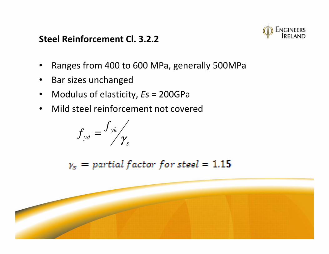
Steel Reinforcement Cl. 3.2.2
• Ranges from 400 to 600 MPa, generally 500MPa
• Bar sizes unchanged
• Modulus of elasticity, Es = 200GPa
• Mild steel reinforcement not covered
s
ykyd
ff
γ=

Section 4 Durability and Cover
Cl. 4.4.1.1 (2)
Cnom = Cmin + ΔCdev
Cmin = max{Cmin,b; Cmin,dur}
Cmin,b from Table 4.2 (generally bar size)
Cmin,dur from BS 8500 UK: IRISH N.A. & IS EN 206
ΔCdev = 10mm UK N. A.

Cover for Fire Protection
EN 1992-1-2 Typical dimensions / axis distance to satisfy fire resistance
Fire
Resistance
Beam One-way solid slab Braced column Simply
Supported
b min /a (mm)
Continuous
b min /a
(mm)
Simply
Supported
h min /a (mm)
Continuous
h min /a
(mm)
Exposed on
one side
b min /a
(mm)
Exposed on
more that one
side
b min /a (mm)
R60 120/40
160/35
200/30
300/25
120/25
200/12
80/20 80/10 155/25 250/46
350/40
R90 150/55
200/45
300/40
400/35
150/35
250/25
100/30 100/15 155/25 350/53
450/40
R120 200/65
240/65
300/55
500/50
200/45
300/35
450/35
500/30
120/40 200/20 175/35 350/57
450/51
R240 280/90
350/80
500/75
700/70
280/75
500/60
650/60
700/50
175/65 280/40 295/70
Notes
bmin, hmin= beam or column width
a = axis distance, generally distance to centre of reinforcing bar

Section 5 Structural Analysis
5.1.1 Common idealisations of the behaviour used for analysis
are:
• linear elastic behaviour (Cl. 5.4)
• linear elastic behaviour with limited redistribution (Cl. 5.5)
• plastic behaviour at ULS including strut and tie models (Cl. 5.6)
• non-linear behaviour (Cl. 5.7)
5.2 Geometric imperfections
Structure assumed to be out of plumb with
inclination of 1/200. Analysis must include an
equivalent horizontal load acting with the other
actions such as wind
5.8 second order effects with axial loads (columns)

5.1.3(1) permits analysis based on either:
(a) Alternate spans carrying the design
variable and permanent load , and
other spans carrying the permanent
load
(b) Any two adjacent spans carrying the
variable and permanent load, and all
other spans carrying only the design
permanent load
UK NA recommends (a), which leads
to three load cases considered
Load Cases and Combinations
Continuous Beams

Floor slab simplification
UK N.A. recommends
analysis based on all spans
loaded where:
(a) For one way spanning
slabs with bay areas > 30m2
(b) Ratio of variable to
permanent load ≤ 1.25
(c) Characteristic variable load
does not exceed 5 kN/m2
excluding partitions

NCCI: Concrete Centre: Concise Eurocode
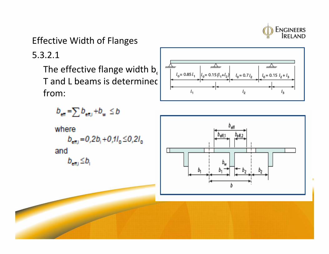
Effective Width of Flanges
5.3.2.1
The effective flange width beff for
T and L beams is determined
from:
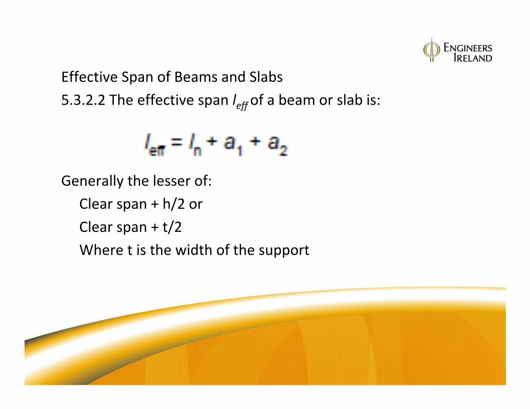
Effective Span of Beams and Slabs
5.3.2.2 The effective span leff of a beam or slab is:
Generally the lesser of:
Clear span + h/2 or
Clear span + t/2
Where t is the width of the support

Extract Figure 5.4
Section 6 Ultimate Limit State
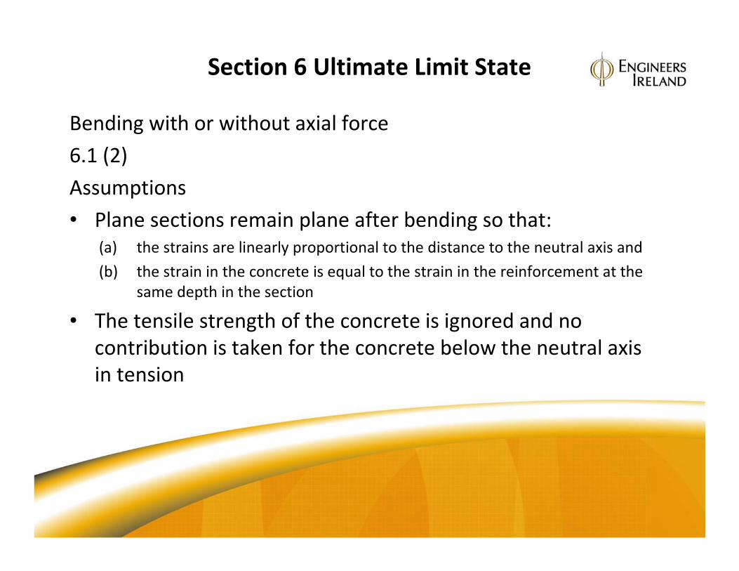
Bending with or without axial force
6.1 (2)
Assumptions
• Plane sections remain plane after bending so that:
(a) the strains are linearly proportional to the distance to the neutral axis and
(b) the strain in the concrete is equal to the strain in the reinforcement at the
same depth in the section
• The tensile strength of the concrete is ignored and no
contribution is taken for the concrete below the neutral axis
in tension

Strain distribution at ULS
Range of possible strain
distributions εcu2

6.1(2)P Stress in the reinforcement
• The stress in the
reinforcement is
derived from its stress-
strain curve given in
Figure 3.8
Es = 200 GPa
εuk = 0.05
Stress MPa
Strain
εud
Idealised design
curves
Where: ft = tensile strength of the reinforcement
fyk = yield strength of the reinforcement
Idealised
sydyd Ef=ε
Figure 3.8
0022.0
)15.1*3*200/(500
=
=
=
E
Ef sydydε
ydf
ykf

6.1 (3)P Stress in the concrete
• The ultimate strain in the concrete is
εcu2 = 0.0035 from
Table 3.1
• The stress in the concrete is obtained from the stress-strain curve Figure 3.3
Figure 3.3
c
ckf
γ
85.0
εc1 = 0.002 εcu = 0.0035
Stress MPa
Strain εcu2 = 0.0035 Strainεc2 = 0.002

Singly reinforced beams rectangular – parabolic stress
block
Neutral axis
x
εs
εcu2 = 0.0035
d
b
As
Strains at ULS
Figure 6.1
‘for use’
Concrete stress at
ULSSection
c
ckf
γ
85.0

EC2 Rectangular Stress Block Cl. 3.1.7 Figure 3.5
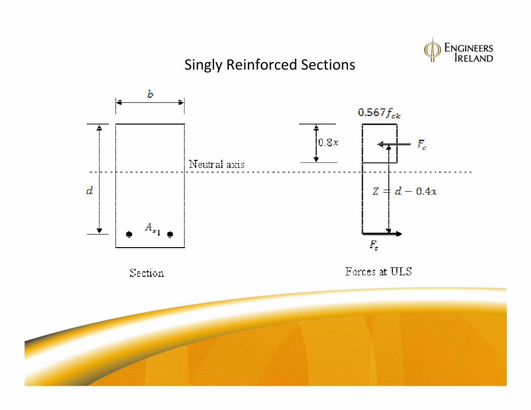
Singly Reinforced Sections

Design Equations
Moment of resistance based on concrete reaching ULS
for equilibrium at ULS REd MM =

Let
And let
Hence
Therefore
ck
Ed
fbd
Mk
2=
4.0
zdx
−=
2

Which is a quadratic equation in terms of With the positive roof of:
Which is an equation for the lever arm in terms of and
The area of steel reinforcement required to resist can be derived from:
With
Therefore:
Zf
MA
yk
Eds
87.0=
ZAf
ZFM s
m
yk
tEdγ
==

Summary: Design Equations
kZf
MA
yk
Eds
87.0=
ck
Ed
fbd
Mk
2=

Limit on kThese derived equations can be used to design the reinforcement in a singly
reinforced beam subject to the limits on the lever arm of:
1. Balanced design , which limits as a minimum
2. Maximum (5.6.3(2)), which limits as a minimum
These limits expressed in terms of k are:
1. Balanced design substitutes to give:
Which solves for maximum
2. Maximum
solves for maximum
It is also good practice to avoid failure by premature crushing of weak
concrete near the top of the section as a maximum

Doubly Reinforced Beams

For the EC2 limit the equilibrium of forces is:
Equation A
Equation B

By multiplying both sides of Equation A by and
rearranging gives
With
Equation C
Substitution of
into Equation B and Equation C converts them to
And
1

Shear
Section 6.2
• The strut inclination method is used for shear capacity checks
• The shear is resisted by concrete struts in compression and
shear reinforcement acting in tension
• Shear formulae expressed in terms of force rather than stress
• Designer free to choose a strut angle 22o ≤ θ ≤ 45o
BO1

Slide 38
BO1 Brian O'Rourke, 12/10/2009

Strut Inclination Method
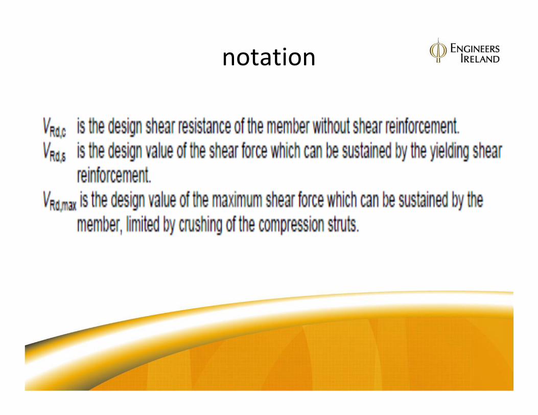
notation

Design equations are derived as follows:
The maximum design strength of the concrete strut
= Ultimate design strength x cross-sectional area
And its vertical component
this is the maximum vertical shear that can be resisted
by the concrete strut,
Trigonometrical conversion yields:

In EC2 this equation is modified by a strength
reduction, factor for concrete cracked in shear:
And
Therefore:

When the design shear force, exceeds
shear links must be provided.
Their area and spacing is obtained by taking a
method of sections cut at x-x
The vertical shear force in the link, is:
If the links are spaced at s then the force in each link
is proportionately:
The shear resistance must equal the shear
applied hence and by rearrangement:

EC2 minimum links are:
For minor members that do not require shear
reinforcement the shear capacity is given by an
empirical equation:
With a minimum value of:
Where
is taken from Figure 6.3 in EC2

Shear Formulae Summary
But not less than

Suggested Design Procedure for Shear1. Determine
2. Calculate the concrete compressive strut capacity for from:
3. If proceed to step 6
4. If check that the strut angle lies between 22o and 45o by
calculating
5. Determine the strut angle from:
6. Determine the area and spacing of the shear links from:
7. Check minimum links from:
8. Check link spacing maximum
9. Calculate additional longitudinal force in tension reinforcement.

Strut angle choice 220 - 450

Cl. 6.4 Punching Shear
• Basic control perimeter radius at corners
• Located at 2d form the face of the loaded area

Section 7 S.L.S.
The serviceability limit state of deflection can be checked using span-
effective depth ratios. A more rigorous approach is possible but is seldom
used in practice. the verification equation is:
Where:
Where:
N = Basic span-effective depth factor
K = Element typefactor
F1 = Flange beam factor
F2 = Brittle finishes factor
F3 = reinforcement stress factor
Cl. 7.4 SLS Deflection
≥


Columns
• Sections 5.8 & 6.1
• Design more complex than BS 8110
• Braced / Unbraced
• Geometric imperfections must be included in MEd
Procedure is to:
• Determine the slenderness ratio, λ
• Determine the limiting slenderness, λlim
• Design for axial load and first order moments
• Include for second order effects where they occur

Cl 5.8.3.2 Column Slenderness, λ
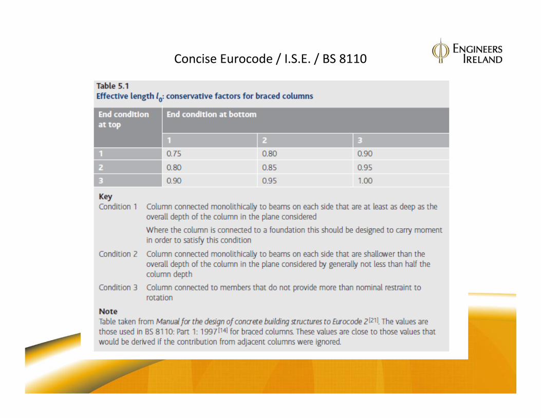
Concise Eurocode / I.S.E. / BS 8110

Limiting slenderness λlim
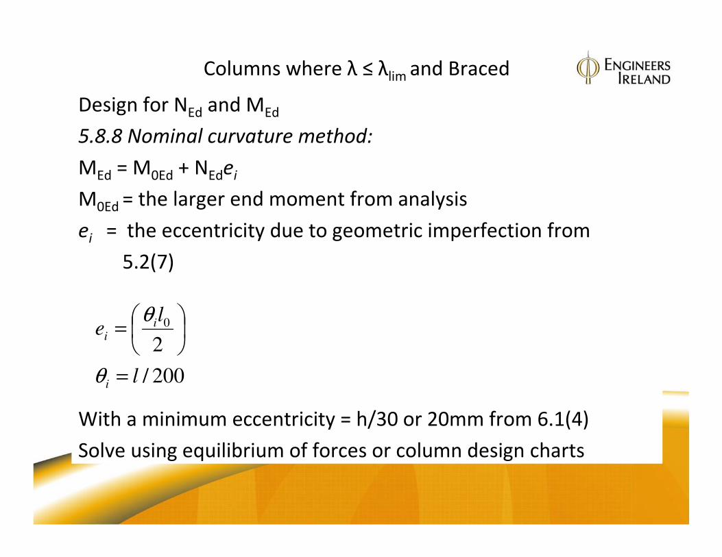
Columns where λ ≤ λlim and Braced
Design for NEd and MEd
5.8.8 Nominal curvature method:
MEd = M0Ed + NEdei
M0Ed = the larger end moment from analysis
ei = the eccentricity due to geometric imperfection from
5.2(7)
With a minimum eccentricity = h/30 or 20mm from 6.1(4)
Solve using equilibrium of forces or column design charts
200/
2
0
l
le
i
ii
=
=
θ
θ

Columns where λ ≥ λlim and Braced
Design for NEd and MEd
5.8.8 Nominal curvature method:
MEd = maximum of
(i) M02
(ii) M0Ed + M2
(iii) M01 +0.5M2
M0Ed is the equivalent first order moment
including the effect of imperfections at
about mid-span height of the column,
given as:
M0Ed = (0.6 M02 + 0.4M01)≥ 0.4M02 Exp 5.32
M2 is the nominal 2nd order moment, given
as :
M2 = NEd e2
e2= deflection curvature from Exp 5.33Again solve using equilibrium of forces
or column design charts

ULS Strain distribution Figure 6.1
for solution by equilibrium

Figure 6.1 column strain relationships

Column Design Charts: NCCI Concrete Centre / I.S.E

Column Design Example
Loading gk roof = 3.0 kN/m2 gk floor = 4.5 kN/m2
qk roof = 0.6 kN/m2 qk floor = 4.0 kN/m2
Main beams 600 mm deep x 300 mm wide
Other beams 400 mm deep x 300 mm wide
Columns 450 mm square
fck = 40 MPa fyk = 500 MPa
Assume pinned foundations and structure braced


