16 TRANSPORTATION RESEARCH RECORD 1118 Bridge Deck Expansion Joints SABIR H. DAHIR AND DALE B. MELLOTT The ability of a bridge deck expansion joint to be smooth riding, durable, and waterproof is essential to the performance of the bridge superstructure. Recent developments in the de- sign, manufacture, and installation procedures for expansion dam systems have indicated a potential ability to meet these requirements. In this study, the characteristics and field per- formance of modular expansion joint systems, metal-rein- forced elastomeric expansion dam systems, and gland-type bridge expansion dam systems were evaluated. Results of the field study are summarized and recommendations made on continued use of some systems, including neoprene seals for small movements (<2 in.), strip seals for intermediate move- ments (up to 4 in.), and finger dams with neoprene troughs for large movements (>4 in.). In 1984, the Pennsylvania Department of Transportation (PennDOT) entered into a cooperative agreement with the Federal Highway Administration (FHWA) to conduct a com- prehensive statewide evaluation of all types of bridge deck expansion joints used in Pennsylvania. Previous studies (1-4) conducted by the PennDOT on ex- pansion joint systems have revealed varied performance and snow plow damage. Increased deterioration was caused by chloride contamination that attacks the concrete and substruc- ture steel, and additional damage was caused by heavy truck traffic as the vehicle loads were transferred from one deck slab to the next. A recent study by the PennDOT's Operation Re- view Group revealed that 76 percent of the expansion joints were either completely open or leaking water onto the superstructure. This research effort has been directed to the evaluation of the performance capabilities of a variety of expansion joint sys- tems, including those of common and traditional specifications, ·as well as a number of recently developed systems. Several different proprietary and nonproprietary expansion joint types were reviewed and evaluated for their relative design, con- struction, and performance aspects. This repoi't covers the re- sults of the joint systems review and evaluation effort. SCOPE Bridge deck expansion joints are divided into the following three groups. 1. Modular expansion joint systems including finger and sliding plate dams, with 2 to 16 in. of movement, but generally more than 13 in. of movement. S. H. Dahir, Pennsylvania State University, Middletown, Pa. 17057. D. B. Mellott, Bureau of Bridge and Roadway Technology, Pennsyl- vania Department of Transportation, Harrisburg, Pa 17120. 2. Metal-reinforced expansion joint systems, with 1 1 /2 lo 13 in. of movement, but generally 2 to 13 in. of movement. 3. Strip seals and armored expansion joint systems, includ- ing preformed neoprene seals, with 1 /2 to 4 in. of movement. The bridge deck expansion joint systems that were evaluated in Pennsylvania are listed and abbreviated in this report as follows: 1. Modular expansion joints- ACMA Wabo-Maurer Delastiflex Finger dam AM WM DE FD 2. Metal-reinforced expansion joints- Transflex Waboflex Unidam Fel Span TF WF VD FS 3. Strip seal and armored expansion joints- ACMA AM Wabo-Maurer WM Delastiflex CP Onflex OF Pro Span PS Armored neoprene AR Preformed neoprene PN Strip seals SS Harris HS Most of these types have two or more models, depending on the movement width or modification of the initial design. Evaluating each joint type or system on at least three struc- tures in various parts of the state was proposed. An inventory and comprehensive information package available for evaluat- ing most of the systems was used to select the structures. A code universally used and accepted by engineers was provided to personnel by AASHTO. It is quoted here for ready reference: The design shall be such as to allow for total thermal movement at the rate of l1 /4 inches in 100 feet. Provisions shall be made for changes in length of span resulting from live load stresses. In spans more than 300 feet long, allowance shall be made for expansion and contraction in the floor. The expansion end shall be secured against lateral movement. It has been stipulated that a good expansion joint should
Transcript
16 TRANSPORTATION RESEARCH RECORD 1118
Bridge Deck Expansion Joints
SABIR H. DAHIR AND DALE B. MELLOTT
The ability of a bridge deck expansion joint to be smooth riding, durable, and waterproof is essential to the performance of the bridge superstructure. Recent developments in the design, manufacture, and installation procedures for expansion dam systems have indicated a potential ability to meet these requirements. In this study, the characteristics and field performance of modular expansion joint systems, metal-reinforced elastomeric expansion dam systems, and gland-type bridge expansion dam systems were evaluated. Results of the field study are summarized and recommendations made on continued use of some systems, including neoprene seals for small movements (<2 in.), strip seals for intermediate movements (up to 4 in.), and finger dams with neoprene troughs for large movements (>4 in.).
In 1984, the Pennsylvania Department of Transportation (PennDOT) entered into a cooperative agreement with the Federal Highway Administration (FHWA) to conduct a comprehensive statewide evaluation of all types of bridge deck expansion joints used in Pennsylvania.
Previous studies (1-4) conducted by the PennDOT on expansion joint systems have revealed varied performance and snow plow damage. Increased deterioration was caused by chloride contamination that attacks the concrete and substructure steel, and additional damage was caused by heavy truck traffic as the vehicle loads were transferred from one deck slab to the next. A recent study by the PennDOT's Operation Review Group revealed that 76 percent of the expansion joints were either completely open or leaking water onto the superstructure.
This research effort has been directed to the evaluation of the performance capabilities of a variety of expansion joint systems, including those of common and traditional specifications,
·as well as a number of recently developed systems. Several different proprietary and nonproprietary expansion joint types were reviewed and evaluated for their relative design, construction, and performance aspects. This repoi't covers the results of the joint systems review and evaluation effort.
SCOPE
Bridge deck expansion joints are divided into the following three groups.
1. Modular expansion joint systems including finger and sliding plate dams, with 2 to 16 in. of movement, but generally more than 13 in. of movement.
S. H. Dahir, Pennsylvania State University, Middletown, Pa. 17057. D. B. Mellott, Bureau of Bridge and Roadway Technology, Pennsylvania Department of Transportation, Harrisburg, Pa 17120.
2. Metal-reinforced expansion joint systems, with 11/2 lo 13 in. of movement, but generally 2 to 13 in. of movement.
3. Strip seals and armored expansion joint systems, including preformed neoprene seals, with 1/2 to 4 in. of movement.
The bridge deck expansion joint systems that were evaluated in Pennsylvania are listed and abbreviated in this report as follows:
1. Modular expansion joints-
ACMA Wabo-Maurer Delastiflex Finger dam
AM WM DE FD
2. Metal-reinforced expansion joints-
Transflex Waboflex Unidam Fel Span
TF WF VD FS
3. Strip seal and armored expansion joints-
ACMA AM Wabo-Maurer WM Delastiflex CP Onflex OF Pro Span PS Armored neoprene AR Preformed neoprene PN Strip seals SS Harris HS
Most of these types have two or more models, depending on the movement width or modification of the initial design.
Evaluating each joint type or system on at least three structures in various parts of the state was proposed. An inventory and comprehensive information package available for evaluating most of the systems was used to select the structures.
A code universally used and accepted by engineers was provided to personnel by AASHTO. It is quoted here for ready reference:
The design shall be such as to allow for total thermal movement at the rate of l1 /4 inches in 100 feet. Provisions shall be made for changes in length of span resulting from live load stresses. In spans more than 300 feet long, allowance shall be made for expansion and contraction in the floor. The expansion end shall be secured against lateral movement.
It has been stipulated that a good expansion joint should
Dahir and Mellott
1. Accommodate all movements of the structure, 2. Withstand all loadings, 3. Have good riding qualities, 4. Not present a danger to cyclists or other types of traffic, 5. Not impart undue stress to the structure unless the struc
ture has been designed accordingly, 6. Be reasonably silent and vibration free, 7. Give reliable service throughout the expected tempera
ture range, 8. Resist corrosion, 9. Facilitate maintenance and repair, and
10. Control deck drainage to prevent damage to structure below.
PROCEDURE
The bridge structures were selected from a listing of structures included in research work of the Bureau of Construction Quality Control ( 1, 3) and from a listing compiled by the Bureau of Bridge and Roadway Technology as the result of a request for bridge deck expansion systems used in the various engineering districts. FHWA supplied an evaluation form for joint ratings. The rating system was based on a scale of 5 (excellent) to 0 (failure) for each of the following joint parameters:
A. General appearance, B. Condition of anchorage, C. Debris accumulation, D. Watertightness, E. Surface damage, F. Noise under traffic, and G. Ease of maintenance.
Four engineers were chosen and worked in two-person teams to inspect and evaluate the joints on the selected structures using the FHWA rating system.
Rating joints for watertightness required inspecting below the joint under the bridge for evidence of water leakage. The teams performed this inspection wherever possible without elaborate arrangements. As a result, the teams were not able to evaluate this parameter on every installation. However, a sufficient number of the joint systems were inspected to reflect the degree of watertightness of the joint type of system.
One rating item was not clear to the inspection and rating team-namely, ease of maintenance. Strictly speaking, ease of maintenance is a characteristic of the joint design and construction. Therefore, it could not be adequately evaluated by the inspection team. Instead of ease of maintenance, the need for maintenance was rated. Accordingly, the rating figures shown under Item G on the performance record sheets reflect the degree to which the joint needed maintenance at the time of inspection.
The rating system proposed by FHWA was discussed by a project review team assembled explicitly for the purpose of reviewing and analyzing the data collected. The use of a weighted system was recommended based on the consideration of which items were most important relative to joint performance. These weighted rating factors were used to calculate
17
the final rating. The following weighted percentages were developed as the result of the voting by all the review team members.
Characteristic Percentage
General appearance Condition of anchorage Debris accumulation Watertightness Surface damage Noise under traffic Need for maintenance Total
9 26
9 27 12
8 9
100
Although bridge deck drainage was not considered as a part of the joint evaluation process, it was noted that in many cases lack of deck drainage maintenance may have contributed to joint problems. This needed maintenance was not included in the rating of the joints.
The PennDOT project review team reviewed the data, data analysis, and results of the study, and recommended improvements and refinements to the anchorage system and future rating procedures.
GENERAL DISCUSSION OF SYSTEMS EVALUATED
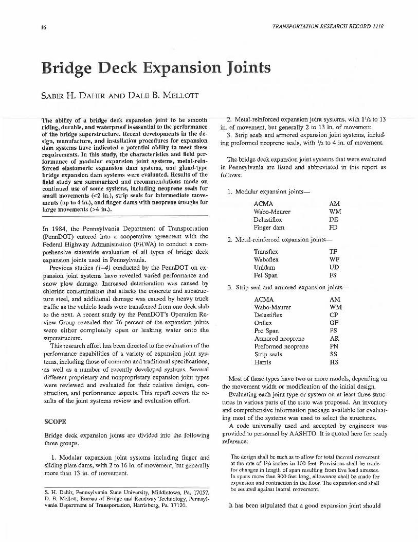
The inspection and evaluation teams collected data on 57 systems on 146 bridges throughout Pennsylvania. Schematic drawings typical of each system are listed in Figures 1--4.
Pennsylvania Standard Joint Systems
These systems basically consist of (a) open joints protected by armored neoprene or preformed neoprene compression seals, (b) metal plates with neoprene strips known as "strip seals" and anchored to the bridge deck, and (c) toothed bearing
TIE DOWN
., r -- ---'\,~ '-..DRAINAGE TROUGH
FIGURE 1 Typical finger dam and modular dam systems.
FIGURE 2 Typical metal-reinforced and continuous-belt dam systems.
.. . ·
. ,
llEQUIREO OPENING --
ARMOR--...,_
'
4
. ~-
....
~- COMPRESSION SEAL
f,
FIGURE 3 Typical conventional seal systems .
. ·• . ·. 0 . . . :r;; .. · . ., 0 .. . . .
. . > . t ... :'
... ' . f> . . 0 . .. . . . ·"
·~
~. (> .~ ~.~. ~: : : : ·~ · ;{)::'._~ .. :
FIGURE 4 Strip seal system.
supports (finger dams) to transmit traffic loads across the joints. The armored neoprene and standard unarmored neoprene compression seals are typically used with prestressed beam construction and are used for movements up to 2 in.; the strip seals are used for movements up to 4 in. The tooth, or finger, dams are used for movements exceeding 4 in., although they also may be used for movements of 4 in. or less. Figures 5-7
TRANSPORTATION RESEARCH RECORD 1118
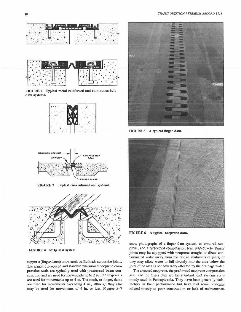
FIGURE 5 A typical finger dam.
FIGURE 6 A typical neoprene dam.
show photographs of a finger dam system, an armored neoprene, and a preformed compression seal, respectively. Finger joints may be equipped with neoprene troughs to direct contaminated water away from the bridge abutments or piers, or they may allow water to fall directly into the area below the joint if the area is not adversely affected by the drainage water.
The armored neoprene, the preformed neoprene compression seal, and the finger dam are the standard joint systems commonly used in Pennsylvania. They have been generally satisfactory in their performance but have had some problems related mostly to poor construction or lack of maintenance.
Dahir and Mellott
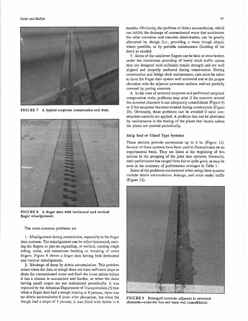
FIGURE 7 A typical neoprene compression seal dam.
FIGURE 8 A finger dam with horizontal and vertical finger misalignment.
The most common problems are
1. Misalignment during construction, especially in the finger dam systems. The misalignment can be either horizontal, causing the fingers to jam on expanding, or vertical, causing rough riding, noise, and sometimes bending or breaking of some fingers. Figure 8 shows a finger dam having both horizontal and vertical misalignment.
2. Blockage of dams by debris accumulation. This problem arises when the dam or trough does not have sufficient slope to drain the contaminated water and flush the loose debris before it has a chance to accumulate and harden, or when the dams having small slopes are not maintained periodically. It was reported by the Arkansas Department of Transportation (5) that when a finger dam had a trough sloping at 8 percent, there was no debris accumulation 6 years after placement, but when the trough had a slope of 1 percent, it was filled with debris in 6
19
months. Obviously, the problem of debris accumulation, which can inhibit the drainage of contaminated water that accelerates the rebar corrosion and concrete deterioration, can be greatly alleviated by design (i.e., providing a steep trough slope), where possible, or by periodic maintenance (flushing of the dam) as needed.
3. Some of the cantilever fingers can be bent or even broken under the continuous pounding of heavy truck traffic unless they are designed with sufficient tensile strength and are well aligned and properly anchored during construction. During construction and bridge deck maintenance, care must be taken to have the finger dam system well anchored and at the proper elevation with the adjacent pavement surface, and not partially covered by paving concrete.
4. In the case of armored neoprene and preformed neoprene compression seals, problems may arise if the concrete around the armored channels is not adequately consolidated (Figure 9) or if the neoprene becomes twisted during construction (Figure 10). Obviously, these problems can be avoided if strict construction controls are applied. A problem that can be alleviated by maintenance is the rusting of the plates that occurs unless the plates are painted periodically.
Strip Seal or Gland Type Systems
These devices provide movements up to 4 in. (Figure 11). Several of these systems have been used in Pennsylvania on an experimental basis. They are listed at the beginning of this section in the grouping of the joint dam systems. Generally, their performance has ranged from fair to quite good, as may be seen in the summary of performance averages in Table 1.
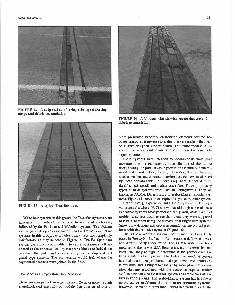
Some of the problems encountered when using these systems include debris accumulation, leakage, and noise under traffic (Figure 12).
FIGURE 9 Damaged concrete adjacent to armored channels---concrete has not been well consolidated.
20 TRANSPORTATION RESEARCH RECORD 1118
TABLE 1 SUMMARY OF RATINGS BY JOINT SYSTEM TYPE
Condition Unadjusted Weighted Model Name No. A B c D E F G Avg Avg
Norn: Ratings were as follows: poor, <3 .50; fair, 3.50--3.84; satisfactory, 3.85-4.19; good, 4.20-4.59; excellent, >4.60.
Metal-Reinforced Elastomeric and Continuous-Belt Dam Systems
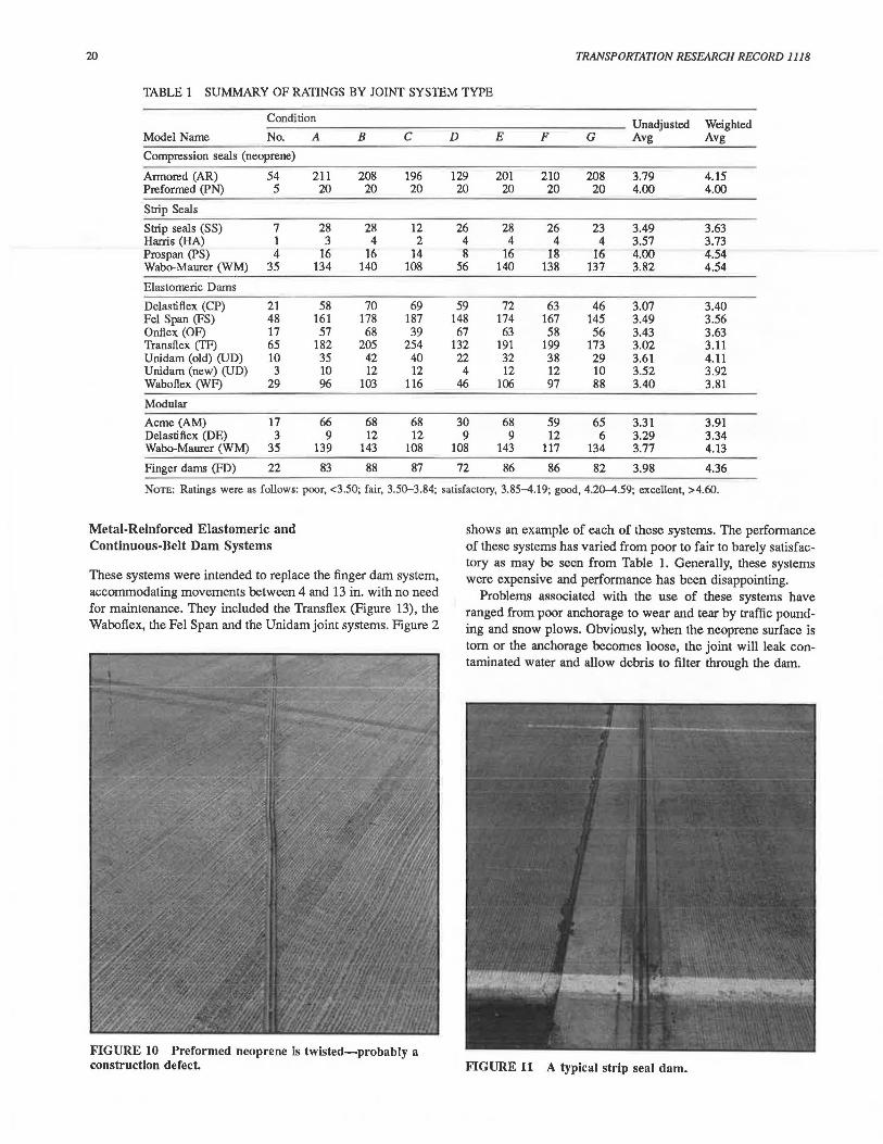
These systems were intended to replace the finger dam system, accommodating movements between 4 and 13 in. with no need for maintenance. They included the Transflex (Figure 13), the Waboflex, the Fel Span and the Unidam joint systems. Figure 2
FIGURE 10 Preformed neoprene ls twisted-probably a construction defect.
shows an example of each of these systems. The performance of these systems has varied from poor to fair to barely satisfac-tory as may be seen from Table 1. Generally, these systems were expensive and performance has been disappointing.
Problems associated with the use of these systems have ranged from poor anchorage to wear and tear by traffic pound-ing and snow plows. Obviously, when the neoprene surface is tom or the anchorage becomes loose, the joint will leak con-taminated water and allow debris to filter through the dam.
FIGURE 11 A typical strip seal dam.
Dahir and Mellott
FIGURE 12 A strip seal dam having missing reinforcing strips and debris accumulation.
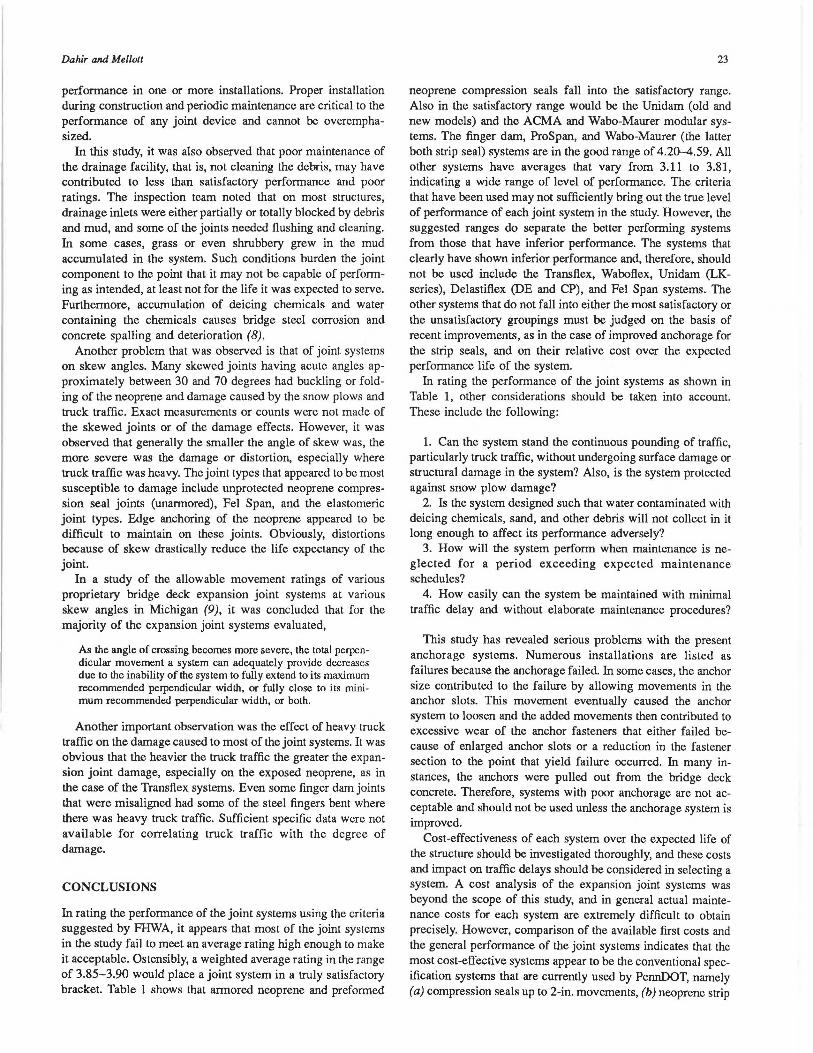
FIGURE 13 A typical Transflex dam.
Of the four systems in this group, the Transflex systems were generally most subject to tear and loosening of anchorage, followed by the Fel Span and Waboflex systems. The Unidam system generally performed better than the Transflex and other systems in this group; nevertheless, they were not completely satisfactory, as may be seen in Figure 14. The Fel Span dam system has since been modified to use a continuous belt anchored to the concrete deck by neoprene blocks or hold-down members that put it in the same group as the strip seal and gland type systems. The old version would leak where the segmented sections were joined in the field.
The Modular Expansion Dam Systems
These systems provide movements up to 26 in. or more through a prefabricated assembly or module that consists of one or
21
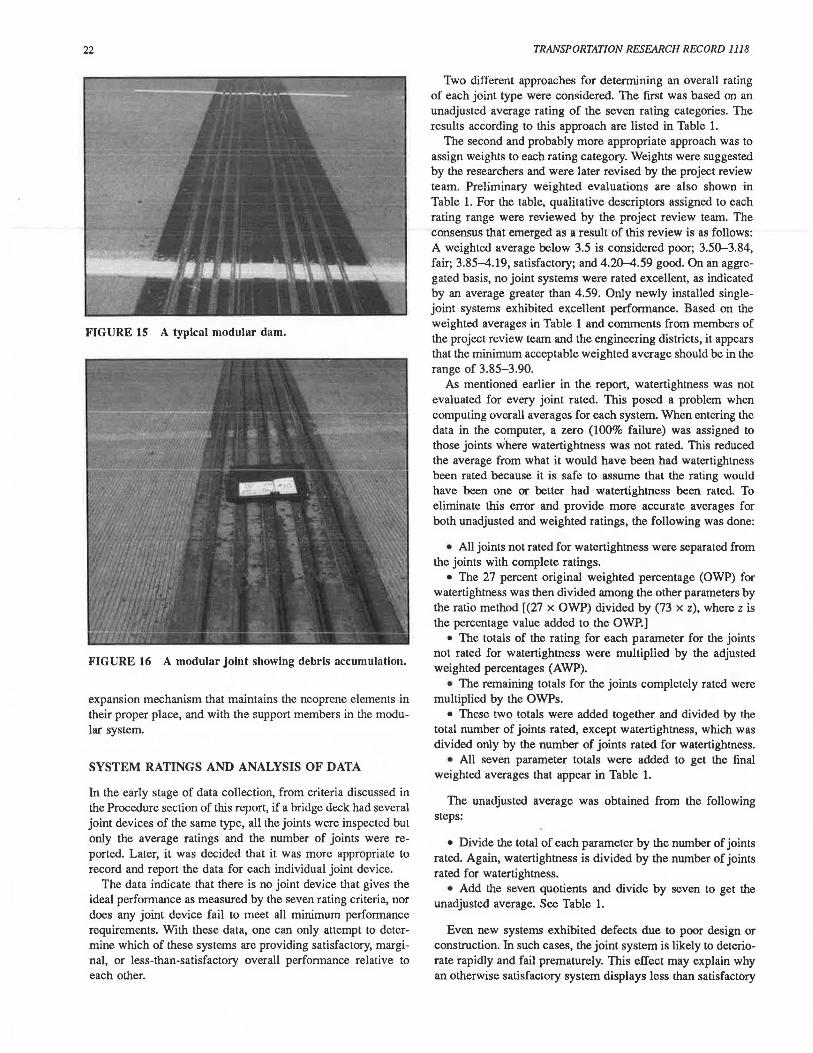
FIGURE 14 A Unldam joint showing severe damage and debris accumulation.
more preformed neoprene elastomeric elements secured between contoured transverse load distribution members that bear on custom-designed support beams. The entire module is installed between end dams anchored into the concrete superstructure.
These systems were intended to accommodate wide joint movements while permanently (over the life of the bridge deck) sealing the joints so as to prevent infiltration of contaminated water and debris, thereby alleviating the problems of steel corrosion and concrete deterioration that are accelerated by these contaminants. In short, they were supposed to be durable, leak proof, and maintenance free. Three proprietary types of these systems were used in Pennsylvania. They are known as ACMA, Delastifiex, and Wabo-Maurer modular systems. Figure 15 shows an example of a typical modular system.
Unfortunately, experience with these systems in Pennsylvania and elsewhere (6, 7) shows that although some of these expensive systems have performed fairly well, most have had problems, no less troublesome than those they were supposed to eliminate when using the conventional finger dam systems. Snow plow damage and debris accumulation are typical problems with the modular systems (Figure 16).
The ACMA modular system performance has been fairly good in Pennsylvania, but it often becomes deformed, leaks, and is fairly noisy under traffic. The ACMA system has been modified to the new ACMA Beta series, but this series has not been used long enough to determine if the performance has been substantially improved. The Delastiflex modular system has had anchorage problems, leakage, noise, and debris accwnulation, and is subject to damage by snow plows. The snow plow damage associated with the excessive exposed rubber surface has made the Delastiflex system unsuitable for installation in Pennsylvania. The Wabo-Maurer system has had fewer performance problems than the other modular systems; however, the Wabo-Maurer modular has had problems with the
22
FIGURE 15 A typical modular dam.
FIGURE 16 A modular joint showing debris accumulation.
expansion mechanism that maintains the neoprene elements in their proper place, and with the support members in the modular system.
SYSTEM RATINGS AND ANALYSIS OF DATA
In the early stage of data collection, from criteria discussed in the Procedure section of this report, if a bridge deck had several joint devices of the same type, all the joints were inspected but only the average ratings and the number of joints were reported. Later, it was decided that it was more appropriate to record and report the data for each individual joint device.
The data indicate that there is no joint device that gives the ideal performance as measured by the seven rating criteria, nor does any joint device fail to meet all minimum performance requirements. With these data, one can only attempt to determine which of these systems are providing satisfactory, marginal, or less-than-satisfactory overall performance relative to each other.
TRANSPORTATION RESEARCH RECORD 1118
Two different approaches for determining an overall rating of each joint type were considered. The first was based on an unadjusted average rating of the seven rating categories. The results according to this approach are listed in Table 1.
The second and probably more appropriate approach was to assign weights to each rating category. Weights were suggested by the researchers and were later revised by the project review team. Preliminary weighted evaluations are also shown in Table 1. For the table, qualitative descriptors assigned to each rating range were reviewed by the project review team. The consensus that emerged as a result of this review is as follows: A weighted average below 3.5 is considered poor; 3.50-3.84, fair; 3.85-4.19, satisfactory; and 4.20--4.59 good. On an aggregated basis, no joint systems were rated excellent, as indicated by an average greater than 4.59. Only newly installed singlejoint systems exhibited excellent performance. Based on the weighted averages in Table 1 and comments from members of the project review team and the engineering districts, it appears that the minimum acceptable weighted average should be in the range of 3.85-3.90.
As mentioned earlier in the report, watertightness was not evaluated for every joint rated. This posed a problem when computing overall averages for each system. When entering the data in the computer, a zero (100% failure) was assigned to those joints where watertightness was not rated. This reduced the average from what it would have been had watertightness been rated because it is safe to assume that the rating would have been one or better had watertightness been rated. To eliminate this error and provide more accurate averages for both unadjusted and weighted ratings, the following was done:
• All joints not rated for watertightness were separated from the joints with complete ratings.
• The 27 percent original weighted percentage (OWP) for watertightness was then divided among the other parameters by the ratio method ((27 x OWP) divided by (73 x z), where z is the percentage value added to the OWP.]
• The totals of the rating for each parameter for the joints not rated for watertightness were multiplied by the adjusted weighted percentages (AWP).
• The remaining totals for the joints completely rated were multiplied by the OWPs.
• These two totals were added together and divided by the total number of joints rated, except watertightness, which was divided only by the number of joints rated for watertightness.
• All seven parameter totals were added to get the final weighted averages that appear in Table 1.
The unadjusted average was obtained from the following steps:
• Divide the total of each parameter by the number of joints rated. Again, watertightness is divided by the number of joints rated for watertightness.
• Add the seven quotients and divide by seven to get the unadjusted average. See Table 1.
Even new systems exhibited defects due to poor design or construction. In such cases, the joint system is likely to deteriorate rapidly and fail prematurely. This effect may explain why an otherwise satisfactory system displays less than satisfactory
Dahir and Mellott
performance in one or more installations. Proper installation during construction and periodic maintenance are critical to the performance of any joint device and cannot be overemphasized.
In this study, it was also observed that poor maintenance of the drainage facility, that is, not cleaning the debris, may have contributed to less than satisfactory performance and poor ratings. The inspection team noted that on most structures, drainage inlets were either partially or totally blocked by debris and mud, and some of the joints needed flushing and cleaning. In some cases, grass or even shrubbery grew in the mud accumulated in the system. Such conditions burden the joint component to the point that it may not be capable of performing as intended, at least not for the life it was expected to serve. Furthermore, accumulation of deicing chemicals and water containing the chemicals causes bridge steel corrosion and concrete spalling and deterioration (8).
Another problem that was observed is that of joint systems on skew angles. Many skewed joints having acute angles approximately between 30 and 70 degrees had buckling or folding of the neoprene and damage caused by the snow plows and truck traffic. Exact measurements or counts were not made of the skewed joints or of the damage effects. However, it was observed that generally the smaller the angle of skew was, the more severe was the damage or distortion, especially where truck traffic was heavy. The joint types that appeared to be most susceptible to damage include unprotected neoprene compression seal joints (unarmored), Fel Span, and the elastomeric joint types. Edge anchoring of the neoprene appeared to be difficult to maintain on these joints. Obviously, distortions because of skew drastically reduce the life expectancy of the joint.
In a study of the allowable movement ratings of various proprietary bridge deck expansion joint systems at various skew angles in Michigan (9), it was concluded that for the majority of the expansion joint systems evaluated,
As the angle of crossing becomes more severe, the total perpendicular movement a system can adequately provide decreases due to the inability of the system to fully extend to its maximum recorrunended perpendicular width, or fully close to its minimum recommended perpendicular width, or both.
Another important observation was the effect of heavy truck traffic on the damage caused to most of the joint systems. It was obvious that the heavier the truck traffic the greater the expansion joint damage, especially on the exposed neoprene, as in the case of the Transftex systems. Even some finger dam joints that were misaligned had some of the steel fingers bent where there was heavy truck traffic. Sufficient specific data were not available for correlating truck traffic with the degree of damage.
CONCLUSIONS
In rating the performance of the joint systems using the criteria suggested by FHWA, it appears that most of the joint systems in the study fail to meet an average rating high enough to make it acceptable. Ostensibly, a weighted average rating in the range of 3.85-3.90 would place a joint system in a truly satisfactory bracket. Table 1 shows that armored neoprene and preformed
23
neoprene compression seals fall into the satisfactory range. Also in the satisfactory range would be the Unidam (old and new models) and the ACMA and Wabo-Maurer modular systems. The finger dam, ProSpan, and Wabo-Maurer (the latter both strip seal) systems are in the good range of 4.20--4.59. All other systems have averages that vary from 3.11 to 3.81, indicating a wide range of level of performance. The criteria that have been used may not sufficiently bring out the true level of performance of each joint system in the study. However, the suggested ranges do separate the better performing systems from those that have inferior performance. The systems that clearly have shown inferior performance and, therefore, should not be used include the Transftex, Waboftex, Unidam (LKseries), Delastiftex (DE and CP), and Fel Span systems. The other systems that do not fall into either the most satisfactory or the unsatisfactory groupings must be judged on the basis of recent improvements, as in the case of improved anchorage for the strip seals, and on their relative cost over the expected performance life of the system.
In rating the performance of the joint systems as shown in Table 1, other considerations should be taken into account. These include the following:
1. Can the system stand the continuous pounding of traffic, particularly truck traffic, without undergoing surface damage or structural damage in the system? Also, is the system protected against snow plow damage?
2. Is the system designed such that water contaminated with deicing chemicals, sand, and other debris will not collect in it long enough to affect its performance adversely?
3. How will the system perform when maintenance is neglected for a period exceeding expected maintenance schedules?
4. How easily can the system be maintained with minimal traffic delay and without elaborate maintenance procedures?
This study has revealed serious problems with the present anchorage systems. Numerous installations are listed as failures because the anchorage failed. In some cases, the anchor size contributed to the failure by allowing movements in the anchor slots. This movement eventually caused the anchor system to loosen and the added movements then contributed to excessive wear of the anchor fasteners that either failed because of enlarged anchor slots or a reduction in the fastener section to the point that yield failure occurred. In many instances, the anchors were pulled out from the bridge deck concrete. Therefore, systems with poor anchorage are not acceptable and should not be used unless the anchorage system is improved.
Cost-effectiveness of each system over the expected life of the structure should be investigated thoroughly, and these costs and impact on traffic delays should be considered in selecting a system. A cost analysis of the expansion joint systems was beyond the scope of this study, and in general actual maintenance costs for each system are extremely difficult to obtain precisely. However, comparison of the available first costs and the general performance of the joint systems indicates that the most cost-effective systems appear to be the conventional specification systems that are currently used by PennDOT, namely (a) compression seals up to 2-in. movements, (b) neoprene strip
24
seals with improved anchorage up to 4-in. movements, and (c) finger dams for movement greater than 4 in. The survey teams observed that these systems had the least damage occurrence and the least need for maintenance.
RECOMMENDATIONS
Until better maintenance-free systems or procedures are found, it is recommended that the joint systems to be implemented should be only those systems that have a weighted average rating of 3.85 or more, or have been found highly satisfactory by the engineering districts. Of these systems, preference should be given where possible to those with the least need for maintenance and to those that can be maintained easily. Systems with a satisfactory rating of 3.85 or more may be used selectively where conditions and cost justify their use, provided that improvements on weaknesses are made where possible and strict adherence to installation details during construction is observed. Obviously, joint systems with ratings of poor and fair (less than 3.85) should not be used.
Furthermore, until a system is developed that would require minimal maintenance, a maintenance schedule should be established to include periodic maintenance of the bridge deck drainage system and cleaning of the expansion joint system. Even with the present systems, scheduling of bridge deck maintenance is just as important as roadway joint sealing or roadside mowing of the grass. This maintenance schedule should be included as a part of the bridge deck expansion joint system requirements at the outset, that is, when the system is installed. Thus far, there appears to be no perfect, truly maintenance-free expansion joint system, especially for the larger movements. Like most other systems, without proper maintenance these systems will not meet all the requirements they are designed to achieve. Maintenance costs over the life of the system, including traffic delays, should be included when comparing service life costs of the systems. As previously stated, strict adherence to installation detail is of paramount importance for both the proper function of the system and reduced maintenance costs.
The presence of anchor-related modes of failure suggests that the anchors should be cast as a part of the concrete construction and securely fastened to the reinforcement steei in the concrete. The problem can be directly attributed to a design that did not use the proper size of anchor or the failure to require the proper securing of the anchor, that is, locking devices were not used or the bolt torque requirement was not correct. These deficiencies should be corrected by proof load testing or by using adhesive anchors.
Manufacturer's designs and PennDOT's specified designs for expansion joint systems need to be improved with regard to performance. Systems whose performance is decreased greatly by small deviations from ideal or design installation techniques should be identified and improved, or their use should be prohibited.
TRANSPORTATION RESEARCH RECORD 1118
ACKNOWLEDGMENTS
This project was sponsored in part by FHWA under Special Experimental Features Program, Experimental Project No. 5, "Bridge Deck Expansion Joints" in cooperation with PennDOT.
The evaluation was conducted under the general supervision of the project manager Gerald J. Malaskeskie. The evaluation study and report editing were completed with the assistance of K. A. McManigle and J. L. Williams, civil engineers assigned to the Bureau of Bridge and Roadway Technology. One of the latter served on each of the two evaluation teams that conducted the actual inspection and evaluation of the bridge deck expansion joints. Members of the project review team who assisted in the evaluation process are the following PennDOT professional engine.ers: R. McClure, F. Sankey, W. Scott, J. Ebersole, C. Reed, D. Casner, H. Wels, G. Dorsch, and S. Dadhania.
REFERENCES
1. D. B. Mellott. Transflex Bridge Expansion Joints. Research Project 69-23. Pennsylvania Department of Transportation, Harrisburg, March 1970.
2. R. J. Brunner and D. B. Mellott. A Summary Report on the Installation and Performance of Pavement and Bridge Joint Sealants. Pennsylvania Department of Transportation, Harrisburg, Nov. 1973.
3. D. B. Mellott. Transflex Bridge Expansion Joints. Research Project 69-23. Final Report. Pennsylvania Department of Transportation, Harrisburg, Nov. 1977.
4. D. B. Mellott. Status of Bridge Deck Expansion Dam Systems. Research Projects 73-15, 73-16, and 74-20; Pennsylvania Department of Transportation, Harrisburg, Nov. 1978.
5. ASSHTO Design Practices, Standard Specifications for Highway Bridges. 11th ed., AASHTO, Washington, D.C., 1973, p. 128.
6. Watertight Bridge Deck Joint Seals. National Experimental and Evaluation Program, Final Report, Project 11, FHWA, U.S. Department of Transportation, July 1977.
7. Bridge Inspection and Rehabilitation. Transportation Research Record 899, TRB, National Research Council, Washington, D.C., 1983, 76 pp.
8. Departmental Bridge Maintenance-1985. Operations Review, Pennsylvania Department of Transportation, Harrisburg, Nov. 1985.
9. F. J. Bashore, A. W. Price, and D. E. Branch. Determination of Allowable Ratings for Various Proprietary Bridge Deck Expansion Joint Devices at Various Skew Angles. Michigan Transportation Commission, Lansing, Mich., May 1980.
This work was primarily sponsored by PennDOT. The contents of this paper reflect the views of the authors, who are responsible/or the facts and accuracy of the data presented herein. The contents do not necessarily reflect the official views or the policies of the stale of Pennsylvania or of the FHWA. This paper does not constitute a standard, specification, or regulation. PennDOT does not endorse products, equipment, processes, or manufacturers. Trademarks or manufacturers' names appear herein only because they are considered essential.
Publication of this paper sponsored by Commillee on General Structures.