please read firstThis operating manual provides important information on the handling of the unit. It is an integral part of the product and must be stored so that it is accessible in the immediate vicinity of the unit. It must remain available throughout the entire service life of the unit. It must be handed over to subsequent owners or users of the unit.
Read the operating manual before working on or operating the unit. This applies in particular to the chapter on safety. Always follow all instructions completely and without restrictions.
It is possible that this operating manual may contain instructions that seem incomprehensible or unclear. In the event of any questions or if any details are unclear, contact the factory customer service department or the manufacturer’s local partner.
Since this operating manual was written for several different models of the unit, always comply with the parameters for the respective model.
This operating manual is intended only for persons assigned to work on or operate the unit. Treat all constituent parts confidentially. The information contained herein is protected by copyright. No part of this manual may be reproduced, transmitted, copied, stored in electronic data systems or translated into another language, either wholly or in part, without the express written permission of the manufacturer.
symbolsThe following symbols are used in the operating manual. They have the following meaning:
Information for operators.
Information or instructions for qualified technicians.
Danger! Indicates a direct impending danger
resulting in severe injuries or death.
WarnIng! Indicates a potentially dangerous situation
that could result in serious injuries or death.
CautIon! Indicates a potentially dangerous situation
that could result in medium or slight injuries.
CautIon! Indicates a potentially dangerous situation,
which could result in property damage.
note. emphasised information.
€ energy savIng tIp Indicates suggestions that help to save
energy, raw materials and costs.
Reference to other sections of the operating manual.
Reference to other instructions of the manufacturer.
AUfSTellUNG UNd moNTAGe ...........................................8Aufstellungsraum ..................................................................8Transport zum Aufstellungsort ..........................................9Aufstellung ...........................................................................10einbau der modulbox ......................................................... 11montage der hydraulischen Anschlüsse ..........................12öffnen der eckkugelhähne an der modulbox .................15Sicherheitsbaugruppe .........................................................15Ausdehungsgefässe .............................................................15
SpüleN UNd BefülleN deR ANlAGe ............................18Spülen und befüllen der Wärmequelle ............................18Spülen und befüllen des Heiz- und
Brauchwarmwasserladekreises ..................................19Spülen, befüllen und entlüften des
eNTlüfTeN ..............................................................................20entlüften der modulbox .....................................................20entlüften der Umwälzpume der Wärmequelle ..............20prüfen und einstellen des überströmventils ..................21
moNTAGe deS BedIeNTeIlS ..............................................22
mASSBIldeR UNd ABSTANdSmASSemaßbilder .............................................................................34Abstandsmaße .....................................................................35
intended useThe unit may be used only for the intended purpose. This means:
• for heating.
• for domestic water heating.
• in frost-free buildings
The unit may be operated only within its technical parameters.
overview “Technical data / scope of delivery”.
note. notify the responsible power supply
company of the use of a heat pump or heat pump system.
DisclaimerThe manufacturer is not liable for losses resulting from any use of the unit which is not its intended use.
The manufacturer’s liability also expires:
• if work is carried out on the unit and its components contrary to the instructions in this operating manual.
•if work is improperly carried out on the unit and its components.
• if work is carried out on the unit which is not described in this operating manual, and this work has not been explicitly approved by the manufacturer in writing.
• if the unit or components in the unit have been altered, modified or removed without the explicit written consent of the manufacturer.
eC conformityThe unit bears the ce mark of conformity.
ec declaration of conformity
safetyThe unit is safe to operate for its intended use. The construction and design of the unit conform to current state of the art standards, all relevant regulations and all relevant safety regulations.
every person who performs work on the unit must have read and understood the operating manual prior to starting any work. This also applies if the respective person has already worked with such a unit or a similar unit or has been trained by the manufacturer.
every person who performs work on the unit must comply with the applicable accident prevention and safety regulations. This applies in particular to the wearing of personal protective equipment.
Danger! risk of fatal injury due to electric shock! electrical connections may be installed
only by qualified electricians.
Before opening the unit, disconnect the system from the power supply and secure it from being switched back on!
Danger! only qualified technicians (trained
heating, cooling, refrigerant and electrical technicians) may perform work on the unit and its components.
WarnIng! observe safety labels on and in the unit.
WarnIng! unit contains refrigerants! Leaking refrigerant could result in
personal injury or material damage. therefore:
– shut down unit.– ventilate installation location– notify the manufacturer’s authorised
service centre.
CautIon! For safety reasons: never disconnect the unit from the power
Customer servicefor technical information please contact a qualified technician or the manufacturer’s local partner.
overview “customer service”.
Warranty / Guaranteefor warranty and guarantee conditions, please refer to the purchase documents.
note. please contact your dealer concerning
warranties and guarantees.
DisposalWhen decommissioning the unit, always comply with applicable laws, directives and standards for the recovery, recycling and disposal of materials and components of cooling units.
Heat pumps operate on the same principle as a refrigerator: same technology, only with reversed benefits. The refrigerator extracts heat from foods, which is released into the room through fins on the back.
The heat pump extracts heat from our environment: air, earth or ground water. The extracted heat is conditioned in the unit and supplied to the heating water. even when it is extremely cold outside, the heat pump draws enough heat to heat a house.
example: drawing of a brine/water heat pump with underfloor heating:
area of utilisationTaking into consideration the ambient conditions, limits of application and the applicable regulations, every heat pump can be utilised in new or existing heating systems.
overview “Technical data / scope of delivery”.
OperationYour decision to purchase a heat pump or a heat pump system is a long-term contribution to protecting the environment through low emissions and reduced primary energy use.
You can operate and control the heat pump system with the control element of the heating and heat pump regulator.
note. Make sure that the control settings are
correct.
operating manual of the heating and heat pump regulator.
To ensure that your heat pump or heat pump system operates efficiently and ecologically, the following are especially important:
€ energy savIng tIp avoid unnecessarily high flow tempera-
tures. a lower flow temperature on the hot
water side increases the efficiency of the system.
€ energy savIng tIp When letting in fresh air, do not leave
windows open for an extended period, in order to save energy and reduce your heating costs.
Care of the unitThe outer surfaces of the unit can be cleaned with a damp cloth and household cleaning products.
do not use cleaning or care products that contain abrasives, acids and/or chlorine. Such products would destroy the surfaces and could also damage the technical components of the unit.
maintenance of the unitThe cooling circuit of the heat pump requires no regular maintenance.
According to eU regulation (ec) 842/2006 of may 17, 2006, leak inspections and maintenance of a log book are required for certain heat pumps!
The criteria for conducting leak inspections and maintaining a log book are based on the hermetic impermeability of the cooling circuit and the refrigerant capacity of the heat pump! No log book is required for heat pumps with a refrigerant capacity of < 3kg. With all other heat pumps, the log book is included with all other delivered materials.
log book for heat pumps, Section “Information on use of the log book”.
The components of the heating circuit and the heat source (valves, expansion vessels, circulating pumps, filters, dirt traps) should be inspected as well as cleaned as needed - at the very least annually - by a qualified heating or cooling system technician.
Regularly check that the safety valve for the domestic hot water tank is in proper working order.
It is a good idea to have a maintenance contract with a heating installation company. The company will conduct all required maintenance at regular intervals.
CleaningandflushingofunitComponents
CautIon! unit components may be cleaned
and flushed only by customer service personnel authorised by the manufacturer. use only liquids recommended by the manufacturer.
Flushing of the liquefier with chemical cleaning agents must be followed by neutralisation of residue and intensive flushing with water. always observe the technical data of the manufacturer of the heat exchanger.
malfunctionsIn the event of a malfunction, you can detect the cause of the malfunction via the diagnostic program of the heating and heat pump regulator.
operating manual of the heating and heat pump regulator.
WarnIng! service and repair work on the
components of the unit may be performed only by customer service personnel authorised by the manufacturer.
overview “customer service”.
Note that no malfunction is displayed if the safety temperature limiter on the electric heating element has been triggered.
“commissioning”, “Safety temperature limiter” section.
To avoid damage during transport, you should transport the unit to the final installation location (secured on a wooden pallet) using a lifting truck.
If it is not possible to transport the unit to the final installation location using a lifting truck, you can also transport the unit using a hand truck.
WarnIng! several people are required to transport
the unit. Do not underestimate the weight of the units.
overview “Technical data / scope of delivery”, “General unit data” section.
CautIon! Wear safety gloves.
WarnIng! unit is not fastened to the wooden pallet.
the unit can tip when being lifted down and during transport with a hand truck. this can result in personal injury and damage to the unit.
– take suitable precautions to prevent the risk of tipping over.
proceed as follows if transport with a lifting truck is not possible:
Remove packaging and transport material. Remove extra box and module box from the wooden pallet and bring to installation location.
Use straps to lift and carry the module box.
CautIon! Do not tilt the module box more than a
maximum of 45° (in any direction).
CautIon! never use components, pipes of the
cooling circuit or hydraulic connections on the module box for transport purposes.
CautIon! Do not damage the hydraulic connections
under any circumstances.
dispose of angle bracket, transport and packaging material properly and in accordance with ecological principles.
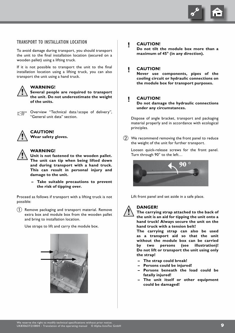
We recommend removing the front panel to reduce the weight of the unit for further transport.
loosen quick-release screws for the front panel. Turn through 90° to the left…
lift front panel and set aside in a safe place.
Danger! the carrying strap attached to the back of
the unit is an aid for tipping the unit onto a hand truck! always secure the unit on the hand truck with a tension belt!
the carrying strap can also be used as a transport aid so that the unit without the module box can be carried by two persons (see illustration)! Do not lift or transport the unit using only the strap!
– the strap could break!– persons could be injured!– persons beneath the load could be
fatally injured! – the unit itself or other equipment
Slowly and carefully tip the unit back into the original position.
•
Repeat procedure on the other side of the unit.
place unit at final installation location. compensate for minor unevenness using the four adjusting screws. Then tighten the lock nuts.
installationofthemodulebox
The entire cooling circuit of the heat station is contained in the module box.
CautIon! Do not tilt the module box more than a
maximum of 45° (in any direction).
place module box in front of the unit.
1 Unit2 plug for electrical connection3 front edge of bottom of unit4 module box
Use straps to lift module box and initially place in unit so that the rubber feet of the module box that are facing the unit come to rest on the centring plate behind the front edger of the bottom of the unit.
push module box into the unit until the front rubber foot of the module box contacts the front edge of the bottom of the unit and has to be lifted over it.
When pushing in the box, make sure that the plugs for the electrical connection are not pinched and damaged.
Raise module box, push it further into the unit and lower the box as soon as the rubber feet contact the corresponding stops of the centring plate.
Set the front left rubber foot of the module box between the guide elements.
The module box is positioned correctly in the unit when the rubber feed are placed as shown in the following sketch:
1 Stops on centring plate2 Rear rubber feet of module box3 centring plate for module
box on bottom of unit4 front rubber feet of module box5 Guide element
constructed according to the specifications of the planning manual.
planning manual and “Hydraulic connection” instructions.
note. Check to make sure that the diameters
and lengths of the pipes for the heating circuit and the heat source are sufficiently dimensioned. the free compression of the circulating pumps must be able to deliver at least the minimum flow rate required for your model.
overview “Technical data / scope of delivery”, “Heat source” and “Heating circuit” sections.
Danger! risk of fatal injury due to electric shock! Before opening the unit, disconnect the
system from the power supply and secure it from being switched back on!
proceed as follows:
Install shut-off devices at the heating circuit.
Install shut-off devices at the heat source.
note. During installation of the shut-off devices,
the evaporator and liquefier of the heat pump can be flushed, if necessary.
CautIon! the condenser may be flushed only by
customer service personnel authorised by the manufacture.
CautIon! During connection of components, secure
connections on the module box and on the compact unit against twisting in order to prevent damage to the copper pipes in the inside of the module box and the compact unit.
place a bleeder at the highest point of the heat source in the heat source outlet…
If necessary, place a bleeder at the highest point of the heat source in the heat source inlet…
place a bleeder at the highest point of the heating circuit in the heating circuit outlet (forward flow)…
If necessary, place a bleeder at the highest point of the heating circuit in the heating circuit inlet (return flow)…
We recommend installing a contamination filter (screen size 0.9 mm) on the heat source inlet connection.
The vibration decouplers for the connection of the heating circuit to the module box are pre-mounted in the unit. They are located to the right of the module box after it has been inserted.
vibration decouplers are included for the connection to the pipes of the heat source. They must be installed in order to prevent the transfer of structure-borne sound to the fixed piping. The pipes of the heat source can be connected either on the right or left side of the unit.
1 connection on left side of unit2 connection on right side of unit
proceed as follows:
cut out round plates on the desired connection side.
Remove the tags cleanly so that no metal burrs remain. cut foam with a knife…
Remove two seals from the extra box and place them in the angle ball valves.
Screw angle ball valves of the vibration decouplers to the heating circuit connections.
Heating circuit outlet (forward flow) connection
Heating circuit inlet (return flow) connection
note. always note which is the inlet (return flow)
and outlet (forward flow) of the heating circuit. they are marked with colours, as are the vibration decouplers:
red = hot water outlet (forward flow) blue = hot water inlet (return flow)
The connections for the pipes of the heating circuit and the hot water supply are located on the top of the unit.
1 Heating circuit inlet (return flow) 2 connection for heating
circuit safety assembly3 domestic hot water connection, hot4 Heating circuit outlet (forward flow) 5 domestic hot water
connection, cold6 Service opening7 Safety valve, domestic
hot water tank
proceed as follows:
When connecting the heating circuit, install bleeding valves above the heat station…
connect the domestic hot water tank according to the relevant local standards and guidelines.
connect the safety drain (safety valve) of the domestic hot water tank according to the relevant local standards and guidelines.
CautIon! Do not exceed the operating pressures
specified on the rating plate. Install a pressure reducer, if necessary.
openingtheangleballvalvesonthemodulebox
open all angle ball valves on the module box by turning them 90° anti-clockwise.
safetyassembly
The safety assembly for the heating circuit is in the extra box.
proceed as follows:
fit the safety assembly (heating circuit) to the connection provided at the top of the unit.…
The safety drain of the safety valve (heating circuit) must lead into the drain via a funnel siphon in accordance with the relevant standards and regulations.
expansionvessels
The expansion vessel of the heat source is included in delivery and must be installed with the connection assembly.
The expansion vessel for the heating circuit, the corresponding cap valve and the wall mount are included in the scope of delivery. They must be integrated in the heating circuit on-site in compliance with the applicable standards and directives.
module box in the plug-in connections on the bottom of the intermediate floor of the unit. Watch out for retaining nose. plugs must be mounted for easy movement…
open electrical switch cabinet of unit…
To do this, only loosen the two upper screws of the cover plate. Remove the remaining screws. Now the cover plate can be removed…
Insert load lines and external control and sensor wires in unit through holes at top for electric/sensor wires. Guide wires via the cable duct to the terminals. Tighten strain relief screws.
Install electrical connections according to the terminal diagram and the circuit diagrams.
„“Terminal diagram” and “circuit diagrams”.
WarnIng! Install electric connections only according
to the terminal diagram and the circuit diagrams that apply to your model.
CautIon. the power supply for the heat pump
and the electric heating element must be equipped with a 3-phase automatic circuit-breaker with at least 3mm contact spacing to IeC 60947-2.
note the level of the trigger current.
overview “Technical data / scope of delivery”, “electric” section.
electrical connectionsThe following applies to all work to be done:
Danger! risk of fatal injury due to electric shock! electrical connections may be installed
only by qualified electricians. Before opening the unit, disconnect the
system from the power supply and secure it from being switched back on!
Danger! Comply with the local regulations and
standards when installing and carrying out electrical work.
Comply with technical connection requirements of the responsible power supply company (if required by the latter)!
note. all live wires must be stripped before they
are installed in the cable duct of the switch cabinets!
Remove front panel of unit, if necessary.
Transport to installation location, .
1 penetrations for electric/sensor cables with strain relief screws
2 electrical switch cabinet3 Intermediate floor of unit
for further information, see the sticker on the electric heating element.
1 Sticker on electric heating element
After completion of all electrical installation work, close the switch cabinet inside the unit.
close the front panel of the unit if no further installation work inside the unit is to be performed immediately.1 Regulator connection, compressor
load, heating element load2 Regulator board: connections
for sensors, pumps... Terminal diagram, circuit diagram for respective
model
note. the control element of the heat and
heat pump regulator can be connected with a computer or network using an network cable designed for such purposes, therefore allowing the heating and heat pump regulator to be controlled remotely.
If such a connection is desired, install a screened network cable (category 6, with rJ-45 plug) through the unit when installing the connections and run it through the front façade of the unit, parallel to the already-present heating and heat pump regulator control cable.
note. electric heating element is connected to
6kW in the factory (except WZs 41H/sX to 2kW). It can be re-connected to to 2, 4 or 6 kW at the contactor of the electric heating element.
10 Safety temperature limiter, domestic hot water tank
11 Safety thermostat, domestic hot water tank
12 Sensor, domestic hot water tank13 domestic hot water tank drain
emptying valve (under foam cover)
flushingandfillingtheheatsourCe
contamination and deposits in the heat source can cause malfunctions.
proceed as follows:
flush heat source system thoroughly.
Thoroughly mix the anti-freeze, available as an accessory, with water with the required ratio. Add only anti-freeze mixed with water to the heat source…
check concentration of anti-freeze in the mixture…
CautIon! the concentration of anti-freeze in the
water must be at the level specified for your model.
overview “Technical data / scope of delivery”, “Heat source” section.
fill heat source with anti-freeze mixture.
Flushing and filling the unit
Danger! risk of fatal injury due to electric shock! the electric switch cabinet inside the unit
must be closed with the cabinet’s cover!
proceed as follows:
open unit if this has not already been done.
Transport to installation location, .
obtain overview of the interior of the unit…
Danger! the electric switch cabinet inside the unit
must be closed with the cabinet’s cover!
1 2-way safety valve domestic hot water circuit and 3-way switching valve of heating circuit/domestic hot water circuit
2 Bleeder, domestic hot water circuit3 pump ball valves4 circulating pump, heating
circuit/domestic hot water5 Hot-water tank6 Reset knob of electric
Remove the motor of the 3-way valve. To do so, remove the U-bolt on the motor base and carefully pull the motor upward ....
Turn stem of 3-way valve through 180° and flush domestic hot water circuit for approx. 1 minute ....
Turn stem of 3-way valve through 180° back to starting position (rounded side of stem points to B).
flush heating circuit! If necessary, heating and hot water circuit can be flushed at the same time! To do this, turn the stem through 30° … At the same time as flushing, open additional 2-way valve
After completing the flushing and filling, return the stem of the 3-way valve to the starting position and mount the motor of the 3-way valve… Reset switch for 2-way valve
note. to ensure a good seat of the motor on
the valve, make sure that the u-bolt with the reduction is not pushed past the lug, because then the motor will not be held securely on the valve!
In order to be supported securely, the U-bolt must bear with both ends against the lug.
CautIon! Drinking water must lie within the drinking
water quality. the maximum sulphate content is 200mg/l, the maximum chloride content is 200mg/l. the sum of the two values must not exceed 300 mg/l!
CautIon! Before flushing and filling the domestic
hot water tank, the drain pipe of the safety valve including funnel must be connected. Do not exceed the response pressure of the safety valve.
proceed as follows:
open domestic cold water inlet valve on domestic hot water tank…
open the domestic hot water valves at the taps…
flush the domestic hot water tank until no more air discharges from the valves at the taps…
close domestic hot water valves at the taps.
BleedingThe unit is bled automatically when the bleeder (black cap) of the safety component of the heating circuit is open. If the heating circuit is filled or emptied, the bleeding valve of the safety assembly opens.
bleedingthemodulebox
proceed as follows:
Attach service hose from the extra box to the angle ball valve.
Bleed bleeding valves on the four angle ball valves using the bleeding key…
bleedingtheCirCulatingpumpoftheheatsourCe
Unscrew front panel of module box…
loosen the screw-on cap in the middle of the circulating pump for the heat source…
Screw on front panel of module box after bleeding.
source according to local applicable standards and directives.
The angle ball valves of the connections on the module box must be opened.
check seals of all hydraulic connections. conduct pressure test…
Remove insulation material for internal pipes from the extra box.
Insulate all connections, angle ball valves, vibration decouplers, connections and lines of the heat source in the unit so that they are moistureproof..
Overflow valve
inspeCtingandsettinguptheoverflowvalve
note. Make sure to perform the following steps
within a relatively short time. the heat pump switches to high-pressure fault if the maximum return flow temperature is exceeded.
make sure that the system is running in heating mode (ideally in cold condition)…
With the heating curve set low, switch the system to “forced heating”…
operating manual of the heating and heat pump regulator.
Shut off valves to heating circuit…
make sure that the volume flow is channelled 100% through the overflow valve…
Read the forward flow and return flow temperatures in the heating and heat pump regulator…
operating manual of the heating and heat pump regulator.
Turn the adjusting knob of the overflow valve until the temperature difference (= spread) between the forward and return flow is between 5 and 9 K...
can be installed via the left bushing on the bottom of the control element, thus allowing the heating and heat pump regulator to be controlled remotely. one precondition is that a shielded network cable (category 6) has been installed through the unit as part of the electrical connection work.
operating manual for the heating and heat pump regulator, version “qualified technician”, “Web server” section.
If this network cable is available, insert the network cable’s rJ-45 plug into the left bushing of the control element.
note. the network cable can be retrofitted at
any time. However, in order to be able to connect it, the screen must first be removed.
installation and removal of the screen
installingthesCreen
note. the screen is provided at the time of
delivery so that the control element may be inserted in the upper recesses of the front façade.
If the control element has been inserted in the lower recesses of the front façade, you must first remove the screen’s temporary cover and then reinsert it above the logo.
Screen at time of delivery:1 Recess for control element2 logo3 Temporary cover
first, insert the screen below, in the provided slots on the façade...
Beginning first on one side and moving upwards, lock the screen’s snap-in lugs in place in the slots provided on the façade...
then, on the opposite side, moving upwards,lock the screen’s snap-in lugs in place, in the slots provided on the façade…
finally, press the screen’s upper snap-in lugs into the slots provided on the façade.
removingthesCreen
In order to remove the screen, the snap-in lugs must first be loosened by pressing one side completely towards the middle of the screen. Then remove the snap-in lugs from the opposite side.
Hot-water tankThe integrated domestic hot water tank is made of stainless steel and is suitable for normal drinking water. The domestic hot water tank has been equipped with a pressure and temperature safety valve in the factory.
CautIon! Drinking water must lie within the drinking
water quality. the maximum sulphate content is 200 mg/l, the maximum chloride content is 200 mg/l. the sum of the two values must not exceed 300 mg/l!
Commissioningproceed as follows:
conduct a thorough installation inspection and go through the items on the general checklist…
“General checklist”.
The installation inspection will prevent damage to the heat pump system that could be caused by incorrect installation work.
ensure sure that…
• The Installation and assembly of the heat station is according to the information in this operating manual.
• the electrical installation work has been properly completed.
• a 3-phase automatic circuit breaker has been installed for the compressor. It must have a contact gap of at least 3 mm.
• the heating circuit and the heat source are flushed, filled and bled thoroughly.
• all valves and shut-off devices of the heating circuit are open.
• the concentration of the anti-freeze must be sufficient.
• all valves and shut-off devices of the heat source are open.
• all pipe systems and components of the system are sealed.
carefully fill out and sign the completion report for heat pump systems…
“completion report for heat pump systems”.
Send completion report for heat pump systems and general checklist to the manufacturer’s local partner.
overview “customer service”.
The heat pump system will be commissioned by customer service personnel authorized by the manufacturer. There is a fee for commissioning!
The initial filling and commissioning of the hot water tank must be carried out by a qualified technician.
ensure sure that…
• the water supply to the domestic hot water tank is open.
• the domestic hot water tank is filled.
operating manual of the heating and heat pump regulator.
safetytemperaturelimiter
A safety temperature limiter is built into the electric heating element. please check whether or not the reset knob of this safety temperature limiter has jumped out. If this is the case, push in the button.
1 Safety temperature button on electric heating element
2 Reset knob
Dismantling
Danger! risk of fatal injury due to electric shock! electrical connections may be installed
only by qualified electricians.
Before opening the unit, disconnect the system from the power supply and secure it from being switched back on!
WarnIng! only qualified electrical technicians are
allowed to disconnect the unit from the power supply and de-install all electrical connections.
WarnIng! only qualified heating or cooling system
technicians are allowed to remove the unit from the system.
CautIon! the anti-freeze mixture of the heat source
must not be allowed to enter the sewer system.
Collect anti-freeze mixture and dispose of properly.
WarnIng! only qualified cooling system technicians
are allowed to dismantle the unit and its components.
CautIon! recycle or provide for proper disposal
of unit components, refrigerants and oil in accordance with the applicable regulations, standards and directives.
pump regulator, remove the buffer battery on the processor board. the battery can be removed using a side cutter. Dispose of battery and electronic components in keeping with environmental considerations.
removalofthemodulebox
proceed as follows:
Remove insulation.
close angle ball valves.
Attach service hoses from the extra box to the angle ball valves.
open bleeding valves of the angle ball valves using a bleeding key and completely empty the module box.
disconnect hydraulic and electric connections.
Raise module box using the straps and lift and pull from the unit.
Der Unterzeichnete"bestätigt, dass das (die) nachfolgend bezeichnete(n) Gerät(e) in der von uns in Verkehr gebrachten Aus-führung die Anforderungen der harmonisierten EG-Richtlinien, EG-Sicherheitsstandards und produktspezi-fischen EG-Standards erfüllt (erfüllen). Bei einer nicht mit uns abgestimmten Änderung des(der) Geräte(s) verliert diese Erklärung ihre Gültigkeit."