BRITISH STANDARD BS EN 761:1995 BS 2782-12: Method 1214D:1995 Plastics piping systems — Glass-reinforced thermosetting plastics (GRP) pipes — Determination of the creep factor under dry conditions The European Standard EN 761:1994 has the status of a British Standard
Transcript
BRITISH STANDARD BS EN 761:1995BS 2782-12: Method 1214D:1995
Plastics piping systems —Glass-reinforced thermosetting plastics (GRP) pipes — Determination of the creep factor under dry conditions
The European Standard EN 761:1994 has the status of a British Standard
BS EN 761:1995
This British Standard, having been prepared under the direction of the Sector Board for Materials and Chemicals, was published under the authority of the Standards Board and comes into effect on 15 July 1995
The following BSI references relate to the work on this standard:Committee reference PRI/61Draft for comment 92/43170 DC
ISBN 0 580 24229 3
Committees responsible for this British Standard
The preparation of this British Standard was entrusted to Technical Committee PRI/61, Plastics piping systems and components, upon which the following bodies were represented:
British Gas plcBritish Plastics FederationBritish Plumbing Fittings Manufacturers’ AssociationBritish Valve and Actuator Manufacturers’ AssociationDepartment of the Environment (British Board of Agreement)Department of the Environment (Building Research Establishment)Department of the Environment (Property and Buildings Directorate)Department of TransportElectricity AssociationFederation of Civil Engineering ContractorsHealth and Safety ExecutiveInstitute of Building ControlInstitute of MaterialsInstitution of Civil EngineersInstitution of Gas EngineersInstitution of Water and Environmental ManagementNational Association of Plumbing, Heating and Mechanical Services
ContractorsPipeline Industries GuildPlastics Land Drainage Manufacturers’ AssociationSociety of British Gas IndustriesSociety of British Water IndustriesWater Companies AssociationWater Services Association of England and Wales
The following bodies were also represented in the drafting of the standard, through subcommittees and panels:
Association of Consulting EngineersEngineering Equipment and Materials Users’ AssociationInstitution of Mechanical EngineersRAPRA Technology Ltd.Water Research Centre
10 Test report 7Annex A (informative) Equal increments of lg (time) 8Figure 1 — Schematic diagram of the apparatus 5Table A.1 — Times compromising equal increments of lg th 8List of references Inside back cover
This British Standard has been prepared by Technical Committee PRI/61 and is the English language version of EN 761:1994 Plastics piping systems — Glass-reinforced thermosetting plastics (GRP) pipes — Determination of the creep factor under dry conditions, published by the European Committee for Standardization (CEN).It is incorporated into BS 2782 Methods of testing plastics — Part 12: Reinforced plastics pipes, fittings and valves, as Method 1214D:1995, for association with related test methods for plastics materials and plastics piping components.This test method has been prepared for reference by other standards under preparation by CEN for specification of reinforced plastics piping systems and components. It has been implemented to enable experience of the method to be gained and for use for other fresh applications.It is also for use for the revision or amendment of other national standards as practicable, but it should not be presumed to apply to any existing standard or specification which contains or makes reference to a different test method until that standard/specification has been amended or revised to make reference to this method and adjust any requirements as appropriate.
NOTE Reference is also made to EN 1228 prior to its publication. When that is published it is intended that the corresponding British Standard will carry the references BS EN 1228 and BS 2782-12: Methods 1214A and B.
A British Standard does not purport to include all the necessary provisions of a contract. Users of British Standards are responsible for their correct application.
Compliance with a British Standard does not of itself confer immunity from legal obligations.
Cross-references
Publication referred to Corresponding British Standard
EN 705:1994 BS EN 705:1995BS 2782-12: Methods 1220A, B and C:1995 Plastics piping systems — Glass-reinforced thermosetting plastics (GRP) pipes and fittings — Methods of regression analysis and their use
Summary of pagesThis document comprises a front cover, an inside front cover, pages i and ii, the EN title page, pages 2 to 8, an inside back cover and a back cover.This standard has been updated (see copyright date) and may have had amendments incorporated. This will be indicated in the amendment table on the inside front cover.
Plastics piping systems — Glass-reinforced thermosetting plastics (GRP) pipes — Determination of the creep factor
under dry conditions
Systèmes de canalisations plastiques — Tubes en plastiques thermodurcissables renforcé de verre (PRV) — Détermination du coefficient de fluage en condition sèche
Kunststoff-Rohrleitungssysteme — Rohre aus glasfaserverstärkten duroplastischen Kunststoffen (GFK) — Bestimmung des Kriechfaktors im trockenen Zustand
This European Standard was approved by CEN on 1994-04-27. CEN membersare bound to comply with the CEN/CENELEC Internal Regulations whichstipulate the conditions for giving this European Standard the status of anational standard without any alteration.Up-to-date lists and bibliographical references concerning such nationalstandards may be obtained on application to the Central Secretariat or to anyCEN member.This European Standard exists in three official versions (English, French,German). A version in any other language made by translation under theresponsibility of a CEN member into its own language and notified to theCentral Secretariat has the same status as the official versions.CEN members are the national standards bodies of Austria, Belgium,Denmark, Finland, France, Germany, Greece, Iceland, Ireland, Italy,Luxembourg, Netherlands, Norway, Portugal, Spain, Sweden, Switzerland andUnited Kingdom.
CEN
European Committee for StandardizationComité Européen de NormalisationEuropäisches Komitee für Normung
Central Secretariat: rue de Stassart 36, B-1050 Brussels
This European Standard was prepared by CEN/TC 155, Plastics piping systems and ducting systems. This standard is based on document N 129 Glass reinforced thermosetting plastics (GRP) pipes and fittings — Test method for the determination of creep factor of pipes under dry conditions prepared by working group 1 of Subcommittee 6 of Technical Committee 138 of the International Organization for Standardization (ISO). It is a modification of document ISO/TC 138/SC 6/WG 1 N 129 for reasons of possible applicability to other test conditions and alignment with texts of other standards on test methods.The modifications are:
— test parameters are omitted;— material-dependent requirements are not given;— editorial changes have been introduced.
The material-dependent test parameters and/or performance requirements are incorporated in the referring standard.Annex A, which is informative, is given to assist the scheduling of data measurement.No existing European Standard is superseded by this standard.This standard is one of a series of standards on test methods which support System Standards for plastics piping and ducting systems.In accordance with the Common CEN/CENELEC Rules, the following countries are bound to implement this European Standard. Austria, Belgium, Denmark, Finland, France, Germany, Greece, Iceland, Ireland, Italy, Luxembourg, Netherlands, Norway, Portugal, Spain, Sweden, Switzerland, United Kingdom.
1 ScopeThis European Standard specifies a method for determining the dry creep factor of glass-reinforced plastics pipes.It is applicable to pipes with an initial specific ring stiffness of not less than 630 N/m, when determined by the method specified in the referring standard. NOTE For this purpose plates or beam bars are considered to be equally valid for loading the test piece up to a relative deflection of 28 %. When it is expected that the relative deflection will be more than 28 %, then the test is to be conducted using beam bars (see 8.3).
2 Normative referencesThis European Standard incorporates by dated or undated references, provisions from other publications. These normative references are cited at the appropriate places in the text and the publications are listed hereafter. For dated references, subsequent amendments to or revisions of any of these publications apply to this European Standard only when incorporated in it by amendment or revision. For undated references the latest edition of the publication referred to applies.EN 1228, Plastics piping systems —Glass-reinforced thermosetting plastics pipes — Determination of the initial specific ring stiffness1). EN 705, Plastics piping systems — Glass-reinforced thermosetting plastics pipes and fittings — Methods for regression analyses and their use.
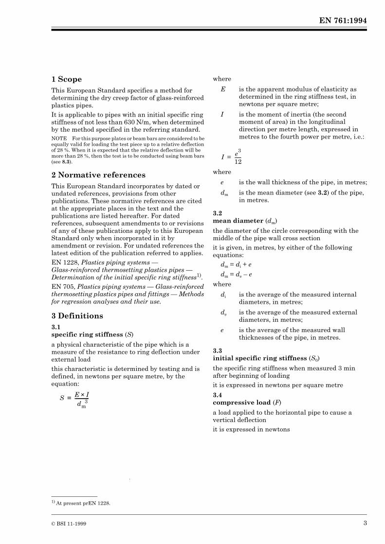
3 Definitions3.1 specific ring stiffness (S)
a physical characteristic of the pipe which is a measure of the resistance to ring deflection under external loadthis characteristic is determined by testing and is defined, in newtons per square metre, by the equation:
where
where
3.2 mean diameter (dm)
the diameter of the circle corresponding with the middle of the pipe wall cross sectionit is given, in metres, by either of the following equations:
dm = di + e
dm = de – e
where
3.3 initial specific ring stiffness (S0)
the specific ring stiffness when measured 3 min after beginning of loadingit is expressed in newtons per square metre
3.4 compressive load (F)
a load applied to the horizontal pipe to cause a vertical deflection it is expressed in newtons
1) At present prEN 1228.
S E I××dm
3-------------=
E is the apparent modulus of elasticity as determined in the ring stiffness test, in newtons per square metre;
I is the moment of inertia (the second moment of area) in the longitudinal direction per metre length, expressed in metres to the fourth power per metre, i.e.:
e is the wall thickness of the pipe, in metres;
dm is the mean diameter (see 3.2) of the pipe, in metres.
di is the average of the measured internal diameters, in metres;
de is the average of the measured external diameters, in metres;
e is the average of the measured wall thicknesses of the pipe, in metres.
the vertical change in diameter of a pipe in a horizontal position in response to a vertical compressive load (see 3.4)it is expressed in metres
3.6 initial deflection (y3 min)
the vertical deflection caused by the compressive load and measured 3 min (i.e. 0,05 h) after the beginning of loadingit is expressed in metres
3.7 long-term vertical deflection under dry conditions (yx, dry)
the estimated vertical deflection after x years, obtained by extrapolation of long-term deflection measurements at a constant load under dry conditionsit is expressed in metres
3.8 dry conditions
the test environment in air at the prevailing humidity
3.9 dry creep factor (!x, dry)
the factor given by the following equation:
where
3.10 deflection coefficient (f)
the coefficient which takes into account the second order theory and of which the value is given by the following equation:
f = {1860 + (2500 × y/dm)} × 10–5
4 PrincipleA cut length of pipe is subjected to a constant load along its length to compress it diametrically for a period of not less than 1 000 h. Its deflection is measured at intervals. The deflection after a specified time of x years is estimated by extrapolation.
The creep factor under dry conditions is determined from the relationship between the initial deflection and the deflection after x years of the same test piece (see 3.7 and 3.8).NOTE 1 If it is required to predict the deflection at 50 years this requires extrapolating approximately 2,5 decades (2,5 increments of lg t, where t is time in hours). In order to improve the reliability of the prediction the creep test may be extended beyond 1 000 h.NOTE 2 It is assumed that the following test parameters are set by the standard making reference to this standard:
a) the time to which the values are to be extrapolated (see 3.6, 3.7, 3.9 and clause 9);b) the length of each test piece (see 6.1);c) the number of test pieces (see 6.2);d) if applicable, the conditioning atmosphere and period (see clause 7);e) the test temperature and relative humidity (see 8.1);f) the periods of test pieces under load (see 8.4).
5 Apparatus5.1 Compressive loading machine, comprising a system by means of which one or more test pieces can be compressed by compressive load determined to an accuracy of 1 % of the maximum indicated applied value via two parallel load application surfaces conforming to 5.2.NOTE Care may be necessary to ensure that the applied load is not affected by friction effects.
5.2 Load application surfaces
5.2.1 General. The surfaces shall be provided by a pair of plates conforming to 5.2.2, or a pair of beam bars conforming to 5.2.3, or a combination of one such plate and one such bar, with their major axes perpendicular to and centred on the direction of application of load F by the compressive loading machine, as shown in Figure 1. The surfaces to be in contact with the test piece shall be flat, smooth, clean and parallel.5.2.2 Plate. Each plate shall have a length at least equal to the length of the test piece (see 6.1), a width of at least 100 mm and a thickness such that no visible bending or deformation of the plate shall occur during the test.5.2.3 Beam bar. Each beam bar shall be rigid, have rounded edges and shall have a length at least equal to the length of the test piece (see 6.1). For pipes with a nominal size of not more than 300 the width of the bar shall be (20 ± 5) mm. For pipes with a nominal size greater than 300 the width of the bar shall be (50 ± 5) mm. Each bar shall be so constructed and supported that other surfaces of the beam bar structure shall not come into contact with the test piece during the test.
5.2.4 Dimensional measuring devices, capable of determining the necessary dimensions (length, diameters, wall thickness) to an accuracy of within ± 1 % and of determining the change in diameter of the test piece in the vertical direction during the test to an accuracy of within ± 1 % of the maximum value of the measured change.NOTE The maximum value of the change to be measured depends upon the relative deflection specified in the referring standard.
6 Test piece6.1 Preparation
The test piece shall be a complete ring cut from the pipe to be tested. The length of the test piece shall be as specified in the referring standard, with permissible deviations of ± 5 %.
The cut ends shall be smooth and perpendicular to the axis of the pipe.Straight lines shall be drawn on the inside or the outside along the length of the test piece and repeated at 60° intervals around its circumference, to serve as reference lines.
6.2 Number
The number of test pieces shall be as specified in the referring standard.
Measure the length of the test piece along each reference line to an accuracy of ± 0,5 %.Calculate the average length, L, of the test piece, in metres.Reject or correct the test piece if it does not conform to 6.1.
6.3.2 Wall thickness
Measure to within ± 1 % the wall thickness of the test piece at each end of each reference line.Calculate the mean wall thickness, e, as the average of the measured values.
6.3.3 Mean diameter
Measure to an accuracy of within ± 1,0 % either of the following:
a) the internal diameter, di, of the test piece between each diametrically opposed pair of reference lines at their mid-lengths, e.g. by means of a calliper;b) the external diameter, de, of the test piece which includes the mid-points of the reference lines, e.g. by means of a circumferential wrap steel tape.
Determine the mean diameter, dm, of the test piece by calculation using the averaged values obtained for wall thickness and for either the average internal or the average external diameter at the mid-point of the six reference lines (see 6.1).
7 ConditioningStore the test pieces at the test temperature and relative humidity specified in the referring standard prior to testing.NOTE The age and storage conditions (temperature and relative humidity) of the test pieces can affect the results of the creep test.
8 Procedure8.1 Test temperature and relative humidity
Conduct the tests at the temperature and relative humidity specified in the referring standard.
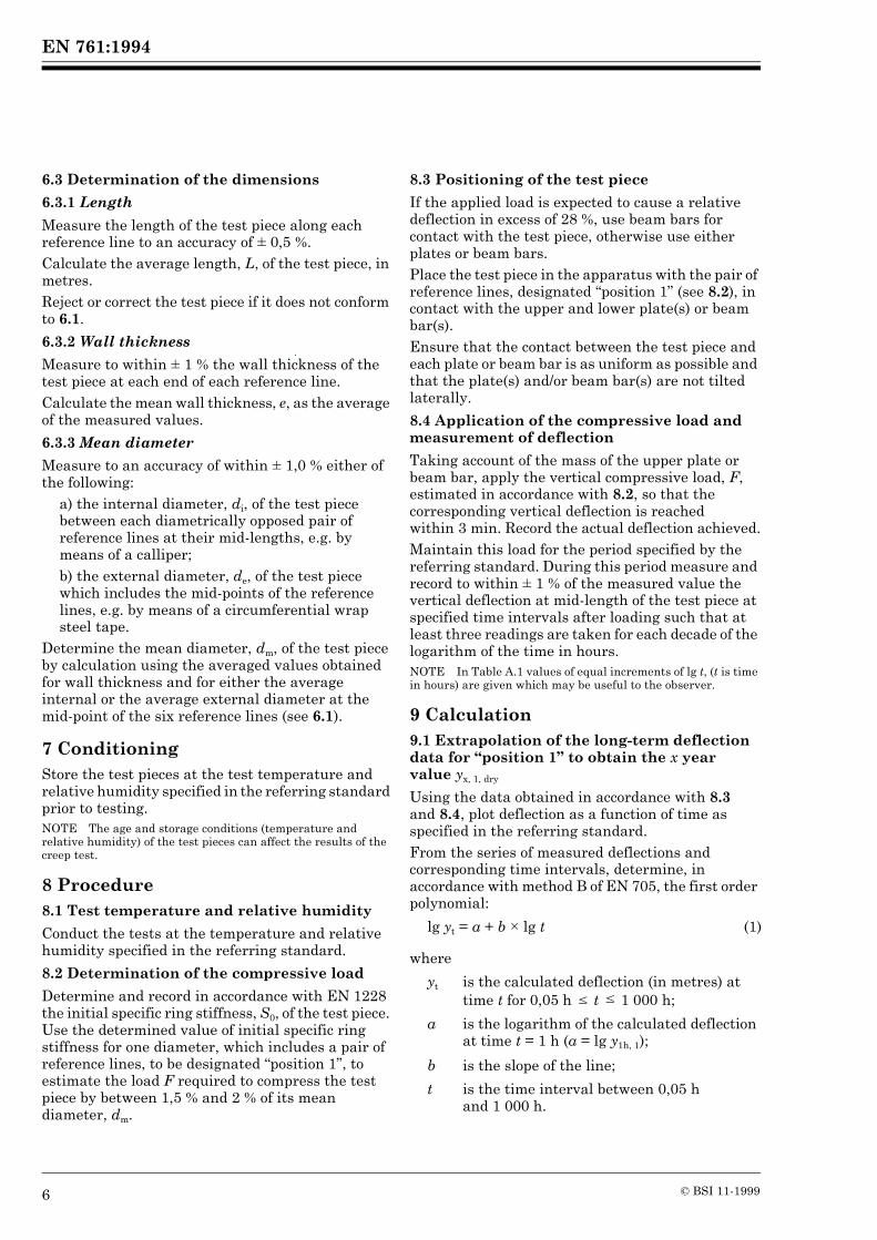
8.2 Determination of the compressive load
Determine and record in accordance with EN 1228 the initial specific ring stiffness, S0, of the test piece. Use the determined value of initial specific ring stiffness for one diameter, which includes a pair of reference lines, to be designated “position 1”, to estimate the load F required to compress the test piece by between 1,5 % and 2 % of its mean diameter, dm.
8.3 Positioning of the test piece
If the applied load is expected to cause a relative deflection in excess of 28 %, use beam bars for contact with the test piece, otherwise use either plates or beam bars.Place the test piece in the apparatus with the pair of reference lines, designated “position 1” (see 8.2), in contact with the upper and lower plate(s) or beam bar(s).Ensure that the contact between the test piece and each plate or beam bar is as uniform as possible and that the plate(s) and/or beam bar(s) are not tilted laterally.
8.4 Application of the compressive load and measurement of deflection
Taking account of the mass of the upper plate or beam bar, apply the vertical compressive load, F, estimated in accordance with 8.2, so that the corresponding vertical deflection is reached within 3 min. Record the actual deflection achieved.Maintain this load for the period specified by the referring standard. During this period measure and record to within ± 1 % of the measured value the vertical deflection at mid-length of the test piece at specified time intervals after loading such that at least three readings are taken for each decade of the logarithm of the time in hours.NOTE In Table A.1 values of equal increments of lg t, (t is time in hours) are given which may be useful to the observer.
9 Calculation9.1 Extrapolation of the long-term deflection data for “position 1” to obtain the x year value yx, 1, dry
Using the data obtained in accordance with 8.3 and 8.4, plot deflection as a function of time as specified in the referring standard.From the series of measured deflections and corresponding time intervals, determine, in accordance with method B of EN 705, the first order polynomial:
where
lg yt = a + b × lg t (1)
yt is the calculated deflection (in metres) at time t for 0,05 h k t k 1 000 h;
a is the logarithm of the calculated deflection at time t = 1 h (a = lg y1h, 1);
b is the slope of the line;
t is the time interval between 0,05 h and 1 000 h.
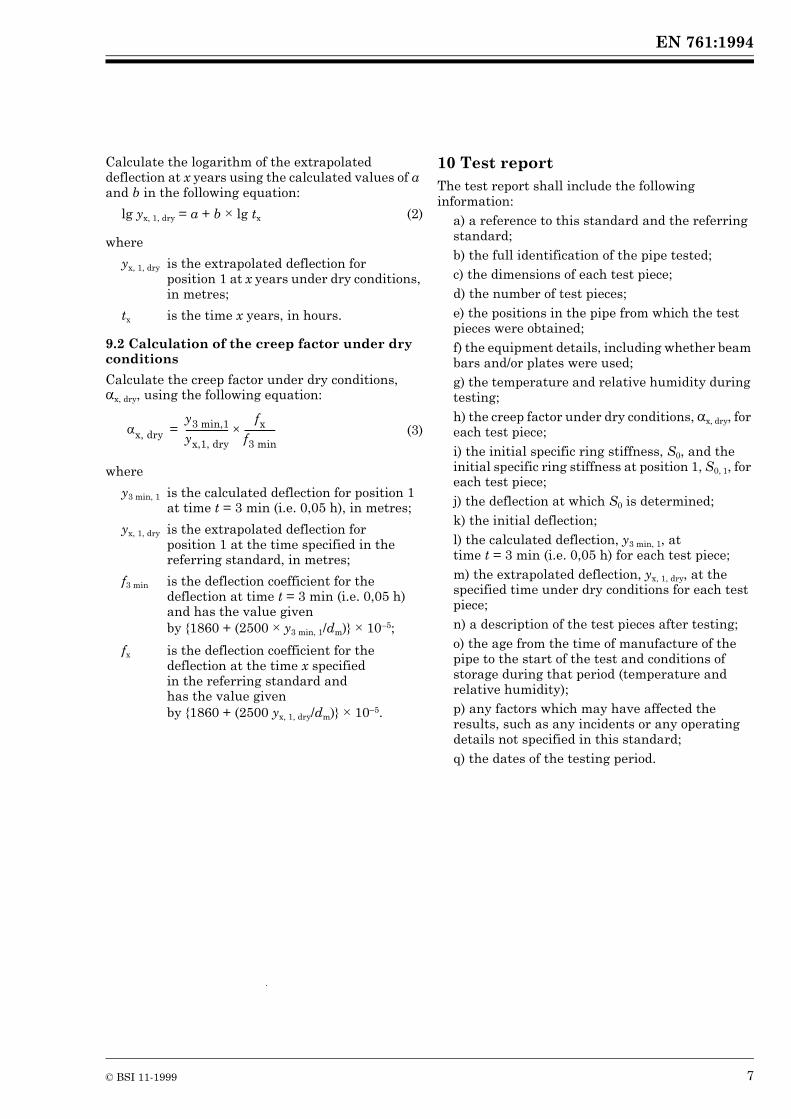
Calculate the logarithm of the extrapolated deflection at x years using the calculated values of a and b in the following equation:
where
9.2 Calculation of the creep factor under dry conditions
Calculate the creep factor under dry conditions, !x, dry, using the following equation:
where
10 Test reportThe test report shall include the following information:
a) a reference to this standard and the referring standard;b) the full identification of the pipe tested;c) the dimensions of each test piece;d) the number of test pieces;e) the positions in the pipe from which the test pieces were obtained;f) the equipment details, including whether beam bars and/or plates were used;g) the temperature and relative humidity during testing;h) the creep factor under dry conditions, !x, dry, for each test piece;i) the initial specific ring stiffness, S0, and the initial specific ring stiffness at position 1, S0, 1, for each test piece;j) the deflection at which S0 is determined;k) the initial deflection;l) the calculated deflection, y3 min, 1, at time t = 3 min (i.e. 0,05 h) for each test piece;m) the extrapolated deflection, yx, 1, dry, at the specified time under dry conditions for each test piece;n) a description of the test pieces after testing;o) the age from the time of manufacture of the pipe to the start of the test and conditions of storage during that period (temperature and relative humidity);p) any factors which may have affected the results, such as any incidents or any operating details not specified in this standard;q) the dates of the testing period.
lg yx, 1, dry = a + b × lg tx (2)
yx, 1, dry is the extrapolated deflection for position 1 at x years under dry conditions, in metres;
tx is the time x years, in hours.
(3)
y3 min, 1 is the calculated deflection for position 1 at time t = 3 min (i.e. 0,05 h), in metres;
yx, 1, dry is the extrapolated deflection for position 1 at the time specified in the referring standard, in metres;
f3 min is the deflection coefficient for the deflection at time t = 3 min (i.e. 0,05 h) and has the value given by {1860 + (2500 × y3 min, 1/dm)} × 10–5;
fx is the deflection coefficient for the deflection at the time x specified in the referring standard and has the value given by {1860 + (2500 yx, 1, dry/dm)} × 10–5.
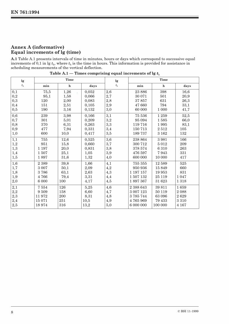
Annex A (informative)Equal increments of lg (time)A.1 Table A.1 presents intervals of time in minutes, hours or days which correspond to successive equal increments of 0,1 in lg th, where th is the time in hours. This information is provided for assistance in scheduling measurements of the vertical deflection.
Table A.1 — Times comprising equal increments of lg th
BSI — British Standards InstitutionBSI is the independent national body responsible for preparing British Standards. It presents the UK view on standards in Europe and at the international level. It is incorporated by Royal Charter.
Revisions
British Standards are updated by amendment or revision. Users of British Standards should make sure that they possess the latest amendments or editions.
It is the constant aim of BSI to improve the quality of our products and services. We would be grateful if anyone finding an inaccuracy or ambiguity while using this British Standard would inform the Secretary of the technical committee responsible, the identity of which can be found on the inside front cover. Tel: 020 8996 9000. Fax: 020 8996 7400.
BSI offers members an individual updating service called PLUS which ensures that subscribers automatically receive the latest editions of standards.
Buying standards
Orders for all BSI, international and foreign standards publications should be addressed to Customer Services. Tel: 020 8996 9001. Fax: 020 8996 7001.
In response to orders for international standards, it is BSI policy to supply the BSI implementation of those that have been published as British Standards, unless otherwise requested.
Information on standards
BSI provides a wide range of information on national, European and international standards through its Library and its Technical Help to Exporters Service. Various BSI electronic information services are also available which give details on all its products and services. Contact the Information Centre. Tel: 020 8996 7111. Fax: 020 8996 7048.
Subscribing members of BSI are kept up to date with standards developments and receive substantial discounts on the purchase price of standards. For details of these and other benefits contact Membership Administration. Tel: 020 8996 7002. Fax: 020 8996 7001.
Copyright
Copyright subsists in all BSI publications. BSI also holds the copyright, in the UK, of the publications of the international standardization bodies. Except as permitted under the Copyright, Designs and Patents Act 1988 no extract may be reproduced, stored in a retrieval system or transmitted in any form or by any means – electronic, photocopying, recording or otherwise – without prior written permission from BSI.
This does not preclude the free use, in the course of implementing the standard, of necessary details such as symbols, and size, type or grade designations. If these details are to be used for any other purpose than implementation then the prior written permission of BSI must be obtained.
If permission is granted, the terms may include royalty payments or a licensing agreement. Details and advice can be obtained from the Copyright Manager. Tel: 020 8996 7070.