39
Brittle Deformation
| Date post: | 17-Dec-2015 |
| Category: |
Documents |
| Upload: | tracy-moore |
| View: | 228 times |
| Download: | 1 times |

Brittle Deformation
Fracture A planar or curviplanar discontinuity
Forms as a result of brittle rock failure Under relatively low pressure and temperature
conditions in the earth crust
Rock fractures range in size from: Microcracks – Intragranular to intergranular
(fraction of a mm) Faults - Extend for hundreds of kilometers
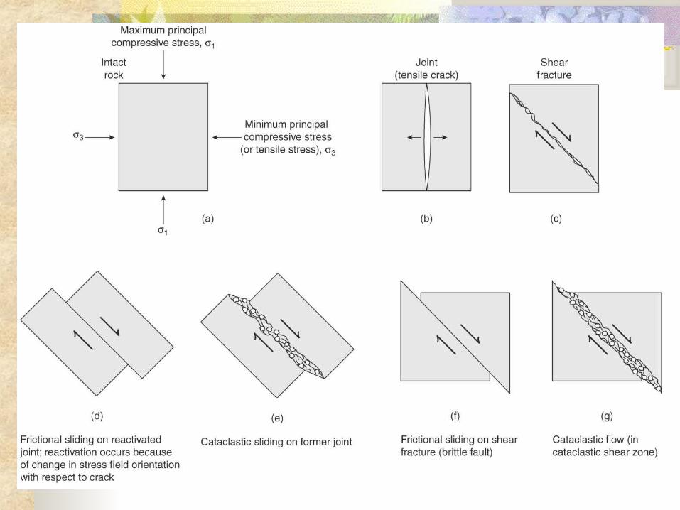
Brittle Deformation Permanent change in rocks by fracture or sliding on fractures
Fracture: A discontinuity across which cohesion (Co) is lost
The term fracture includes three basic types of discontinuities: Extension fracture (type I)
Relative movement normal to fracture surface Shear fracture (type II & III)
Relative movement parallel to fracture surface Oblique extension (hybrid) fracture
Relative movement is oblique to the fracture surface
Vein: fracture filled by secondary minerals
Four categories of fracture observation
1. Distribution and geometry of fracture system
2. Surface features of fracture
3. Relative timing of fracture formation
4. Geometric relation of fracture to other structures
Fracture set and system Fracture set: a group of fractures with
similar orientation and arrangement Small extension fractures are referred to as
joint Systematic joints: have roughly planar
surfaces, parallel orientation and regular spacing (vs. non-systematic joints)
Fracture system: two or more sets of fracture affecting the same volume of rock
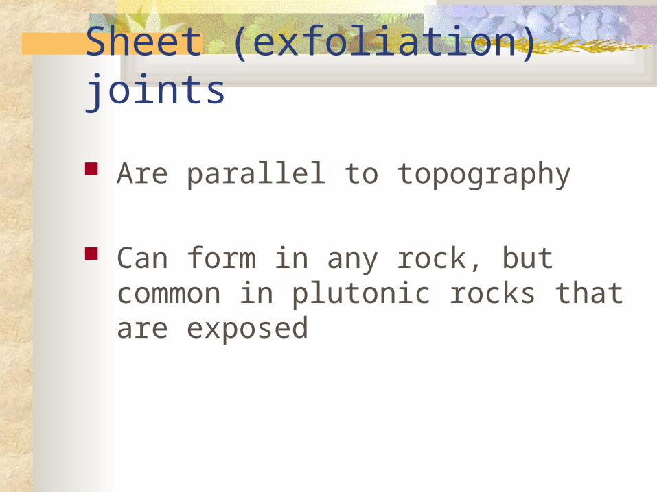
Sheet (exfoliation) joints
Are parallel to topography
Can form in any rock, but common in plutonic rocks that are exposed
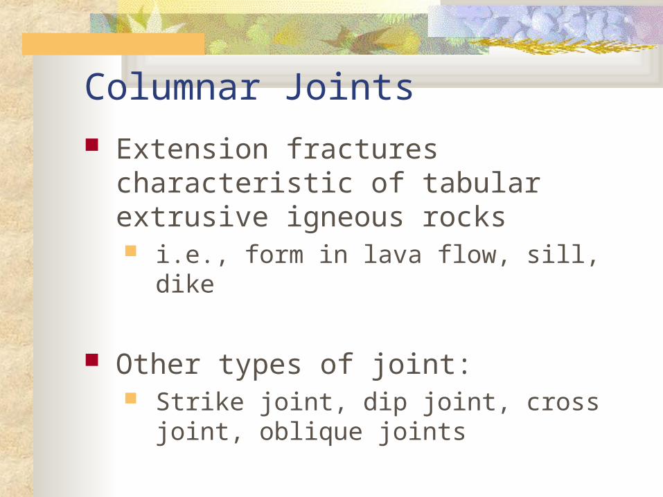
Columnar Joints
Extension fractures characteristic of tabular extrusive igneous rocks i.e., form in lava flow, sill, dike
Other types of joint: Strike joint, dip joint, cross joint, oblique
joints
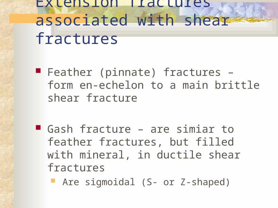
Extension fractures associated with shear fractures
Feather (pinnate) fractures – form en-echelon to a main brittle shear fracture
Gash fracture – are simiar to feather fractures, but filled with mineral, in ductile shear fractures Are sigmoidal (S- or Z-shaped)
What do we collect about fractures? Orientation (rose diagram, stereonet) Spacing Length Spatial pattern Relation to lithology Relation to layer (bed) thickness
Joints Are a type of fracture which form due to tension
They form parallel to the minimum tensile stress Perpendicular to maximum tensile stress Shearing is zero along joints when they form Also called cracks or tensile fractures
Joints form under: shallow depth, low confining pressure (Pc) elastic regime low temperature (T) high pore fluid pressures (Pf)
Joints Joints form perpendicular to the maximum
principal tensile stress i.e, along a principal plane of stress
Therefore joints dominantly show separation or opening of the walls of the fractures with no appreciable shear displacement parallel to the plane of the fracture Joints form through the Mode I crack surface
displacement Joints are commonly characterized by two
matching, rough, discontinuous, and curved surfaces, although they are approximated to be smooth, continuous, and planar
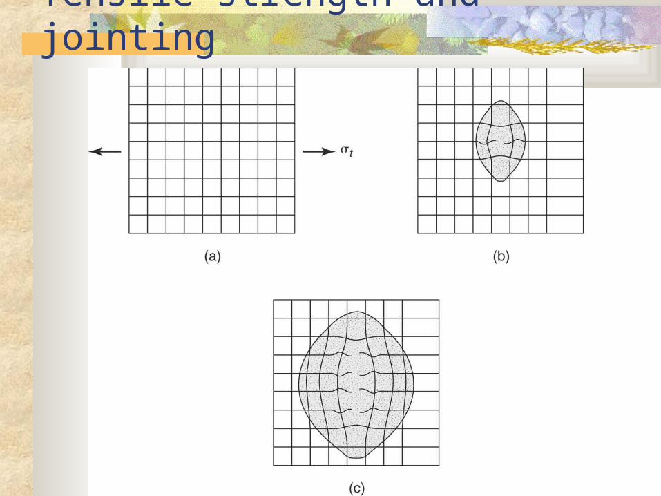
Tensile strength and jointing
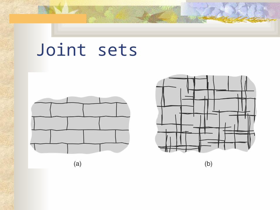
Joint sets
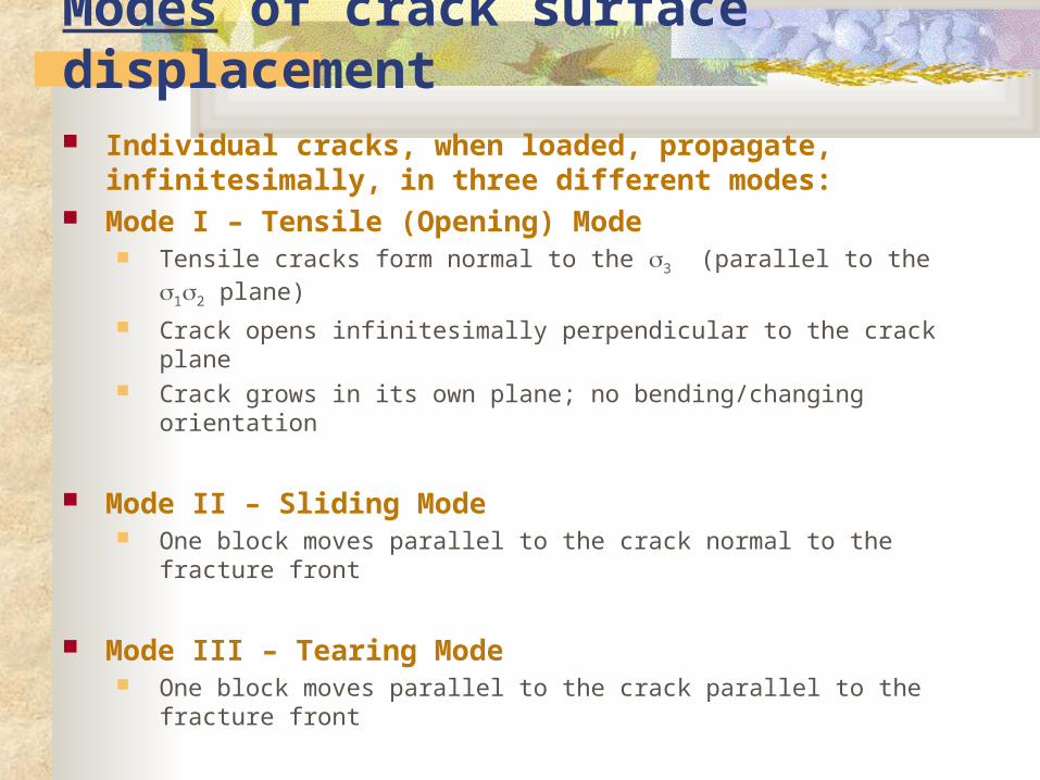
Modes of crack surface displacement Individual cracks, when loaded, propagate, infinitesimally,
in three different modes: Mode I – Tensile (Opening) Mode
Tensile cracks form normal to the 3 (parallel to the 12 plane)
Crack opens infinitesimally perpendicular to the crack plane Crack grows in its own plane; no bending/changing orientation
Mode II – Sliding Mode One block moves parallel to the crack normal to the fracture front
Mode III – Tearing Mode One block moves parallel to the crack parallel to the fracture front
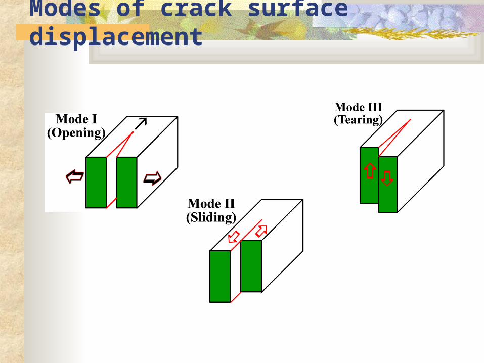
Modes of crack surface displacement
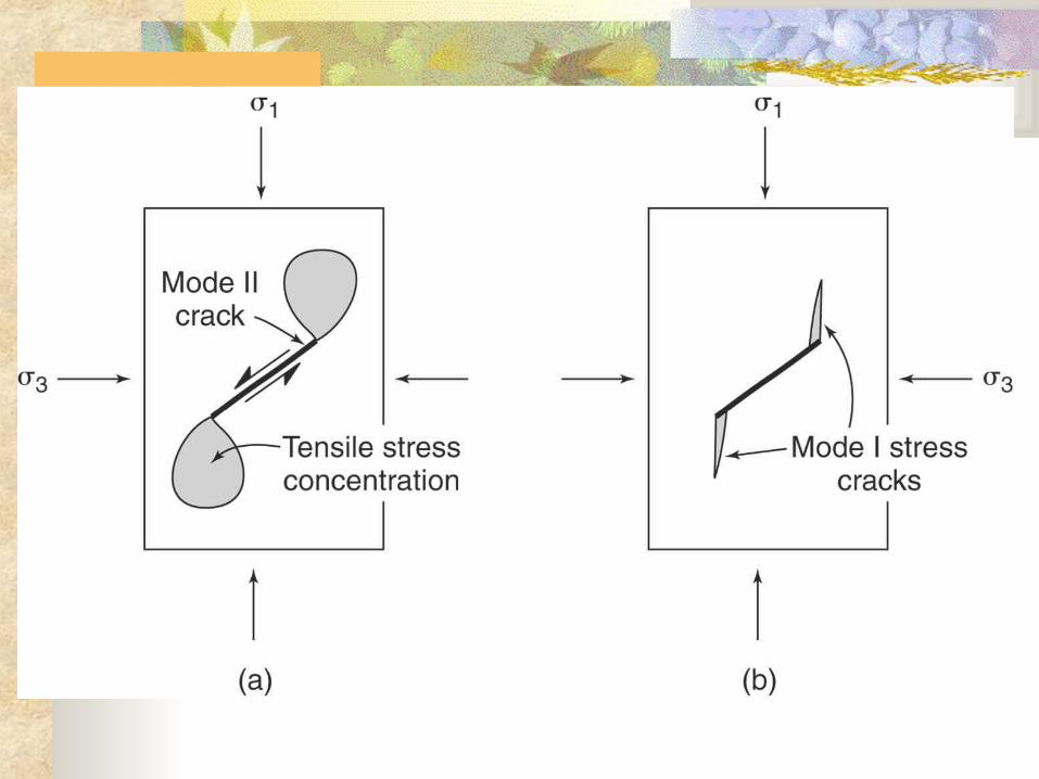
Modes of fracture
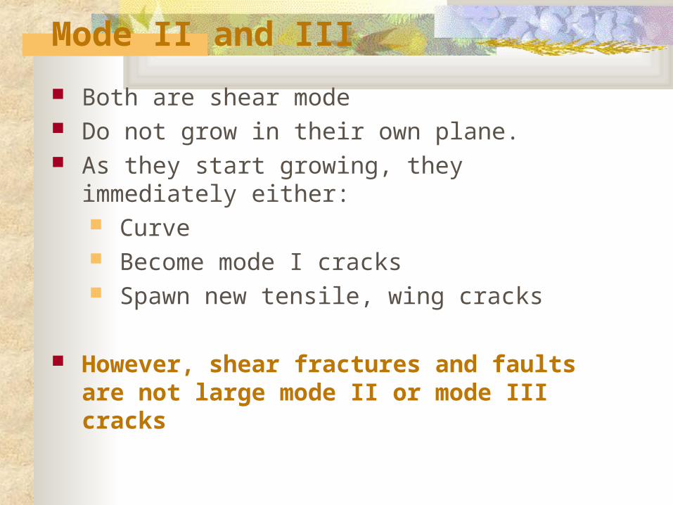
Mode II and III
Both are shear mode Do not grow in their own plane. As they start growing, they immediately either:
Curve Become mode I cracks Spawn new tensile, wing cracks
However, shear fractures and faults are not large mode II or mode III cracks
Joints The planar approximation is justified given that scale of
geometric irregularities (e.g. joint surface morphologies, curvature amplitude) is commonly very small compared to the size of the fracture surface
Termination of the two opposing surfaces at their distal edge or periphery (fracture front), i.e., a finite extent of the two walls Displacement is zero at the fracture fronts
Involve small relative displacement of the originally contiguous points compared to the in-plane dimensions of the fracture walls
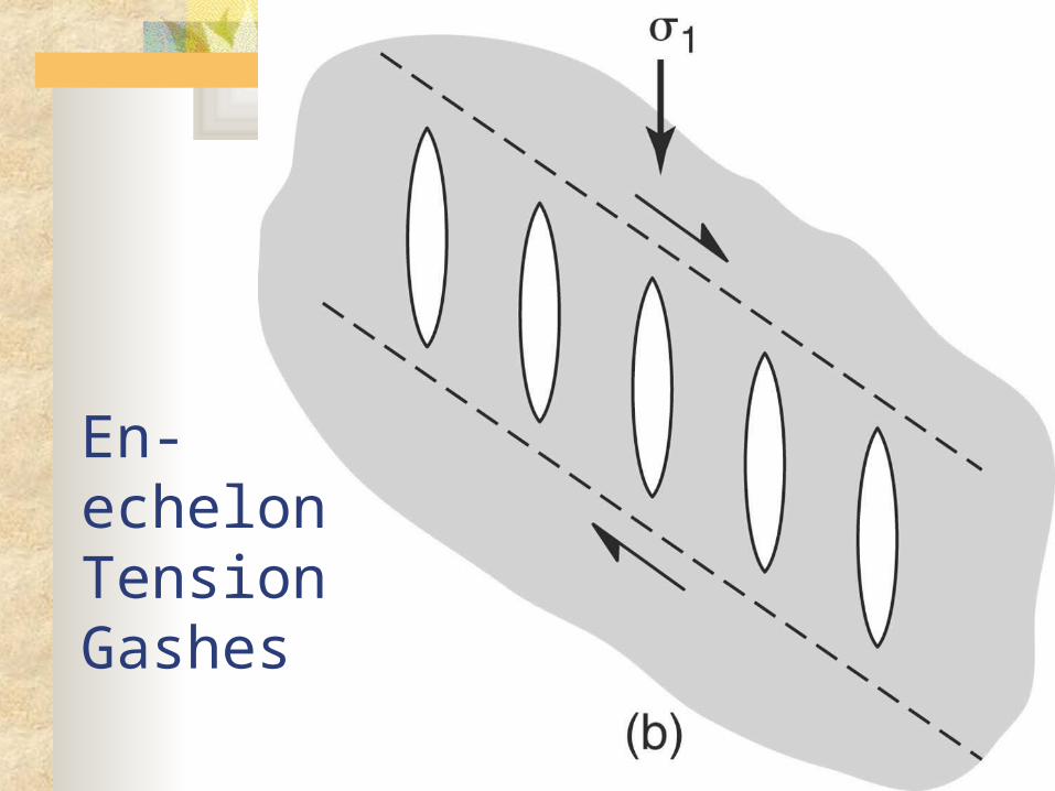
En-echelon Tension Gashes
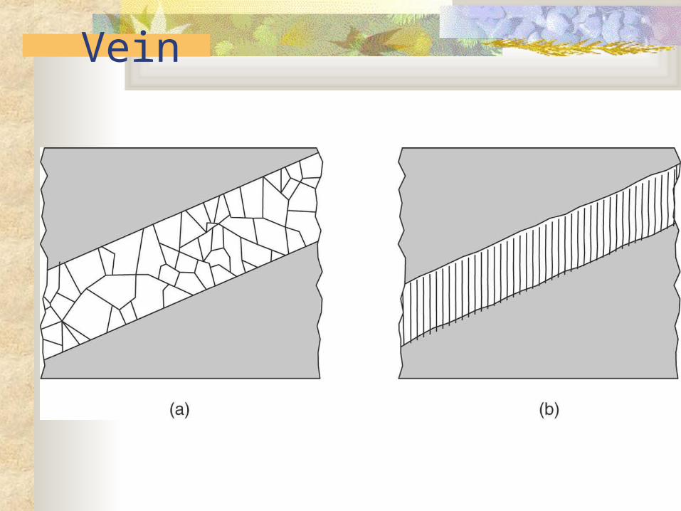
Vein
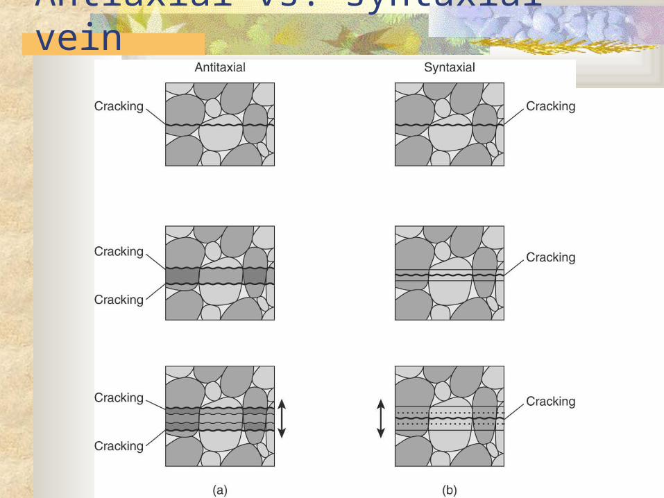
Antiaxial vs. syntaxial vein
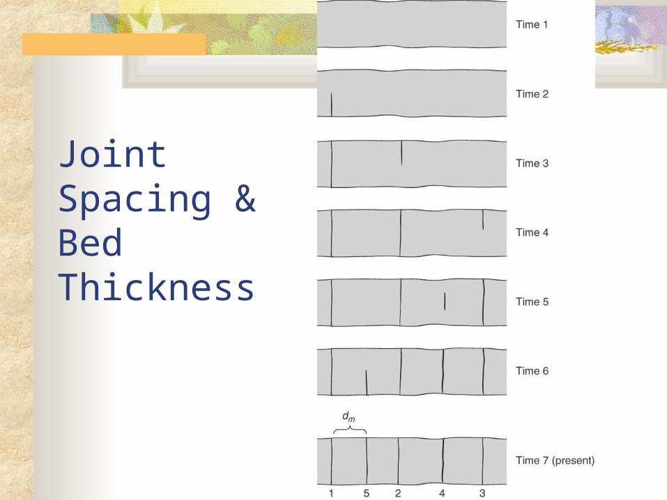
Joint Spacing &Bed Thickness
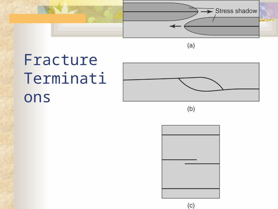
Fracture Terminations
Shear Fractures
Fractures along which there has been shearing or displacement
Shear fractures are small, with small displacement
They occur in intact rock during brittle deformation
If the amount of displacement is significant and measurable, the shear fracture is called fault
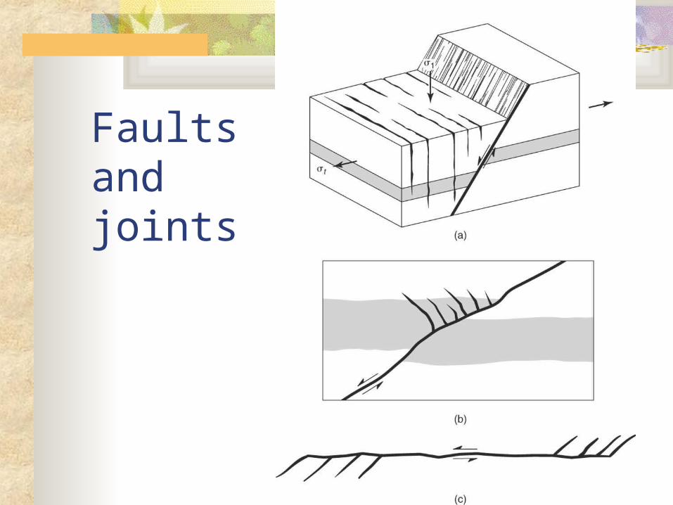
Faults and joints
Shear Fractures
Shear fractures, form at an angle to the maximum compressive stress and show offset because of the shear traction along the fractures
The hybrid shear fractures are discontinuities with a mixed mode of opening and shear and form oblique to the plane of the fracture as a result of both tensile normal stress and shear stress
Terminology
Fracture front: The line separating the fractured region from the un-fractured part of the rock
Fracture trace: Intersection of the fracture with any surface
Fracture tip: The termination of the fracture along the trace of the fracture
Joint Surface Morphology
Surface morphology of joints show evidence for initiation, propagation, and arrest
Theoretically, mode I loading in an isotropic, homogeneous material should lead to a smooth propagation with a mirror smooth surface
Joints however are not smooth, because rocks are commonly neither homogeneous nor isotropic
Out-of-plane Propagation
The orientation of the maximum tensile stress in front of a single crack tip may not be parallel to the normal to the parent crack
Cracks propagate so that “new’ portions of the crack remain normal to the local maximum tensile stress
This requires a crack to leave the plane of the parent crack in order to maintain its orientation relative to the local stress field
This out-of-plane propagation is so common in microscopic scale that leads to the formation of rough, non-smooth fractures surfaces
Crack Propagation Paths
Out of plane propagation is characterized by a combination of two end member crack propagation paths:
Twist: leads to segmentation of the crack into several smaller crack planes. Represents a rotation of the local maximum tensile stress
in the initial yz plane. Rotation is about an axis in the crack plane || to
propagation direction
Tilt: Causes the crack tip to rotate without segmentation. Rotation is about an axis in the crack plane _|_
propagation direction
Mesoscopic Joint Surface Although microscopic out-of-plane propagation is
common, joints appear smooth on the mesoscopic scale.
This is due to the homogeneous nature of the remote stress field
Even when the crack leaves its plane, the general propagation path remains normal to the remote maximum tensile stress
The microscopic out-of-plane propagation leads to the development of joint surface morphology
Plumose Surface Morphology Helps to interpret rupture nucleation, propagation, and
arrest Develops largely due to local twists and tilts during
propagation of a fracture which would otherwise be planar. Barbs: surface irregularities
In homogeneous rocks, barbs trace to the point of origin (an original crack)
In inhomogeneous rocks (sandstone, shale), barbs radiate from either a bedding plane or an inclusion in the bed (e.g., fossil, concretion, clast)
The point of origin may vary from bed to bed in shale or siltstone

Joint Initiation and Beds If joints initiate from bedding plane, they
often originate from irregularities such as ripples or sole marks
Joints in a bed often initiate from a common feature such as the upper bedding plane
Fossils and concretions often originate joints
in adjacent beds
Rupture Propagation The progress of rupture from the origin to the final arrest
leads to the formation of some patterns that are printed on the surface of joints
Mirror zone: Area immediately adjacent to the point of origin. Forms under small tip stress values, not big enough to
beak the material at oblique angles
Mist zone: Forms when larger stresses break bonds at oblique
angles to crack plane. On the fine scale, this oblique cracking forms a non-
smooth (misty) zone, separating the mirror from the hackle zone
Hackle zone
Forms when there are local components of twist during crack propagation.
Form when propagation occurs at a critical velocity when cracks branch or bifurcate
Hypothesis I: High velocities shift the maximum local tension away from the existing crack plane
Hypothesis II: High velocities form secondary cracks. The main crack then branches to follow the secondary cracks
Plumose Structures Also called feathers, hackle plumes, striations, or barbs.
These record rupture motion
Consists of an axis from which barbs mark the direction of the rupture front as portions diverge away from the plume axis
Barbs become more pronounced toward the edge of the beds away from the axis Barbs represent long, narrow planes oblique to the main
fracture plane. Barbs form similar to hackle marks due to twist
Plumose Structures …
Plumose structures have different shapes: Axes can be straight to curved Barbs vary from uniform to symmetrical
to asymmetrical about the axis
These variations reflect the degree to which rupture velocity was uniform during propagation
Arrest of Rupture Arrest lines show up as ridges or cusped waves
normal or subnormal to the direction of propagation of cracks
At arrest lines a large component of tilt is involved in the out-of-plane crack propagation
Arrest lines may be the boundaries between areas with perceptible barbs and areas with no barbs.
Rock joints may show several arrest lines in a row or a single arrest line at the end of a long fracture
Several arrest lines represent intermediate slowing or stopping points for a rupture as it moves through the rock to form a joint


