BROADBAND IRREGULAR RHOMBUS SLOTTED MICROSTRIP ANTENNA FOR WLAN APPLICATION
Jeetendra rai1 , Dr.S.R Nigam2, Dr.D.C.Dhubkariya3 Research scholar Aisect University Bhopal,
Prof. Aisect University Bhopal, Prof. BIET jhansi
Abstract— The design of a irregular rhombus slotted microstrip antenna with linear polarization. the antenna have a extended bandwidth of 82.35% which is very high and the efficiencies are more than 80% to 95%, and the gain is near about to 4 dBi. The antenna is used for the WLAN ,the proposed antenna is able to used for several application because of the impedance bandwidth is very high , its lies between 1.2GHz to 2.9 GHz.
1. INTRODUCTION- Antennas are a very important component of communication systems. by definition, an antenna is a device used to transform an RF signal, traveling on a conductor, in to an electromagnetic wave in free space the broadband circularly polarized microstrip antennas play a vital role in wireless communication due to its low-profile, small-size and light weight. As well know, a linearly polarized wave can be obtained when spatially orthogonal modes are excited with equal amplitude. The input impedance of the antenna must identically match the characteristic impedance of the transmission line in order to achieve maximum energy transfer between a transmission line and an antenna. If the input impedance of the antenna does not match with the characteristic impedance of the transmission line, a reflected wave will be generated at the antenna terminal and travel back towards the energy source. This reflection of energy results in a reduction in the overall system efficiency. Conventional designs of microstrip antennas for linear polarization are usually achieved by [3] cutting rectangular slots in the rectangular patch .
2 . SUBSTRATE MATERIAL SELECTION- The first design step is to chose a suitable dielectric substrate of appropriate thickness h =1.6 mm and loss tangent =.0012 . A thick substrate is mechanical strong , will increases the radiated power , reduce conductor loss, and improved impedance
bandwidth however, it will also increase the weight, dielectric loss, surface wave loss , and radiations from the probe field .
3. ANTENNA DESIGN-
Fig. 1 shows the geometry of the proposed broadband
microstrip antenna, The radiating irregular rhombus patch,
designed on a substrate of thickness h and relative
permittivity Ɛr , has the dielectric material thickness is 1.6mm
the length of radiating patch, Lp = 44.4 mm and Wp = 57 mm
is excited by the coaxial feed probe, which are oriented in
orthogonal directions and have the distance of feed point
is X= 49 mm. and Y=33.3mm .
Fig. 1: Geometry of Proposed antenna on IE3D
3. SIMULATED RESULTS –
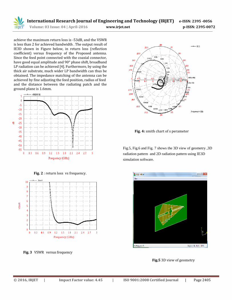
The antenna has been simulated with IE3D software Fig.2, Fig.3 and Fig. 4 shows the Reflection coefficient (S11) Vs frequency , VSWR versus frequency and smith chart of the proposed antenna .From the simulation results, we observe that the proposed antenna is able to
International Research Journal of Engineering and Technology (IRJET) e-ISSN: 2395 -0056
achieve the maximum return loss is -53dB, and the VSWR is less than 2 for achieved bandwidth . The output result of IE3D shown in Figure below, in return loss (reflection coefficient) versus frequency of the Proposed antenna. Since the feed point connected with the coaxial connector, have good equal amplitude and 90° phase shift, broadband LP radiation can be achieved [4]. Furthermore, by using the thick air substrate, much wider LP bandwidth can thus be obtained. The impedance matching of the antenna can be achieved by fine adjusting the feed position, radius of feed and the distance between the radiating patch and the ground plane is 1.6mm.
Fig. 2 : return loss vs frequency.
Fig. 3 VSWR versus frequency
Fig. 4: smith chart of s perameter
Fig.5, Fig.6 and Fig. 7 shows the 3D view of geometry ,3D
radiation pattern and 2D radiation pattern using IE3D
simulation software.
Fig.5 3D view of geometry
International Research Journal of Engineering and Technology (IRJET) e-ISSN: 2395 -0056
Fig. 11 Antenna and radiation efficiency vs Frequency
In this paper, a new design of broadband irregular rhombus slotted microstrip antenna at 1.6 GHz . The antenna have different outputs by using IE3D. A thick air substrate of 1.6 mm is used in the present proposed design, and impedance matching is obtained ,impedance bandwidth is 82.92 % through the irregular radiating patch. The results show that the proposed antenna is able for WLAN and some other applications.
4. CONCLUSIONS- Characteristics of a design of broadband LP irregular slotted microstrip antenna have been studies. The proposed antenna is achieved by using the different results show that the broadband LP microstrip antenna is able for WLAN and some other applications.
REFERENCES
[1] A. Balanis, “Antenna Theory analysis and design”, Microstrip Antenna, Chapter 14, pp.720-784 [2] Wang Yazhou, Su Donglin, Xiao Yongxuan, “Broadband circularly Polarized square microstrip antenna”, paper appear in ISAPE ,Guilin, 7th international symposium,published on 26-29 october 2006,pp.1-4. [3] K.Shambavi , “Gain and Bandwidth Enhancement Technique in Square Microstrip Antenna for WLAN application”, Asia-Pacific Microwave Conference 2007,pp.4284-4287. [4] Z. L. Dafalla, W. T. Y. Kuan, A. M. Abdel Rahman, and S. C. Shudakar, “Design of a Rectangular Microstrip Patch Antenna at 1 GHz”, Rf And Microwave Conference, October 5 - 6- 2004 ,Subang, Selangor, Malaysia. [5] C.Y. Chiu, C.H. Chan and K.M. Luke , “Study of slotted microstrip patch antennas with folded patch feed ”, Microwave Antennas propagation., vol. 152, no. 5, october 2005 [6] C-Y Huang, J-Y Wu and K-L Wong.Cross-slot-coupled microstrip antenna and dielectric resonator antenna for circular polarization. IEEE Trans on Antennas and Propagat, 1999,47. [7] S Matsuzawa and K Ito. Circularly polarized printed antenna fed by coplanar waveguide. Electron. Lett, Vol.32 No.22, 1996 [8] S. D. Targonski and D. M. Pozar. Design of wide-band circularly polarized aperture coupled microstrip antenna. IEEE Trans on Antennas and Propagat, vol. 41, pp. 214-220, 1993.