Page 1 of 27 Broadcast Engineering Consultants India Limited (Under Ministry Of Information and Broadcasting) C-56 A/17, Sector-62, Noida 22 nd July, 2016 CORRIGENDUM-I Reference:-RFP No.-BECIL/EMMC/CIVIL II/2016-17 Dated: 08th July 2016 Subject: Corrigendum for RFP invited for “Civil & Interior /Modular/ IT Networking & MEP (Mechanical Electrical and Plumbing) Works for Electronic Media Monitoring Centre set up at 11th Floor of Soochna Bhawan, New Delhi. Following clauses are amended in above mentioned RFP: 1. UNDER SECTION –III SPECIFICATION APPROVED MAKES OF HVAC FOR EQUIPMENT & MATERIALS S. No. EQUIPMENT AND MATERIAL ACCEPTABLE MAKE A. EQUIPMENT 1. Ductable Split Units Daikin/Mitsubishi/Scheinder 2. Non Ductable Split Units Daikin/Mitsubishi/Scheinder 3. Compressor for Split Units Daikin/Mitsubishi/Scheinder 4. Non Ductable Split Units for UPS Room Daikin/Mitsubishi/Scheinder 5. Voltage Stabilisers Logicstat 6. Motors ABB/Siemens/Bharat Bijli 7. V-Belts Fenner India/Dunlop 8. Inline Fans Sphere Vent/ Tristar 9. Propeller Fans Alstom Marathan or eq
Transcript
Page 1 of 27
Broadcast Engineering Consultants India Limited
(Under Ministry Of Information and Broadcasting)
C-56 A/17, Sector-62, Noida
22nd July, 2016
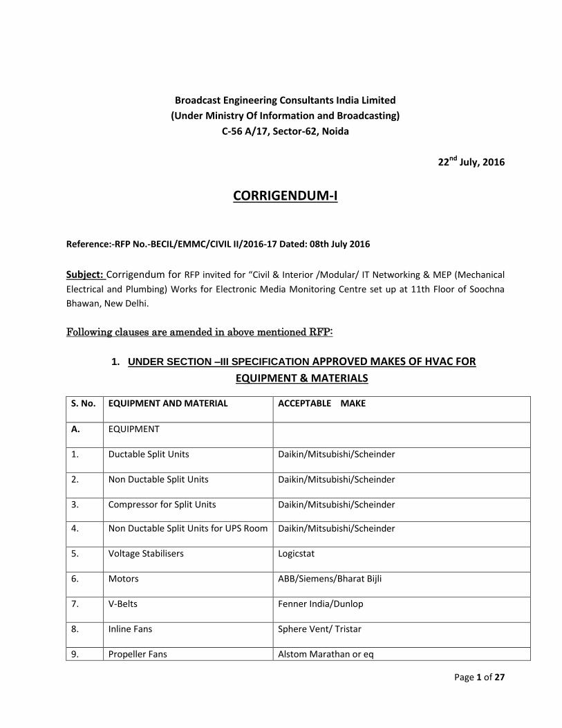
CORRIGENDUM-I
Reference:-RFP No.-BECIL/EMMC/CIVIL II/2016-17 Dated: 08th July 2016
Subject: Corrigendum for RFP invited for “Civil & Interior /Modular/ IT Networking & MEP (Mechanical
Electrical and Plumbing) Works for Electronic Media Monitoring Centre set up at 11th Floor of Soochna
Bhawan, New Delhi.
Following clauses are amended in above mentioned RFP:
1. UNDER SECTION –III SPECIFICATION APPROVED MAKES OF HVAC FOR
EQUIPMENT & MATERIALS
S. No. EQUIPMENT AND MATERIAL ACCEPTABLE MAKE
A. EQUIPMENT
1. Ductable Split Units
Daikin/Mitsubishi/Scheinder
2. Non Ductable Split Units
Daikin/Mitsubishi/Scheinder
3. Compressor for Split Units Daikin/Mitsubishi/Scheinder
4. Non Ductable Split Units for UPS Room
Daikin/Mitsubishi/Scheinder
5. Voltage Stabilisers Logicstat
6. Motors ABB/Siemens/Bharat Bijli
7. V-Belts Fenner India/Dunlop
8. Inline Fans
Sphere Vent/ Tristar
9. Propeller Fans Alstom Marathan or eq
Page 2 of 27
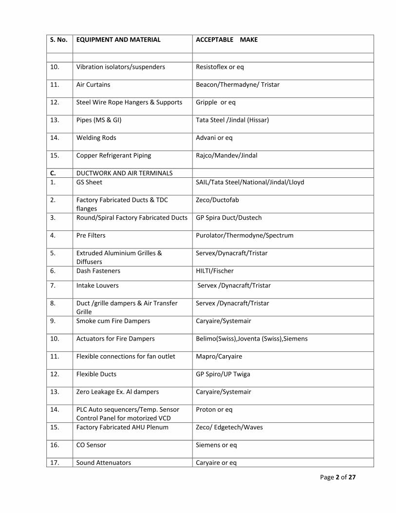
S. No. EQUIPMENT AND MATERIAL ACCEPTABLE MAKE
10. Vibration isolators/suspenders Resistoflex or eq
11. Air Curtains
Beacon/Thermadyne/ Tristar
12. Steel Wire Rope Hangers & Supports
Gripple or eq
13. Pipes (MS & GI) Tata Steel /Jindal (Hissar)
14. Welding Rods Advani or eq
15. Copper Refrigerant Piping Rajco/Mandev/Jindal
C. DUCTWORK AND AIR TERMINALS
1. GS Sheet SAIL/Tata Steel/National/Jindal/Lloyd
2. Factory Fabricated Ducts & TDC flanges
Zeco/Ductofab
3. Round/Spiral Factory Fabricated Ducts GP Spira Duct/Dustech
4. Pre Filters Purolator/Thermodyne/Spectrum
5. Extruded Aluminium Grilles & Diffusers
Servex/Dynacraft/Tristar
6. Dash Fasteners HILTI/Fischer
7. Intake Louvers Servex /Dynacraft/Tristar
8. Duct /grille dampers & Air Transfer Grille
Servex /Dynacraft/Tristar
9. Smoke cum Fire Dampers Caryaire/Systemair
10. Actuators for Fire Dampers Belimo(Swiss),Joventa (Swiss),Siemens
11. Flexible connections for fan outlet Mapro/Caryaire
12. Flexible Ducts GP Spiro/UP Twiga
13. Zero Leakage Ex. Al dampers
Caryaire/Systemair
14. PLC Auto sequencers/Temp. Sensor Control Panel for motorized VCD
Proton or eq
15. Factory Fabricated AHU Plenum Zeco/ Edgetech/Waves
16. CO Sensor Siemens or eq
17. Sound Attenuators Caryaire or eq
Page 3 of 27
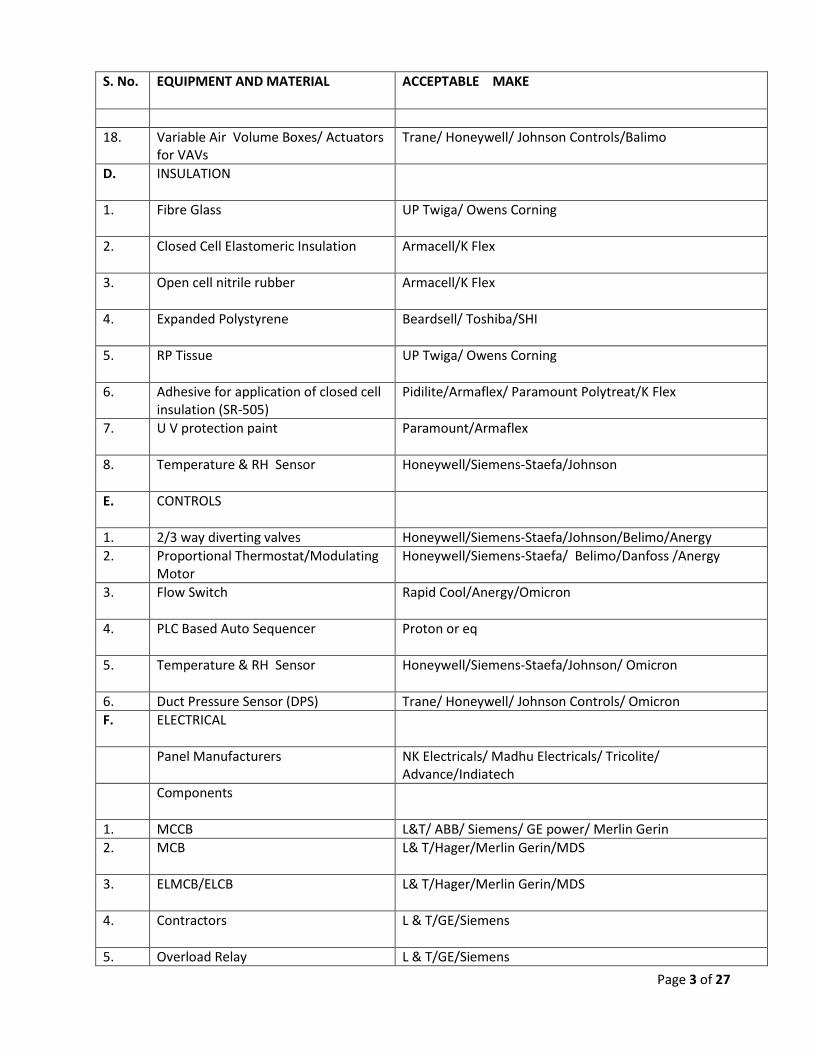
S. No. EQUIPMENT AND MATERIAL ACCEPTABLE MAKE
18.
Variable Air Volume Boxes/ Actuators for VAVs
Trane/ Honeywell/ Johnson Controls/Balimo
D. INSULATION
1. Fibre Glass
UP Twiga/ Owens Corning
2. Closed Cell Elastomeric Insulation
Armacell/K Flex
3. Open cell nitrile rubber
Armacell/K Flex
4. Expanded Polystyrene
Beardsell/ Toshiba/SHI
5. RP Tissue
UP Twiga/ Owens Corning
6. Adhesive for application of closed cell insulation (SR-505)
Pidilite/Armaflex/ Paramount Polytreat/K Flex
7. U V protection paint Paramount/Armaflex
8. Temperature & RH Sensor
Honeywell/Siemens-Staefa/Johnson
E. CONTROLS
1. 2/3 way diverting valves Honeywell/Siemens-Staefa/Johnson/Belimo/Anergy
2. Proportional Thermostat/Modulating Motor
Honeywell/Siemens-Staefa/ Belimo/Danfoss /Anergy
3. Flow Switch Rapid Cool/Anergy/Omicron
4. PLC Based Auto Sequencer Proton or eq
5. Temperature & RH Sensor
Honeywell/Siemens-Staefa/Johnson/ Omicron
6. Duct Pressure Sensor (DPS) Trane/ Honeywell/ Johnson Controls/ Omicron
F. ELECTRICAL
Panel Manufacturers NK Electricals/ Madhu Electricals/ Tricolite/ Advance/Indiatech
Components
1. MCCB L&T/ ABB/ Siemens/ GE power/ Merlin Gerin
2. MCB L& T/Hager/Merlin Gerin/MDS
3. ELMCB/ELCB L& T/Hager/Merlin Gerin/MDS
4. Contractors L & T/GE/Siemens
5. Overload Relay L & T/GE/Siemens
Page 4 of 27
S. No. EQUIPMENT AND MATERIAL ACCEPTABLE MAKE
Cables
1. Power Cables Gloster/Skytone/Gemscab/National/ Havells
2. Copper Control Cables Finolex/ National/Skyline/Rallison
3. Cable Gland Commet
4. Lugs Dowels
5. Connectors Elmec/ VKS/ ESSEN
Meters/Indicators
1. Ammeters/Volmeters (Digital Type)
L&T/Rishab/AE/Enercon/Secure
2. Indicating Lamps (LED Type)/Push Buttons
Siemens/ESBEE/L&T
3. Current Transformer AE/L&T/EE/AVK-SEGC
4. Selector Switches Salzer (l&T), Kaycee
NOTES :
1. Make of any other equipment/ material not mentioned above shall be got approved from
the Architects/ Owners before execution.
2. Relevant catalogue to be submitted along with the offers.
3. Relevant Test Certificates to be produced for various equipment & material during billing
process.
4. Under electrical, wherever, there is multiple choices of brands /approved makes, the
brands/make nominated by Owners/ Architects out of the multiple brands shall have to
be supplied.
Page 5 of 27
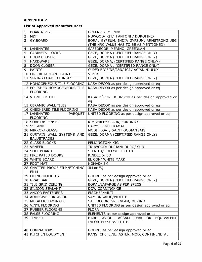
2. UNDER SECTION –III SPECIFICATION LIST OF APPROVED MANUFACTURES OF
CIVIL & INTERIOR , PLUMBING (Sanitary Fittings and Fixtures)
S.No. Material Conforming to Brand Names
1 Vitreous China Sanitaryware IS :2556 Part 11974 Kohler, American Standard, Roca
2 Plastic W.C. Seats IS: 2548 - 1967 Kohler, American Standard, Roca
5. UNDER SECTION –III SPECIFICATION Technical Specification of UPS (Schneider/Emerson, specs has to be matched)
PART 1 - GENERAL
1.1 SUMMARY A. Scope: Provide design and engineering, labor, material, equipment, related services, and
supervision required, including, but not limited to, manufacturing, fabrication, erection, and installation for a solid state uninterruptible power supply (UPS) as required for the complete performance of the work, and as shown on the Drawings and as herein specified.
B. Section includes: The work specified in this Section includes, but shall not be limited to, a three-phase, on-line, double conversion, solid state UPS. The UPS shall operate in conjunction with the existing building electrical system to provide high quality power conditioning, back-up power protection, and distribution for electronic equipment loads. The system shall consist of a solid state IGBT rectifier/inverter, power factor corrected rectifier, a 100 percent rated for continuous duty static switch, battery plant, graphical status/control panel, and synchronizing circuitry as described herein.
1.2 [Parallel] SYSTEM DESCRIPTION A. General characteristics
a. Up to five UPS units for redundancy b. Up to four UPS units for capacity
3. Front access only required for service 4. Top or bottom cable entry 5. High efficiency (96% at low load levels from 25% to 75%) 6. Battery charging in bypass operation
B. Design requirements: 1. Capacity: As per design 2. Parallel system: Parallel system shall be comprised of as per design redundancy. 3. Battery: Each UPS battery system shall be sized at power factor 0.9 for 15 minutes. 4. MBP cum I/O Cabinet: Separate wrap around Maintenance Bypass cum I/O cabinet for input &
output aluminum cable termination for quick/error free and easy installation as well as safe maintenance.
C. System characteristics: 1. Input: The system input shall be configurable for either single or dual utility derived from a
three phase wye source. The system should facilitate both top and bottom cable entry and suitable for aluminum cable termination. a. Input voltage: 415 volts AC three-phase, 3-wire (L1, L2, L3 + PE). b. Frequency: 40-70 Hertz c. Input power factor correction:
e. Generator ramp-in adaptable: 10-40 seconds f. Rated conditional short-circuit current Icc: 65 kA RMS at required breaker. g. Rated peak withstand current Ipk: Icc x 2.2 h. Protection: Built-in / External back-feed contactor for both, mains and bypass input. i. Fan redundancy: Redundant cooling fan in each section of the UPS at 100% rated load. j. Inrush Current: Less than nominal input current for less than one cycle. Shall not exceed
800% of the rectifier/battery charger full load current.
2. Bypass: a. Bypass voltage: 415 volts AC three-phase, 3-wire (L1, L2, L3 + PE) or 4-wire (L1, L2, L3 + N +
PE). b. Frequency: 50 or 60 Hz
3. UPS output:
a. Output voltage: 415 volts AC, ±1 percent steady state variation phase-to-phase voltage volts AC, three- phase, 3-wire (L1, L2, L3 + PE) or 4 wire.
b. Frequency: 50/60 hertz, ±1.0 percent (free running) c. Output voltage range
1) Symmetric load (0-100%): a) ± 1% static b) ± 5% after 2 ms c) ± 1% after 50 ms
d. Output Voltage Transient Response: The output voltage returns to within ±1% of the steady state value within 50ms.
e. Output power factor: 0.9 f. Output Voltage Transient Characteristics:
g. Total Harmonic Distortion (THDU): 1) < 2% at 100% linear load 2) < 3% at 100% non-linear load
h. Slew rate (Hz/sec): Programmable 0.25, 0.5, 1, 2, 4 ,6 i. Load power factor: 0.7 leading to 0.5 lagging without de-rating j. Overload rating:
1) Normal operation: a) 150% for 1 minute at 40 °C b) 125% for 10 minutes at 40 °C
2) Battery operation: a) 150% for 1 second b) 125% for 1 minute at 40 °C
3) Bypass operation: a) 1000% for 100 ms
Page 16 of 27
k. System AC-AC efficiency: 1) Greater than 96% in normal operation from 25% to 100% load 2) Greater than 98% in E-conversion operation from 25% to 100% load 3) Greater than 99% in ECO mode operation from 25% to 100% load
4. Battery:
a. Battery voltage: 480 volts DC nominal b. Charging power in % of output power:
c. Battery test: Manual or automatic (selectable) d. Deep discharge protection e. Recharge according to battery temperature f. Cold start without additional equipment g. Battery type: Valve regulated sealed lead acid (VRLA). Either in traditional top terminal
1.3 SUBMITTALS A. Product data: Submit product data showing material proposed. Submit sufficient information to
determine compliance with the Drawings and Specifications. Product data shall include, but shall not be limited to, the following: 1. Catalog sheets and technical data sheets to indicate physical data and electrical performance,
electrical characteristics, and connection requirements. 2. Manufacturer’s installation instructions indicating application conditions and limitations of use
stipulated by product inspecting and testing agency. Include instructions for storage, handling, protection, examination, preparation, installation, and starting of the product. Include equipment installation outline, connection diagram for external cabling, internal wiring diagram, and written instruction for installation.
B. Shop drawings: Submit shop drawings for each product and accessory required. Include information not fully detailed in manufacturer’s standard product data, including, but not limited to, complete electrical characteristics and connection requirements. Provide detailed equipment outlines with cabinet dimensions and spacing requirements; location of conduit entry/exit paths; location of floor/seismic mounting; available battery types/sizes; cabinet weights; heat rejection and air flow requirements; single line diagram; and control and external wiring.
C. Wiring diagrams: Submit wiring diagrams detailing power, signal, and control systems, clearly differentiating between manufacturer installed wiring and field installed wiring, and between components provided by the manufacturer and those provided by others.
D. Contract closeout submittals: 1. Project record documents: Submit a complete set of installation drawings showing all the
information specified elsewhere in this Section. 2. Operation and maintenance data: Submit operation and maintenance data to include in
operation and maintenance manuals specified in [Division 01 - GENERAL REQUIREMENTS]
Page 17 of 27
[Division 1 - GENERAL REQUIREMENTS], including, but not limited to, safe and correct operation of UPS functions.
1.4 QUALITY ASSURANCE A. Qualifications:
1. Manufacturer qualifications: Manufacturer shall be a firm engaged in the manufacture of solid state UPS of types and sizes required, and whose products have been in satisfactory use in similar service for a minimum of 20 years. a. The manufacturer shall be ISO 9001 certified and shall be designed to internationally
accepted standards. B. Regulatory requirements: Comply with applicable requirements of the laws, codes, ordinances, and
regulations of Federal, State, and local authorities having jurisdiction. Obtain necessary approvals from such authorities. 1. The UPS shall meet the requirements of the following standards:
a. Safety: 1) IEC 62040-1: 2008-06, 1st edition Uninterruptible Power Systems (UPS) - Part 1:
General and safety requirements for UPS 2) EN 62040-1: 2013-01, 1st edition amendment 1
b. EMC/EMI/RFI: 1) IEC 62040-2: 2005-10, 2nd edition Uninterruptible Power Systems (UPS) - Part 2:
Electromagnetic compatibility (EMC) requirements c. Performance:
1) IEC 62040-3: 2011-03, 2nd edition Uninterruptible Power Systems (UPS) - Part 3: Method of specifying the performance and test requirements
d. Environmental: 1) IEC 62040-4: 2013-04, 1st edition Uninterruptible Power Systems (UPS) - Part 4:
Environmental aspects – Requirements and reporting e. Markings: CE, C-Tick f. Transportation: ISTA 2B g. Seismic: OSHPD IBC 2012 and CBC 2013 to California roof level
C. Source Responsibility: Materials and parts comprising the UPS shall be new, of current manufacture, and shall not have been in prior service, except as required during factory testing. Active electronic devices shall be solid state and shall not exceed the manufacturer’s recommended tolerances for temperature or current to ensure maximum reliability.
1.5 DELIVERY, STORAGE, AND HANDLING
A. Deliver materials to the Project site in supplier’s or manufacturer’s original wrappings and containers, labeled with supplier’s or manufacturer’s name, material or product brand name, and lot number, if any.
B. The customer shall store materials in their original, undamaged packages and containers, inside a well ventilated area protected from weather, moisture, soiling, extreme temperatures, and humidity.
Page 18 of 27
C. Products shall be packaged in a manner to prevent penetration by debris and to allow safe delivery by modes of ground transportation and air transportation where specified.
D. Prior to shipping, products shall be inspected at the factory for damage.
E. Equipment shall be protected against extreme temperature and humidity and shall be stored in a conditioned or protected environment.
F. Equipment containing batteries shall not be stored for a period exceeding three months without powering up the equipment for a period of eight hours to recharge the batteries.
1.6 PROJECT CONDITIONS
1. The UPS shall operate under the following environmental conditions: a. Temperature:
1) Operating ambient temperature: 0 °C to 40 °C. 2) Storage ambient temperature with batteries: -15 °C to 40 °C. 3) Storage ambient temperature without batteries: -25 °C) to 55 °C.
b. Relative humidity (operating and storage): 0 percent to 95 percent non-condensing. c. Elevation:
1) Operating: a) 1000 m: 1.000 b) 1500 m: 0.975 c) 2000 m: 0.950 d) 2500 m: 0.925 e) 3000 m: 0.900
2) Non-operating: 0-15000 m d. Audible noise:
1) 65 dBA at 100% load and 1 m from surface 2) 55 dBA at 70% load and 1 m from surface
1.7 WARRANTY
A. Factory Warranty: The Contractor shall warrant the work of this Section to be in accordance with the Contract Documents and free from faults and defects in materials and workmanship for period indicated below. This warranty shall extend the one year period of limitations contained in the General Conditions. The warranty shall be countersigned by the Installer and the manufacturer. 1. UPS cabinets: The UPS shall be covered by a full parts and labor warranty from the
manufacturer for a period of 12 months from date of installation or acceptance by the Owner or 18 months from date of shipment from the manufacturer, whichever occurs first.
2. Battery cabinets: The battery manufacturer’s warranty shall be passed through to the final Owner and shall have a minimum period of one year.
B. Additional owner rights: The warranty shall not deprive the Owner of other rights the Owner may have under other provisions of the Contract Documents and shall be in addition to and run concurrent with other warranties made by the Contractor under requirements of the Contract Documents.
Page 19 of 27
1.8 MAINTENANCE A. A complete offering of preventative and full service maintenance contracts for the UPS system and
the battery system shall be available from the manufacturer. B. The manufacturer shall, upon request, provide spare parts kits for the UPS system in a timely
manner as well as provide access to qualified factory trained first party service personnel to provide preventative maintenance and service on the UPS when required.
C. UPS subassemblies, as well as the battery, shall be accessible from the front. UPS design shall provide maximum reliability and minimum MTTR (mean time to repair). To that end, the UPS shall be equipped with a self test function to verify correct system operation. The electronic UPS control and monitoring assembly shall therefore be fully microprocessor based, thus doing away with potentiometer settings. This shall allow: 1. Auto compensation of component drift. 2. Self adjustment of replaced subassemblies. 3. Extensive acquisition of information vital for computer aided diagnostics (local or remote). 4. Socket connection to interface with computer aided diagnostics system.
D. The UPS shall be repairable by replacing standard subassemblies requiring no adjustments. Communication via a modem with a remote maintenance system shall be possible.
E. The manufacturer shall offer additional preventative maintenance and service contracts covering both the UPS and the battery bank. Accredited professional service engineers employed exclusively in the field of critical power systems service shall perform maintenance and service. The manufacturer shall also offer extended warranty contracts.
PART 2 - PRODUCTS
2.1 MODES OF OPERATION
A. UPS shall be designed to operate as a double conversion, on-line reverse transfer system in the following modes.
1. Normal: The UPS system shall continuously supply power to the critical load. 2. Battery: Upon failure of the utility AC power source, the critical load shall be supplied by the
inverter, which, without any interruption, shall obtain its power from the battery. 3. Recharge: Upon restoration of the utility AC power source (prior to complete battery
discharge), the PFC rectifier shall power the inverter and simultaneously recharge the battery. 4. Static bypass: The static bypass switch shall be used to transfer the load to the bypass without
interruption to the critical power load. This shall be accomplished by turning the inverter off. Automatic re-transfer or forward transfer of the load shall be accomplished by turning the inverter on.
5. Maintenance bypass: In maintenance bypass the load is supplied with unconditioned power from the bypass input included in the UPS.
6. ECO mode: The UPS system is configured to use static bypass operation as the preferred mode under predefined. Transfers to battery operation upon utility failure. Efficiency up to 99%.
7. ECOnversion: ECOnversion allows the system to supply the active part of the load through the bypass. The inverter is kept running in parallel with the bypass source and supplies the
Page 20 of 27
reactive part of the load. The input power factor of the UPS is, regardless of the load power factor, maintained close to unity as the reactive part of load is significantly reduced in the UPS input current. In case if an interruption to the utility/mains supply, the inverter immediately maintains the output voltage so that breaks or drops during this transfer are practically eliminated. UPS operates with static bypass in parallel with main inverter. Main inverter actively corrects power factor, and harmonics to provide sinusoidal main input current without interruptions.
8. Parallel operation: The system shall have the option to install up to 3 UPSs in parallel for capacity and up to 3+1 for redundancy. a. The parallel UPSs shall be of the same design, kVA-size, voltage, and frequency. b. Output control: A load sharing circuit shall be incorporated into the parallel control circuits
to ensure that under no-load conditions, no circulating current exists between the UPSs. This feature also allows each UPS to share equal amounts of the total critical load bus. The output voltage, output frequency, output phase angle, and output impedance of each UPS shall operate in uniformity to ensure correct load sharing.
c. Parallel system control: The UPS shall have no single dedicated control system designed to control of the parallel system.
d. Communication: Communication between the UPSs shall be connected so that the removal of any single cable shall not jeopardize the integrity of the parallel communication system. Load sharing communications shall be galvanically isolated for purposes of fault tolerances between UPSs. A UPS’s influence over load sharing shall be inhibited in any mode where the UPS inverter is not supporting its output. Transfer to and from bypass can be initiated from any online UPS.
9. External synchronization: Synchronization of the output of the UPS with any other independent source for use with downstream transfer switches. The synchronization at the UPS is controlled from an input on the interface boards.
2.2 COMPONENT DESCRIPTION
A. PFC rectifier and battery charger: Incoming AC power shall be converted to a regulated DC output voltage by an IGBT (insulated gate bipolar transistor) power factor correction (PFC) rectifier. The PFC rectifier shall provide high quality DC power to charge the batteries and power the inverter and shall have the following characteristics: 1. Input Power Factor Correction (PFC): The PFC rectifier shall be power factor corrected so as to
maintain an input power factor of 0.99 @ loads > 40% to unity to ensure generator compatibility and avoid reflected harmonics from disturbing loads sharing the utility power. The rectifier output shall be filtered with a ripple current not exceeding 1% rms over the allowable continuous input voltage range.
2. Input harmonic current suppression: The PFC rectifier shall produce a sinusoidal input AC current on each phase with low harmonic content, limiting THD on the UPS input to below 3 percent @ 100% load.
3. Battery charger current limiting: The UPS shall be equipped with a system designed to limit the battery recharge current. a. 40% charger up to 80% load b. 20% charger 80% - 100% load
4. Wide input voltage window: 320-600 V. The system can operate at 600 V for 1 minute.
Page 21 of 27
B. Inverter: The UPS output shall be derived from a variable frequency Pulse Width Modulated (PWM) IGBT inverter design. The inverter shall be capable of providing the specified precise output power characteristics while operating over the battery voltage range. Inverter shall be individually fused with fast-acting fuses. UPS display shall indicate inoperable fuses. 1. Transient Response
a. The inverter transient voltage shall not exceed the following parameters: 1) ±5% for a 10% to 100% step load application and removal with 10% initial load or 100%
initial load. 2) ±5% for transfer of rated load from the bypass source to the UPS inverter output
during automatic forward transfer of the static bypass transfer switch. 3) 0% for loss of or return of main AC input.
2. Transient Recovery a. The output voltage returns to within ±1% of the steady state value within 50ms.
3. Fault Clearing a. The inverter shall electronically be turned off to protect against excessive overload
conditions which exceed the parameters defined. b. UPS systems shall sense an overload condition and automatically transfer to the bypass
input source which shall be used to provide the necessary fault clearing current required. 4. Inverter DC Protection
a. The inverter shall be protected by the following features that shall be independently adjustable for maximum system flexibility. 1) DC Over-voltage Trip. 2) DC Under-voltage Shutdown. 3) DC Under-voltage Disconnect annunciated by an internal visual alarm and relay contact
closure. 5. Output Protection
a. The inverter shall be electronically turned off to protect against overloads and abnormal load conditions which exceed the units rating.
b. UPS systems shall sense an overload condition and automatically transfer to the bypass input source which shall be used to provide the necessary current required.
6. Over-current Protection a. The inverter shall be protected from excessive overloads, including reverse currents, by fast
acting fuses to prevent damage to power semiconductors. All fuses shall be provided with a blown fuse indicator with alarm indication on the control panel.
C. Static bypass - 100 percent rated, continuous duty: The static bypass transfer switch shall be solid state, rated for 100 percent continuous duty without mechanical contactor device in parallel for higher reliability and consistent response time and shall operate under the following conditions: 1. Uninterrupted transfer: The static bypass transfer switch shall automatically cause the bypass
source to assume the critical load without interruption after the logic senses one of the following conditions: a. Inverter overload exceeds unit's rating. b. Battery protection period expired and bypass current is available. c. Inoperable inverter.
2. Interrupted transfer: If the bypass source is beyond the conditions stated below, the UPS shall make an interrupted transfer (not less than 100 milliseconds in duration in ECO mode). a. Bypass voltage greater than +10 percent, -10 percent from the UPS rated output voltage. b. Bypass frequency tolerance is user selectable to ±0.1Hz, ±3Hz, and ±10Hz.
Page 22 of 27
3. Automatic uninterrupted forward transfer: The static bypass transfer switch shall automatically forward transfer power, without interruption, after the UPS inverter is turned on after an instantaneous overload induced reverse transfer has occurred and the load current returns the UPS’s nominal rating or less.
4. Manual transfer: A manual static transfer shall be initiated from the UPS control panel by turning the UPS inverter off.
5. Overload Ratings: Each static bypass transfer switch shall have the following overload characteristics: a. 1,000% of UPS output rating for 100 milliseconds. b. 150% of UPS output rating for one (1) minute. c. 100% of UPS output rating indefinitely. d. Each switch shall be suitable for all load conditions permitted by the upstream protective
devices such that no damage is sustained during operation.
2.3 SYSTEM CONTROLS AND INDICATORS
A. Microprocessor controlled logic: 1. The full UPS operation shall be provided through the use of microprocessor controlled logic.
Operation and parameters shall be firmware controlled, thus eliminating the need for manual adjustments or potentiometers. The logic shall include, but shall not be limited to, a self test and diagnostic circuitry. Every printed circuit assembly or plug-in power assembly shall be monitored. Diagnostics shall be performed via a PC through the local diagnostics port on the UPS. UPS shall be microprocessor controlled.
2. The UPS shall include, but shall not be limited to, a standard easy to use control and indicator panel. Included shall be a backlit, color graphic animated LCD display and LED indicators. The UPS panel shall include UPS on and UPS off pushbuttons that shall permit the Owner to command the UPS on or off.
B. Front Panel 7” Color Graphical Display: The UPS control panel shall provide a backlit, color graphic display with choice of multiple languages including English for indication of UPS status, metering, battery status, alarm/event log, and advanced operational features. 1. Access: The display shall provide access to:
a. Mimic diagram indicating UPS power flow. b. Measurements, status indications, and events. c. Personalization menu protected by a password, used to make specific settings. d. Event log with time stamping. e. Access to measurements.
2. System parameters monitored: The visual display shall include, but shall not be limited to, the following system parameters based on true RMS metering: a. Measurements:
1) Input voltage (Ph-Ph and PH-N). 2) Input current per phase. 3) Bypass voltage. 4) Bypass input frequency. 5) UPS output voltage (Ph-Ph and Ph-N). 6) UPS output current per phase. 7) UPS output frequency. 8) UPS output percent load.
Page 23 of 27
9) UPS output kVA. 10) UPS output power factor. 11) Battery voltage. 12) Crest factor. 13) Battery current. 14) Battery backup time and remaining service life.
b. Status indications and events: 1) Load on battery. 2) Load on UPS. 3) Load on bypass. 4) Low battery warning. 5) General alarm. 6) Inoperable battery. 7) Remaining back-up time during operation on battery power. 8) Bypass source outside tolerances. 9) Additional indications shall provide maintenance assistance.
3. Time-stamped historical events: This function shall time stamp and store important status changes and anomalies.
C. LED status indicators: The UPS control panel shall provide three LEDs that shall signal the following status conditions: 1. Green: The Load is protected. 2. Green + orange: The load is protected, but the system reports a warning alarm. 3. Red: The load is unprotected and the system reports a critical alarm.
D. Buttons:
1. Inverter off 2. Inverter on
E. Audible alarm reset: The UPS shall provide an audible alarm that can be stopped using the user
interface.
F. Emergency Power Off (EPO): The UPS shall be equipped with provisions for remote emergency power off and dry contact input that shall be used to command UPS and battery system shutdown remotely.
G. USB port: shall be provided for field diagnostics.
H. Dry contacts: The UPS shall be provided standard with a programmable input/output relay board. This board shall have six dry contacts for inputs and six relays for output. 1. Input Contacts: Programmable as:
a. Custom Input 1 b. Custom Input 2 c. Ground Fault d. External Battery Monitor Detected Fault e. Battery Room Ventilation Inoperable f. Supplied By Genset
2. Output Relays: Programmable as: a. Common Alarm
Page 24 of 27
b. Normal Operation c. Battery Operation d. Maintenance Bypass e. Static Bypass f. ECO Mode g. Output Overload h. Fan Inoperable i. Battery is not Working Correctly j. Battery Disconnected k. Battery Voltage Low l. Input Out of Tolerance m. Bypass Out of Tolerance n. UPS Warning o. UPS Critical p. Parallel Redundancy Lost q. External Fault r. UPS Maintenance Mode s. System Critical t. System Warning u. System Common Alarm
3. The contacts shall be normally open and shall change state to indicate the operating status. The contacts shall be rated at 2.0 amperes (250 volts AC/30 volts DC).
2.4 MECHANICAL DESIGN AND VENTILATION A. Cabinet: The UPS shall be housed in a freestanding cabinet with dead front construction. The
mechanical structure of the UPS shall be sufficiently strong and rigid to withstand handling and installation operations. The sheet metal elements in the structure shall be protected against corrosion by a suitable treatment, such as zinc electroplating, bi-chromating, or an equivalent.
B. Rodent Mesh: UPS and I/O panel shall be provided with Rodent mesh with gland plate for cable termination.
C. Cable access: The standard UPS available shall accommodate top or bottom cable entry in standard cabinet.
D. Cabinet weights and dimensions: The footprint of the UPS shall not be more than 1sq.m and shall have a maximum weight of 800 kg.
E. Ventilation and Heat Rejection: The UPS shall be designed for forced air cooling. Air inlets shall be provided from the front of the UPS cabinet. Air exhaust shall be from the top portion of the unit,
Page 25 of 27
and a minimum of 530 mm free space above the UPS is required. Full load heat rejection shall be less than 24000 BTUs per hour.
F. Back to wall installation: It shall be possible to place the UPS back to wall without any rear service space requirement.
2.5 BATTERY A. General: The UPS shall use a valve-regulated sealed lead acid heavy duty industrial battery,
designed for auxiliary power service in an UPS application. The primary battery shall be furnished with impact-resistant plastic cases and housed in a matching cabinet(s) next to the UPS.
B. Protection against Deep Discharge and Self-Discharge: The UPS shall be equipped with a device designed to protect the battery against deep discharge, depending on discharge conditions, with isolation of the battery by a circuit breaker. In particular, a monitoring device shall adjust the battery shutdown voltage as a function of a discharge coefficient to avoid excessive discharge at less than the rated output. A second device shall avoid self-discharge of the battery into the UPS control circuits during an extended shutdown of the UPS (over two hours).
C. Battery self-tests:
1. Battery test: This feature performs a number of tests on the batteries, such as fuse-blown check, weak battery detection, and symmetry error. The battery self-test can be setup to run automatically in different time intervals between weekly and up to a year.
2. Runtime calibration: This feature is used for re-calibrating the estimated remaining runtime value.
2.6 ACCESSORIES
A. External control and communications devices: The UPS shall contain two smart slots for the following optional control and communications devices: 1. Dry contacts/I/O accessory: Customizable input and output contacts for the UPS network
management card 2 with environmental monitoring (2 inputs/ 1 output).. 2. Temperature sensor: The temperature Sensor enables the UPS environment to be monitored
by taking regular measurements of temperature. Its connection to the Network Management Card enables monitoring or notification of alarms via your computer network.
3. Temperature and humidity sensor: The temperature and humidity Sensor enables the UPS environment to be monitored by taking regular measurements of temperature and humidity. Its connection to the Network Management Card enables monitoring or notification of alarms via your computer network.
4. Network Management Card: The UPS NMC display has possibility to connect to SNMP, Web, Data Center Expert, Modbus, RMS over ethernet.
Page 26 of 27
B. Seismic anchors: The system shall be provided with seismic anchors as per IBC level 2: 2006
C. Dual input: Provide dual input to accommodate a separate input source
PART 3 - EXECUTION
3.1 EXAMINATION
A. Verification of conditions: Examine areas and conditions under which the work is to be installed, and notify the Contractor in writing, with a copy to the Owner and the Architect/Engineer, of any conditions detrimental to the proper and timely completion of the work. Do not proceed with the work until unsatisfactory conditions have been corrected. 1. Beginning of the work shall indicate acceptance of the areas and conditions as satisfactory by
the Installer.
3.2 INSTALLATION A. Preparation and installation shall be in accordance with reviewed product data, final shop drawings,
manufacturer’s written recommendations, and as indicated on the Drawings.
3.3 FIELD QUALITY CONTROL
A. Field service engineer qualifications: The manufacturer shall employ a 7 x 24 nationwide (international where applicable) field service organization with rapid access to all regions of the nation. The responding service professionals shall be factory-trained engineers with an accredited and proven competence to service three-phase UPS.
B. Spare parts: Field Engineers shall have immediate access to recommended spare parts with additional parts storage located in regional depots. Additional spare parts shall be accessible on a 7 x 24 basis from the national depot and shall be expedited on a next available flight basis or via direct courier (whichever mode is quickest).
3.4 DEMONSTRATION
A. Provide the services of a factory-authorized service representative of the manufacturer to provide start-up service and to demonstrate and train the Owner’s personnel. 1. Test and adjust controls and safeties. Replace damaged or malfunctioning controls and
equipment. 2. Train the Owner’s maintenance personnel on procedures and schedules related to start-up and
shutdown, troubleshooting, servicing, and preventive maintenance. 3. Review data in operation and maintenance manuals with the Owner’s personnel. 4. Schedule training with the Owner, through the Architect/Engineer, with at least seven day’s
advanced notice.
Page 27 of 27
3.5 PROTECTION
A. Provide final protection and maintain conditions in a manner acceptable to the Installer that shall ensure that the solid state UPS shall be without damage at time of Substantial Completion.
6. UNDER SECTION II -BILL OF MATERIAL –PAGE-41
1. For Carpet Type-1, 2 & 3 may be read as Make –United Flooring/Milliken/interface.


![€¦ · Broadcast Engineering Consultants India Limited. Is proud to be the Co-host of the Event along with ... 15th Asia Media Summit [ The Presentation of] The World Television](https://static.documents.pub/doc/80x56/5f04a2f57e708231d40ef49b/broadcast-engineering-consultants-india-limited-is-proud-to-be-the-co-host-of-the.jpg)


