Single Line Resistance Systems Designing, specifying, ordering & installing a centralized lubrication system n Resistance Fitting Selection n System Design Featuring For oil applications n Cyclic Systems n Continuous Systems n Distribution Network n Installation & Mounting S I N G L E L I N E R E S I S T A N C E
Transcript
Single Line Resistance Systems Designing, specifying, ordering & installinga centralized lubrication system
n Resistance Fitting Selectionn System Design
Featuring
For oil applications
n Cyclic Systemsn Continuous Systems
n Distribution Networkn Installation & Mounting
SI
NGLE LINE
RESISTANCE
� bijur.com
HEADER
Copy...
Forward----------------------------------------------- 3Using this brochure ------------------------------------------------------------------------------------------3
1.Introduction--------------------------------------- 4System Description ------------------------------------------------------------------------------------------4Advantages -----------------------------------------------------------------------------------------------------4System Elements ---------------------------------------------------------------------------------------------5
2.Selection-of -Resistance-Fittings-------------- 6Introduction ---------------------------------------------------------------------------------------------------6Nomenclature -------------------------------------------------------------------------------------------------6Selecting the Right Resistance Fitting ------------------------------------------------------------------6Mounting the Resistance Fitting -------------------------------------------------------------------------7Flow Rate Versus Flow Value ------------------------------------------------------------------------------7Match Resistance Fitting to System Type --------------------------------------------------------------7
3.System-Design------------------------------------- 8Introduction ---------------------------------------------------------------------------------------------------8Checklist -------------------------------------------------------------------------------------------------------9Proving the System ------------------------------------------------------------------------------------------9
4.Manual-Systems--------------------------------- 10Principle of Operation -------------------------------------------------------------------------------------10Select the Right Lubricator ------------------------------------------------------------------------------10Lubricators ---------------------------------------------------------------------------------------------------11Meter Units --------------------------------------------------------------------------------------------------11
5.Automatic-Systems------------------------------ 12Principle of Operation -------------------------------------------------------------------------------------12Select the Right Lubricator ------------------------------------------------------------------------------12Lubricators ---------------------------------------------------------------------------------------------------13Meter Units -------------------------------------------------------------------------------------------------13
6.Automatic-Continuous-Systems-------------- 14Principle of Operation -------------------------------------------------------------------------------------14Setting the System Pressure ----------------------------------------------------------------------------14Lubricators ---------------------------------------------------------------------------------------------------15Control Units ------------------------------------------------------------------------------------------------15
7.Distribution-Network--------------------------- 16Principle of Operation -------------------------------------------------------------------------------------16System Assembly -------------------------------------------------------------------------------------------16When to Use Compression Bushing Connections --------------------------------------------------17When to Use Compression Nut Connections --------------------------------------------------------17
Using-this-brochureYou will become familiar with the selection, specification and operation of a single line lubrication system after reviewing this brochure. When designing, specifying and ordering a Bijur Single Line Resistance System it will be helpful to become familiar with the various terminology. Knowledge of lubrication terms will ensure accurate communication when discussing your lubrication needs with a Bijur sales representative.
It is necessary to identify each lubrication point on the machinery by its type, its loca-tion and the amount of oil it requires (see
Section 3 for step-by-step procedure).
Important Note
Throughout this brochure, a vertical milling machine is used as an example of a typical application for a Bijur
Single Line Resistance System. This instal-lation utilizes a Bijur Manual Lubricator to cover nine lubrication points.
Bijur Lubricating Corporation has divided this brochure into eight major sections to help familiarize you with the process of designing, ordering, and installing a Single Line Resistance System. Each section is self-contained and the information is presented on a two-page spread. The outside columns of each page give helpful hints and related technical information to the subject matter presented in that section.
After you have designed your Single Line Resistance Lubrication System, use the Bill of Materials to assist in identifying all the required components (see page 19).
GLOSSARYAutomatic system – A system actuated by a timing mechanism; does not require manual operation.Centistokes – A unit of measure when describing viscosity; a property characteristic of oil when a fixed amount flows through a capillary tube under the force of gravity.Centralized lubrication system – A system where all friction points on the equipment are fed by lubricant drawn from a central point or reservoir.Compression bushing – Male distribution tubing connection fitting. Compression fitting – Part of the distribution network used to make an oil-tight tubing connection.Compression nut – Female distribution tubing connection fitting.Continuous system – Supplies small, measured quantities of lubricant to each point in the system without allowing excess oil to collect. Control unit (type C) – The resistance fitting used with continuous-type systems. Cyclic system – Supplies lubricant to points in the system on a predetermined, intermittent basis. Distribution network or system – All tubing and other connecting hardware used to connect the lubricator to various lubrication points on the machinery. Resistance fitting – A general classification of Bijur proportioning devices installed at each point of lubrication, referred to as meter units or control units.Friction – A force that retards things in motion; lubrication counteracts friction. Friction point – Used to refer to alt bearings or sliding surfaces which require regular lubrication. Some commonly used terms include: bearing, lube point, slides and ways, chains, cams, etc. Loss system – Lubrication system in which oil is not recovered after it has been delivered to the friction point.Lubricator – Also referred to as the “pump,” it may be activated either manually mechanically, or by self-contained motor, depending on the system requirements.Meter unit (type F) – The specific type of resistance fitting required when installing a manual or automatic cyclic lubrication system.Re-circulating system – Lubrication system in which oil is returned to a sump or reservoir for re-use after passing through points of lubrication.SSU – Referred to as “Saybolt Seconds Universal”; a measurement of time (seconds) required for a fixed amount of oil to flow through a known size orifice at a given temperature; also referred to as “Saybolt Universal Seconds.”Sleeve – A small metal ring that slips over tubing end used to create oil tight connection when compressed by a compression fitting; sometimes referred to as a ferrule.Tubing clips – Small clamps used to fix distribution tubing to the fixed contours of the equipment.Viscosity – A unit of measure used to describe flow characteristics of an oil at a given temperature.
� bijur.com
System-DescriptionBijur’s low pressure oil lubrication systems are designed for light, medium and heavy machinery requiring up to 100 points of lubrication. Two types of systems (manual and automatic) are available to meet virtually any industrial application:
1. Manual systems are ideally suited for machinery which can be lubricated by a hand actuated, intermittently fed oil discharge system on an occasional basis.
2. Automatic systems are are ideally suited for machinery requiring an uninter-rupted discharge of oil either regularly timed or continuous. Automatic systems are actuated by a self-contained timing mechanism or by a mechanical drive mechanism connected to the equipment being lubricated.
AdvantagesBijur Single Line Resistance Systems are compact, economical and relatively simple to operate and maintain. The system is ideally suited for machinery or equipment which displays closely configured bearing clusters, or groups (see Figure 1.1).
A precisely controlled discharge of oil is delivered to each point while the machine is in operation. The system provides a clean film of oil between critical bearing surfaces to keep friction and wear to a minimum. Machinery life is extended and production efficiency is maintained (see Figure 1.2).
Figure 1.1: Installation of Bijur Manual Lubricator
1.Introduction
BEFORE YOU BEGINVarious areas of this brochure reference key tables and figures. For clarity, be sure to read all content and follow any provided instructions.
Remember, help is only a telephone call away. Call for assistance on any system design or operational issue you encounter (see page 19 for contact information).
See the following reference for more helpful information:
OIL SELECTIONA clean mineral oil that meets the original equipment manufacturer’s (OEM) specifications for type and viscosity (20-2000 centistokes or 100-8000 SSU) is recommended. The oil must be able to pass through a 25-40 micron filter while at operating temperature.
Figure 1.2: Principle of Metered Lubrication by Resistance Fittings
bijur.com �
System-ElementsA Bijur Single Line Resistance System is a highly reliable, low pressure oil lubrication system which consists of three basic elements:
1. Lubricator (Pump) & Reservoir
Bijur lubricators are either actuated manually or automatically.
Manual lubricators are operated on demand by the machine operator.
Automatic lubricators are designed to operate at predetermined, regular intervals. They are typically controlled by a timing mechanism or through direct drive with
the equipment.
2. Resistance Fittings
A resistance fitting is the part of the system that proportions and dispenses oil to a fric-tion point. It must be remembered that the amount of oil delivered to each point in the system is apportioned by a resistance fitting, not the pump. The lubricator, or pump, controls the volume of oil available for overall system consumption.
Bijur offers ten different sized flow devices. Each one is designed for one-way delivery of a proportioned quantity of oil to a bearing or surface.
3. Distribution Network
Tubing plus various junctions, adapters, clips, and connection hardware make up the distribution network. The network con-nects the lubricator and individual resis-tance fittings located at or near the friction points. Typically, a single line (5/32” O.D.) tube is branched at convenient locations
to meet the requirements of the machine’s bearing arrangement.
WARNINGA single resistance fitting can supply only one point in the system.
� bijur.com
FACTORS AFFECTING THE LUBRICATION PROCESSAll Bijur Single Line Resistance Systems are designed to adequately protect machinery under a wide range of operating and environmental conditions. Properly lubricated surfaces are a critical component of machinery operation. Factors which affect oil flow to points in the system include:
IntroductionBefore designing your Bijur Single Line Resistance System, it is critical to under-stand the function of resistance fittings and why they are important to your machinery.
Each resistance fitting is a fixed (non-adjustable) component designed for one-way delivery of a precise quantity of oil to a bearing or surface.
Also, the amount of oil delivered to each bearing point is apportioned by the resistance fitting, not the pump. The lubricator controls the volume of oil available for overall system consumption (see Section 1, Figure 1.2).
Each lubrication point on the machine must have an assigned resistance fitting. The size of the resistance fitting depends upon the calculated oil requirement for that bearing and relative proportioning ratios of the rest of the system (see Section 3, Table 3.1).
Caution: A single resistance fitting can supply oil to only one point.
NomenclatureBijur refers to the resistance fittings used with cyclic systems (manual or automatic) as meter units. Each meter unit is shipped with a fixed orifice, a moving pin and an internal check valve. The valve insures precise discharge without loss of system priming between operating cycles (see Figure 2.1). The orifice and pin size create the metering rate.
The proportioning devices used with continuous systems are called control units. Each control unit proportions a continuous rate of flow and does not contain a check valve (see Figure 2.2). The rate of flow at each point is controlled by the size of the spiral opening in the control unit.
Both types of Bijur resistance fittings (meter and control units), may be mounted in any position without affecting operation.
Selecting-the-Right--Resistance-FittingAll Bijur resistance fittings have been designed to provide the proper amount of resistance to the flow of oil as it passes through it. The amount of resistance determines the amount of lubricant which each point receives. If the proper size resistance fittings are selected, measured amounts of lubricant will provide adequate protection for your machinery.
It is important to specify the proper size resistance fitting for each point in the system since both “over” and “under” lubrication can seriously affect machine operation and life. All Bijur resistance fittings are clearly marked for type of mounting and rate of flow.
2.Selection-of-Resistance-Fittings
RESISTANCE FITTING MOUNTING DESCRIPTION AND LOCATION1. Straight – direct installation to bearing2. Tee-mounting – direct installation to bearing3. Junction-type – removed from bearing location
Resistance fittings may either be direct mounted at the bearing or off-set from the point of lubrication. When direct mounting a resistance fitting into a bearing, either straight units or tee units are used. They assure the most rapid transfer of oil.
For drip-feed lubrication – cams, gears, chains, etc. – a junction unit is screwed into a standard junction block in the distribution line.
Figure 2.2: Control Unit (Type C)
Figure 2.1: Meter Unit (Type F)
INLET FILTER
FIXED ORIFICE & PIN RESTRICTOR
OUTLET CHECK VALVE
INLET FILTER
FIXED ORIFICE (SPIRAL)
bijur.com �
Figure 2.3: Ordering Information
The flow rate is used to designate a specific size Bijur resistance fitting. When ordering, it is important to specify both flow rate designation as well as mounting type, e.g., straight, tee-mounting or junction-type.
F S A – 1TYPE (METER OR CONTROL UNIT)
STYLE (MOUNTING)
FLOW RATE
Separate Bijur part numbers and designations have been assigned to resistance fittings used with cyclic (manual or automatic) systems and continuous systems.
Examples:1. FSA-1 – Meter unit type F, straight mounting,
flow rate 1
2. FTA-3/0 – Meter unit type F, tee-mounting, flow rate 3/0
3. CJB-2 – Control unit type C, junction mounting, flow rate 2
Match-Resistance-Fitting-to--System-TypeResistance fittings should match the type of system you are designing. For example, a continuous loss system would typically require proportioning devices with ratings from 5/0 to 0; a cyclic system from 3/0 to 3; and a continuous re-circulating system from 1 to 5 (see Table 2.2).
Bijur offers a total of ten different sizes of resistance fittings ranging from very slow discharge (size 5/0) to very fast discharge (size 5) (see Table 2.3).
When designing your system, it is important to understand that each increase in flow rate doubles the relative flow value and thus, doubles the amount of oil delivered. For example, a 3/0 unit delivers twice as much oil as a 4/0 unit (see Table 2.4).
Mounting-the-Resistance-FittingBoth meter units and control units may be installed in any of three basic configurations:
1.Straight–mounted at the bearing�.TeeJunction– mounted at the bearing�.Junction–removed from the bearing
friction point
Each type proportioning unit is engineered to deliver a predictable and repeatable flow of oil to a bearing point regardless of its distance from the lubricator or pump.
Flow-Rate-Versus-Flow-ValueFlow rate is a designation assigned to a resistance fitting and is stamped on the body of the unit. It describes the relative oil flow from the unit. Each numeric increase doubles flow delivery from the unit. An arrow designating direction of flow is also stamped on every resistance fitting.
Flow value is simply a numeric designation used to refer to the oil permitted to flow through the resistance fitting. The value is relative and does not correlate to either volumetric discharge or amount of discharge on a unit/time basis. Flow value is designated by the Greek letter � (phi). This provides a convenient method of sizing pumps and resistance fittings in the system.
Table 2.2 Recommended Flow Rates for Various Operating Systems
Flow Rate Relative Proportional Delivery Rate
5/0 14/0 23/0 400 80 161 322 643 1284 2565 512
Table 2.3 Comparison of Flow Delivery
Flow Rate Relative Discharge Rate
5/0 extra, extra slow4/03/0 slow00 medium slow012 medium fast3 fast45 extra, extra fast
IntroductionBefore starting to design your Bijur Single Line Resistance System, you should use the following checklist. Periodically, you may need to reference the glossary (see Preface) and information about the different systems, which include:
– manual systems (see Section 4)– automatic systems (see Section 5)– automatic continuous systems
(see Section 6)
To ensure a proper system is designed, you should understand the importance of selecting the proper size resistance fittings for each point (see Section 2).
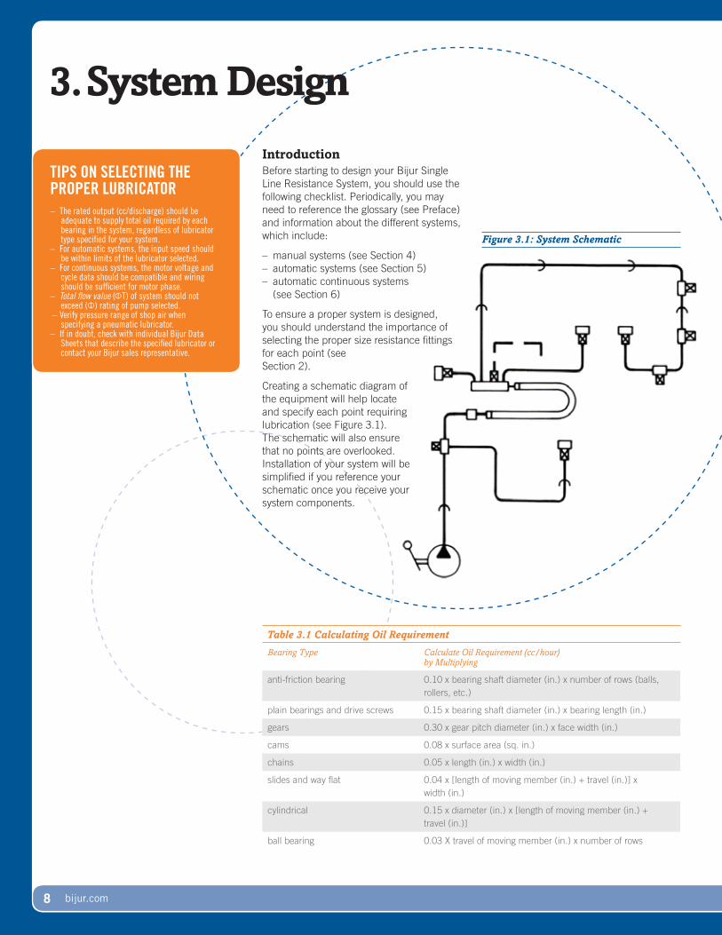
Creating a schematic diagram of the equipment will help locate and specify each point requiring lubrication (see Figure 3.1). The schematic will also ensure that no points are overlooked. Installation of your system will be simplified if you reference your schematic once you receive your system components.
Figure 3.1: System Schematic
Table 3.1 Calculating Oil Requirement
Bearing Type Calculate Oil Requirement (cc/hour) by Multiplying
anti-friction bearing 0.10 x bearing shaft diameter (in.) x number of rows (balls, rollers, etc.)
plain bearings and drive screws 0.15 x bearing shaft diameter (in.) x bearing length (in.)
gears 0.30 x gear pitch diameter (in.) x face width (in.)
cams 0.08 x surface area (sq. in.)
chains 0.05 x length (in.) x width (in.)
slides and way flat 0.04 x [length of moving member (in.) + travel (in.)] x width (in.)
cylindrical 0.15 x diameter (in.) x [length of moving member (in.) + travel (in.)]
ball bearing 0.03 X travel of moving member (in.) x number of rows
TIPS ON SELECTING THE PROPER LUBRICATOR– The rated output (cc/discharge) should be
adequate to supply total oil required by each bearing in the system, regardless of lubricator type specified for your system.
– For automatic systems, the input speed should be within limits of the lubricator selected.
– For continuous systems, the motor voltage and cycle data should be compatible and wiring should be sufficient for motor phase.
– Totalflowvalue (�T) of system should not exceed (�) rating of pump selected.
– Verify pressure range of shop air when specifying a pneumatic lubricator.
– If in doubt, check with individual Bijur Data Sheets that describe the specified lubricator or contact your Bijur sales representative.
bijur.com �
Table 3.2 Recommended Flow Rates for Various System Types
Checklist1. Locate and identify friction points or
types of bearings on the equipment to be lubricated. Determine accurate size and configuration of each bearing point by referring to the machine manual. (Estimate bearing size by visual inspec-tion if manual is unavailable.) At this point, complete your system schematic.
2. Calculate oil requirement (cc/hr) for individual bearing points and record amount next to each point on the schematic. Good lubrication practices demand the oil requirement of each point be calculated separately (see Table 3.1).
3. Calculate total system oil requirement by finding the sum of individual oil requirements (per point). Record the total system oil requirement on your schematic.
4. Select a lubricator that will deliver suffi-cient quantities of oil to the entire system. For this example, a lubricator with a maximum discharge capacity of at least 16 cc/hour is desirable. (See Lubricator Specification tables in Sections 4-6.)
5. Specify resistance fittings for each point in the system.
First, select the proper flow rate for the system type you are designing – continuous loss, cyclic or continuous recirculating (see Table 3.2). Next, assign the sizes of the resistance fittings. Start with the resistance fitting near mid-range in the point that requires the least amount of oil. Continue assigning sizes of all other resistance fittings in the system based on their relative size (discharge volume) to other points. Points that require similar amounts of oil will be supplied from similar sized resistance fittings.
Figure 3.2: Verifying System Capability
To prove that the cyclic system that was just designed is adequate, compare the flow characteristic of each meter unit to the flow value of the overall system. Multiply this ratio to the total pump shot size and you will calculate metered discharge amount per point.
6. Determine total system flow value (�T) by adding the flow value (�) of each resistance fitting. Next, multiply the flow value of each resistance fitting to the number of points in that group (see Figure 3.2).
For cyclic systems: Verify selection of resistance fittings with total system requirement. If total (�) exceeds pump rating (see Table 3.2), select a larger pump or smaller resistance fittings.
For continuous stystems: Determine and specify distribution tubing, fittings, junc-tions and connectors. (See Section 6 to calculate system operating pressure.)
Proving-the-SystemTo prove that the system you designed is adequate, compare the calculated oil discharge with the actual discharge from the lubricator you selected. To do this, divide device flow value by total system flow value, then multiply by pump discharge volume. The result is the actual metered discharge for that point (see Figure 3.2).
CONTINUOUS “LOSS”
CYCLIC “LOSS”
CONTINUOUS “RE-CIRCULATING”
10 bijur.com
Principle-of -OperationBijur’s manual lubricators are operated by activating a piston which is connected to either a push lever or a pull handle.
Manual lubricators contain spring- actuated piston pumps. As the lubricator spring is compressed by actuating the handle, a measured quantity of oil is drawn into the piston chamber. Release of the handle forces the inlet check valve to close and the oil “shot” is forced into the distribution system under pressure of the compressed spring.
When oil is required at lubrication points, raising of lubricator handle
or lowering of push lever will activate the pump, then oil delivery becomes automatic to
each point in the system network.
Every Bijur manual lubricator comes with a filter to prevent contaminants from entering the distribution lines and
reaching points of lubrication.
Select-the-Right-LubricatorBijur offers manual lubricators to meet virtually any industrial lubrication need. Lubricators are available in different combinations that include:
(See Table 4.1 for Lubricator Specifications for Manual Systems.)
Proper selection of a manual lubricator is largely determined by a careful analysis of total system requirements (see Section 3).
Caution: Total sum value of all meter units in a system should not exceed maximum (�T) total for individual pumps. (See Bijur lubricator data sheets at www.bijur.com/Pages/DataSearch.htm for more information.)
4.Manual-Systems
TROUBLESHOOTING MANUAL SYSTEMSSystem condition can be diagnosed by observing the rate of return of the handle or lever on a manual lubricator as follows:
Return Condition
slow, steady normal operation
snaps back or does not return to rest position
clogged filder or broken line
none crushed line
During the discharge cycle of the systems, there should be a maximum peak pressure of 25 psi. (If you experience otherwise, see Section 3: System Design.)
IMPORTANT– Always use meter units (Type F) in cyclic systems
(see Section 2). (Never use continuous operation control units (Type C) in cyclic systems.)
– A single meter unit can supply oil to only one point in the system.
– Always use pressure gauges with finger indicator follower in cyclic systems to observe normal system operating pressure.
Table 4.1 Lubricator Specifications for Manual Systems
Note: Basic Bijur lubricators are listed. Other configurations are available on some models – check individual datasheets. Use Type F meter units with above lubricators.
Figure 4.1: Suitability of Cyclic Pump for Distribution System Meter Units
Complete the following to check that a manual or automatic cyclic pump is not over-extended (too many points) and cannot distribute the required discharge to each point properly.
1. Find various pump discharges based on total number of points (meter units) in the system.
2. Check that total flow value (�T) of all meter units in the system never exceeds the maxi-mum permissible value listed (see Table 3.3).
3. Using the scenario from Figure 3.2, refer to Table 7.1 to determine:
Total System Flow Value (�T) = 85 Maximum permissable value = 750 (based on 10 points at 5cc discharge)
4. This system is within acceptable design specifications.
Meter Units for Cyclic Systems
Flow Rate Flow Value Oil Discharge Rate
3/0 1.2 slow00 2.5 medium slow0 5.01 102 20 medium fast3 40 fast4 805 160 extra, extra fast
NOTES: (1) 5/16-24 for Bijur tapped holes only (2) 5/16-24 for 5/32 tubing connections (3) 1/4-28 for 3/32 tubing connections
NOTES: (1) 1/8 pipe thread
1
�
1
1
�
1
�
1
11
1 1
(See “Bulletin #151” for complete catalog of Bijur specialty fittings.)
1� bijur.com
5.Automatic-Systems
HELPFUL HINTDuring the discharge cycle of the systems, there should be a maximum peak pressure of 25 psi. (If you experience otherwise, see Section 3: System Design.)
IMPORTANT– Always use meter units (Type F) in cyclic systems
(see Section 2). (Never use continuous operation control units (Type C) in cyclic systems.)
– A single meter unit can supply oil to only one point in the system.
– Always use pressure gauges with finger indicator follower in cyclic systems to observe normal system operating pressure.
Principle-of -OperationBijur automatic lubrication systems can be actuated by machine operation or as complete self-contained motorized units. All Bijur cyclic systems utilize meter units to proportion oil to lubrication points through-out the system.
Various system actuation methods are available in automatic systems:
– rotary-driven from machinery or equipment (cyclic)
– self-contained motor-driven with built-in gear reduction (cyclic)
Discharge volume of a “cyclic” lubricator is normally 1.0 or 5.0 cubic centimeters. A gear pump can range from 167cc/min - 500cc/min. Typically, oil volume may be reduced by 50% depending on
the application. Larger discharge amounts are also available if required. Contact your Bijur sales engineer for recommendations and procedures.
The lubrication operational cycle is normally a function of machinery size and
number of points.
A quick-feed activator is normally supplied on the
lubricator to rapidly fill distribution tubing after installation and to verify
operation at any time.
Select-the-Right-LubricatorVarious discharge cycles are available to meet most industrial lubrication needs. Steps should be taken to ensure that the lubrication system does not become over-extended. Proper selection of an automatic cyclic lubricator is largely determined by a careful analysis of total system requirements (see Section 3).
(See Table 5.1 for Lubricator Specifications for Automatic Systems.)
In special situations in which larger output cyclic discharge systems are required, please contact your Bijur sales representative.
Note: Electronic cycle pressure monitors are available to safeguard the system (see Data Sheet 2673 at www.bijur.com/Pages/DataSearch.htm for more information).
Table 5.1 Lubricator Specifications for Automatic Systems
Type Max. Flow Value (�T)
Method of Operation
Delivery Max. Discharge
Pressure (psi)
Approx. No. Points Served
Reservoir Capacity
Part Number
Datasheet Pump Type
AA 900 rotary/motor adjustable 32.0cc/shot > 200 10-200 optional various 2001 gear
AB 900 rotary/motor adjustable 32.0cc/shot > 200 10-200 optional various 2001 gear
TM-1 100 motor adjustable 1.0cc/shot 25-50 1-20 1 pint, 1 liter various 21383 piston
Note: Basic Bijur lubricators are listed. Other configurations are available on some models – check individual datasheets. Use meter units with above lubricators.*Max flow value varies by application. Contact Bijur for assistance in system setup.
Figure 4.1: Suitability of Cyclic Pump for Distribution System Meter Units
Complete the following to check that a manual or automatic cyclic pump is not over-extended (too many points) and cannot distribute the required discharge to each point properly.
1. Find various pump discharges based on total number of points (meter units) in the system.
2. Check that total flow value (�T) of all meter units in the system never exceeds the maxi-mum permissible value listed (see Table 3.3).
3. Using the scenario from Figure 3.2, refer to Table 7.1 to determine:
Total System Flow Value (�T) = 85 Maximum permissable value = 750 (based on 10 points at 5cc discharge)
4. This system is within acceptable design specifications.
Meter Units for Cyclic Systems
Flow Rate Flow Value Oil Discharge Rate
3/0 1.2 slow00 2.5 medium slow0 5.01 102 20 medium fast3 40 fast4 805 160 extra, extra fast
NOTES: (1) 5/16-24 for Bijur tapped holes only (2) 5/16-24 for 5/32 tubing connections (3) 1/4-28 for 3/32 tubing connections
1
�
1
1
�
1
11
1 1
FJB Flow Rate Part #
3/000012345
B-6548B-2494B-2495B-2496B-2497B-2498B-2499B-2500
1
�
SureFire
(See “Bulletin #151” for complete catalog of Bijur specialty fittings.)
NOTES: (1) 1/8 pipe thread
1� bijur.com
LOSS vs RECIRCULATINGA continuous loss system delivers a constant, relatively small amount of oil to the bearings. The oil is not recovered after delivery and is lost for further use.
On the other hand, a continuous recirculating system delivers a steady, controlled flow of oil to bearings. After leaving the bearing, the oil is collected and re-directed back to the pump for reuse.
IMPORTANTAlways use control units (Type C) in continuous systems (see Section 2). (Never use cyclic operation meter units [Type F] in continuous systems.)
HELPFUL HINTIn the main feed line between the pump outlet and the first control unit, a pressure filter (such as part number 19848) must be incorporated to prevent clogged control units.
Always use pressure gauges to observe system operating pressure.
Principle-of -OperationBijur’s continuous lubricators deliver a constant feed of oil to lube points, permitting a uniform coating of oil to protect the friction point. The lubricators may be driven by machine shaft or powered by self-contained electric motor units.
Lubricators are available to deliver either constant (nominal) volume output or constant pressure output.
Normally, continuous lubricators are rotary-driven gear pumps which are fully submerged in oil at the bottom of a reservoir and protected by a coarse metal suction screen.
Operating pressure is limited to 100 or 200 psi by a built-in relief valve. Discharge from the pump is controlled
by a bypass valve.
Several size reservoirs (plastic or metal) are available. Also available are pressure monitors and low level oil switchs.
Setting-the--System-Pressure
After the system is fully primed and warmed up, adjust the bypass valve
setting at the lubricator to the system operating pressure (see Figure 6.1).
After a prolonged shutdown, the initial operating pressure may register higher than previously set. Do not re-adjust. The pressure will revert back to its original setting after it warms up.
6.Automatic-Continuous-Systems
Table 6.1 Control Units for Continuous Systems
Flow Rate Flow Value Relative Discharge Rate
5/0 0.3 extra, extra slow4/0 0.63/0 1.2 slow00 2.5 medium slow0 5.01 10.02 20.0 medium fast3 40.0 fast4 80.05 160.0 extra, extra fast
Table 6.1 Lubricator Specifications for Automatic Continuous Systems
Type Max. Flow Value (�T)
Method of Operation
Delivery Max. Discharge (cc/min)
Pressure (psi)
Approx.No. Points Served
Reservoir Capacity
Part Number
Datasheet Pump Type
AO see note rotary/motor adjustable 50.0 > 200 100 optional various 2075 gear
V5B see note motor adjustable 125.0 100 or 200 200 0.5 gallon various 2163 gear
V5C see note motor adjustable 125.0 100 or 200 200 sump mounted various 2164 gear
V5W see note motor adjustable 125.0 100 or 200 200 1 gallon various 24064 gear
V3 see note motor adjustable 3.0 100 or 200 20 1 liter 24759, 24760 gear
Gear Pump
see note motor non-adjustable 50.0 > 100 200 sump mounted 24795, 24796 gear
Note: Basic Bijur lubricators are listed. Other configurations are available on some models – check individual datasheets. Use control units with above lubricators.For breakdown of permissable “� values” for various numbers of points, see individual datasheets.
bijur.com 1�
Figure 6.1 Determine System Pressure
List and calculate the individual oil requirements as described in Section 3. The system pressure setting required to obtain the required discharge or flow can be calculated from the following formula:
P = FV/�, where:
P = pressure at operating temperature
F = Total required (or calculated) flow in cubic centimeters per minute (cc/min)
V = Viscosity of oil in system at operating temperature measured in Saybold Seconds Universal (SSU)
� = Total flow (�T) of system
For example:A system has 20 points, all No. 0 rate control units and a total discharge of 5 cc/min. A 1000 SSU oil @ 100˚F is used in the system.
P = 5 x 1000 ÷ 100
P = 50 psi
Put another way, each point in this system will be receiving 0.25 cc/min at a continuous working pressure of 50 psi. For additional system design information, please refer to engineering manual.
Type V5W
Lubricators
Control-Units
Straight Mounting Junction Mounting
Tee Mounting
NOTES: (1) 1/8 pipe thread (2) 5/16 for 5/32 tubing connections NOTES: (1) 5/16-24 for Bijur tapped holes only (2) 5/16-24 for tubing connections (3) 1/4-28 for 3/32 tubing connections
(See “Bulletin #151” for complete catalog of Bijur specialty fittings.)
Note: Reservoirs are sold seperately.
1� bijur.com
Figure 7.1: Compression Bushing
Figure 7.2: Compression Nut
PRIMING THE SYSTEMAfter installation, fill the pump reservoir with recommended oil and then prime the system as follows:
1. Disconnect main line connection at a resistance fitting located mid-way in the distribution system
2. Actuate the pump manually or automatically to expel air from the system to that point
3. Reconnect the fitting4. Select a tube fitting connection at the farthest
point in the distribution system from the pump and actuate the lubricator as above to prime the system and expel air
5. Reconnect the fitting6. Repeat as necessary at other points
Good preventative maintenance procedures for Cyclic and Continuous pumps include annually inspecting and changing suction filters and screens.
Principle-of -OperationAll Bijur Resistance Systems – manual, cyclic and continuous – operate at pressures ranging from 25-200 psi. The distribution network connects the lubricator to each application point. Typically, 5/32” diameter tubing is adequate to deliver oil to all connected points. (Small and large diameter tubing is available for systems in different sized areas.) Monitor system operation with optional pressure gauges and automatic pressure switches.
System-AssemblyBijur compression nut connections or compression bushing connections are necessary to connect tubing to the various parts of the lubrication system (see Figure 7.1 and Figure 7.2).
To obtain oil tight connections, cut tubing end squarely and assemble (see Figure 7.1 and Figure 7.2). The end of tubing must be firmly seated in the mounting shoulder, then complete the assembly by turning bushing or nut 2-3 full turns after finger tight.
7.Distribution-Network
TUBING 5/32” O.D.
COMPRESSION BUSHING B-1371
COMPRESSION SLEEVE B-8272 NYLON B-1061 METAL
TAPPED FITTING BIJUR TAPPED HOLE
5/16-24
TUBING 5/32” O.D.
COMPRESSION NUT B-1095
COMPRESSION SLEEVE B-8272 NYLON B-1061 METAL
THREADED FITTING 5/16-24
Table 7.1 Cyclic System Discharge – Number of Meter Units vs. Maximum System Flow Value (For meter units – Type F with minimum viscosity 100 SSU)
Total Number of Meter Units
in System
Total Oil Discharge (cc/shot or cycle) Shaded Area Represents Maximum System Flow Value
SYSTEM OPERATION AND MONITORINGBijur Single Line Resistance Systems are designed to operate at relatively low pressures. Recommended pressure for resistance systems is indicated at right.
A pressure gauge should be installed in the main line as far from the lubricator as practical. To help ensure trouble-free performance, consult Bijur engineering data aheet for proper operating pressure ranges for the installed system.
used to make oil tight connections at the following:
– resistance fittings: meter units (Type FSA and FJB) and control units (Type CSA and CJB)
– male connections (5/16-24 NF): typically lubricator outlets and adapters
A compression sleeve (B-1061 for metal tubing or B-8272 for nylon tubing) is required with each nut to make an oil tight connection (see Figure 7.2). The assembly technique is similar to that used for compression bushings.
Use proper fittings because the system is under pressure during operation and leak-free connections are essential to prevent leakage and system pressure drop.
Bearing mounted flow units (Types FSA and CSA) utilize a compression nut to provide a convenient and reusable connection for replacement of resistance fittings (see Figure 7.3).
A compression bushing is necessary when mounting a resistance fitting directly at the bearing with a tee adapter (see Figure 7.4).
All junction block connections utilize a compression bushing that help ensure tight tubing connections to junctions and that easily adapt to machine contours (see Figure 7.5).
When-to-Use-Compression-Bushing-ConnectionsCompression Bushings (B-1371) are used to make oil tight connections at the following:
– junctions and junction bars– tee headers (meter units and
control units)– adapters
A compression sleeve (B-1061 for metal tubing or B-8272 for nylon tubing) is required with each bushing to make an oil tight connection (see Figure 7.1).
To assemble a tubing connection, the compression bushing is first slipped over the end of the 5/32” tubing (metal or nylon), followed by a suitable compression sleeve. As the bushing is threaded to the female threaded connection, the sleeve is permanently crimped to the tubing, simultaneously making a reusable oil tight connection.
DISTRIBUTION COMPONENTS
Part # Description
Tubing brass, copper, steel or nylon
5/32”
brass, copper, steel or nylon
3/32”
Tubing clips A-2425 Single
B-3539 Double
Flexible Hoses
B-3134 6”
B-3433 8”
B-3145 10”
B-3135 12”
B-3530 14”
B-3531 16”
Junctions B-3288 2-Way (2 outlets)
B-3065 3-Way
B-4231 4-Way
Junction-Single
B-3262 4-Way Single (4 outlets)
B-3263 5-Way Single
B-3264 6-Way Single
Junction-Double
B-3109 6-Way Double (6 outlets)
B-3253 8-Way Double
B-3254 10-Way Double
Closure Plug B-3784
Connectors A-3920 Straight
A-2768 90° Elbow
B-3133 45° Elbow
Adapters A-2835 Straight
A-3080 90’ Elbow
Compression Sleeve
B-1061 Metal -5/32 Tubing
B-8272 Nylon
Compression Bushing
B-1371 5/32 Tubing
Compression Nut
B-1095
Pressure Gauges
B-3841 30 psi
B-5611 100 psi
B-4582 200 psi
Filters B- 7239 25µ (3 “)
B-7254 25µ (5 “)
Figure 7.4: Tee Mounting
Figure 7.5: Junction Mounting
1� bijur.com
HELPFUL HINTAdditional technical information about Single Line Resistance lubricators and components are available at www.bijur.com.
The information contained in Bijur’s EngineeringDataSheets and ServiceInstructionSheets will help ensure trouble-free system operation and a long life for your equipment.
Installation-TipsBe sure to mount the lubricator in an accessible area so the reservoir may be replenished with oil without stopping the machine or endangering the operator.
Always run main distribution lines as straight as possible along the contours of the machinery to be lubricated. Avoid sharp bends and moving equipment.
Keep branch and secondary lines as short as possible by placing junctions close to any lubrication point clusters.
Ordering-TipsTo assist in identifying system components, a Bill of Materials checklist has been provided (see opposite page). Fill in your final selections in the Bill of Materials as you complete each section of this brochure.
Upon completing the Bill of Materials you will be able to specify the necessary items and order your Bijur Single Line Resistance System.
8.Installation-&-Mounting
NEED HELP?Are you in doubt about any part of designing, speci-fying or ordering your Bijur Single Line Resistance System? For help, copy your BillofMaterials check-list and send it to your Bijur sales representative.
FSA-1 TABLE WAY
FJB-0 SADDLE
FTG-1 VERTICAL WAY
TYPE L5P LUBRICATOR
FTD-1 TABLE WAY
FTA-1 TABLE WAY
FTD-1 SADDLE WAY
FSA-1 TABLE WAY
14” HOSE ASSEMBLY
FSA-1 VERTICAL WAY
SAMPLE BILL OF MATERIALS
QTY Bijur Part # Description
1 D-3174 L5P-R Lubricator
4 B-1084 FSA-1
1 B-2495 FJB-0
1 B-1072 FTA-1
2 B-1107 FTD-1
1 B-2761 FTG-1
1 B-3065 Junction
1 B-3264 Junction
2 B-3784 Plug
1 B-3530 Hose Assembly
4 A-2768 Elbow
6 A-2435 Clip
24 5B25 5/32 Tubing
6 B-1095 Nut
20 B-1371 Bushing
26 B-1061 Sleeve
bijur.com 1�
EqUIPMENT TYPE MANUFACTURER MODEL NUMBER
Bill-of-Materials
System-Type
Cyclic (Manual)
Cyclic (Automatic)
Continuous
Resistance-Fittings
Qty Type Flow Rating
(e.g.) 4 FSA 1
Total Qty (must equal total number of points)
Total # of lubrication point:
Enter points per type:
anti-friction
ball bearing cam
chain
cylindrical
flat
gears
plain
roller
slides/way
Lubricator
Manual
L2P L5P L18P HAP-P HIP-P KIB KIC
Automatic
AA AB TM-1 TM-5 YP-8 SureFire
Automatic Continuous
AO V5B V5C V5W V3
< Check only one lubricator.
< Choose from following list for “Type” column:
Manual&CyclicStraight:FSAFTTee:FTAFTCFTGFTD
Junction:FJBFJD
ContinuousStraight:CSACTTee:CTACTCCTGCTD
Junction:CJBCJD
Distribution-Fittings
Description Qty
Tubing (circle one): copper, brass, steel or nylon ft.
Tubing Clips (circle one): single or double
Flexible Tubing (specify length):
Junctions (circle one): regular, single or double
Connectors (circle one): straight, 90º elbow or 45º elbow
NOTE: See “Bulletin #151” for complete catalog of Bijur specialty fittings.
�0 bijur.com
YOUR LOCAL DISTRIBUTOR
B258 (06-23)
Innovators-of -engineered-lubrication--technology-since-1923Sometimes you know what kind of lubrication system you need. Sometimes you don’t. Bijur has experienced regional sales managers that can walk you through the process of selecting a system that fits your needs when you aren’t sure. And when you need additional parts for the system, our trained customer service representatives can help you choose genuine Bijur parts that can generally be shipped to you within 24 hours.
Bijur also has ISO 9001:2000 quality certified manufacturing facilities around the world, so you’ll know your centralized lubrication system meets the highest industry quality standards. It’s all part of the Bijur commitment to quality and customer service.
CORPORATE HEADQUARTERSBijur Delimon International 808 Aviation Parkway, Suite 1400 Morrisville, NC 27560