A nvfessional frostsp~rnable .oble .3.665 meter/ I2'AFC .~atellite dishKithfnilyredundant, broadcast nerrified eleetronics-Receives Cband or KU band -fullor '/: trmsponder. Note: Operatorisbilled at standod technician note.:Pricefor Mpls. / St. Paul locationsper day
SITE SURVEYS. . . . . . . . : :
:: :
. . .
.z50:o0Cor KV band in 7caro.
PROGRAM RECORDING. ... : . . . . . . . ealfforcor KU blind
Magnetic Attractions(1) Horseshoe Magnet . T/2-pound pulllAbout 11/2x11/8x'/A. 64-1887 . . 7.99(2) Rare-Earth Super-Magnet. Powerful,yetonly 1/4" diameter. 64-1895, Palf 1.49(3) Magnetic Tape. Holds tools to walland more. '/2" x 30". 64-1890 . . . . . . 990(4) High-Energy Ceramic Magnet. About1 1/8 x '/e x 3/e". 64-1877
. . . . . . . . . . . 996
(5)(6)(7) Ceramic Magnets . . . . Each 236
Type
Cat No. 11-24 26-99 100-Up
1 1 /' R
d
64
5Re=n1'
'/z Button
w-leeo 20i 191
171our 7_18B Each Each Each9. 641875
(3) TwoSanTerminate With Phone Jack . ideal forreplacingjacks on speakers,antenna,in ut on radios,or use on projects. 274-620 . . . . . . . ;- et 211.59(4) Five-Lug Tie Points . Use center lugfor groundinwhen used onmetal chassis. 274-688, Pkg. et 411.2
M (e). .(1) IMI m) ttal fW
14
fl4)
(tat
pal
tnl
Ctal
ttal
` ,, (291
(r) (M (ta) (24) (2a)
W)Ilk~
t ., .
Hardware and
Connectors in
Handy-Pales.
Only $1.39 Each
r~(4)
d 120
! (e) (9)
'For use with our MEGACABLEO speaker wire-see page 116.
THOUSANDSOF ELECTRONIC PARTSANDACCESSORIES AREAVAILABLE THROUGH OURFASTSPECIAL-ORDER SERVICE-SEE PAGE 106
NOTICE : Equipment subject to minor appearance changes.
FEATURES-The KODAK EKTAGRAPHIC Slide Projector, Model AF-2 (Auto-
matic Focus), has been designed for professional slide presentations .
One of the valuable features of this projector is the automatic focusingdevice which keeps each slide in focus throughout its projection . You willfind the projector to be an exceptionally durable, dependable audiovisualdevice-versatile, easy to operate, efficient in its functions . The featuresthat distinguish your projector are these:" Automatic focusing is accomplished by a built-in electronic control .
" A choice of three Kodak trays is available for use with the Model AF-2
Projector. Each tray has convenient slide identification numbers.
" The KODAK CAROUSEL* Universal Slide Tray, furnished with the pro-
jector, has an 80-slide capacity and accepts glass and cardboard slides
up to 1/g inch thick. (The projector will also accommodate the KODAK
CAROUSEL 80 Slide Tray and the KODAK CAROUSEL 140 Slide Tray .)
" Any transparency format in a 2 x 2-inch mount can be projected, in-cluding 126-size (26.5 x 26.5mm), 135-size (22.9 x 34.2mm), 828-size(26.2 x 38mm), 127-size (38 x 38mm), and 110-size (12 x 15.8mm)transparencies in 2 x 2-inch mounts or KODAK 2 x 2 Adapters for 110Slides ." A timer in the projector provides automatic changing of slides for5-, 8-, or 15-second periods. Split-second intervals between slides
eliminate long dark-screen periods." Slides can be projected in forward or reverse sequence or as individ-ually selected ." A remote control with a 12-foot cord gives forward, reverse, and
focusing control away from the projector. Extension cords (see page 10)
can be added if needed ." Focus shift of the projected image is minimized because all slides are
conditioned by warm air before projection ." Precise horizontal and vertical positioning of each slide is provided .
As a result, screen images from two of these projectors can be exactly
superimposed . Accurate image registration depends upon carefullymounted transparencies ." The illuminated control panel includes a 4-position Selector Switch
for OFF, FAN, and LOW and HIGH light output ." Noise is minimized by low blower speed." Elevation and leveling controls are provided ." The 300-watt ELH lamp produces less heat than a 500-watt CBA lamp,
but offers equivalent light output ." A lamp ejector lever simplifies lamp replacement ." The heat-absorbing glass and condenser lens are held in place in-
dependently of any other mechanism . This means that a new lamp can
be installed without danger of accidentally displacing these optics .
" The projector is wired to accommodate the KODAK CAROUSEL DissolveControl and other plug-in accessories (see page 10) .
*All CAROUSEL equipment mentioned in this manual can be used with the KODAK
EKTAGRAPHIC Slide Projector, Model AF-2 .
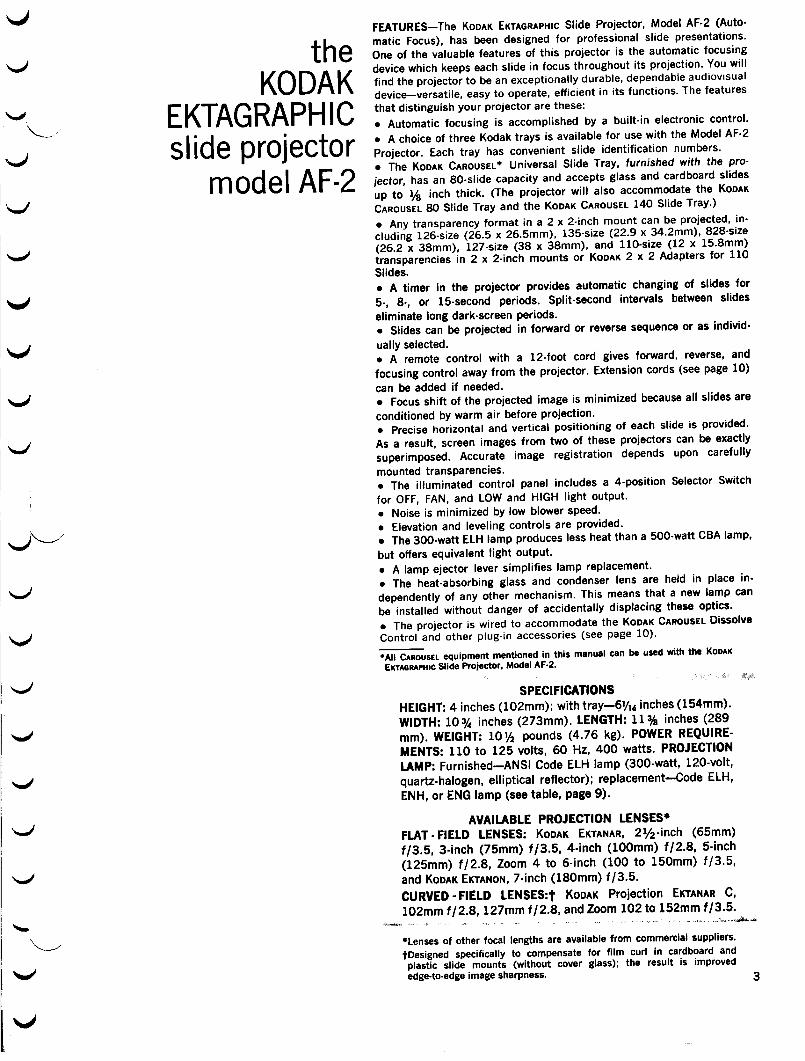
SPECIFICATIONSHEIGHT: 4 inches (102mm); with tray-61/16 inches (154mm).
*Lenses of other focal lengths are available from commercial suppliers.tDesigned specifically to compensate for film curl in cardboard andplastic slide mounts (without cover glass) ; the result is improvededge-to-edge image sharpness. 3
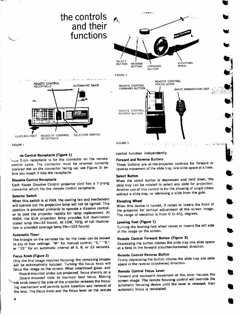
FIGURE 1
4
REMOTE CONTROLRECEPTACLE
AUTOMATIC TIMER
the controlsand theirfunctions
LEVELING FOOT
DISSOI VF CONTROL
SELECTOR SWITCHRECEPTACLE
1te Control Receptacle (Figure 1)5-pin receptacle is for the connector on the remote-
control cable. The connector must be oriented correctly
(colored dot on the connector facing up, see Figure 3) be-
fore you insert it into the receptacle .
Dissolve Control ReceptacleEach KODAK Dissolve Control projector cord has a 7-prong
connector which fits the remote control receptacle .
Selector SwitchWhen this switch is at FAN, the cooling fan and mechanism
will operate but the projection lamp will not be lighted . This
position is provided primarily to operate a dissolve control,
or to cool the projector rapidly for lamp replacement. At
HIGH, the ELH projection lamp provides full illumination
(rated lamp life-35 hours) . At LOW, 70% of full illumina-
tion is provided (average lamp life-105 hours) .
Automatic TimerThe triangle on the serrated bar for the timer can be moved
to any of four settings : "M" for manual control ; "5," "8,"
or "15" for an automatic interval of 5, 8, or 15 seconds.
Focus Knob (Figure 2)Only the first image requires focusing; the remaining imageswill be automatically focused. Turning the focus knob will
focus the image on the screen . When intermixed glass- and
-aboard-mounted slides are projected, focus sharply on a
Jboard-mounted slide to maintain best focus . Moving
-me knob toward the side of the projector releases the focus-
ing mechanism and permits quick insertion and removal of
the lens . The focus knob and the focus lever on the remote
FIGURE 2
FIGURE 3
SELECTBUTTON REVERSE
BUTTON FORWARD
WHEELBUTTON
control function independently .
REMOTE CONTROLFOCUS LEVER
Forward and Reverse ButtonsThese buttons are at-the-projector controls for forward or
reverse movement of the slide tray, one slide space at a time .
Select ButtonWhen the select button is depressed and held down, the
slide tray can be rotated to select any slide for projection .
Another use of this control is for the showing of single slides
without a slide tray, or retrieving a slide from the gate .
Elevating WheelWhen this device is turned, it raises or lowers the front of
the projector for vertical adjustment of the screen image.
The range of elevation is from 0 to 61/2 degrees.
Leveling Foot (Figure 1)Turning the leveling-foot wheel raises or lowers the left side
of the image on the screen .
Remote Control Forward Button (Figure 3)
Depressing the button rotates the slide tray one slide space
at a time in the forward (counterclockwise) direction .
Remote Control Reverse ButtonFirmly depressing the button rotates the slide tray one slide
space in the reverse (clockwise) direction .
Remote Control Focus LeverForward and backward movement of this lever focuses the
screen image. The remote focusing control will override the
automatic focusing device until the lever is released, then
automatic focus is reinstated .
SCREEN AND SEATS3ecause slides may be horizontal, vertical, or square, asquare screen is most desirable. It should be large enoughfor easy viewing by everyone present and (for most installa-tions) should be at the same level as, or higher than, theprojector.
For best results with most slides, the rear row of seatsshould not be farther from the screen than eight times theprojected image height . Seats should be placed as closeas possible to both sides of the beam thrown by the projec-
tor. The screen image will appear most realistic to the per-sons seated near the projector beam .
USING THE ZOOM LENSThe KODAK EKTANAR Zoom Lens, 4 to 6-inch f/3.5, lets youvary the size of the projected image without moving eitherthe projector or the screen . By this means, you can fill thescreen at any normal projector-to-screen distance within the
range of the lens .To use the zoom lens-
a. Focus the image on the screen by turning the focus knob.
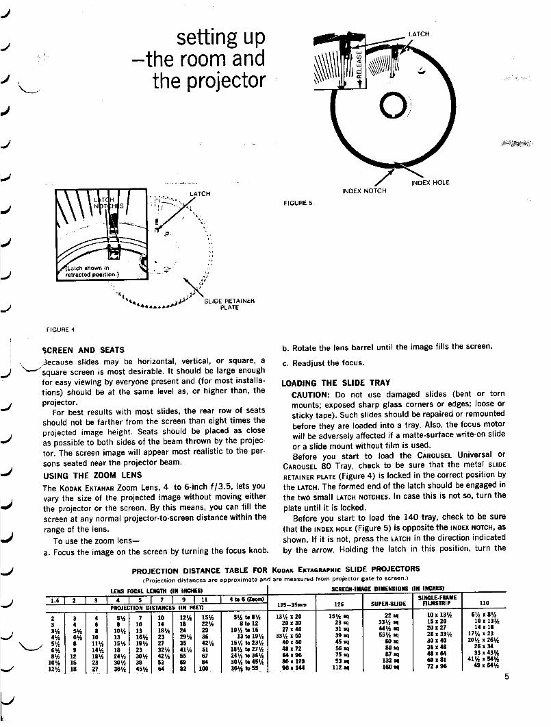
setting u pthe room andthe projector
SLIDE RETAINERPLATE
FIGURE 5
c . Readjust the focus.
INDEX NOTCH
b. Rotate the lens barrel until the image fills the screen .
LOADING THE SLIDE TRAYCAUTION: Do not use damaged slides (bent or tornmounts ; exposed sharp glass corners or edges; loose orsticky tape) . Such slides should be repaired or remountedbefore they are loaded into a tray . Also, the focus motorwill be adversely affected if a matte-surface write-on slideor a slide mount without film is used .Before you start to load the CAROUSEL Universal or
CAROUSEL 80 Tray, check to be sure that the metal SLIDE
RETAINER PLATE (Figure 4) is locked in the correct position bythe LATCH. The formed end of the latch should be engaged inthe two small LATCH NOTCHES. In case this is not so, turn the
plate until it is locked .Before you start to load the 140 tray, check to be sure
that the INDEX HOLE (Figure 5) is opposite the INDEX NOTCH, as
shown. If it is not, press the LATCH in the direction indicatedby the arrow. Holding the latch in this position, turn the
PROJECTION DISTANCE TABLE FOR KODAK EKTAGRAPHIC SLIDE PROJECTORS
(Projection distances are approximate and are measured from projector gate to screen .)
LENS FOCAL LENGTH (IN INCHES)
I
SCREEN-IMAGE DIMENSIONS (IN INCHES)
5
3 4 5 7PROJECTION DISTANCES
9 11(IN FEET)
4 to 6 (Zoom)135-35mm I 126 I SUPER-SLIDE I SINGLE-FRAME
110
4 5% 7 10 121/2 15% 52A to St/2 13 1/1 x 20 15 1A sq 22 sq 10 x 13% 61/2 x 86 8 10 14 18 222/1 8 to 12 20 x 30 23 sq 331/2 54 15x20 10 x 132/18 10% 13 18 1/2 24 29 101/2 to 16 27x40 31 sq 441/2 $q 20 x 27 14 x 1810 13 161/2 23 29% 36 13 to 19 1/2 33% x 50 39 xq 551/2 sq 26 x 33 1/1 17 1h x 23111/2 151/2 19% 27 35 42% 151/2 to 231/2 40 x 60 45 sq 60 sq 30 x 40 201/2 x 261/2
141/2 18 23 321/2 41% 51 18 2/1 to 27 1/1 48x72 56 sq 80 sq 36x48 26 x 3418% 241/2 30'A 42 1/2 55 67 241/2 to 361/2 64 x 96 75 sq 87 sq 48 x 64 33 x 431/223 301/2 38 53 69 84 301/2 to 45 2/1 801120 93 sq 132 sq 60x81 41 2/1 x 54 1/227 361/2 451/2 64, 82 100 36% to 55 96 x 144 112 sq 160 sq 72 x 96 49x6412
6
FIGURE 6
FIGURE 7
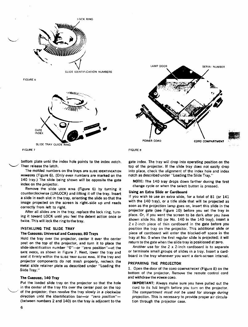
LOCK RING
SLIDE IDENTIFICATION NUMBERS
bottom plate until the index hole points to the index notch.Then release the latch.The molded numbers on the trays are SLIDE IDENTIFICATION
NUMBERS (Figure 6) . (Only even numbers are marked on the140 tray .) The slide being shown will be opposite the gateindex on the projector.
Remove the slide LOCK RING (Figure 6) by turning itcounterclockwise (UNLOCK) and lifting it off the tray . Inserta slide in each slot in the tray, orienting the slide so that theimage projected on the screen is right-side up and readscorrectly from left to right.
After all slides are in the tray, replace the lock ring, turn-ing it toward LOCK until you feel the detent action once ortwice. This will lock the ring to the tray .
INSTALLING THE SLIDE TRAYThe CAROUSEL Universal and CAROUSEL 80 TraysHold the tray over the projector, center it over the centerpost on the top of the projector, and turn it to place theslide-identification number "0"-or "zero position"-at theGATE INDEX, as shown in Figure 7 . Next, lower the tray andseat it firmly within the SLIDE TRAY GUIDE RING . If the tray andprojector components do not mesh properly, recheck themetal slide retainer plate as described under "Loading theSlide Tray."
The CAROUSEL 140 TrayPut the loaded slide tray on the projector so that the holein the center of the tray fits over the center post on the topof the projector; then revolve the tray slowly in a clockwisedirection until the identification bar-or "zero position"-(between numbers 2 and 140) on the tray is adjacent to the
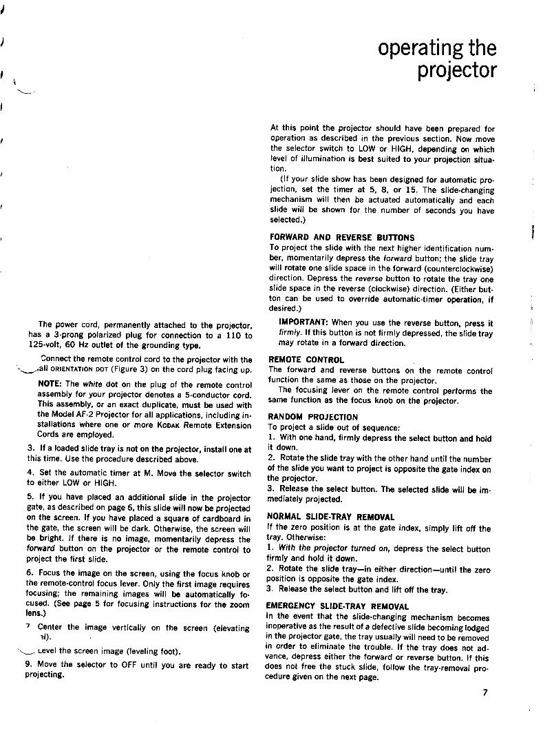
FIGURE 8
POWER CORD
CORD COMPARTMENT
gate index. The tray will drop into operating position on thetop of the projector. If the slide tray does not easily dropinto place, check the alignment of the index hole and indexnotch as described under "Loading the Slide Tray."
NOTE: The 140 tray drops down farther during the firstchange cycle or when the select button is pressed.
Using an Extra Slide or CardboardIf you wish to use an extra slide, for a total of 81 (or 141with the 140 tray), or a title slide that will be projected assoon as the projection lamp goes on, insert this slide in theprojector gate (see Figure 10) before you set the tray inplace. Or, if you want the screen to be dark after you haveshown slide No . 80 (or No. 140 in the 140 tray), insert a2 x 2-inch piece of thin cardboard in the gate before youposition the tray on the projector. This additional slide orpiece of cardboard will enter the blocked-off space in thetray at No . 0 when the first regular slide is projected; it willreturn to the gate when the slide tray is positioned at zero .
Another use for the 2 x 2-inch cardboard is to separateor terminate small groups of slides in a tray . Insert a card-board in the tray whenever you want a dark-screen interval .
PREPARING THE PROJECTOR1. Open the door of the CORD COMPARTMENT (Figure 8) on thebottom of the projector. Remove the remote control cordand withdraw the POWER CORD .
IMPORTANT: Always make sure you have pulled out thecord to its full length before you turn on the projector.The compartment must not be used for storage duringprojection . This is necessary to provide proper air circula-tion through the projector case .
The power cord, permanently attached to the projector,has a 3-prong polarized plug for connection to a 110 to125-volt, 60 Hz outlet of the grounding type .
Connect the remote control cord to the projector with theall ORIENTATION DOT (Figure 3) on the cord plug facing up .
NOTE : The white dot on the plug of the remote controlassembly for your projector denotes a 5-conductor cord .This assembly, or an exact duplicate, must be used withthe Model AF-2 Projector for all applications, including in-stallations where one or more KODAK Remote ExtensionCords are employed .
3.
If a loaded slide tray is not on the projector, install one atthis time . Use the procedure described above.4. Set the automatic timer at M. Move the selector switchto either LOW or HIGH .5. If you have placed an additional slide in the projectorgate, as described on page 6, this slide will now be projectedon the screen . If you have placed a square of cardboard inthe gate, the screen will be dark. Otherwise, the screen willbe bright . If there is no image, momentarily depress theforward button on the projector or the remote control toproject the first slide.6. Focus the image on the screen, using the focus knob orthe remote-control focus lever. Only the first image requiresfocusing ; the remaining images will be automatically fo-cused. (See page 5 for focusing instructions for the zoomlens .)
Center the image vertically on the screen (elevating
Level the screen image (leveling foot).9. Move the selector to OFF until you are ready to startprojecting .
operating theprojector
At this point the projector should have been prepared foroperation as described in the previous section. Now movethe selector switch to LOW or HIGH, depending on whichlevel of illumination is best suited to your projection situa-tion .
(If your slide show has been designed for automatic pro-jection, set the timer at 5, 8, or 15 . The slide-changingmechanism will then be actuated automatically and eachslide will be shown for the number of seconds you haveselected .)
FORWARD AND REVERSE BUTTONSTo project the slide with the next higher identification num-ber, momentarily depress the forward button ; the slide traywill rotate one slide space in the forward (counterclockwise)direction. Depress the reverse button to rotate the tray oneslide space in the reverse (clockwise) direction . (Either but-ton can be used to override automatic-timer operation, ifdesired.)IMPORTANT: When you use the reverse button, press itfirmly . If this button is not firmly depressed, the slide traymay rotate in a forward direction.
REMOTE CONTROLThe forward and reverse buttons on the remote controlfunction the same as those on the projector.
The focusing lever on the remote control performs thesame function as the focus knob on the projector.
RANDOM PROJECTIONTo project a slide out of sequence :1 . With one hand, firmly depress the select button and holdit down .2. Rotate the slide tray with the other hand until the numberof the slide you want to project is opposite the gate index onthe projector.3. Release the select button . The selected slide will be im-mediately projected.
NORMAL SLIDE-TRAY REMOVALIf the zero position is at the gate index, simply lift off thetray. Otherwise:1 . With the projector turned on, depress the select buttonfirmly and hold it down .2. Rotate the slide tray-in either direction-until the zeroposition is opposite the gate index.3 . Release the select button and lift off the tray .
EMERGENCY SLIDE-TRAY REMOVALIn the event that the slide-changing mechanism becomesinoperative as the result of a defective slide becoming lodgedin the projector gate, the tray usually will need to be removedin order to eliminate the trouble. If the tray does not ad-vance, depress either the forward or reverse button . If thisdoes not free the stuck slide, follow the tray-removal pro-cedure given on the next page.
servicing theprojector
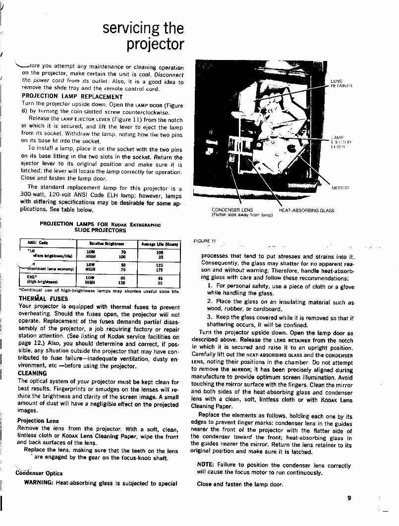
`,_flore you attempt any maintenance or cleaning operationon the projector, make certain the unit is cool . Disconnectthe power cord from its outlet . Also, it is a good idea toremove the slide tray and the remote control cord .PROJECTION LAMP REPLACEMENTTurn the projector upside down . Open the LAMP DOOR (Figure8) by turning the coin-slotted screw counterclockwise .
Release the LAMP EJECTOR LEVER (Figure 11) from the notchin which it is secured, and lift the lever to eject the lampfrom its socket . Withdraw the lamp, noting how the two pinson its base fit into the socket .
To install a lamp, place it on the socket with the two pinson its base fitting in the two slots in the socket . Return theejector lever to its original position and make sure it islatched; the lever will locate the lamp correctly for operation.Close and fasten the lamp door.
The standard replacement lamp for this projector is a300-watt, 120-volt ANSI Code ELH lamp ; however, lampswith differing specifications may be desirable for some ap-plications . See table below.
PROJECTION LAMPS FOR KODAK EKTAGRAPHICSLIDE PROJECTORS
*Continual use of high-brightness lamps may shorten useful slide life.
THERMAL FUSESYour projector is equipped with thermal fuses to preventoverheating . Should the fuses open, the projector will notoperate. Replacement of the fuses demands partial disas-sembly of the projector, a job requiring factory or repairstation attention . (See listing of Kodak service facilities onpage 12.) Also, you should determine and correct, if pos-sible, any situation outside the projector that may have con-tributed to fuse failure-inadequate ventilation, dusty en-vironment, etc -before using the projector.CLEANINGThe optical system of your projector must be kept clean forbest results . Fingerprints or smudges on the lenses will re-duce the brightness and clarity of the screen image. A smallamount of dust will have a negligible effect on the projectedimages .
Projection LensRemove the lens from the projector. With a soft, clean,lintless cloth or KODAK Lens Cleaning Paper, wipe the frontand back surfaces of the lens .
Replace the lens, making sure that the teeth on the lensare engaged. by the gear on the focus-knob shaft.
WARNING: Heat-absorbing glass is subjected to special
FIGURE 11
CONDENSER LENS
HEAT-ABSORBING GLASS(Flatter side away from lamp)
processes that tend to put stresses and strains into it.Consequently, the glass may shatter for no apparent rea-son and without warning. Therefore, handle heat-absorb-ing glass with care and follow these recommendations :
1 . For personal safety, use a piece of cloth or a glovewhile handling the glass.2. Place the glass on an insulating material such aswood, rubber, or cardboard.3. Keep the glass covered while it is removed so that ifshattering occurs, it will be confined .
Turn the projector upside down. Open the lamp door asdescribed above. Release the LENS RETAINER from the notchin which it is secured and raise it to an upright position .Carefully lift out the HEAT-ABSORBING GLASS and the CONDENSERLENS, noting their positions in the chamber. Do not attemptto remove the MIRROR ; it has been precisely aligned duringmanufacture to provide optimum screen illumination . Avoidtouching the mirror surface with the fingers. Clean the mirrorand both sides of the heat-absorbing glass and condenserlens with a clean, soft, lintless cloth or with KODAK LensCleaning Paper.
Replace the elements as follows, holding each one by itsedges to prevent finger marks: condenser lens in the guidesnearer the front of the projector with the flatter side ofthe condenser toward the front; heat-absorbing glass inthe guides nearer the mirror. Return the lens retainer to itsoriginal position and make sure it is latched.
NOTE : Failure to position the condenser lens correctlywill cause the focus motor to run continuously.
Close and fasten the lamp door.
LENSRETAINER
LAMP[J[ C IOIiLEVER
MIRROR
ANSI Code Relative Brightness Average Life (Hours)
`lH LOW 70 105,Alum brightness/I1%) HIGH 100 35
H LOW 50 525maximum lamp economy) HIGH 75 175
ENG' LOW 85 45(high brightness) HIGH 130 15
FIGURE 9
8
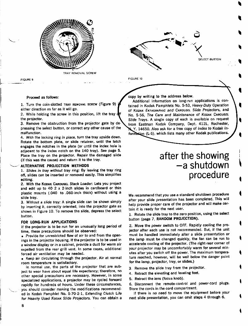
Proceed as follows:
TRAY REMOVAL SCREW
1. Turn the coin-slotted TRAY REMOVAL SCREW (Figure 9)either direction as far as it will go.2. While holding the screw in this position, lift the traythe projector.3. Remove the obstruction from the projector gate by de-pressing the select button, or correct any other cause of themalfunction .4. With the locking ring in place, turn the tray upside down .Rotate the bottom plate, or slide retainer, until the latchengages the notches in the plate (or until the index hole isadjacent to the index notch on the 140 tray) . See page 5.Place the tray on the projector. Repair the damaged slide(if this was the cause) and return it to the tray .
---' ALTERNATIVE PROJECTION METHODS1. Slides in tray without tray ring: By leaving the tray ringoff, slides can be inserted or removed easily . This simplifiesediting.2. With the KODAK CAROUSEL Stack Loader: Lets you projectand edit up to 40 2 x 2-inch slides in cardboard or thinplastic mounts (.040 to .060-inch thick) without using aslide tray .3 . Without a slide tray: A single slide can be shown simplyby inserting it, correctly oriented, into the projector gate asshown in Figure 10 . To remove the slide, depress the selectbutton .
FOR LONG-RUN APPLICATIONSIf the projector is to be run for an unusually long period oftime, these precautions should be observed :. Provide for unrestricted flow of air to and from the open-ings in the projector housing. If the projector is to be used ina window display or in a cabinet, provide a duct for warm airexpelled from the rear grill vent . In some cases, additionalforced air ventilation may be needed .. Keep air circulating through the projector. Air at normalroom temperature is satisfactory.
In normal use, the parts of the projector that are sub-ject to wear have about equal life expectancy ; therefore, noother special precautions are necessary. However, in somespecialized applications, a projector may be cycled forwardrapidly for hundreds of hours. Under these circumstances,you should consider making the modifications recommend-ed in Kodak Pamphlet No . S-70-2-1, Extending Clutch Lifefor Heavily Used KODAK Slide Projectors . You can obtain a
FIGURE 10
0
SELECT BUTTON
copy by writing to the address below.Additional information on long-run applications is con-
tained in Kodak Pamphlets No. S-53, Heavy-Duty Operationof KODAK EKTAGRAPHIC and CAROUSEL Slide Projectors, andNo. S-56, The Care and Maintenance of KODAK CAROUSEL
Slide Trays. A single copy of each is available on requestfrom Eastman Kodak Company, Dept . 412L, Rochester,
Y. 14650. Also ask for a free copy of Index to Kodak In-(L-5), which lists many other Kodak publications./
'
We recommend that you use a standard shutdown procedureafter your slide presentation has been completed. This willhelp provide proper care of the projector and will make cer-tain it is ready for the next user .1 . Rotate the slide tray to the zero position, using the selectbutton (page 7, RANDOM PROJECTION).
2. Move the power switch to OFF. Rapidly cooling the pro-jector after each use is not recommended. But, if the unitmust be handled immediately after a slide presentation orthe lamp must be changed quickly, the fan can be run toaccelerate cooling of the projector. (The right-rear corner ofyour projector may be uncomfortably warm for several min-utes after you switch off the power. The maximum tempera-ture reached, however, will be well below the danger pointfor the lamp, projector, tray, or slides .)
after the showing-a shutdown
procedure11
3 . Remove the slide tray from the projector.
4. Retract the elevating and leveling feet .
5. Retract the lens (focus knob).
6. Disconnect the remote-control and power-cord plugs.Store the cords in the cord compartment.
If there is no need to move the equipment before yournext slide presentation, you can omit steps 4 through 6.
7ach of the items described below is a useful accessory for the.ODAK EKTAGRAPHIC Slide Projector, Model AF-2 .
KODAK CAROUSELUniversal Slide Tray
KODAK CAROUSEL 80Slide Tray
KODAK CAROUSEL 140AM Slide Tray
Additional slide trays, supplied in attractive bookshelf-type stor-age boxes . Each box contains an identification card and traysticker. Use the CAROUSEL Universal Slide Tray for all slides, in-cluding glass-mounted slides up to 1/8 inch thick ; use theCAROUSEL 80 Slide Tray for slides mounted in cardboard or thinglass (up to 1/10 inch thick). For 140-slide capacity of slidesin cardboard or thin plastic mounts up to 1/16 inch thick, usethe CAROUSEL 140 Slide Tray.
KODAK CAROUSELProjector Case,Model B
-J Accommodates projector, one slide tray, extra lenses, cords,and spare lamp . Made of gray, heavy-duty simulated leather.Provides complete protection plus convenience and attractiveappearance during transportation and storage . (Will hold theKODAK EKTAGRAPHIC Slide Projector, Model AF-2, with 7-inch orzoom lens in place if the projector is inserted on its side .)
10
KODAK Carrying Casefor KODAKCAROUSELSlide Trays
Has two compartments so that three slide trays can be carriedor one or two trays plus extension cords, lenses, and otherequipment.
KODAKAV CompartmentCase
A convenient, rugged case of vulcanized fiber. Will accommo-date the KODAK EKTAGRAPHIC Slide Projector, Model AF-2, with7-inch or zoom lens in place . Also will hold one slide tray, extralenses, cords, and spare projection lamp .
Several KODAK Projection Lensesjector. See table on page 3 .
KODAKProjection Lenses
KODAK CAROUSELDissolve Control, Model 2
KODAK CAROUSELSound Synchronizer, Model 2
auxiliaryequipment
Extends the range of the 12-foot remote control cord so thatyou can operate the projector from a location near the screen .Several extension cords can be added to accommodate anyreasonable projection distance .
Controls two Model AF-2 projectors for slide shows in whichone image "dissolves" into the next while screen illuminationremains virtually constant . The unit contains a timer for con-tinuous automatic operation, or it can be controlled by theremote control cord of one of the projectors . Can also be con-trolled by the KODAK CAROUSEL Sound Synchronizer, Model 2 .Ideal for sales presentations or more sophisticated slideshowings.
This unit permits a stereo record/playback tape recorder, thatis equipped with an external speaker jack, to be used as a pro-grammer with your projector. In operation, one of the tapetracks is used for slide-change signals while all other soundis recorded on the other channel . Can also control two projec-tors through a KODAK CAROUSEL Dissolve Control.
1
are available for your pro-
KODAK RemoteExtension 1Cord, 25-Foot
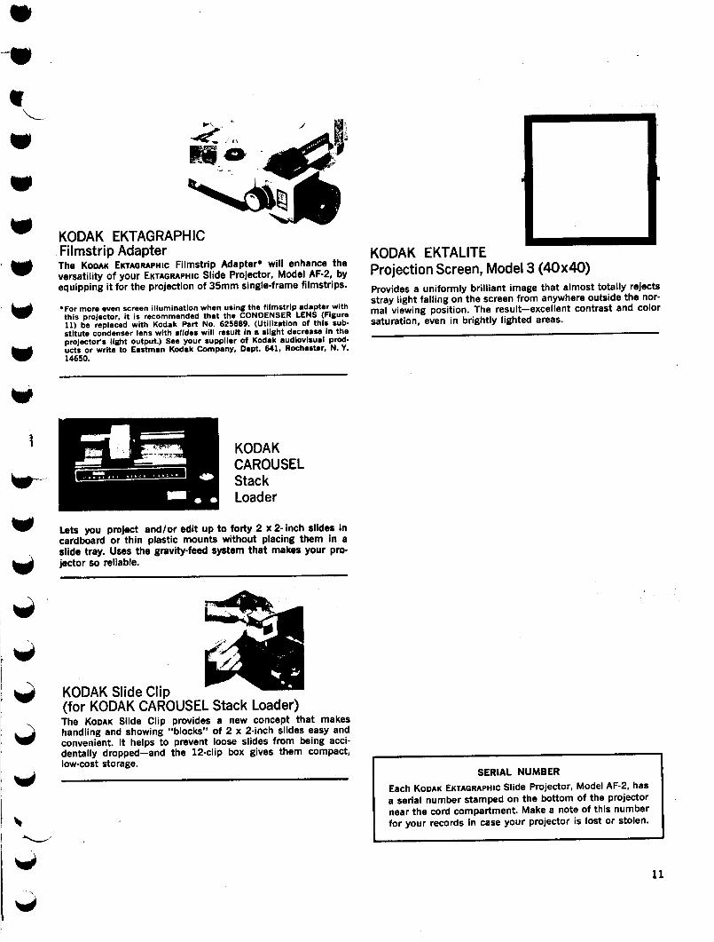
KODAK EKTAGRAPHICFilmstrip AdapterThe KODAK EKTAGRAPHIC Filmstrip Adapter* will enhance theversatility of your EKTAGRAPHIC Slide Projector, Model AF-2, byequipping it for the projection of 35mm single-frame filmstrips.
-For more even screen illumination when using the filmstrip adapter withthis projector, it is recommended that the CONDENSER LENS (Figure11) be replaced with Kodak Part No . 625889. (Utilization of this sub-stitute condenser lens with slides will result In a slight decrease in theprojector's light output .) See your supplier of Kodak audiovisual prod-ucts or write to Eastman Kodak Company, Dept. 641, Rochester, N . Y.14650.
KODAK Slide Clip
KODAKCAROUSELStackLoader
Lets you project and/or edit up to forty 2 x 2- inch slides incardboard or thin plastic mounts without placing them in aslide tray. Uses the gravity-feed system that makes your pro-jector so reliable .
(for KODAK CAROUSEL Stack Loader)The KODAK Slide Clip provides a new concept that makeshandling and showing "blocks" of 2 x 2-inch slides easy andconvenient. It helps to prevent loose slides from being acci-dentally dropped-and the 12-clip box gives them compact,low-cost storage .
KODAK EKTALITEProjection Screen, Model 3 (40x40)Provides a uniformly brilliant image that almost totally rejectsstray light falling on the screen from anywhere outside the nor-mal viewing position . The result-excellent contrast and colorsaturation, even in brightly lighted areas .
SERIAL NUMBER
Each KODAK EKTAGRAPHIC Slide Projector, Model AF-2, hasa serial number stamped on the bottom of the projectornear the cord compartment . Make a note of this numberfor your records in case your projector is lost or stolen .
Pub. Pt . No . 634464
warrantyKODAK EKTAGRAPHIC Slide Projector, Model AF-2
Carefully follow all the instructions in this manual to get the best results and toprevent damage to your projector .
Your projector will be repaired at no charge within one year after purchase,except for worn-out projection lamps and damage caused by misuse or circum-stances beyond Kodak's control . This warranty applies only to the projector,and Kodak cannot be responsible for other losses or damages of any kindresulting from projector failure .
Except as mentioned above, no other warranty, express or implied, applies tothis slide projector .
For service during or after the warranty period, you may take your projector toa Kodak Consumer Center (located in many U .S . cities) . Please consult yourlocal telephone directory under Photographic Equipment and Supplies for thelocations of these centers. You- may also return the projector directly or througha dealer in Kodak audiovisual products to one of the following Kodak EquipmentService Centers . To help us get the projector back to you promptly, pleaseenclose a note giving the details of the projector malfunction and date ofpurchase .
Eastman Kodak Company
Eastman Kodak Company
Central Equipment Service Center
Regional Equipment Service Center
800 Lee Road
1334 York Ave.Rochester, N. Y. 14650
NewYork, N . Y. 10021
Eastman Kodak Company
Eastman Kodak CompanyRegional Equipment Service Center
Regional Equipment Service Center5315 Peachtree Industrial Blvd .
1901 West 22nd St.Chamblee, Ga. 30341
Oak Brook, III . 60521
Eastman Kodak Company
Eastman Kodak CompanyRegional Equipment Service Center
Regional Equipment Service Center2800 Forest La .
9100 Alcosta Blvd .Dallas, Tex . 75234
San Ramon, Calif . 94583
Eastman Kodak Company
Eastman Kodak CompanyRegional Equipment Service Center
Regional Equipment Service Center12100 Rivera Rd .
1122 Mapunapuna St .Whittler, Calif. 90606
Honolulu, Hawaii 96819
Service is also available through dealers selling Kodak audiovisual products .Refer to the yellow pages of your telephone directory under Audiovisual Equip-ment and Supplies.
Kodak. Ektagraphie, Carousel, Ektanar,Ektanon, and Ektalite are trademarks.
MOTION PICTURE AND AUDIOVISUAL MARKETS DIVISIONRochester, N. Y. 14650
10-74-AB-Reprint
Basic Operating InstructionsKODAK EKTAGRAPH I C Slide Projector,
Model AF-2
(DPLUG IT INOpen door on bottomof projector and withdrawfull length of powercord
'
*Position tray with zero (0) at gate index.
CONNECT REMOTECONTROL(orientationdot facing up)
0INSTALL TRAY'`
FOCUSthe image onthe screen(or use focusknob)
TURN IT ONMove switch toLOW or HIGH(Be sure timeris set at M)
Emergency
Elevating WheelTray Removal
(under handle)Screw
PRESSto projectfirst slide(or use for-ward button)
ReverseButton
(See other side)
Pub. Pt . No . 834485
ELEVATING WHEEL. To raise or lower the image on the screen, turn the elevatingwheel on the front of the projector.
. LEVELING-FOOT WHEEL. To raise or lower the left side of the image on the screen,turn the leveling-foot wheel.
REMOTE CONTROL (Timer set at M) . To project the slide with the next higher identifi-cation number, momentarily depress the forward button ; to rotate the tray one slidespace in the reverse (clockwise) direction, depress and release the reverse button .(Press the reverse button firmly; if this button is pressed too lightly, the tray may rotatein a forward direction.) To focus the image on the screen, use the focus lever.
These functions can also be accomplished by operating the forward button, thereverse button, and the focus knob on the projector body .
RANDOM PROJECTION (Timer set at M). To project a slide out of sequence :1 . Firmly depress the select button and hold it down .2. Rotate the slide tray until the slide you want to project is opposite the gate
index on the projector.
3. Release the select button . The selected slide will be immediately projected.AUTOMATIC TIMER. For automatic advance of slides at intervals of 5, 8, or 15 seconds,set the timer at "5", "8", or "15" respectively .
SLIDE-TRAY REMOVAL. If the zero position on the tray is opposite the gate index,simply lift off the tray . Otherwise:
1 . With the projector turned on, depress the select button firmly and hold it down .2. Rotate the slide tray-in either direction-until the zero position is opposite the
gate index.
3. Release the select button and then lift off the tray .
EMERGENCY SLIDE-TRAY REMOVAL. If for any reason it becomes necessary to removethe tray without returning it to the zero position, use this procedure:
1 . Turn the coin-slotted tray removal screw in either direction as far as it will go .2. Hold the screw in this position and lift off the tray .
3. Turn the tray upside down and rotate the bottom plate until it locks.
PROJECTION LAMP REPLACEMENT. If the lamp burns out during a showing:1 . Allow the fan to run to cool the lamp and lamp compartment.2. Remove the slide tray .
3. Move the switch to OFF.
4. Disconnect the power cord .
5. Turn the projector upside down .
6. Open the lamp door by turning the coin-slotted screw counterclockwise .7. Release the lamp ejector lever from the notch in which it is secured. Lift the
lever to eject the lamp . Withdraw the lamp.
8. Place a new lamp (ANSI Code ELH) in the socket with the two pins on its basefitting the two slots in the socket. (Code ENH lamp can be used for extended lamplife with less output; ENG lamp for more brightness, but shorter life .)
9. Return the ejector lever to its original position and make sure it is latched. Thelever will locate the lamp correctly for operation.
10 . Close and fasten the lamp door .
,
For more detailed information, refer to the instruction manual .Kodak and Ektagraphic are trademarks.
Motion Picture and Audiovisual Markets DivisionEASTMAN KODAK COMPANY " ROCHESTER, N.Y. 14650
8-74-BX-Reprint
012''03/1396 22 :55 2134620623
ANGSTROM STAGE LIGHTING,INC.
FAX TRANSMITTAL
DELIVER TO:FAX NUMBER:
505-473-0614NAME: Bruce Hamilton
COMPANY :DATE:
Thursday, January
TIME:
9:50 AMSENT FROM:
Juan
ANGSTROM STAGE LTNG
4, 1996
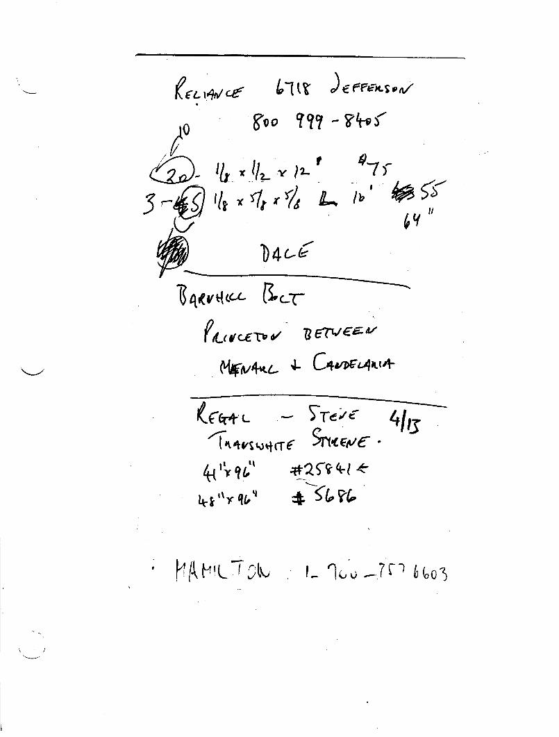
Bruce .,Here are the specifications on the LD-360M Dimmer packs.The sale price for the LD-360M is $595.00 plus tax.Delivery is about one week. Please, call me if you have anyquestions .Thanks
837 N. Cahuenga Blvd . Hollywood, CA 90038 (213) 462-5923 FAX (213) 462-0623
01103x/1996 22:55 2134620623
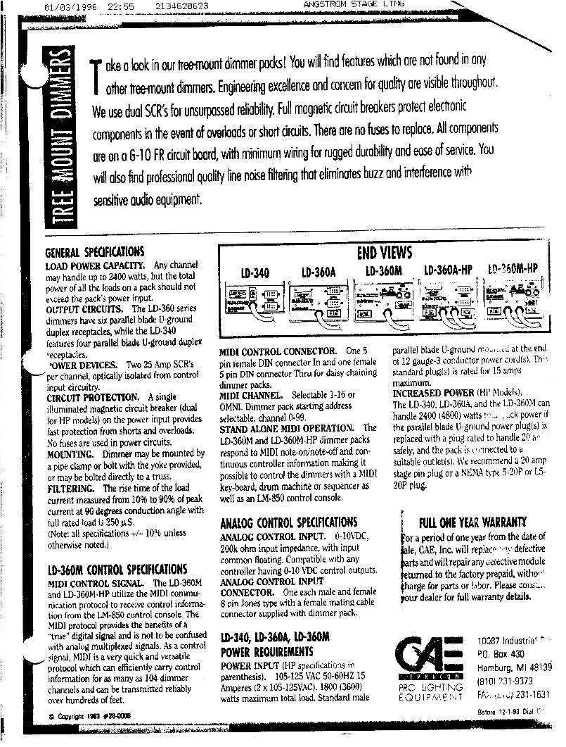
Toke a look in our tree-mount dimmer packs! You will find features which are not found in any
other tree~rlaunt dimmers. Engineering excellence and concern for quality are visible throughout .
We use dual SCR's for unsurpassed reliability. Full magnetic circuit breakers protect electronic
components in the event of overloads or short circuits. There are no fuses to replace. AI components
are on a G-1 Q FR circuit board, with minimum wiring for rugged durability and ease of service. You
will also find professional quality line noise filtering that eliminates buzz and interference with
sensitive audio equipment,
GENERAL SPECIFICATIONS
LOAD POWER CAPACITY. Any channelmay handle up to 2400 watts, but the totalpower of all the loads on a pack should notexceed the pack's power input.OUTPUT CIRCUITS.
The LD-360 seriesdimmers have six parallel blade U-groundduplex receptacles, while the LD-340features four parallel blade U-ground duplex"eceptacles.'OWER DEVICES. Two 25 Amp SCR's
per channel, optically isolated from controlinput circuitry .CIRCUIT PROTECTION . Asingleilluminated magnetic circuit breaker (dualfor HP models) on the power input providesfast protection from shorts and overloads.
No fuses are used in power circuits .MOUNTING. Dimmer may be mounted by
a pipe clamp or bolt with the yoke provided,or may be bolted directly to a truss .FILTERING.
The rise time of the loadcurrent measured from 10% to 9096 of peakcurrent at 90 degrees conduction angle withfull rated load is 250uS .(Note: all specifications +/-101,16 unlessotherwise noted.)
LD-360M CONTROL SPECIFICATIONS
MIDI CONTROL SIGNAL. The LD-360Mand LD-360M-HP utilize the MIDI commu-nication protocol to receive control informa-tion from the 1..M-850 control console. TheMIDI protocol provides the benefits ofa"true" digital signal and is not to be confusedwith analog multiplexed signals. As a controlsignal, MIDI is a very quick and versatileprotocol which can efficiently carry controlinformation for as many as 104 dimmerchannels and can be transmitted reliablyover hundreds of feet.
0 Copyright 1993 *xe-0008
ANGSTROM STAGE L_T Nia
LD"340, LD"360A, LD-360M
i ,o
v ,i
v ,n ~
,f
_
a -
s -
MIDI CONTROLCONNECTOR. One 5pin female DIN connector In and one female
5 pin DIN connector Thru for daisy chainingdimmer packs.MIDI CHANNEL.
respond to MIDI note-oninote-off and con-tinuous controller information making it
possible to control the dimmers with a MIDIkey-board, drum machine or sequencer as
well as an LM-850 control console.
ANALOG CONTROL SPECIFICATIONS
ANALOG CONTROL INPUT. 0-10%T)C,200k ohm input impedance, with inputcommon floating . Compatible with anycontroller having 0-10 VDC control outputs.ANALOG CONTROL INPUTCONNECTOR.
One each male and female8 pin Jones ttiroe with a female mating cableconnector supplied with dimmer pack .
POWER REQUIREMENTS
POWER INPUT (I-JP Speciticati(ns inparenthesis) .
105-125 VAC 50-64HZ 15Amperes (2 x 10⁵-125V4C) . 1800 (3600)watts maximum total load . Standard male
parallel blade U-ground m'?,o :-Lu at the endof 12 gauge-3 conductor power cord(s) . Th ;standard plug(s) is rated for 1.5 ampsmaximum.INCREASED POWER (Hi' Mod0s) .The LD-340, LD-360A, and the LD-360I canhandle 2400 (4800) watts t- . . .. , :;ck power if
the parallel blade 1.1-ground power plug(s) is
replaced with a plug rated to handle 20 a
safely, and the pack is crnnected to asuitable outlet(s) . We recommend a 20 amp
stage pin plug or a NI;aA44 type , . .24P or 1,5-20P plug.
I FULL ONE YEAR WARRANTY
or a period of one year from the date of
e, CAE, Inc. will replaco ., -1N" defective
itsand will repairany aefective moduleeturrled to the factory prepaid, witho! , `;~harge for parts or labor. Please cons ; .your dealer for full warranty details .
rr 10087lodustrialRIRI11
?0. Box 430Hamburg, MI 4813918101 731-
PR0 li , HTiNG9373
E(DUIFA', 231-1631
_'E V R ! C tl H
Before 12-1-93 Dial f.
FROM :CAE INC .
TO :
5054730614
APR 4, 1994
1:10PM P.01
TAX Transmission10087 Industrial Dr., P.0 . Box 430, 11Amburg,1;v1148139 USA
Auipment, LillliteG Owsaneck Lamps bt . Accessories and ISYS'm Lighting
Messtigc :
~ ryr>
FROM:CAE INC .
Tate a look in our tree-mount dimmer packs! You will find features which are not found in any
other tree-mount dimmers. Engineering excellence and. concern for quality are visible throughout.
We use dual SCR's for unsurpassed reliability. Full magnetic circuit breakers protect electronic
components in the event of overloads or short circuits. There are no fuses to replace. All components
are on a G-10 FR circuit board, with minimum wiring for rugged durability and ease of service. You
will also find professional quality line noise filtering that eliminates buzz and interference with
sensitive audio equipment.
c
GENERAL SPECIFICATIONS
LOAD POWER CAPACITY. Any channelmay handle up to 2400 watts, but the totalpower of all the loads on a pack should notexceed the pack's power input .OUTPUT CIRCUITS. The LD-360 seriesdimmers have six parallel blade U-groundduplex receptacles, while the LD-340features four parallel blade 13-ground duplexreceptacles .')WER DEVICES.
Two25 Amp SCR'sr channel, optically isolated from control
input circuitry.CIRCUIT PROTECTION. A singleilluminated magnetic circuit breaker (dualfor HP models) on the power input providesfast protection from shorts and overloads .No fuses are used in power circuits .MOUNTING.
Dimmer may be mounted bya pipe clamp or bolt with the yoke provided,or may be bolted directly to a truss .FILTERING.
The rise time of the loadcurrent measured from 10% to 90% of peakcurrent at 90 degrees conduction angle withfull rated load is 250 gS .(Note : all specifications +/-10% unlessotherwise noted.)
LD-360M CONTROL SPECIFICATIONS
MIDI CONTROL SIGNAL. The LD-360Mand LD-360M-11P utilize the MIDI commu-nication protocol to receive control informa-tion from the IN-850 control console . TheMIDI protocol provides the benefits of a"true" digital signal and is not to be confused
'h analog multiplexed signals. As a control1al, MIDI is a very quick and versatile
fotocol which can efficiently carry controlinformation for as many as 104 dimmerchannels and can be transmitted reliablyover hundreds of feet.
TO :
5054730614
APR 4, 1994
LD-340
`,,END VIEWS
LD-360A
'' LD-360M
LD-360A-HP LD-360M-HP
MIDI CONTROL CONNECTOO. One 5pin female DIN connector In and one female5 pin DIN connector Thru for daisy chainingdimmer packs.MIDI CHANNEL.
Selectable 1-16 orOMNI. Dimmer pack starting addressselectable, channel 0-99 .STAND ALONE MIDI OPERATION . TheLD-360M and LD-364M-HP dinimer packsrespond to MIDI note-on/note-off and con-tinuous controller information making itpossible to control the dimmers with a MIDIkey-board, drum machine or sequencer aswell as an LM-850 control console.
ANALOG CONTROL SPECIFICATIONS
ANALOG CONTROL INPUT. !0-l0VDC,200k ohm input impedance, with inputcommon floating. Compatible With anycontroller having 0-10 VDC control outputs .ANALOG CONTROL INPUTCONNECTOR.
One each ma1G and female8 pin Jones type with a female mating cableconnector supplied with dimmer pack.
LD-340, LD-360A, LD-360M
POWER REQUIREMENTSPOWER INPUT (LIP specifications inparenthesis) .
105-125 VAC 50-60HZ 15Amperes (2 x 10⁵-125VAC).1800 (3600)watts maximum total load . Standard male
parallel blade U-ground mounted at the endof 12 gauge-3 conductor power cord(s) . Thisstandard plug(s) is rated for 15 ampsmaximum .INCREASED POWER (HP Models) .The LD-340, LD-360A, and the LD-360M canhandle 2400 (4800) watts total pack power ifthe parallel blade i1-ground power plug(s) isreplaced with a plug rated to handle 20 ampssafely, and the pack is connected to asuitable outlet(s) . We recommend a 20 ampstage pin plug or a NFMA type 5-20P or L5-20P plug.
FULL ONE YEAR WARRANTYFor a period of one year from the date ofsale, CAE, Inc. will replace WV defedive .partsand will repairanydefe ti mo le'returned to the factory prepald wlthoiitcharge for parts or labor, Please Consultyour dealer for full warranty det (ls;_
ttretcort
1:11PM P.02
S
10087 Industrial Drive
P.0, Box 430
Hamburg, MI 48134
PRO LIGHTING
(313) 231-9373
EQUIPMENT FAX (313) 2311631
e~.lanr ~ {LINE
. .
r ;-7 311 L311
FROM "CAE INC .
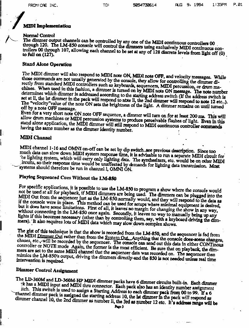
H=IImplementation
TO :
5054730614
AUG 9, 1994
1 " 35PM P.01
Normal Control--
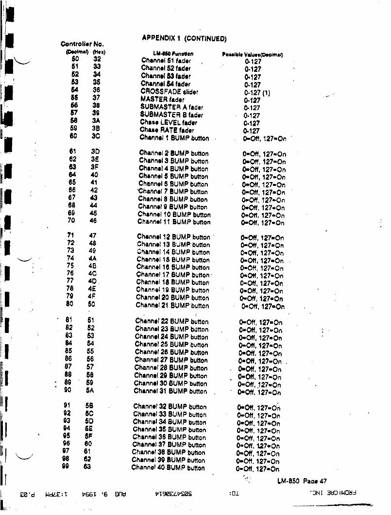
The dimmer output channels can be controlled by any one of the MIDI continuous controllers 00through 120. The LM-850 console will control the dimmers using exclusively MIDI continuous con-trollers 00 through 107, allowing each channel to be set at any of 128 discrete levels from light off (0)to full on (127).
Stand Alone Operation
MIDI Channel
The MIDI dimmer will also respond to MIDI note ON, MIDI note OFF, and velocity messages. Whilethose commands arc not usually generated by the console, they allow for controlling the dimmer di-rectly from standard MIDI controllers such as keyboards, sequencers, MIDI percussion, or drum ma-chines . When used in this fashion, a dimmer is turned on by MIDI note ON messyge. The note numberdetermines which dimmer is addressed according to the
address switch (If the address switch isset at 11, the lst dimmer in thepack will respond to nbte~nddimmer will respond to note 12 ere . .) .The °velocity"value of the note ON sets the brightness of the light. A dimmer remains on until turnedoff by a note OFF message .Even for a very short note ON note OFF sequence, adimmer will turn on for at least 200 ms. This willallow drum machines or MIDI percussion systems to produce perceivable flashes of light. Even in thisstand alone application, the MIDI dimmer will still respond to MIDI continuous controller commandshaving the same number as the dimmer identity number.
.
MIDI channel 1-16 and OMNI on-off can be set by dip switch-seeprevious description. Since too .much data can slow down MMI system response time, it is advisable to run a separate MIDI circuit forhe lighting system, which will early only lighting data . no synthesizers, etc. would be on otherMIDI,ircutts, so their response time would be unaffecte11,y demands for lighting data transrtission Most.'-"sYstems should therefore be run in channel 1, OMNI ON.Playing Sequenced Cues Without the LM.8s0For specific applications, it is possible to use the LM-850 to program a show where the console wouldnot be used at all for playback, if M11)I dimmers are being used . The dimmers can be plugged
intotheMIDI Out from the sequener just as the LM-850-normally would, and they will respond to the data asif the console were in place . This method can be used for setups where minimal equipment is desired,but it does have some limitations. First of all, it leaves no margin for changing the show in any way,without connecting in the LM-850 once again . Secondly, it leaves no way to manually being up anylights if this becomes n
(other than by controlling thorn, say, with a keyboard driving the dim-mers). :It also requires lots of
I data whichmldlhay sowown oompcx sows.The gist of this technique is that the show is raoordcd from the LM-850 and the sequcneer i
fr,sTeaomthe MIDI Fimmer Opt rather than from the System
. ,,A~+ythin8 that the console does-scene changes,chases, etc.,-will be recorded by the seguencer, The console can send out this data in either CONTinouscontroller or NOTE mode Again, the former is the most efficient . Be sure that on playback, the dim-mers are set to the same MMI channel that the sequener data was reeonied osoquencer theninterventionmimics the
isLM-850's
required .output, driving the dimmers directly
n. The-and the .850 is not needed unless real time.
Dimmer Control Assignment
The LD-360M and LD-360M-HP MmI dimmer packs have 6 dimmer circuits built-in. Each dimmer~k has a MIDI input and MMI thru connector. Each pack also has an identity number assignmentitch. This switch is used to assign a Starting Address to each dimmeryack from 00 to 99. If a 6channel dimmer pack is assigned the starting address 10, the tst dimmerm the pack will respond asdimmer channel 10, the 2nd dunmer as number 11, the 3rd as number 12 etc . Its addrm range will bePw 3
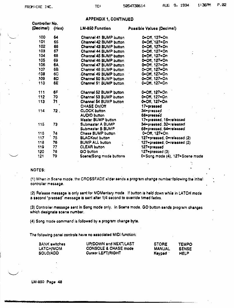
(4) Song mode command is followed by a program change byte .
The following panel controls have no associated MIDI function :
UP/DOWN and NEXT/LASTCONSOLE & CHASE modeCursor LEFTIRIGHT
AUG 9, 1994
1:36PM P.02
(1) When in Scene mode, the CROSSFADE slider sends a program change number following the initialcontroller message .
(2) Release message is only sent for MOMentary mode. If button is held down while in LATCH mode.a second pressed' message is sent after 1/4 second to override timed fades,
(3) Controller message sent in Song mode only. In Scene mode, 00 button sends program changeswhich designate scene number .
STORE TEMPOMANUAL SENSEKeypad °
HELP
(Decimal) (Hex) LM-850 Function Possible Values (Decimal)
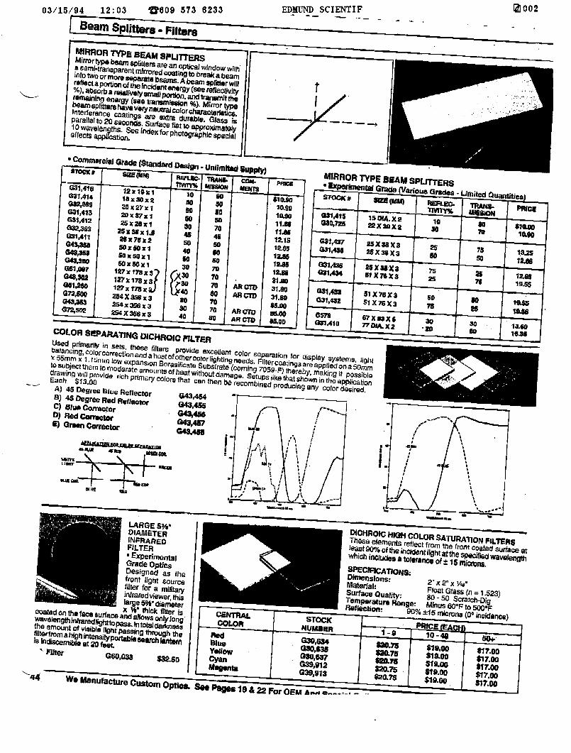
.Interierance coatings are extra durable. Glass isParallel to 20 seconds. Surface flat to approximately10wavelen ths. %eIndex forphotographicspecialellects aPPICtion.
e mesa Fillers prov;cte excellent Color e0paration for gisptay 3ystelightseism;ng,cu5rcorrectionandahosthostOfothercolorlighting needu, r-tltercoetingsanFappgedShx55mm x 1 .f m;n
lowexpansion Sorasil;cate Subtt ( onaDmsraecoming7059-F) thereby, making it possible
to subject thorn to moderate. amountsamounts ofbeatheatWithoutwithoutdamage. Setups like that shown an the applicationA) 4S
drawing v130
provide rich primary colorEach
Will
s that can then be recombinedlike
soy colordesired,Degree Blue ReflectorRl AC n
0,43agree Red Reflector
C) Blue CorrectorRedCorrector
E) Qreon Corrector
LARGE 5%"DIAMETERINFRAREDFILTER- ExperimentalGrade opticsDesigned as thefront light sourcefilter for a militaryinfrared viewer, thislarge5W diameter
ousted on theface surfac
xWthick filter iseand allows onlylongwavelengthinfraredrighttopass.In totaldarknessthe amount of visible light passing through thefaterfromahigh intensityportable,.arch lagem;s indiscernible at 20 feet
f)ICNROIC HIGH COLORSATURATIONFILTERSThese elements reflect from the front coated surtaceleast9096 ofthe incident light3tthe sp®c;redwavelengthwhich includes a tolerance of ± 15 microns.SPECIFICATIONS,Dimensions : 2' x 2° X Via"Material.-Surface Quality:
MIRROR TYPE BEAM SPUTTERSAAirrortypbeam Spffttn ers are an optical windowaSemi-tt n9par~ent mirrored
with'coating to breakabeamInto two ormore separate beasts. Abeam spfitter will
reflect
aportion oftheincident energy {see refleotivl)absorba relatively small portion. and transmit theremaining energy (see transmission %) . Mirror typebeam sputtershaveveryneutralcolorcharacterlst;c8.interference coatings are GXtra dumble. Glass ;sparallel to 2Q seconds. Surface flat apapproximately10wavelAngths_ Sec Indexforphotographlespecialolfects appiction.
LARGE 53A "DIAMETERINFRAREDFILTER" ExperimentalGrade OpticsDesigned as thefront light sourcefilter for a militaryinfrared viewer, thislarge 5%"diameterx 1Y thick filter isCoated on the face surface and allows onlylongwavelengthinkaredlghtto .Intotaldarknessthe amount of visible light passing through theflterfromahigh intensityportable aedrt h nis Indiscernible at 20 feet,
Filter G60,038 $3250
$609 573 6233
r
Red13lueYellowCyanate
All=AR=
Used primarily in sets . thesefillers provide excellent color separation for gisplay 3ya~tenl9 . lightbalancing,colorcorrectionandahcatofother
colorlighting needv. Filter coatings areappliedon aSorrimx 55mm x 1 .15mrn low expansion Snrasilicate Substrate (coming 7059-F) thereby, making it possibletosubject thorn to moderate amounts ofheat without damage . Setups like thatshown in the applicationdrawing will provide rich primary colors that can then be recombined ke
that
any color pplicatiEach 313.00A) 415 Degree glue Reflector
13434,5413) 45 Degree Red Reflector
00,455C) Blue CorrectorD) RedCorrectp.E) Green Corrector
MIRROR TYPEEBEAM SPUTTERS!!~r~tOl G (various Grades - Lrmited Quantities)STOCK*
sne......
-
30-20
DIOHROIC HIGH COLOR SATURATION FILTERSThese elements reflect from the front coated surface at10615t 90%ofthe incldentl4htatthe specifiedwavelertgdtwhich inpltldes a tolerance of±15 mi0Mns.SPECIFICATIONS:Dimensions: 2° x 2� x , eMaterial :