124
BROWARD COMMUNITY COLLEGE DESIGN & CONSTRUCTION CRITERIA & STANDARDS MAY 30, 2003

BROWARD COMMUNITY COLLEGE
DESIGN & CONSTRUCTION
CRITERIA & STANDARDS
MAY 30, 2003
Broward Community College Design & Construction Criteria Standards
Date: 05/30/2003
Table of Contents 00010 - Page 1 of 1
SECTION 00010
BROWARD COMMUNITY COLLEGE DESIGN & CONSTRUCTION CRITERIA STANDARDS
TABLE OF CONTENTS DIVISION/SECTION TITLE PAGE NO. INTRODUCTORY INFORMATION 1 - 5 Section 00001 - Title Page 00010 - Table of Contents 00200 - Instructions to Consultants and Contractors DIVISION 1 - GENERAL REQUIREMENTS 1 - 21 Section 01200 - Price and Payment Procedures 1 - 3 01300 - Administrative Requirements 1 - 5 01355 - CADD Requirements 1 - 1 01400 - Quality Requirements 1 - 2 01500 - Temporary Facilities and Controls 1 - 3 01600 - Product Requirements 1 - 1 01700 - Execution Requirements 1 - 3 01800 - Facility Operation 1 - 2 01935 - Hazardous Materials Abatement, Removal and Disposal 1 - 1 DIVISION 2 - SITE CONSTRUCTION 1 - 6 Section 02210 - Subsurface Investigation 02360 - Soil Treatment 02500 - Utility Services 02580 - Site Lighting 02585 - Manholes and Hand-Holes 02810 - Irrigation System 02900 - Planting DIVISION 3 - CONCRETE RESERVED DIVISION 4 - MASONRY 1 - 1 Section 04050 - Basic Masonry Materials and Methods DIVISION 5 - METALS 1 - 2 Section 05520 - Handrails and Railings DIVISION 6 - WOOD AND PLASTICS 1 - 2

Broward Community College Design & Construction Criteria Standards
Date: 05/30/2003
Table of Contents 00010 - Page 2 of 2
Section 06190 - Wood Backing Panels for Utility Services 06400 - Architectural Woodwork DIVISION 7 - THERMAL AND MOISTURE PROTECTION 1 - 3 Section 07510 - Modified Bituminous Membrane Roofing 07800 - Fire and Smoke Protection 07920 - Joint Sealants DIVISION 8 - DOORS AND WINDOWS 1 - 5 Section 08050 - Basic Door and Window Materials and Methods 08710 - Door Hardware 08715 - Hardware Keying DIVISION 9 - FINISHES 1 - 15 Section 09300 - Tile 1 - 1 09500 - Ceilings 1 - 1 09600 - Flooring 1 - 8 09900 - Paints and Coatings 1 - 5 DIVISION 10 - SPECIALTIES 1 - 4 Section 10150 - Toilet Compartments 10260 - Wall and Corner Guards 10270 - Access Flooring 10400 - Identification Devices 10520 - Fire Protection Specialties 10600 - Partitions 10810 - Toilet Accessories DIVISION 11 - EQUIPMENT 1 - 1 Section 11135 - Audio/Visual Screens 11160 - Loading Dock Equipment DIVISION 12 - FURNISHINGS 1 - 12 Section 12490 - Window Treatments 12740 - Office Work Stations (including schematic layouts) DIVISION 13 - SPECIAL CONSTRUCTION 1 - 2 Section 13700 - Security Systems DIVISION 14 - CONVEYING SYSTEMS 1 - 1 Section 14200 - Elevators
Broward Community College Design & Construction Criteria Standards
Date: 05/30/2003
Table of Contents 00010 - Page 3 of 3
DIVISION 15 - MECHANICAL 1 - 31 Section 15000 - Mechanical Design Requirements 1 - 3 15050 - Basic Mechanical Materials and Methods 1 - 4 15100 - Building Services Piping 1 - 3 15300 - Fire Protection 1 - 1 15410 - Plumbing Fixtures and Equipment 1 - 2 15600 - Refrigeration (including schematics) 1 - 14 15700 - HVAC and Air Distribution 1 - 3 15910 - Direct Digital Controls 1 - 1 DIVISION 16 - ELECTRICAL 1 - 28 16000 - Electrical Design Requirements 1 - 6 16050 - Basic Electrical Materials and Methods 1 - 4 16100 - Wiring Methods 1 - 5 16200 - Electrical Power 1 - 4 16400 - Power Distribution 1 - 1 16500 - Lighting 1 - 3 16600 - Lightning Protection 1 - 1 16900 - Fire Alarm System 1 - 4
END OF SECTION 00010
Broward Community College Design & Construction Criteria Standards
Date: 05/30/03
Introductory Information Page 1 of 1
INTRODUCTORY
INFORMATION

Broward Community College Design & Construction Criteria Standards
Date: 05/30/03
Instructions To Consultants And Contractors 00200 - Page 1 of 1
INSTRUCTIONS TO CONSULTANTS AND CONTRACTORS SECTION 00200 DESIGN & CONSTRUCTION CRITERIA STANDARDS These criteria standards have been assembled to provide design consultants (Architect/Engineers) and construction and/or installation Contractors with certain requirements that are to be incorporated into the design and construction of capital projects for Broward Community College (College). The purpose of these criteria standards is threefold:
• To provide for uniformity in the College's building systems in order to facilitate stocking of repair parts and the timely response to maintenance problems
• To effect reliable, cost-effective building systems that will maintain maintenance costs at reasonable levels, and interruptions to the College's academic operations
• To reinforce compliance with applicable laws, Codes, and regulations With few exceptions, these criteria standards are not proprietary. Where criteria standards are proprietary, it is because the College's Board of Trustees has approved such limits on competition as being in the long-term best interest of the College as permitted under Florida Statutes. THE CRITERIA STANDARDS INCLUDED IN THIS DOCUMENT ARE MANDATORY AND SHALL BE INCLUDED IN ALL DESIGN AND CONSTRUCTION PROJECTS TO THE EXTENT THEY ARE APPLICABLE. The criteria standards, however, are not guide specifications and should not be used as such. The College has developed guide specifications for the following selected building systems:
• Finish Hardware • Exterior Painting • Elastomeric Coating System • Quality Control for Electrical Work • Transient Voltage Surge Suppression System • Early Streamer Emission (ESE) Lightning Protection • Security Alarm System • Fire Alarm System • Energy Management System • Centrifugal Chillers • Mechanical Systems Test & Balance • Urethane Pipe Insulation
Consultants can obtain copies of these documents by requesting them from the College's Project Manager.
* * * * *

Broward Community College Design & Construction Criteria Standards
Date: 05/30/03
Division Title - General Requirements Page 1 of 1
GENERAL
REQUIREMENTS

Broward Community College Design & Construction Criteria Standards
Date: 05/30/2003
Price and Payment Procedures 01200 - Page 1 of 3
PRICE AND PAYMENT PROCEDURES SECTION 01200 UNIT PRICES - 01270 A. Use: Unit prices shall be included in the Contract Documents where specifically required by
the Design & Construction Criteria Standards and also when specifically directed by the Col-lege's Project Manager.
B. Stucco Repair: Provide unit prices associated with stucco repair. Extent shall include areas
in excess of 100 square feet of defective or delaminated stucco. All stucco repairs shall match existing wall texture and appearance.
PAYMENT PROCEDURES - 01290 A. General: Except as otherwise indicated, the progress payment cycle is to be regular.
Each application shall be consistent with previous applications and payments. Certain applications for payment, such as the initial application, the application at substantial completion, and the final payment application involve additional requirements that are ad-dressed in this Section.
B. Waivers of Lien: For each payment application, submit waivers of lien from every entity
(including Contractor) who could lawfully and possibly file a lien in excess of $100 arising out of the Contract, and related to work covered by the payment.
1. Submit partial waivers for the amount requested, prior to deduction of retention, on
each item. 2. When application shows completion of item, submit final or full waivers. The College
reserves the right to designate which entities involved in the work must submit waiv-ers.
C. Waiver Delays: Each progress payment shall be submitted with Contractor's waiver for
the period of construction covered by the application.
1. At the Contractor's option, each progress payment may be submitted with waivers from the subcontractors, or sub-contractors and suppliers for the previous period of construction covered by previous application.
2. Submit final payment application together with, or preceded by, final or complete waivers from every entity involved with performance of the work covered by the pay-ment request.
D. Waiver Forms: Submit waivers on forms, and executed in a manner, acceptable to the College. E. Payment Application Times: See General Conditions.
Broward Community College Design & Construction Criteria Standards
Date: 05/30/2003
Price and Payment Procedures 01200 - Page 2 of 3
F. Payment Application Forms: Submit on the AIA Document G702 "Application and Cer-tificate for Payment", and AIA Document G703, continuation sheet (latest edition).
G. Application Preparation: Except as otherwise indicated, complete every entry provided
for on the form, including notarization and execution by authorized persons. 1. Architect/Engineer will return incomplete applications without action. 2. Entries shall match current data of schedule of values and progress schedule and
report. 3. Listing shall include amounts of change orders issued prior to last day of the "period
of construction" covered by application. H. Initial Payment Application: The principal administrative actions and submittals that
must precede or coincide with submittal of contractor's first payment application can be summarized as follows, but not necessarily by way of limitation:
1. Listing of subcontractors. 2. Listing of principal suppliers and fabricators.
3. Schedule of values. 4. Progress schedule. 5. Schedule of submittals (preliminary if not final). 6. Listing of Contractor's staff assignments.
7. Copies of required authorizations and licenses from governing authorities for current performance of the work.
I. Project Record Documentation: Record documentation shall be maintained to reflect the
current progress of the Work as reflected in the monthly Payment Application. Refer to Sec-tion 01790, Project Record Documents for additional requirements.
1. The Architect/Engineer and the College's Representative will review Contractor's re-
cord documentation each month to coincide with the monthly construction progress meeting.
2. The College may elect to withhold payment of Contractor's general conditions ex-pense for the month if record documentation is found to be incomplete or inaccurate.
J. Application at Time of Substantial Completion: Following issuance of the College's "Cer-
tificate of Substantial Completion," and also in part as applicable to prior certificates on por-tions of completed work as designated, a "special" payment application may be prepared and submitted by Contractor. The principal administrative actions and submittals that must proceed or coincide with such special applications can be summarized as follows, but not necessarily by way of limitation:
1. Occupancy permits and similar approvals or certifications by governing authorities
and franchised services, assuring the College's full access and use of completed work.
2. Warranties, maintenance agreements and similar provisions of contract documents. 3. Transmittal of required project construction records, including record ("as-built")
documentation, to the College.

Broward Community College Design & Construction Criteria Standards
Date: 05/30/2003
Price and Payment Procedures 01200 - Page 3 of 3
4. Test/adjust/balance records, maintenance instructions, meter readings, start-up per-formance reports, and similar changeover information germane to the College's oc-cupancy, use, operation and maintenance of the completed work.
5. Final cleaning of the work. 6. Application for reduction (if any) of retention and consent of surety. 7. Listing of Contractor's incomplete work, recognized as exceptions to the College's
"Certificate of Substantial Completion". 8. Proof of Certificate of Occupancy from Building Official and Fire Marshall having ju-
risdiction over the Project. K. Final Payment Application: The administrative actions and submittals that must precede or
coincide with submittal of contractor's final payment application can be summarized as fol-lows, but not necessarily by way of limitation:
1. Completion of project closeout requirements. 2. Completion of items specified for completion beyond time of substantial completion
(regardless of whether special payment application was previously made). 3. Assurance, satisfactory to the College that unsettled claims will be settled, and that
work not completed and accepted will be completed without undue delay. 4. Transmittal of required project construction records to the College. 5. Removal of temporary facilities and services, surplus materials, rubbish and similar
elements. 6. Change over of door locks and other Contractor's access provisions to the College. 7. Consent of surety for final payment. L. Application Transmittal: Submit two (2) executed copies of each payment application, one
copy of which is completed with waivers of lien and similar attachments. Transmit each copy with a transmittal form listing those attachments, and recording appropriate information related to application in a manner acceptable to the Architect/Engineer and the College. Transmit to Architect/Engineer by means ensuring receipt within 24 hours.
* * * * *
Broward Community College Design & Construction Criteria Standards
Date: 05/30/2003
Administrative Requirements 01300 - Page 1 of 5
ADMINISTRATIVE REQUIREMENTS SECTION 01300 SHOP DRAWINGS, PRODUCT DATA, AND SAMPLES - 01340 A. Submittals: College facilities personnel will review prior to Architect/Engineer's final action.
The Architect/Engineer shall include all comments provided by the College on submittals re-turned to the Contractor.
B. Paint Color Samples: On 12-inch by 12-inch hardboard Contractor shall provide two sam-
ples of each color and material with texture to simulate actual field conditions. C. Exit Device Certification: Provide written certification that exit devices have successfully
completed a minimum of 1,000 cycles when tested in accordance with ANSI/BHMA A156.3. D. Electrical: Submittals will be checked for conformance with the design intent of the project
and general compliance with the Contract Documents. Annotations made on submittals dur-ing review do not relieve Contractor from compliance with Contract Document requirements. Neither the Architect/Engineer of Record's review, nor that of the College, will relieve the Contractor of providing submittals in adequate detail and accuracy to achieve the following:
1. Confirming and correlating all quantities and dimensions 2. Showing alternative fabrication processes or techniques of assembly and construction 3. Coordinating the work of other trades 4. Performing the work in a safe and satisfactory manner
E. Coordination Drawings: Provide four (4) sets of drawings for the following:
1. "Will Build" drawings showing point-to-point wiring for electrical systems shown and specified in the construction documents.
2. Above-Ceiling drawings indicating elevations for work of all affected trades, including, but limited to, electrical, HVAC duct and plumbing work, and fire sprinkler work. Ade-quate space shall be provided for electrical conduits, fixtures, and junction boxes. These drawings shall be submitted for review prior to the commencement of any above-ceiling work.
F. Product Data: Submit manufacturer's product data, literature, and catalog cut sheets for the
following (though not limited to) systems and materials to confirm compliance with specified requirements:
1. Security Alarm System 2. Fire Alarm System
PROJECT RECORD DOCUMENTS - 01350

Broward Community College Design & Construction Criteria Standards
Date: 05/30/2003
Administrative Requirements 01300 - Page 2 of 5
A. Record Drawings Initial Submittal: Submit one set of plots from corrected Record Auto-
CAD Drawings and one set of marked-up Record Prints. Architect/Engineer will initial and date each plot and mark whether general scope of changes, additional information recorded, and quality of drafting are acceptable. Architect/Engineer will return plots and prints for or-ganizing into sets, printing, binding, and final submittal.
B. Record Drawings Final Submittal: Submit the following:
1. Record Electronic (AutoCAD) Drawing Files and Plots: One copy on CD-R disc only, un-compressed with 8-1/" x 11" hard copy printout of the file descriptions
2. One set of marked-up Record Prints 3. Copies printed from Record Plots: Three. Print each Drawing, whether or not changes
and additional information were recorded. C. Record Specifications: Submit one copy of Project's Specifications, including addenda and
contract modifications. D. Record Product Data: Submit one copy of each Product Data submittal. E. Record Prints: Maintain one set of blue- or black-line white prints of the Contract Drawings
and Shop Drawings at the construction site at all times. F. Preparation: Mark Record Prints to show the actual installation where installation varies
from that shown originally. Require individual or entity that obtained record data, whether individual or entity is Installer, subcontractor, or similar entity, to prepare marked-up Record Prints.
1. Give particular attention to information on concealed elements that would be difficult to
identify or measure and record later. 2. Record data within 24 hours of obtaining it. Record and check the markup before en-
closing concealed installations. G. Execution: Mark the Contract Drawings or Shop Drawings, whichever is most capable of
showing actual physical conditions, completely and accurately. If Shop Drawings are marked, show cross-reference on the Contract Drawings.
1. Mark record sets with erasable, red-colored pencil. Use other colors to distinguish be-
tween changes for different categories of the Work at same location. 2. Note alternate numbers, Change Order numbers, and similar identification, where appli-
cable. H. Record (As-Built) Drawings: Immediately before inspection for Certificate of Substantial
Completion, review marked-up Record Prints with Architect/Engineer and the College's Pro-ject Manager. When authorized, prepare a full set of corrected plots of the Contract Draw-ings and Shop Drawings.
1. Incorporate changes and additional information previously marked on Record Prints.
Erase, redraw, and add details and notations where applicable.

Broward Community College Design & Construction Criteria Standards
Date: 05/30/2003
Administrative Requirements 01300 - Page 3 of 5
2. Refer instances of uncertainty to Architect/Engineer for resolution. I. Coordination: Immediately before inspection for Certificate of Substantial Completion, re-
view marked-up Record Prints with Architect/Engineer. When authorized, prepare a full set of corrected AutoCAD Drawings following "Electronic Documentation Requirements".
1. Incorporate changes and additional information previously marked on Record Prints.
Delete, redraw, and add details and notations where applicable. 2. Refer instances of uncertainty to Architect/Engineer for resolution. 3. Architect will furnish Contractor one set of the Contract Drawings in AutoCAD for use in
recording information, but makes no representations as to the accuracy or completeness of CAD Drawings as they relate to the Contract Drawings.
J. Format: Identify and date each Record Drawing; include the designation "PROJECT
RECORD DRAWING" in a prominent location. K. Electrical Record Data: All signal, communications, data, control, dimming systems, power,
lighting and other systems shall be provided in separate plot files. Conduit routing shall be color-coded as follows:
1. Normal Power Black 8. Telephone Gray 2. Normal Lighting Blue 9. Sound System Light Blue 3. Emergency Light/Power Red 10. Energy Management Pink 4. Fire Alarm Orange 11. ATC/AC Control System Purple 5. Clock System Green 12. Computer/Conditioned Power Yellow 6. Data Systems White 13. Security Burgundy 7. MATV Systems Brown
L. Additional Electrical Record Requirements: Where electrical record drawings contain a
large number of items, a system such as enlarged details or other graphic methods shall be used to clarify the identification required for as-built usage. Specific requirements are as fol-lows:
1. Location of Underground Raceways, Duct Banks, and Stub-outs: Provide distance
below finish grade as well as by elevation in feet; dimension locations from permanent building lines or an easily identifiable benchmark.
2. Routing of Raceways or Cables: Clearly identify as under slab, in slab, above ceiling, etc. For lighting and power branch circuits also identify the number of conductors, and for feeders and motor branch circuits, identify the number, size and insulation of conduc-tors.
3. Corrected Panelboard and Equipment Schedules 4. Corrected Circuit Numbers: Provide as they appear on panelboard directories 5. Corrected Motor Horsepower: Also include full load amperes 6. Locations of color-coded junction boxes and control cabinets
M. Record Prints: Organize Record Prints and newly prepared Record Drawings into manage-
able sets. Bind each set with durable paper cover sheets. Include identification on cover sheets.

Broward Community College Design & Construction Criteria Standards
Date: 05/30/2003
Administrative Requirements 01300 - Page 4 of 5
N. Electronic Record CAD Drawings: Organize CAD information in accordance with CADD Requirements - 01355.
O. Labeling: Each Record Drawing Compact Disk (CD) shall contain the following:
Project name: Project Substantial Completion Date: Designation "PROJECT RECORD DRAWINGS." Name of Architect/Engineer: Name of Contractor: AutoCAD Version:
P. Record Specifications: Mark Specifications to indicate the actual product installation where
installation varies from that indicated in Specifications, addenda, and contract modifications. Give particular attention to information on concealed products and installations that cannot be readily identified and recorded later.
Q. Labeling: Mark copy with the proprietary name and model number of products, materials,
and equipment furnished, including substitutions and product options selected.
1. Record name of manufacturer, supplier, Installer, and other information necessary to provide a record of selections made.
2. Note related Change Orders, Record Drawings and Product Data where applicable. R. Record Product Data Preparation: Mark Product Data to indicate the actual product instal-
lation where installation varies substantially from that indicated in Product Data submittal.
1. Give particular attention to information on concealed products and installations that can-not be readily identified and recorded later.
2. Include significant changes in the product delivered to Project site and changes in manu-facturer's written instructions for installation.
3. Note related Change Orders, Record Drawings, and Product Data where applicable. S. Record Survey Data: The College will provide topographical and boundary survey data dur-
ing design. If spot surveys are required, the College will provide through the services of a contract Land Surveying company.
T. Contractor Responsibility: As-built record documents shall include updated topographical
and boundary survey data affected by the Project. Updated information will be compatible with the electronic format of the originally provided survey information.
U. Miscellaneous Records: Provide miscellaneous information such as foundation depths,
special measurements, tests and inspections, surveys, and mix records required by other Specification Sections for record keeping at the project site and submittal in connection with actual performance of the Work. Bind or file miscellaneous records and identify each, ready for continued use and reference.
Broward Community College Design & Construction Criteria Standards
Date: 05/30/2003
Administrative Requirements 01300 - Page 5 of 5
V. Recording: Maintain one copy of each submittal at the site during construction period for Project Record Document purposes. Post changes and modifications to Project Record Documents as they occur.
W. Prerequisite for Payment: Current record documents will be reviewed monthly as a condi-
tion for payment. Refer to Section 01290, Payment Procedures, for additional information. X. Maintenance of Record Documents and Samples: Store Record Documents and Sam-
ples in the field office apart from the Contract Documents used for construction.
1. Do not use Project Record Documents for construction purposes 2. Maintain Record Documents in good order and in clean, dry, legible condition, protected
from deterioration and loss 3. Provide access to Project Record Documents for Architect/Engineer's reference during
normal working hours.
* * * * *

Broward Community College Design & Construction Criteria Standards
Date: 05/30/2003
CADD Requirements 01355 - Page 1 of 1
CADD REQUIREMENTS SECTION 01355 A. CADD Software: AutoCAD LT 97 or AutoCAD Release 14, using "*.dwg" format. B. File Types: Include both text and graphic files in the Record Documents package. Text files
and graphic files shall not be combined, but established in separately named folders. Text files shall be saved in Microsoft WORD 97 or later version using "*.doc" format.
C. Drawing File Format: All submittals shall incorporate good drafting practices and organize
information clearly and systematically. Graphic elements representing a physical compo-nent of the project shall be shown only one time. If additional references to an object are needed in additional drawing files, show them via an external reference to the original file.
D. Raster Images: Use with drawing files in support of drawing information and to illustrate
specific conditions that would otherwise be difficult to portray accurately. Image file format: TIFF, "*.tif", JPEG, or "*.jpg" as supported by AutoCAD.
E. File Size: File sizes shall not exceed one (1) megabyte. F. Document File Format: One document file corresponding to each hard copy submittal
sheet shall be saved in a "plot-ready" format. Format utilizing AutoCAD "Paper Space". Plotting shall be set to plot a view named "plot" with a plot scale of 1"=1" formatted to match the hard-copy submittals.
G. Electronic Record CAD Drawings: Organize CAD information in accordance with "Elec-
tronic Documentation Requirements". Name each file to include the sheet identification. H. Labeling: Each Record Drawing Compact Disk (CD) shall contain the following:
Project name: Project Substantial Completion Date: Designation "PROJECT RECORD DRAWINGS." Name of Architect/Engineer: Name of Contractor: AutoCAD Version:
* * * * *

Broward Community College Design & Construction Criteria Standards
Date: 05/30/2003
Quality Requirements 01400 - Page 1 of 2
QUALITY REQUIREMENTS SECTION 01400 CODES AND STANDARDS - 01410 A. General: All work shall comply with the Florida Building Code (latest Edition) and the Florida
Fire Prevention Code (latest Edition). Additionally, all work shall comply with the Florida Department of Education, Office of Educational Facilities publication, State Requirements for Educational Facilities (latest Edition).
B. Non-Conforming Work: Deficiencies, violations, faulty workmanship, non-complying mate-
rials and equipment, and necessary corrective action will be brought to the attention of the Contractor by the State-Certified Building Official and/or Fire Marshall having jurisdiction over the Project. Contractor shall correct non-conforming work before proceeding further with construction.
C. Electrical: All work (as applicable) shall comply with the latest editions of the following In-
dustry Standards:
1. ANSI American National Standards Institute 2. ASTM American Society for Testing and Materials 3. AEIC Association of Edison Illuminating Companies 4. IEEE Institute of Electrical and Electronic Engineers 5. IPCEA Insulated Power Cable Engineers Association 6. NEC National Electrical Code 7. NEMA National Electrical Manufacturers Association 8. NFPA National Fire Protection Association 9. NETA National Electrical Testing Association 10. OSHA Occupational Safety and Health Standard (Part 1910, Subpart S, 1910.308) 11. UL Underwriters Laboratory D. Mechanical: All work (as applicable) shall comply with the latest editions of the following
Industry Standards:
1. NEC National Electrical Code 2. NFPA National Fire Protection Association 3. FECM Florida Energy Conservation Manual 4. ASHRAE American Society of Heating, Refrigeration, and Air-conditioning Engineers 5. SMACNA Sheet Metal and Air-conditioning National Association 6. IVM Industrial Ventilation Manual
QUALITY CONTROL - 01450 A. Application: The College reserves the right to invoke material testing procedures for vari-
ous materials and applications, including but not limited to the following:

Broward Community College Design & Construction Criteria Standards
Date: 05/30/2003
Quality Requirements 01400 - Page 2 of 2
1. Soil Densities 2. Paving (concrete and bituminous) 3. Structural Concrete 4. Field Welding 5. Pull Tests (roofing systems) 6. Coatings and Paint Systems
B. Laboratory Tests: The College will engage the services of an independent testing labora-
tory to perform appropriate tests as follows:
1. Coatings and Paint Systems: May be tested for abrasion resistance, apparent reflectiv-ity, flexibility, was-ability, absorption, accelerated weathering, dry opacity, accelerated "yellowing", re-coating, skinning, color retention, alkali resistance, and quantitative mate-rials analysis.
C. Test Results: If materials and processes being used do not comply with specified require-
ments, Contractor shall stop the progress of the non-conforming work, remove non-complying materials, and replace non-conforming work in accordance with the contract documents all at no additional cost to the College. Contractor shall also reimburse College for the cost of all associated testing.
D. Field Mock-Up: Required to establish a standard of quality for all masonry work and for
other materials and systems as may be directed by the College's Project Manager.
1. Size: 4-foot by 6-foot consisting of the full assembly 2. Location: As directed by the College's Project Manager
E. Sample Panels: On actual wall surfaces and other exterior building components, duplicate
painted finishes of approved prepared paint color samples. Provide full-coat finish on a minimum of 100 square feet of surface.
TESTING AND INSPECTION SERVICES - 01470 A. College Provided Services: The College will commission the following testing and inspec-
tion services including, but limited to, the following:
1. Concrete Testing 2. Soil Density Testing 3. Building Code Inspections 4. Geo-technical Analysis 5. Miscellaneous Materials Testing 6. Environmental Testing
* * * * *

Broward Community College Design & Construction Criteria Standards
Date: 05/30/2003
Temporary Facilities and Controls 01500 - Page 1 of 3
TEMPORARY FACILITIES AND CONTROLS SECTION 01500 A. General: Furnish temporary facilities and controls including, but limited to, field offices, stor-
age facilities, sanitary facilities, safety barricades, signs, and other temporary construction and support facilities for easy access and non-interference with Campus activities.
B. Safety Barriers: Comply with standards and code requirements for erection of structurally
adequate barricades. Open trenches or excavations of any type shall not be left with barri-cades at any time. Use appropriate safety colors, graphics and warning signs to inform workers, College personnel, students, and the public of the hazard being protected against. Provided amber flashing lights at barricades in operation during evening hours.
C. Materials and Equipment:
1. Electrical Outlets: Provide properly configured NEMA polarized outlets that prevent the insertion of 110-120 volt plugs into higher voltage outlets. Provide receptacle outlets equipped with ground-fault interrupters, reset button and pilot light for connection of power tools and equipment.
2. Electrical Power Cords: Provide grounded extension cords; use "hard-service" cords where exposed to abrasion and traffic. Provide waterproof connectors to connect sepa-rate lengths of electric cords if single lengths will not reach construction activities.
3. Water Hoses: Provide 3/4-inch heavy-duty, abrasion-resistant, flexible rubber hoses 100 feet long with a pressure rating greater than the maximum pressure of the water distribu-tion system.
4. Temporary Closure: Provide translucent nylon-reinforced laminated polyethylene or polyvinyl chloride fire-retardant tarpaulins.
5. Temporary Offices: Provide prefabricated or mobile units with lockable entrances, op-erable windows and serviceable finishes. Provide air-conditioned units on foundations, or tied down in accordance with wind uplift resistance requirements of the Florida Build-ing Code.
6. Temporary Toilet Units: Provide self-contained single-occupant toilet units of the chemical, aerated re-circulation type properly vented and fully enclosed with a glass-fiber reinforced polyester shell or similar non-absorbent material. Comply with regula-tions and health codes for number, location, operation and maintenance of units.
D. Temporary Signs: Provide and suitably locate Project identification sign and other signs to
inform College personnel, students, the public and persons seeking entrance to the Project. Support on posts or framing of preservative-treated wood or steel.
1. "Wet Paint" Signs: Provide as required to protect finishes. Upon completion and com-
plete drying, remove signs and temporary protective wrappings. 2. Project Identification Sign: Provide in accordance with requirements provided by the
College's Project Manager.
Broward Community College Design & Construction Criteria Standards
Date: 05/30/2003
Temporary Facilities and Controls 01500 - Page 2 of 3
E. Fire Protection: Until fire protection needs are supplied by permanent facilities, install and maintain temporary fire protection facilities of the types needed to protect against reasona-bly predictable and controllable fire losses. Comply with the following NFPA Standards:
1. NFPA 10 "Standard for Portable Fire Extinguishers" 2. NFPA 241 "Standard for Safeguarding Construction, Alterations and Demolition Op-
erations" F. Fire Extinguishers: Provide hand-carried, portable, UL-rated class "A" fire extinguisher for
temporary offices and similar areas. In other locations provide hand-carried, portable UL-rated class "ABC" dry chemical extinguishers, or a combination of extinguishers in accor-dance with NFPA 10 and NFPA 241.
G. Temporary Utilities: Engage the appropriate local utility company to install temporary ser-
vice or connect to existing service. Where the company provides only part of the service, provide the remainder with matching, compatible materials and equipment. Comply with the local utility company's recommendations.
1. Use Charges: Cost or use charges for temporary utilities are not chargeable to the Col-
lege or the Architect/Engineer, and shall be included in the Contractor's GMP. 2. Water Service: Provide water service and distribution piping of sizes and pressures
adequate for construction until permanent service is in use. 3. Electrical Service: Provide weatherproof, grounded electric power service and distribu-
tion system of sufficient size, capacity, and power characteristics during construction pe-riod. Include meters, transformers, overload protected disconnects, automatic ground-fault interrupters and main distribution switch gear. Install electric power service under-ground except where overhead service must be used.
4. Power Distribution System: Install wiring overhead where least exposed to damage. Where permitted, wiring circuits not exceeding 125 volts, AC 20 ampere rating, and light-ing circuits may be non-metallic sheathed cable where overhead and exposed for sur-veillance.
5. Sewers and Drainage: If sewers are available, provide temporary connections to re-move effluent that can be discharged lawfully. If sewers are not available, or cannot be used, provide drainage ditches, dry wells, stabilization ponds and similar facilities.
a. Connect Temporary Sewers to the public sewer system as directed by the sewer
department officials. H. Collection and Disposal of Waste: Collect waste from construction areas and elsewhere
daily. Comply with requirements of NFPA 241 for removal of combustible waste material and debris. Enforce requirements strictly.
1. Do not hold materials on site for more than three (3) days. 2. Hazardous, Dangerous or Unsanitary Waste Materials: Handle separately from other
waste by containerizing properly. Dispose of material in a lawful manner. I. Security Enclosure and Lockup: Provide substantial temporary enclosure of partially com-
pleted areas of construction. Provide locking entrances to prevent unauthorized entrance, vandalism, theft and similar violations of security.
Broward Community College Design & Construction Criteria Standards
Date: 05/30/2003
Temporary Facilities and Controls 01500 - Page 3 of 3
J. Secure Storage: Where materials and equipment must be stored, are of value or attractive for theft, provide a secure lockup. Any materials "suitably stored on site" that are claimed for payment MUST be housed in lockable, secure storage facilities.
* * * * *

Broward Community College Design & Construction Criteria Standards
Date: 05/30/2003
Product Requirements 01600 - Page 1 of 1
PRODUCT REQUIREMENTS SECTION 01600 SUBSTITUTION PROCEDURES - 01630 A. Trade Naming of Products and Systems: Where equipment and materials are specified,
or designated on the Drawings by trade names and catalog numbers, the intent is to estab-lish a standard of quality, appearance, performance, dimension, and salient features. Mate-rials and equipment of other manufacturers will be considered provided they are equivalent in all respects to that specified, and must be submitted for approval prior to construction in accordance with the Bidding and/or Construction Documents.
B. Demonstration of Equivalency: It is the Contractor's responsibility to demonstrate equiva-
lency of proposed substitutions. Contractor shall bear the cost of any redesign fees incurred by the College for incorporating substitutions in the Project.
C. No Substitutions will be permitted where the College has established proprietary systems,
equipment, or materials, and the words "no substitutions" are indicated in the Contract Documents.
* * * * *
Broward Community College Design & Construction Criteria Standards
Date: 05/30/03
Execution Requirements 01700 - Page 1 of 1
EXECUTION REQUIREMENTS SECTION 01700 PROGRESS CLEANING - 01745 A. Progress Cleaning shall be performed daily, and shall include, but not be limited to, the removal
of discarded material, trash, rubbish, cans, rags, and assorted construction debris. B. Electrical Boxes: Clean interiors of all boxes removing all dirt and construction debris. C. Equipment Cabinets: Clean cabinet interiors removing all dirt, metal shavings, and construction
debris. D. Communications Duct Banks: During construction and after the duct bank is completed, plug
the ends of the ducts to prevent the intrusion of water, mud, and other debris. Take particular care to keep duct bank conduits clean of concrete, dirt and any other debris during the course of construction.
E. Paints and Coatings: Clean coating or paint spattered surfaces. Remove spattered materials by
proper methods of washing and scraping using care not damage finished surfaces.
CLOSEOUT PROCEDURES - 01770 A. Substantial Completion: The Date of Substantial Completion of a project is the date on which the
construction is sufficiently completed, in accordance with the Contract Documents as modified by any change orders agreed to by the parties, so that the College can occupy the project or specified area of the project for the use for which it was intended.
1. "Sufficiently completed" means that all life-safety systems have been demonstrated in the
presence of the Architect/Engineer and the College's Representative to be operating properly including, but limited to, emergency lighting, fire alarm system, emergency generator, smoke evacuation system, etc.
2. The Date of Substantial Completion will be the same date a Certificate of Occupancy is issued by the Building Official and Fire Marshall having jurisdiction over the Project.
B. Prerequisites: Before requesting inspection for certification of Substantial Completion, complete
the following without exception (also refer to Section 01290, "Payment Procedures"):
1. Submit specific warranties, workmanship bonds, maintenance agreements, final certifications and similar documents.
2. Submit record ("as-built") drawings, final operations & maintenance manuals, systems demonstration videotapes, final project photographs, and similar final record information.
3. Deliver spare parts, extra stock, and similar items.
Broward Community College Design & Construction Criteria Standards
Date: 05/30/03
Execution Requirements 01700 - Page 2 of 2
4. Complete start-up and testing of mechanical and electrical systems and instruction for the College's operating and maintenance personnel including video taping of systems demonstration in standard VHS format.
C. Final Completion: Upon achieving Substantial Completion, Contractor shall have thirty (30)
calendar days during which to complete the Project and achieve Final Acceptance of the Work. D. Final Acceptance: Before requesting final inspection in writing for certification of final acceptance
and final payment, submit a certified copy of the Architect/Engineer's final inspection list of items to be completed or corrected, stating that each item has been completed or otherwise resolved for acceptance, and the list has been endorsed and dated by the Architect/Engineer.
E. Submittals: Submit the following (as applicable) to the College prior to final inspection:
1. Sprinkler System Final Inspection Certificate 2. Test & Balance Certification Reports 3. Fire Alarm System Certification 4. Emergency Lighting Certificate
F. Re-inspection Fees: Should it be necessary for Architect/Engineer to perform re-inspections due
to failure of the Work to comply with Contractor's claims of completion status, the College will deduct costs incurred for re-inspections from the Contractor's final payment application.
G. Final Payment: Once final completion inspections have been performed by the Architect/
Engineer, and the Contractor is issued a Certificate of Contract Completion by the Architect/ Engineer and the College establishing the final completion date, Contractor may make final application for payment (also refer to Section 01290, "Payment Procedures").
CLOSEOUT SUBMITTALS - 01780 A. Electrical: Transmit to the College originals of the following submittals, including any required point
wiring drawings and shop drawings, that were incorporated in the Work:
1. Dimmer Systems 2. Fire Alarm Systems 3. Power Conditioning Systems and Devices 4. Central Clock Systems 5. Intercom Systems 6. TV Systems 7. Underfloor Raceway Systems 8. Lighting Control Systems 9. Emergency Power Systems 10. Exit Light Fixtures 11. Security Systems 12. Variable Frequency Drives 13. Certified Lightning Protection Drawings 14. Energy Management Systems
Broward Community College Design & Construction Criteria Standards
Date: 05/30/03
Execution Requirements 01700 - Page 3 of 3
SPARE PARTS AND MATERIALS - 01795 A. Electrical: One percent (1%) of installed terminal devices, but no case more than five (5) units of
each device for signaling, power, lighting, and audio/visual system, shall be furnished to the College upon completion of Project as a condition of Close-out. Spare devices shall include, but not be limited to, the following:
1. Smoke Detectors 8. Lighting Control Relays 2. Heat Detectors 9. Snap Switches 3. Manual Pull Stations 10. Receptacles 4. Horns 11. Underfloor Systems Activation Units 5. Horn/Strobe Units 12. Key Switches 6. Duct Detectors 13. Overloads 7. Speakers
B. Special Tools: Provide one set of special tools required for equipment furnished for the Project and
four (4) sets of keys (EMS included). C. Spare Materials: 1. Ballasts: 20 percent of the installed ballasts shall be furnished to the College upon completion
of Project as a condition of Closeout. 2. Filters and Belts: Provide two sets of fan belts and filters for each air-handling unit installed.
* * * * *

Broward Community College Design & Construction Criteria Standards
Date: 05/30/2003
Facility Operation 01800 - Page 1 of 1
FACILITY OPERATION SECTION 01800 TESTING, ADJUSTING, AND BALANCING PROCEDURES - 01815 A. Independent Agent: The College will employ an independent agent for testing and balanc-
ing of air and water HVAC systems. B. Responsibility: The College's employment of an independent agent does not relieve the
Contractor of testing, adjusting and balancing HVAC systems prior to Substantial Comple-tion.
1. Guide Specification: The College's guide specification for system test and balance
shall be included in the Contract Documents. C. Substantial Completion: The independent agent for testing and balancing will be present
with instrumentation during inspection to perform random testing of CFM values at supply air diffusers, return air diffusers and exhaust grilles to verify findings in Contractor's certified test and balance report.
D. Contractor's Test & Balance Report: Submit 3-weeks prior to the date requested for Sub-
stantial Completion inspection and Certificate of Occupancy. DEMONSTRATION AND TRAINING - 01820 A. Operations and Maintenance Manuals: Include all mechanical, electrical and plumbing
systems and equipment shown and/or specified. Provide four (4) sets prior to Substantial Completion to include the following:
1. Product Data Sheets 2. Wiring Diagrams 3. Maintenance Requirements 4. Parts Lists 5. Instruction Sheets 6. "Will Build" Drawings for each electrical system showing point-to-point wiring
B. Valves: Include O&M data for all valves associated with mechanical equipment and piping. C. Substantial Completion is contingent on all systems being installed, connected, complete,
and the satisfactory operation demonstrated to the College's representatives, the Archi-tect/Engineer of Record, and authorities having jurisdiction over the project.
D. Instruction: Contractor shall provide a minimum of 40 hours instruction in the operation
and maintenance of installed equipment for the College's designated personnel, including a review of information contained in the Operation and Maintenance Manuals.

Broward Community College Design & Construction Criteria Standards
Date: 05/30/2003
Facility Operation 01800 - Page 2 of 2
1. Chillers: For new chiller installations, provide eight (8) hours of training for College maintenance personnel by the Chiller manufacturer's technical representatives. The training shall consist of 4-hours of classroom instruction using the project O&M manual and 4-hours of hands-on training with the new chiller(s).
E. Documentation: Contractor shall furnish a letter identifying all College personnel who re-
ceived instruction.
* * * * *

Broward Community College Design & Construction Criteria Standards
Date: 05/30/2003
Hazardous Materials Abatement, Removal and Disposal 01935 - Page 1 of 1
HAZARDOUS MATERIALS ABATEMENT, REMOVAL AND DISPOSAL SECTION 01935 A. Disposal: Contractor shall provide for the legal disposal of any environmentally sensitive
items or materials. B. Mercury-Containing Lamps: Florida Statute FS 403.7186 governs the proper disposal of
mercury-containing lamps and devices. Generation and disposal of more than ten (10) mer-cury-containing lamps per month is prohibited from disposal by incineration. Disposal shall be either through an approved recycling program or by burial in a designated lined landfill.
* * * * *
Broward Community College Design & Construction Criteria Standards
Date: 05/30/03
Division Title - Site Construction Page 1 of 1
SITE
CONSTRUCTION

Broward Community College Design & Construction Criteria Standards
Date: 05/30/2003
Site Construction 02000 - Page 1 of 1
SITE CONSTRUCTION SECTION 02000 SUBSURFACE INVESTIGATION - 02210 A. Investigation Contractor: Architect/Engineer shall retain the services of a subsurface ex-
ploration and testing contractor that has been retained under continuing contract with the College. Contract College's Project Manager for names of qualifying companies.
B. Buried Utilities: Where possible, locate all below grade utilities prior to finalizing construc-
tion documents. C. Coordination: Refer to College's record as-built drawings and input from College staff for
scope of verification effort. D. Record Drawings: Investigating contractor shall physically verify data on record drawings
by hand digging or selective pot holing. SOIL TREATMENT - 02360 A. Contracted Services: The College utilizes a separate contractor to provide pre-construction
soil treatment for subterranean termites. This program is administered through the College's Integrated Pest Management Program.
B. Construction Documents shall indicated that the College will provide pre-construction soil
treatment for subterranean termites under a separate contract. UTILITY SERVICES - 02500 A. Fire Hydrant and Backflow Preventor Locations: The Architect/Engineer shall show loca-
tions on the Drawings.
1. Accessibility: Locations for fire hydrants and backflow preventors shall be full accessi-ble.
2. Coordination: Coordinate locations for fire hydrants and backflow preventors with the Fire Marshall having jurisdiction over the project.
B. Valve Boxes and Covers: Provide units of aluminum, traffic-grade fabrication. Steel units
will not be permitted. SITE LIGHTING - 02580 A. Mounting Heights: Exterior lighting shall be mounted at a minimum height of 12 feet on a
wall or pole. No lighting fixtures shall be mounted below grade elevation.
Broward Community College Design & Construction Criteria Standards
Date: 05/30/2003
Site Construction 02000 - Page 2 of 2
B. Walkway Lighting Poles: Locate no closer than 12-inches from the edge of the walkway. C. Pole Mounted Fixtures: Fasten to pole with threaded through-bolts. Mounting shall not de-
pend on setscrews to secure the fixture to the pole. D. Bollard Type Fixtures: Shall not be used or specified. E. Surge Protection: Provide at the pole for all exterior pole lighting MANHOLES AND HAND-HOLES - 02585 A. Manholes: Comply with College's standard detail (attached) with specified cover for com-
munications and power up to 277/480 volts. Include non-metallic cable racks to support all cables entering and leaving the manhole.
B. Ground Loop: Multiple conduit runs and duct banks for power or communications shall
have #1/0 bare stranded copper ground loop installed with it and a metallic Mylar tape in-stalled over it. The ground loop shall be bonded to the main switchgear room ground system with a driven ground rod at each manhole.
C. Duct Banks: Underground utilities duct banks shall be run in underground PVC plastic con-
duit, Schedule 40, conforming to NEMA TC 2, encased in concrete with a minimum enve-lope of 3-inches of concrete.
D. Communications: Space duct manholes not more than 300 feet between manholes. Runs
shall have bends limited to a maximum of 180 degrees. E. Concrete for Duct Banks: 2500 PSI minimum compressive strength, 3/8 inch aggregate,
with a maximum slump of 7-inches at the point of placement F. Hand-Holes: For security, walkway, and parking lot exterior lighting, provide each pole
hand-hole with one (1) Bussman or equivalent Type HEB water-tight in-line fuse holder and insulation boots with an FNQ fuse in each phase conductor to the pole light fixture.
1. Splices: All splices in hand-holes shall be waterproof-type 2. Surge Protection: Provide individual protection for each walkway, parking lot, and simi-
lar exterior lighting poles. Provide grounding for each pole with a driven ground rod G. Notification: Notify the College's Project Manager to verify underground utilities prior to the
commencement of any digging. H. Trenches: Comply with Florida Trench Safety Act.
1. Open Trenches: Minimize the time required for open trenches. 2. Safety: Provide safety barricades, flashers, and construction barriers to prevent unau-
thorized access to disturbed site areas and open trenches

Broward Community College Design & Construction Criteria Standards
Date: 05/30/2003
Site Construction 02000 - Page 3 of 3
I. Raceways: Seal all raceways leaving the manhole with approved type sealant. Refer to Di-vision 07000, Thermal and Moisture Protection, (Joint Sealants) for additional requirements.
J. Splices: No splices shall be made in manholes for main power feed or signal feeds except
for taps. College-approved weatherproofing kits shall be used for all underground splices in manholes and hand-holes.
K. Duct Lines: Lay all duct lines to a minimum gradient of 4-inches in 100 linear feet. Slope
may be away from the building, from one manhole to the next, or both ways from a high point between manholes depending on the contour of the finished grade.
1. Low points that may trap water are unacceptable. 2. Elevation: Install duct lines so that the top of the concrete encasement is not less than
30 inches below finished grade, or finished pavement, at any point. 3. Changes in Direction: For changes of more than 10 degrees, either vertical or horizon-
tal, provide long sweeping bends having a minimum curvature radius of 25 feet, except that manufactured bends may be used at the ends of the run. Manufactured bends shall have a minimum radius of 36 inches.
4. Encasement: Completely encase each conduit in concrete to a minimum of 1-inch be-tween conduits and 3-inches on outside surfaces. Use separators or spacing blocks placed at 5-foot intervals. Securely secure conduits and anchor to prevent movement during placement of concrete.
5. Housekeeping: Clean duct thoroughly before using or installing. Keep duct free of dirt and debris during construction. Refer to Section 01745, Progress Cleaning for other re-quirements.
L. Terminations: Terminate duct bank conduits in end bells spaced 9-inches on center for 4-
inch conduits, and spaced proportionally for other sizes. Finish flush with the manhole inte-rior surface, plumb, vertical and horizontal.
M. Final Cleaning: After construction of the duct bank is completed, pull a standard flexible
mandrel, not less than 12 inches long and having a diameter approximately 1/4-inch less than the inside diameter of the conduit, through each conduit. Follow this action by pulling a brush with stiff bristles through each conduit to make certain no particles of sand, gravel or other debris has been left in the line.
N. Pull Strings: Provide suitable pull wires/strings in each empty conduit. IRRIGATION SYSTEM - 02810 A. Notification: Contractor shall notify the College's Campus Grounds Department of any pos-
sible disruptions to the existing irrigation system such as open mains, wet taps, etc. Notifi-cation shall be made in writing, or by FAX, a minimum of 48 hours prior to the anticipated disruption.
B. Open Trenches: Plainly identify and safely barricade any open trenches that will be left
open during non-working hours, and during working hours when there is no work activity in or around the trench.

Broward Community College Design & Construction Criteria Standards
Date: 05/30/2003
Site Construction 02000 - Page 4 of 4
C. System Compatibility: All new irrigation work shall be compatible with the existing irrigation
system components at the campus. Consult with the Campus' Grounds Department for in-formation regarding the existing irrigation system.
D. Wiring: Provide "white" Type UF 12 gage AWG common wire and colored Type UF 14 gage
AWG zone wire.
1. Direct bury wires 18 inches deep below finish grade 2. Paved Areas: Under paved areas install wires in 2-inch Schedule 40 PVC sleeves 3. Splices: Provide all splices in junction boxes 4. Waterproof Connectors: Use on all splices
E. Piping: All piping shall be Schedule 40 PVC with solvent weld joints. No piping shall be
smaller than 3/4-inch diameter.
1. Flushing of Lines: Flush all irrigation piping of debris before installing sprinkler heads 2. Zone Piping: Install 12-inches below finish grade; install mains 18-inches below finish
grade 3. Paved Areas: Under paved areas install piping in appropriately sized PVC sleeves
F. Valves: Provide appropriately sized valves as manufactured by Irritrol Series 700. Place
valves in standard rectangular valve boxes manufactured by Ametek, or approved equiva-lent.
G. Heads: Manufacturer's specifications shall be used to determine the correct spacing of
heads.
1. Spray Heads: Toro S702 of sufficient length to clear existing or new vegetation 2. Rotor Heads: Toro S600 of correct water capacity for proper coverage 3. Large Area Rotors: Toro 640 of correct water capacity for proper coverage 4. Heads With Inlets:
a. 1/2-inch to 3/4-inch may be mounted of "Funny Pipe" or equivalent b. 1-inch or larger shall be mounted on 3-way swing joints
H. Controllers: Provide "Total Control" as manufactured by Irritrol with sufficient number of sta-
tions. I. Glue Color: Do not use clear glue. Grey or blue glues are acceptable. J. Connections: Provide Teflon tape on all threaded connections. Use of pipe dope will not be
permitted. PLANTING - 02900 A. Quality Assurance: Landscape Contractor shall assign a field superintendent who is well
versed in Florida plant material, planting operations, blueprint reading, and job site coordina-tion.
Broward Community College Design & Construction Criteria Standards
Date: 05/30/2003
Site Construction 02000 - Page 5 of 5
1. Tree Trimming: Contractor shall have a Class "A" Broward County Trim Trimming Li-
cense. 2. On-site tree trimmers shall have a minimum Class "B" Broward County Trim Trimming
license, or there must be present at all times an employee with a Class "A" license to provide adequate supervision.
3. Misrepresented Specimen Quality: In the event it becomes apparent that Contractor and/or nursery supplying plants for the work has knowingly and consistently misrepre-sented the grades of planting materials provided, all plants already delivered shall be removed from the job site at the Contractor's expense, and no plants will be accepted from such nursery until written evidence is submitted attesting that all material delivered has been inspected and approved by inspectors of the State Plant Board as being of the grade specified.
B. Substitutions of plant types or change in the size of plant material will only be permitted
upon Contractor's submission of documented proof that the particular plant type and size specified is not obtainable.
1. College reserves the right to attempt to locate requested plant material from other lo-
cations if Contractor cannot provide. In addition, the College's Landscape Maintenance Department reserves the right to refuse certain types of plant material
2. Plant Types: Where B&B or WB &B plants are specified, CG plants of the same species will not be accepted. Where B&B or WB&B is not specified for a particular plant material, B&B, WB&B or CG plants may be used provide they meet all specifications.
C. Standards: All plant material shall conform to the names given in Hortus Third, 1976 Edi-
tion. Names and varieties not included in this standard shall conform generally with names accepted in the local nursery trade.
D. Plant Materials: All material shall be nursery grown except where specified as collected ma-
terial, and shall comply with all required inspections, grading standards, and plant regula-tions as set forth by the Florida Department of Agriculture's "Grades & Standards for Nurs-ery Plants", latest edition.
1. All Plants not listed in the "Grades & Standards for Nursery Plants" shall conform to a
Florida No.1 as to the following:
a. Health and variety b. Condition of foliage c. Root system d. Freedom from pest or mechanical damage e. Heavily branched and densely foliated f. Comply with Broward County Code specifications
E. Balled and Burlapped (B&B) and Wire Balled and Burlapped (WB&B) Plants: Properly
protect specimens until planted. Handle only by the earth ball and not by the plant itself.
1. Improper Handling: Plants that have been mishandled as evidenced by a cracked or broken ball, or loosened roots within the ball, will be rejected.

Broward Community College Design & Construction Criteria Standards
Date: 05/30/2003
Site Construction 02000 - Page 6 of 6
2. WB&B Plants may be specified for plants grown in loose texture soil that does not readily adhere to the root system (especially in the case of large plant material). Before the plant is removed from the hole, place sound hog wire around the burlapped ball so that the plant ball is substantially packaged by the tightened wire netting. Do not disturb loose soil around the roots during handling.
F. Container Grown (CG) Plants: Do not remove from containers until immediately before
planting. For metal containers, unless the root ball system slips easily and unbroken from the can, use a nursery can-cutter to slit the can in such a way that the can may be fully opened.
G. Collected Plants: Provide the College's Landscape Maintenance Department with at least
2-days notice prior to digging. Collected plants shall be dug with a root spread at least 10 percent greater than nursery grown plants of the same species and size. Plant specimens prior to the College's inspection and acceptance of the work. Plants shall be labeled "col-lected" with the exception of Sabal Palms.
H. Specimen Plants (Florida Fancy): Label in the Plant List. Plants shall be so tagged when
delivered to the site. I. Mulch: Provide only clean cedar mulch. J. Delivery: Movement of nursery stock shall comply with all applicable Federal, State, and
local laws and regulations. Required inspection certificates shall accompany each shipment. File with the College's Landscape Maintenance Department.
K. Handling: Wrap root balls with burlap. Wire wrap burlap if root ball is not sufficiently com-
pacted. Palms will not require burlap wrapping if the following requirements are met:
1. Dug from marl or heavy soil that adheres to roots and retains shape without shattering 2. Moisten material used to cover ball and roots not exposed to wind and sun 3. Transport materials on vehicles large enough so that plants will not be crowded. Cover
plants to prevent wind damage during transit. L. Container Grown Plants: Plant with due care to prevent damage to the root system.
* * * * *
Broward Community College Design & Construction Criteria Standards
Date: 05/30/03
Division Title - Concrete Page 1 of 1
CONCRETE
(RESERVED)

Broward Community College Design & Construction Criteria Standards
Date: 05/30/03
Division Title - Masonry Page 1 of 1
MASONRY

Broward Community College Design & Construction Criteria Standards
Date: 05/30/2003
Masonry 04000 - Page 1 of 1
MASONRY DIVISION 04000 BASIC MASONRY MATERIALS AND METHODS - 04050 A. Match Existing College Facilities in color, blend, and shape. B. Single Wythe Masonry: Specify a sealer coat on exterior masonry face. C. Brick: "Jumbo" or utility brick is the standard at the Central Campus. Provide "BCC Blend"
to match existing brick buildings on the Campus. Not a stock item. Lead-time delivery can be up to one year.
D. Split-Face CMU: At completion apply water-repellant coating, H&C HB-150, or equivalent at
a rate of 75 square feet per gallon.
* * * * *

Broward Community College Design & Construction Criteria Standards
Date: 05/30/03
Division Title - Metals Page 1 of 1
METALS

Broward Community College Design & Construction Criteria Standards
Date: 05/30/2003
Metals 05000 - Page 1 of 1
METALS SECTION 05000 HANDRAILS AND RAILINGS - 05520 A. Structural Performance
1. Handrails: Capable of withstanding the following loads applied as indicated when tested in accordance with ASTM E935
a. Concentrated loads of 200 lbs. applied at any point in any direction
b. Uniform load of 50 lbs. per liner foot applied simultaneously in both vertical and horizontal directions
2. Intermediate Rails and Balusters: Capable of withstanding a uniform load of 25 lbs.
per square foot of gross area of guard, including any open areas of which they are apart. This load shall be assumed to be acting concurrently with uniform horizontal loads on top rails of railing assembly in determining stress on guard supporting mem-bers.
B. Aluminum Metals: 1. Standard Structural Shapes, Rolled or Extruded, ASTM B 308 2. Bar, Rod and Wire: ASTM B 211 3. Permanent Mold Castings: ASTM B 108
3. Fasteners: Use fasteners made of same basic metal as fastened metal except use galvanized fasteners complying with ASTM A 153 for exterior aluminum units. Do not use metals that are corrosive or incompatible with metals joined.
C. Aluminum Railing System, General: Fabricate railings and handrails to comply with re-
quirements indicated for design, dimensions, details, finish, and member sizes, including wall thickness of pickets and rails, post spacings, and anchorage, but not less than that required to support structural loads.
D. Interconnect railing and handrail members by butt-welding or welding with internal connectors, at fabricator's option, unless otherwise indicated.
1. At tee and cross intersections, notch ends of intersecting members to fit contour of rail to which end is joined and weld all around
2. Form changes in direction of railing members by insertion of prefabricated fittings 3. Close exposed ends of rails by use of prefabricated fittings E. Flanges, Fittings, and Anchors: Provide end closures, flanges, miscellaneous fittings,
and anchors for interconnections of rails and attachment of railings and handrails to other work. Furnish inserts and other anchorage devices for connecting railings and posts to concrete and masonry surfaces.

Broward Community College Design & Construction Criteria Standards
Date: 05/30/2003
Metals 05000 - Page 2 of 2
F. Finish: Provide aluminum railing systems with color, powder coat factory finish. Color shall be as designated by the College.
G. Installation: 1. Adjust railing systems prior to anchoring to ensure matching alignment at abutting
joints. 2. Space posts at intervals indicated, but not less than that required by design loadings.
3. Anchor posts in concrete by core drilling holes not less than 5-inches deep and 3/4 inch greater than outside dimension of the post. Clean holes of all loose material, insert posts, and fills annular space between post and concrete with non-shrink, non-metallic grout.
4. Railing Connections: Use fully welded joints for permanently connecting railing compo-nents. Cope or butt components to provide 100 percent contact or use manufacturer's standard fitting designed for this purpose.
5. Anchor railing ends into concrete and masonry with manufacturer's standard flanges connected to rail ends and anchored into wall construction with post-installed anchors and bolts.
* * * * *

Broward Community College Design & Construction Criteria Standards
Date: 05/30/03
Division Title - Wood and Plastics Page 1 of 1
WOOD AND PLASTICS

Broward Community College Design & Construction Criteria Standards
Date: 05/30/03
Wood and Plastics 06000 - Page 1 of 2
WOOD AND PLASTICS DIVISION 06000 WOOD BACKING PANELS FOR UTILITY SERVICES - 06190 A. Backboards: All backboards for telephone/communications/data rooms and closets shall be 3/4-
inch exterior A-C grade or better plywood, fire-retardant treated, sealed on all surfaces with a stain-resistant primer.
B. Installation: Mount units with the "A" side out, starting at 4-inches above the floor and extend up
8 feet, or to within 4-inches of the ceiling. Install only full sheets except where it is necessary to trim at wall intersections. Fasten to wall surface at regular intervals 16-inches on center and within 1-inch of vertical edges. Countersink all plywood fasteners.
C. Finish: Apply two (2) coats of off-white semi-gloss enamel. Sand as necessary between coats to
obtain a smooth finished surface. ARCHITECTURAL WOODWORK - 06400 A. Quality: All work "Custom" grade in accordance with latest edition of the AWI "Quality Standards",
unless higher grade is specifically required by the College. B. Plywood: Body core members, countertops, backs, drawers and pigeonhole partitions shall be
exterior grade plywood, minimum 5-ply, conforming to PS 1-83, bearing APA grade mark of A-B or better.
C. Hardwood: Grade 1, kiln-dried to 6-12% moisture content at fabrication. D. Laminated Plastic: NEMA Standard LD3-1980, in thicknesses as follows:
1. Exposed exterior vertical: 0.030 inch 2. Exposed interior surfaces (including backs of doors): 0.020 inch 3. Toe space base (black): 0.030 inch 4. Countertop horizontal surfaces and edges: 0.050 inch 5. Backsplash vertical surfaces and edges: 0.050 inch 6. Drawer fronts: 0.050 inch
E. Hinges: For 3/4-inch thick doors, brushed chrome-plated steel, five knuckle 0.088 gage, wrap-
around type allowing 270 degree swing at end of casework unit mounted with a minimum four (4) plated #8 self-tapping screws per hinge leaf.
F. Pulls: Surface-mounted type, US26D finish, by Stanley, EPCO, or equivalent.

Broward Community College Design & Construction Criteria Standards
Date: 05/30/03
Wood and Plastics 06000 - Page 2 of 2
G. Door Catches: For doors up to and including 38-inches provide one heavy-duty magnetic type catch, slotted for adjustment. Provide two (2) heavy-duty magnetic type catches doors over 38-inches.
H. Shelf Supports: End supported standards, KV #255 AL secured with No.5 flat-head screws. End
support clips, zinc-plated, KV #256ZC, or equivalent products by Stanley. I. Fabrication: Conform to AWI (full overlay design) unless specifically directed otherwise by the
College. Omit dust covers.
1. Base Cabinets: Backs, 1/4-inch thick plywood, plastic laminate finish. Sides, finished exposed end panels to cabinet assemblies in field consisting of an applied 3/4-inch thick end panel with high pressure plastic laminating, finish as follows:
a. Interior Behind Doors: Plastic laminate b. Exposed Exterior End, Front Faces and Interiors: Plastic Laminate c. Unexposed Exterior End: Phenolic overlay applied with 200 psi at 200 degrees F
2. Bases: Provide each base cabinet with its own unit base, factory applied. 3. Countertops, Backsplashes, and End Splashes: Plywood, minimum 3/4-inch thick
construction, finished with plastic laminate. Backing sheet: plastic laminate. All exposed corners shall be radius design.
4. Open Wall Cabinets: Construction similar to base cabinets, all surfaces finished with plastic laminate. Recessed tops and bottoms are not acceptable.
J. Doors: 3/4-inch thick plywood with plastic laminate finish on both faces, swing hinged, full overlap
type for both base cabinets and wall cabinets. Provide 1-inch thick plywood with plastic laminate finish on both faces, swing hinged, full overlap type for tall cabinets.
K. Leveling Devices: Provide each base cabinet and tall cabinet with a minimum of four (4) easily
accessible, adjustable leveling devices designed for easy re-adjustment by the College. L. Installation: Coordinate, locate and install wood grounds and back bracings in wall construction
prior to installation of casework items. Attach countertops securely to base units. Spline and glue joints in countertops. Provide concealed mechanical clamping of joint.
M. Rough-in: Provide holes in casework for plumbing and electrical work using templates furnished
by suppliers of plumbing fixtures and electrical devices.
* * * * *
Broward Community College Design & Construction Criteria Standards
Date: 05/30/03
Division Title - Thermal and Moisture Protection Page 1 of 1
THERMAL AND
MOISTURE PROTECTION
Broward Community College Design & Construction Criteria Standards
Date: 05/30/2003
Thermal and Moisture Protection 07000 - Page 1 of 3
THERMAL AND MOISTURE PROTECTION SECTION 07000 BITUMINOUS BUILT-UP ROOFING - 07510 A. Purpose: To provide uniformity of systems in the College's facilities to promote a more uni-
form and timely response to roof maintenance issues, to provide reliable cost-benefit solu-tions, to promote energy conservation, and to meet requirements of the Florida Building Code.
B. Applicable Criteria:
1. NRCA Roofing and Waterproofing Manual, current edition 2. SMACNA Design Criteria 3. Florida Building Code for wind up-lift resistance requirements 4. UL Class A fire rated system
C. Positive Drainage: Provide roof system with a minimum positive slope to drain of 1/4-inch
per linear foot. Position roof drains at low points in the roofing system (not at columns). For new construction connect drains to storm drainage leaders located adjacent to perimeter building walls.
1. Crickets and Saddles: Provide between drains and on the up-slope side of equipment
penetrations D. Rooftop MEP Systems: Minimize to the greatest extent practicable. Where unavoidable,
provide proper clearances from surface of roofing system for proper maintenance and drainage of roof. Accommodate MEP systems with prefabricated curbs, carriers, and pene-tration seals.
1. Roof Penetrations: Provide factory fabricated roof penetration seals and equipment
supports to all roof penetrations 2. Pitch pans will not be permitted
E. Maintenance Access: Provide roof walks at logical access ways to protect roofing system
from maintenance traffic. Provide OSHA compliant roof access for maintenance personnel. F. Preferred Roofing System: Mechanically fastened, built-up modified bitumen roofing sys-
tem with a minimum average insulation value of R-20, light-colored ceramic granular surfac-ing, and a 20-year "No Dollar Limit" roof system warranty.
G. Preferred Manufacturer & System: Siplast, 20EG30HTFR or equivalent system by one of
the following manufacturers: Manville, Tamko, Soprema.
1. Roofing systems by GAF will not be permitted based on past performance

Broward Community College Design & Construction Criteria Standards
Date: 05/30/2003
Thermal and Moisture Protection 07000 - Page 2 of 3
H. Insulation: Code compliant material capable of providing required minimum average R-value. Insulation manufacturer shall guarantee the re-roof ability of the insulation substrate.
1. Lightweight Insulating Concrete shall be compatible with the roofing system and the
requirements of this Section. I. Flashings: Provide 24 gage stainless steel flashings or 24 gage Kynar-finished metal with
20 year finish warranty. J. Rooftop MEP Equipment Supports: When the placement of MEP equipment on the roof is
unavoidable, support with pre-engineered equipment supports or round pipe supports fabri-cated of aluminum or hot-dipped galvanized steel (I-90).
K. Gutters and Downspouts: Where used as part of the roof drainage system, provide units
fabricated from stainless steel. L. Roof Hatch: Where required to provide roof access, provide aluminum units as manufac-
tured by Bilco Company, "Model S20", or equivalent. Provide roof hatches with integral telescoping ladders.
M. Copings: Provide at all parapets regardless of height. Provide joints with standing seams,
or under-plate splice cleats for all coping installations. N. Terminations: Do not use sealants as the primary waterproofing system component at ter-
minations in the roofing system components. FIRE AND SMOKE PROTECTION - 07800 A. Firestopping: All fire-rated wall penetrations shall be fire-stopped. B. Cable tray penetrations shall be fire-stopped using SpecSeal Firestopping Pillow System, or
equivalent. JOINT SEALANTS - 07920 A. One-Part Urethane Sealant: Type S, Grade NS, Class 25, Use "T". B. 2-Part Urethane Sealant: Multi-component, Grade NS, Class 25, Use "NT" capable of with-
standing 40% movement in extension and 25% in compression for a total of 65%. C. Silicone Sealant: Neutral curing, Type S, Grade NS, Class 25, mildew-resistant, non-
staining to porous substrates per ASTM C1248 D. Sealant Color: Match color of adjacent surface(s) unless stipulated that College will select
color. E. Installation: Apply sealants in accordance with manufacturers' published instructions.

Broward Community College Design & Construction Criteria Standards
Date: 05/30/2003
Thermal and Moisture Protection 07000 - Page 3 of 3
1. One-Part Urethane Sealant: Provide at metal to masonry joints 2. 2-Part Urethane Sealant: Provide at all exterior wall penetrations
3. Silicone Sealant: Use on all metal to metal joints and all metal to glass joints F. Pre-cast Cornice: Provide 2-Part Urethane Sealant at top and underside joints. Provide at
top joint for split-face CMU exterior walls. G. Electrical Conduits: Seal all active and spare conduits that enter the building with an elas-
tomeric sealant.
* * * * *

Broward Community College Design & Construction Criteria Standards
Date: 05/30/03
Division Title - Doors and Windows Page 1 of 1
DOORS AND
WINDOWS

Broward Community College Design & Construction Criteria Standards
Date: 05/30/2003
Doors and Windows 08000 - Page 1 of 5
DOORS AND WINDOWS SECTION 08000 BASIC DOOR AND WINDOW MATERIALS AND METHODS - 08050 A. Hurricane Criteria: All exterior openings must withstand wind resistance and impact re-
quirements in accordance with the Florida Building Code (latest Edition) including large and small missile impact tests.
B. Exterior Doors: Recess the width of the door or provide exterior overhang for weather pro-
tection C. Gang Toilet Rooms: Do not provide doors for these spaces; instead provide designs that
visually screen toilet room interiors, while providing air-conditioning and sound attenuation. D. Wood Doors: Provide lumber core assemblies for interior use only E. Storefront Assemblies: Provide heavy-duty commercial systems for interior applications
and as follows:
1. Doors/Entrances: Provide manufacturer's standard designs. Custom designs will not be permitted.
2. Finish: Provide manufacturer's standard finish system for the following College loca-tions:
a. North Campus and Fort Lauderdale Center: Mill finish b. Central Campus: ESP, "white" c. South Campus: Bronze anodized
F. Glass: Provide clear units unless the College requires tinted units. Tinting of units shall be
an integral process. G. Storm Shutters: Provide roll-down type shutters to protect exterior openings (windows and
doors) from Hurricane damage in accordance with the Florida Building Code. Provide units from the Miami-Dade Product Approval listing.
H. Fabrication, Doors: Fabricate 1/4-inch less than the clear opening with of the doorframe. I. Finishes: All doors, frames, and frame components shall be cleaned, phosphatized and fin-
ished as follows:
1. Interior: One coat of baked-on rust-inhibiting prime paint in accordance with ANSI A224.1
2. Exterior: One coat of baked-on rust-inhibiting prime paint, capable of passing a 200-hour salt spray and 500-hour humidity test in accordance with ASTM B117 and ASTM D1735. Finish surfaces shall be in accordance with ANSI/SDI A250.3.

Broward Community College Design & Construction Criteria Standards
Date: 05/30/2003
Doors and Windows 08000 - Page 2 of 5
J. Installation:
1. Door Frames: Fully grout the inside of all steel doorframes 2. Doors and Frames: Install in accordance with Door and Hardware Institute (DHI) publi-
cation "Installation Guide for Doors and Hardware" 3. Fire-Rated Doors and Frames: Install in accordance with NFPA-80
DOOR HARDWARE - 08710 A. Single Source Responsibility: To the greatest extent possible, obtain each kind of hard-
ware from one hardware supplier. B. Templates: Provide hardware that conforms to published templates generally prepared for
machine screw installation. C. Security and Protection: Contractor shall provide a covered and dry, secure lock-up for all
hardware items delivered to the project for storage until installation has been completed. Protect installed hardware through Substantial Completion and issuance of Certificate of Occupancy.
D. Hardware Schedule: Show all hardware sets in the door schedule for the project. Hard-
ware sets shall include thresholds, weather-strips, push plates, pull plates, door pulls, and miscellaneous door hardware and trim required for each opening.
E. Acceptable Manufacturers: Acceptable Acceptable Hardware Item Manufacturer Substitute 1. Hinges Hager Stanley, Bommer 2. Locks & Latches Schlage None 3. Cylinders, Keys, Keying Schlage (Primus, Classic) None 4. Exit Devices Von Duprin None 5. Door Closers LCN None 6. OH Stops & Holders Glynn Johnson Rixson 7. Magnetic Hold-Open Devices LCN Dor-O-Matic 8. Wall/Floor Stops, Flushbolts Ives Rockwood Glynn Johnson 9. Thresholds/Weatherstrips National Guard Pemko, Zero 10. Kick Plates Ives Quality, Rockwood 11. Silencers Ives Rockwood Glynn Johnson F. Finishes:
1. Exterior Hinges, stainless steel (32D) 2. Interior Hinges, satin chrome (26D) 3. Door Closers, aluminum 4. Locks, satin chrome (26D)

Broward Community College Design & Construction Criteria Standards
Date: 05/30/2003
Doors and Windows 08000 - Page 3 of 5
5. Exit Devices, satin chrome (26D) 6. Overhead Holders, satin chrome (26D) 7. Plates (push, pull, kick, mop, etc.), satin chrome (26D) or stainless steel (32D) 8. Thresholds, mill finish aluminum
G. Hinges and Pivots: Exterior hinges shall be stainless steel. Butts on all out-swinging doors
shall be provided with non-removable pins. Doors 5'-0" or less in height shall have two (2) hinges. Provide one (1) additional hinge for each additional 2'-6" in height.
1. Dutch Doors: Provide two (2) hinges per leaf
H. Locksets: Provide heavy-duty cylindrical types with interchangeable cores, and with
Shlage's "Vandlgard" feature unless specified otherwise; "D-Series", "Rhodes" design. Pro-vide mortise locks for all exterior doors.
I. Exit Devices: Provide Von Duprin "98 Series" in types and functions specified. All devices
must be listed under "Panic Hardware" in UL's Accident Equipment listing.
1. Cylinders: Provide all exit devices with interchangeable core mortise cylinders 2. Surface Strikes: Roller type, complete with a plate underneath to prevent movement,
and a dead-latching feature to prevent latch bolt tampering J. Door Closers: Provide LCN 4011/4111 series having non-ferrous covers, forged steel arms,
separate valves for adjusting back-check, closing and latching cycles, and adjustable spring to provide up to 50% increase in spring tension.
1. Mounting: Provide all closers with parallel arm for doors opening into corridors or other
public spaces to permit a 180 degree door swing wherever conditions will permit. Do not provide with hold-open feature unless specified otherwise.
2. Adjusting: Provide all closers with separate and independent screw valve adjustments for latch speed, general speed, and hydraulic back-check. Back-check shall be properly located to effectively slow the swing of the door at a minimum of 10 degrees in advance of the dead stop location to protect the doorframe and hardware from damage.
K. Trim and Plates: Kick, mop, and armor plates shall be 0.050-gage stainless steel with 32D
finish. Width of all plates shall be two inches less than the width of the door. Kick plates shall be 8-inches high; mop plates 4-inches high, armor plates half the height of the door unless indicated otherwise.
L. Door Stops: Provide for all doors to prevent damage to doors, hardware, and adjacent sur-
faces. Stops, equivalent to Ives 407 Series, are preferred. Where not practical, provide floor stops equivalent to Ives 436 or 438 Series. Where conditions preclude either floor or wall stops, provide surface mounted overhead stops as manufactured by Glynn Johnson 450 Se-ries, or equivalent.
M. Silencers: Provide rubber door silencers, two (2) per pair of doors, and three (3) per single
doorframe, equivalent to Ives #20.
Broward Community College Design & Construction Criteria Standards
Date: 05/30/2003
Doors and Windows 08000 - Page 4 of 5
N. Fasteners: Provide concealed type fasteners for hardware items. Where fasteners cannot be concealed, provide Phillips flat head screws finished to match finish of hardware item.
O. Electronic Locks: Where required by the College, provide programmable units as manufac-
tured by Locknetics, or equivalent. Units shall have the capability of being networked with other electronic locks, or operate in a stand-alone mode of operation.
P. Installation:
1. Closers and Exit Devices: Install with closed head through bolts (sex bolts) 2. Pre-Installation Requirements: No hardware shall be installed until the hardware
manufacturers' representative(s) has provided the Contractor or Construction Manager with pre-installation instruction on the proper installation methods for specified hardware items.
3. Adjustment: Prior to turning project over to the College, Contractor shall clean and make final adjustments to all door hardware items.
HARDWARE KEYING - 08715 A. College Keying System: Provide lock cylinders manufactured by Schlage Lock Co. as fol-
lows:
1. Exterior Locks and Cylinders: 11 Pin Schlage Primus key system (GP) 2. Interior Locks and Cylinders: 6 Pin Schlage Classic key system with interchangeable
cores (G); however, Primus (GP) may be required for certain interior uses as may be di-rected by the College
3. Exceptions: Mortise and Rim deadbolts for interior applications shall not be Schlage Classic (G)
4. Bittings: Issued by Schlage through the College's Locksmith B. Grandmaster Key System: Lock cylinders for all projects shall be keyed into the Campus'
existing grandmaster key system. Contact the College locksmith at (954) 475-6938 for addi-tional information.
C. Key Blanks: For each new construction or renovation project, provide 200 Primus key
blanks D. Keys: All exterior keys to be Primus originals E. Interchangeable Cores: Provide all exit devices and all interior locks and cylinders. F. Key Cabinet: Provide one (1) cabinet as manufactured by Lund or Key Control, that allows
room for expansion of 150 percent of the keys for the project. G. Installation:
1. Change Keys: Provide two (2) each change keys per lock, six (6) each grand master keys, and six (6) each master keys. All keys to be patent restricted.
Broward Community College Design & Construction Criteria Standards
Date: 05/30/2003
Doors and Windows 08000 - Page 5 of 5
2. Temporary Cylinders/Cores: Contractor's hardware supplier shall provide during the construction phase of the project. Change out temporary cylinders for permanent cylin-ders prior to Substantial Completion.
3. Permanent Cylinders will be installed by the College's Locksmith after Contractor re-moves temporary cylinders/cores
* * * * *

Broward Community College Design & Construction Criteria Standards
Date: 05/30/03
Division Title - Finishes Page 1 of 1
FINISHES
Broward Community College Design & Construction Criteria Standards
Date: 05/30/2003
Tile 09300 - Page 1 of 1
TILE SECTION 09300 CERAMIC TILE - 09310 A. Standard: Comply with ANSI A137.1 "American National Standard Specifications for Ce-
ramic Tile" for all grades and types required. B. Tile Products: Provide tile complying with "Standard Grade" requirements unless otherwise
directed by the College.
1. Slip-Resistant Ceramic Mosaic Floor Tile: 2" x 2" x 1/4" thick, plain face, cushion edges, having a minimum of 0.5 Wet Coefficient of Friction attained without use of abra-sive impregnation.
2. Glazed Ceramic Wall Tile: 6" x 6" x 5/16" thick, plain face, cushion edges. 3. Trim Units and Special Shapes: Provide to match characteristics of adjoining flat tile
and to comply with the following:
a. Base: Cove base units, width and height to match wall tile b. External Corners: Bullnose shapes with round out base and top trim special shapes c. Internal Corners: Field-butted square with square in-corner base and top trim special
shapes d. Marble Thresholds: Comply with ASTM C503 requirements for exterior use and
abrasion resistance for uses subject to heavy foot traffic. Provide white, honed mar-ble complying with MIA Group "A" requirements for soundness
C. Setting and Grouting Materials:
1. Thin-set Portland Cement Mortar: ANSI A118.4, latex modified 1:1 sand and Portland cement. Portland cement mortar shall comply with ANSI A 108.1. Dry set mortar shall comply with ANSI A118.1.
2. Latex-Portland Cement Grout: Proprietary pre-blended compound of Portland cement selected and graded aggregates, color pigments and chemical additives gauged with la-tex additive to comply with manufacturer's directions.
D. Installation: Comply with applicable parts of ANSI 108 series of the installation standards
included under "American National Standard Specifications for the Installation of Ceramic Tile."
1. TCA "Handbook for Ceramic Tile Installation": Comply with TCA installation methods
applicable to installation conditions.
* * * * *

Broward Community College Design & Construction Criteria Standards
Date: 05/30/2003
Ceilings 09500 - Page 1 of 1
CEILINGS SECTION 09500 ACOUSTICAL CEILINGS - 09510 A. Standards: Comply with ASTM E84 for surface burning characteristics as follows:
1. Flame Spread: 25 or less 2. Smoke Developed: 50 or less
B. Tolerances
1. Free of irregularities and level to within 1/8-inch in 12 feet 2. Maximum Deflection: 1/360 of span
C. Suspension System: Comply with ASTM C635, intermediate duty, exposed Tee system
for 24" x 24" lay-in acoustical ceiling tiles, with white factory applied baked enamel finished grid, stabilizer bars, clips, splices and matching edge moldings.
1. Manufacturers: Armstrong World Industries, USG Corp., or Chicago Metallic Corp.
D. Acoustical Ceiling Tile: Humidity-resistant, mineral-tiles, water felted with standard wash-
able painted finish. Provide Type III, Class A, Form 2 units in accordance with ASTM E1264 and as follows:
1. Pattern: Manufacturer's standard non-directional, fissured pattern 2. Light Reflectance: White; LR 1 (75% and over) 3. Color: White 4. Grade: NRC 50 (minimum) 5. STC Range: 35-39 (minimum) 6. Thickness: 5/8-inch 7. Size: 24" x 24" 8. Manufacturers: Armstrong World Industries, Celotex Building Products, or USG Corp.
E. Installation:
1. Suspension Systems: ASTM C636 - Metal Suspension Systems for Acoustical Tile and Lay-in Panel Ceilings.
2. Acoustical Tiles: Install acoustical tiles in coordination with suspension system and ex-posed runner moldings. Scribe and cut tiles for accurate fit at borders and penetrations. Stiffen edges of cut tiles as required to eliminate evidence of oil canning or buckling.
* * * * *
Broward Community College Design & Construction Criteria Standards
Date: 05/30/2003
Flooring 09600 - Page 1 of 1
FLOORING SECTION 09600 RESILIENT FLOORING - 09650 A. Standards: Conform to ASTM E84 for flame spread and smoke development requirements. B. Acceptable Manufacturers: Armstrong, Kentile Floors, Inc., and Azrock C. Vinyl Composition Tile: Comply with FS SS-T-312, Type IV, Composition 1; 12" x 12" size,
3/32-inch thick; marbleized design. D. Installation:
1. Preparation: Remove sub-floor ridges and bumps. Fill low spots, cracks joints, holes, and other defects with subfloor filler. Apply tile manufacturer's recommended primer.
2. Tightly cement resilient flooring to sub-floor without open cracks, voids, raising and puckering at joints, telegraphing of adhesive spreader marks, or other surface imperfec-tions. Hand roll at perimeter of each covered area to assure adhesion.
3. Prohibit Traffic on floor finish for 48 hours after installation 4. Clean, Seal and Wax floor surfaces in accordance with manufacturer's instructions.
RESINOUS FLOORING - 09670 A. Primary Materials: Obtain primary resinous flooring materials, including primers, resins,
hardening agents, and sealing or finish coats through one source from a single manufac-turer.
B. Secondary Materials: Provide patching and fill materials, joint sealant, and repair materials
of type and from source recommended by manufacturer of primary materials. C. Flooring System Components: Resinous floor surfacing system consisting of primer, body
coat(s) including resin, hardener, aggregates, and colorants (if any), and sealing or finish coat(s).
1. Waterproofing Membrane: Resinous product of, or approved by, resinous flooring
manufacturer and recommended by manufacturer for application indicated. 2. Reinforcing Membrane: Manufacturer's flexible resin recommended for crack isolation
to help prevent substrate cracks from reflecting through resinous flooring. Provide fiber-glass scrim embedded in reinforcing membrane.
D. Concrete Substrates: Provide sound concrete surfaces free of laitance, glaze, efflores-
cence, curing compounds, form-release agents, dust, dirt, grease, oil, and other contami-nates incompatible with resinous flooring.

Broward Community College Design & Construction Criteria Standards
Date: 05/30/2003
Flooring 09600 - Page 2 of 2
1. Comply with ASTM C811 requirements unless manufacturer's published instructions are more stringent.
2. Shot-blast surfaces with an apparatus that abrades the concrete surface, contains the dispensed shot within the apparatus, and re-circulates the shot by vacuum pickup.
3. Repair damaged and deteriorated concrete according to resinous flooring manufac-turer's published recommendations.
E. Locations: Provide in toilet and shower rooms, and in other locations as may be required by
the College. F. Installation, General: Apply components of resinous flooring system according to manufac-
turer's published instructions to produce a uniform monolithic wearing surface of thickness indicated.
1. Slope to Drain: Provide resinous flooring with minimum 1/8-inch per slope minimum
slope to floor drains. G. Integral Cove Base: Apply cove base mix to wall surfaces at locations indicated. Round
internal and external corners. Install cove base according to manufacturer's published in-structions and details including taping, mixing, priming, troweling, sanding, and topcoating of cove base.
H. Sealing and Finish Coat(s): Apply including grout coat (if any) of type recommended by
resinous flooring manufacturer to produce desired finish. Apply in number of coats and at spreading rates recommended in writing by the manufacturer.
I. Cleaning and Protection: Clean resinous flooring not more than four (4) days before dates
scheduled for inspections intended to establish date of Substantial Completion. Use clean-ing materials and procedures recommended in writing by resinous flooring manufacturer.
CARPET - 09680 A. Owner Furnished Material: The College will provide all carpet under separate supply con-
tract with Shaw Contract Flooring, Hollywood, FL. B. Carpet Selection: Architect/Engineer shall select carpet types based on Shaw carpet speci-
fications attached to this Section. C. Carpet Installation: General Contractor or Construction Manager shall install carpet pro-
vided by the College under separate supply contract.
* * * * *
Broward Community College Design & Construction Criteria Standards
Date: 05/30/2003
Paints and Coatings 09900 - Page 1 of 5
PAINTS AND COATINGS SECTION 09900 EXTERIOR PAINTING - 09910 A. Project Conditions: Do not paint in rain, fog, mist, or when relative humidity exceeds 85
percent, or to damp or wet surfaces. B. Warranty: Provide 5-year warranty covering defects in installed materials and workmanship. C. Preferred Manufacturer: Sherwin Williams. Other acceptable manufacturers include the
following:
1. Devoe and Reynolds Co. (Devoe) 2. Glidden Coatings and Resins, Division of SCM Corporation (Glidden) 3. Benjamin Moore and Co. (Moore) 4. PPG Industries, Pittsburgh Paints (PPG) 5. Pratt and Lambert (P&L)
D. Labels: Paint materials not displaying manufacturer's identification as a standard, best-
grade product will not be acceptable. E. Color Pigments: Provide pure, non-fading, applicable types to suit substrates and service-
life specified.
1. Lead Content: If any shall be limited to contain not more than 0.06 percent lead as lead metal based on total non-volatile (dry film) of paint by weight. This limitation is extended to those exterior surfaces such as stairs, decks, porches, railings, windows, and doors that are readily accessible to children under seven years of age.
F. Exterior Enamel: Sherwin Williams Industrial Enamel B54 Series, or equivalent. G. Surface Preparation: Clean surfaces to be painted before applying paint or surface treat-
ments. Remove oil and grease prior to mechanical cleaning. Program cleaning and painting so that contaminants from cleaning process will not fall onto wet, newly painted surfaces.
1. Ferrous Metals: Clean ferrous surfaces that are not galvanized or shop-coated of oil,
grease, dirt, loose mill scale and other foreign substances by solvent or mechanical cleaning
2. Galvanized Surfaces: Clean free of oil and surface contaminants with non-petroleum based solvent
3. Aluminum Surfaces: Clean aluminum surfaces free of existing paint with high-pressure water or as recommended by paint manufacturer. Clean free of oil or other contami-nants.
4. Prime Coats: Touch up damaged shop primed surfaces with same type of shop primer
Broward Community College Design & Construction Criteria Standards
Date: 05/30/2003
Paints and Coatings 09900 - Page 2 of 5
H. Application: Provide additional coats when undercoats, stains or other conditions show through the final coat or paint, until paint film is of uniform finish, color and appearance.
1. Access Panels and Removable or Hinged Covers: Paint backsides of these items to
match exposed finished surfaces 2. Minimum Paint Thickness: Apply paints at not less than manufacturers' recommended
spreading rate to establish total dry film thickness as specified, or if not specified, as recommended by paint manufacturer
3. Prime Coats: Apply prime coat to surfaces required to be painted (or finished) that have not received a factory-prime coat.
a. Re-Coat primed or sealed surfaces where there is evidence of "suction spots" or un-
sealed areas in prime coat to insure no "bleed-through" of the finish coat, or other defects due to insufficient priming or sealing.
4. Pigmented (Opaque) Finishes: Completely cover to provide opaque, smooth surface of
uniform finish, color, appearance and coverage. Cloudiness, spotting, holidays, laps, brush marks, runs, sags, ropiness or other surface imperfections will not be accepted
a. Exterior Enamel: Apply to a dry film thickness of not less than 3 mils
I. Completed Work: Match approved samples for color, texture and coverage. EXTERIOR PAINT SCHEDULE A. Galvanized Metal: Painted or unpainted.
1. Items: Roof-related fabrications 2. Finish: Gloss, alkyd base 3. Color: Match existing color, or provide color as selected by the College 4. System:
a. 1st Coat: Rusted Areas - Sherwin Williams "Kern Kromik" (8.0 mils wet, 3.0 mils dry
film thickness). Unpainted Areas - Sherwin Williams "Galvite Primer, B50W3" (6.0 mils wet, 2.5 mils dry film thickness)
b. 2nd Coat and 3rd Coat: Sherwin Williams "Metalastic II Enamel, B53" (7.0 mils wet, 3.0 mils dry film thickness)
B. Ferrous Metal: Painted or unpainted.
1. Items: Roof-related fabrications 2. Finish: Gloss, alkyd base 3. Color: Match existing color, or provide color as selected by the College 4. System:
a. 1st Coat: Sherwin Williams "Kromik Metal Primer, E41N1" (5.3 mils wet, 3.0 mils dry
film thickness).
Broward Community College Design & Construction Criteria Standards
Date: 05/30/2003
Paints and Coatings 09900 - Page 3 of 5
b. 2nd Coat and 3rd Coat: Sherwin Williams "Metalastic II Enamel, B53" (7.0 mils wet, 3.0 mils dry film thickness)
C. Aluminum:
1. Items: Roof-related fabrications 2. Finish: Flat, Acrylic 3. Color: Match existing color, or provide color as selected by the College 4. System:
a. 1st Coat: Sherwin Williams "DIM Acrylic Primer/Finish, B66W1" (6.0 mils wet, 3.0 mils
dry film thickness) b. 2nd Coat: Sherwin Williams " DIM Acrylic Primer/Finish, B66W1" (6.0 mils wet, 3.0
mils dry film thickness) INTERIOR PAINTING - 09920 A. General: All painting over previously unpainted surfaces shall consist of a prime coat and
two finish coats in accordance with Paint manufacturer's published instructions. B. Previously Painted Surfaces: Provide a minimum two (2) finish coats, or as many coats as
required for complete hiding of previously painted color. C. Coats: All paint coatings shall differ slightly in shade from previous coat. Final coat shall
match original existing color, or paint color chip as selected by the Architect and/or the Col-lege.
D. Wall Surfaces: Provide semi-gloss or eggshell finish. E. Ceiling Surfaces: Provide eggshell finish. F. Doors and Frames: Provide semi-gloss finish. ELASTOMERIC COATINGS - 09960 A. Purpose: To achieve a watertight exterior building envelope, and to assure leak-free integ-
rity of the building for a period of five (5) years. College has developed a guide specification in addition to the criteria specified in this Section.
B. Warranty: Provide College with five (5) year labor and material warranty against leaks and
defects from date of final acceptance by the College. C. Material: Elastomeric coating shall be a water-based waterproof material formulated from
acrylic polymers and designed to retain its elasticity and flexibility on above-grade exterior masonry and concrete surfaces. Color shall match existing surface color unless otherwise directed by the College. Acceptable manufacturers include the following:

Broward Community College Design & Construction Criteria Standards
Date: 05/30/2003
Paints and Coatings 09900 - Page 4 of 5
1. Sherwin Williams 2. Sonneborn Building Products
D. Stucco Surfaces: Seal all surfaces with Sherwin Williams "Loxon" masonry sealer
#A24V100, or equivalent product. E. Weather-Exposed Stucco Surfaces: Finish with elastomeric coating "A5 Series" as manu-
factured by Sherwin Williams or equivalent. F. Non-Weather-Exposed Stucco Surfaces including exterior stucco ceilings: Finish with "A-
100 Exterior Latex Flat A6 Series" as manufactured by Sherwin Williams or equivalent. G. Urethane Waterproofing System: Compatible with the elastomeric coating system; Vulkem
450/451 system, or equivalent. H. Patching Compound: As recommended by the elastomeric coating manufacturer. I. Preparation: Pressure clean surfaces to be coated (3000-PSI minimum) utilizing chemical
mildicide injection in accordance with manufacturer's recommended procedures. Rinse with potable water and neutralize wall surfaces after chemical wash.
1. Hairline Cracks: Rake out with a knife; clean, seal, and fill with elastomeric patching
material. Trowel to match texture of existing surfaces. 2. Cracks greater than 1/16-inch shall be tooled to 1/4-inch by 1/4-inch using power ma-
sonry saw, then patched with elastomeric patching material to match texture of existing surfaces.
3. Stucco Repair: Removal and proper repair of defective stucco surfaces up to a maxi-mum of 100 square feet shall be included in the base scope of work. All repairs shall be done in accordance with manufacturer's published directions including the use of a bonding agent as may be necessary to achieve full adhesion in the repaired area.
4. Mask or protect adjacent surfaces not to be coated. All over-spray or paint splatters shall be thoroughly cleaned prior to final acceptance of the work.
J. Sealant Restoration: Remove and replace joint sealants in accordance with Section 07000,
Joint Sealants (07920) and as follows:
1. Pre-cast Cornice: Remove all existing sealant from top and underside joint at pre-cast cornice, and at vertical stucco walls.
2. Split-Face CMU: Remove all existing sealant from top joint at pre-cast cap. 3. Bond Breaker: Provide at all joints after sealant has been removed.
K. Mixing: Carefully prepare and mix materials in compliance with manufacturer's published
instructions. Stir materials before application to produce mixture of uniform density. L. Elastomeric Coating: Apply in accordance with Manufacturer's published instructions, and
as follows:
1. Non-Weather-Exposed Stucco Surfaces including exterior stucco ceilings: Apply to a dry film thickness of not less than 2 mils.
Broward Community College Design & Construction Criteria Standards
Date: 05/30/2003
Paints and Coatings 09900 - Page 5 of 5
2. Weather-Exposed Stucco Surfaces: Apply to a thickness of not less than 7 mils. Total system dry film thickness to be not less than 10 mils.
3. Tinting: Tint each undercoat a lighter shade to facilitate identification of each coat where multiple coats of same material are to be applied.
4. Color: Match approved samples for color, texture and coverage. M. Urethane Waterproofing System: Apply at top of pre-cast cornices. Apply "450" base coat
to a dry film thickness of not less than 60 mils. Apply "451" finish coat to a dry film thickness of not less than 5 mils.
* * * * *

Broward Community College Design & Construction Criteria Standards
Date: 05/30/03
Division Title - Specialties Page 1 of 1
SPECIALTIES

Broward Community College Design & Construction Criteria Standards
Date: 05/30/2003
Specialties 10000 - Page 1 of 4
SPECIALTIES SECTION 10000 TOILET COMPARTMENTS - 10150 A. Type: Provide solid plastic toilet compartments and urinal partitions.
1. Toilet Compartments: Floor supported and overhead braced 2. Urinal Partitions: Wall-hung
B. Warranty: Require manufacturer's standard 10-year warranty. C. Manufacturers: Santana Products Company, Global, Knickerbocker partition Corporation,
or Partition Systems, Inc. (Columbia Partitions). D. Materials, General: Provide materials that have been selected for surface flatness and
smoothness.
1. Solid Plastic: High density, solid polyethylene with homogenous color throughout. Pro-vide material not less than 1-inch thick, seamless construction with edges machined to a minimum 0.250-inch radius.
2. Pilaster Shoes: Stainless steel, ASTM A167, Type 302/304, not less than 3-inches high, 20 gage finished to match hardware.
3. Stirrup Brackets: Either chromium-plated non-ferrous cast alloy ("Zamac") or anodized aluminum, standard with the manufacturer.
4. Hardware and Accessories: Manufacturer's standard design, heavy-duty operating hardware and accessories of chromium-plated non-ferrous cast alloy ("Zamac").
E. Door Dimensions: Unless otherwise directed, provide 24-inch wide in-swinging doors for
ordinary toilet stalls and 32-inch wide (clear opening) out-swinging doors at stalls equipped for use by the handicapped.
F. Hardware:
1. Hinges: Cutout inset type, adjustable to hold door open at any angle up to 90 degrees. Provide gravity type, spring-action cam type, or concealed torsion rod type.
2. Latch and Keeper: Surface-mounted unit designed for emergency access, with combi-nation rubber-faced door strike and keeper.
3. Coat Hook: Combination hook and rubber-tipped bumper, sized to prevent door from hitting mounted accessories.
4. Door Pull: Manufacturer's standard unit for out-swinging doors. WALL AND CORNER GUARDS - 10260 A. Chair Rails: Provide wall protection in all instructional spaces.
Broward Community College Design & Construction Criteria Standards
Date: 05/30/2003
Specialties 10000 - Page 2 of 4
ACCESS FLOORING - 10270 A. Type: Provide stringer-less system consisting of pedestals, and gravity attached field pan-
els. B. Panel Size: 24-inches by 24-inches, with the following tolerances:
1. Size and Squareness: Plus or minus 0.015-inch of required size with a squareness tol-erance of plus or minus 0.015-inch
2. Flatness: Plus or minus 0.020-inch measured on a diagonal on top of panel C. Panel Construction: Steel-covered, wood core panels, fabricated with 1-inch thick, high-
density particleboard core, laminated to top and bottom face sheets of zinc-coated steel sheet, and with a flame spread index of 25 or less per ASTM E84.
1. Edges: Provide core edges enclosed with upturned, die-formed edge of bottom sheet or
with perimeter steel channel welded to top sheet and welded or bonded to bottom sheet. 2. Wearing Surface: Floor finish as directed by the College.
D. Pedestals: Base, column with provisions for height adjustment, and head (cap), made of
steel. Provide sound-deadening pads or gaskets at contact points between heads and pan-els.
1. Base: Square or circular base with not less than 16 square inches of bearing area 2. Leveling Mechanism: Vibration-proof mechanism for making and holding fine adjust-
ments in height over a range of not less than 2-inches and for locking at a selected height.
3. Height: As required to achieve under floor clearance of 2-1/2 inches. 4. Head: Designed for direct, non-bolted support of panels
E. Cutouts: Provide cutouts in floor panels for cable penetrations and service outlets, rein-
forced as needed to make panels with cutouts comply with standard performance require-ments.
F. Manufacturer: InterfaceAR, Maxcess Technologies, Inc., or equivalent. IDENTIFICATION DEVICES - 10400 A. Room Identification: Provide each interior room with signage that includes the Building
No., Room No., and any applicable suffice (i.e., "A", "B", etc.). Coordinate requirements with the College's Project Manager.
B. Building Identification: Provide each Building with cast aluminum letters with mill finish that
identify the building name and building number. Coordinate lettering size and style with the College's Project Manager.
Broward Community College Design & Construction Criteria Standards
Date: 05/30/2003
Specialties 10000 - Page 3 of 4
FIRE PROTECTION SPECIALTIES - 10520 A. Locations: Locate hose and valve cabinets so the centerline of the hose valve is in accor-
dance with NFPA Pamphlet 14. Locate fire extinguishers and fire extinguisher cabinets in accordance with the Florida Fire Prevention Code.
B. Rated Walls: Maintain the full fire rating and acoustical rating of walls wherever hose and
valve cabinets and fire extinguisher cabinets are installed. C. Fire Hose Cabinets and Accessories: Provide units of steel with baked enamel finish,
flanged, flush mounted types (similar to fire extinguisher cabinets) large enough to accom-modate a fire extinguisher beside the fire hose. Provide each cabinet with a lockable, full-glazed, break-glass type door.
D. Hose Connection: Whenever possible, all valves and fittings for fire department connec-
tions shall be rotated approximately 22-1/2 degrees down from vertical to facilitate easy hose connection.
E. Fire Extinguishers and Cabinets: Provide at the following locations
1. Hazardous Areas: For storage rooms where paper products are stored provide 4A - 40 B:C type fire extinguishers
2. Flammable Areas: For air handling rooms and flammable storage areas provide So-dium B1 - Carbonate 20 B:C type fire extinguishers
3. Low Hazard Areas: For Class A, B or C fire areas, hallways and all remaining areas provide 2A - 10 B:C type fire extinguishers
4. Cabinets: Use in all low hazard areas. 5. Brackets: Hang fire extinguishers on brackets in all hazardous and flammable areas. 6. Additional Units: Provide additional fire extinguishers to comply with State Fire Mar-
shall directives. F. State Fire Marshall Tag Requirements: Size 2-1/4 inch by 5-1/4 inch and as follows:
1. Notice not to remove 2. Serial number of extinguisher and type of extinguisher 3. Name of person who serviced the extinguisher 4. Permit number of person who serviced the extinguisher 5. Type of service performed 6. Month and year the service was performed
G. Warranty: Provide five (5) year warranty for fire protection equipment, accessories, materi-
als and workmanship against all defects. H. Acceptable Manufacturers: J. L. Industries, Larsen's Manufacturing Company, or equiva-
lent. I. Fire Extinguisher/Valve Cabinets: Recessed type with 3/4-inch trim projection and full
break tempered glass door with lock. Approximate cabinet dimensions: 40" H x 16" W x 8-
Broward Community College Design & Construction Criteria Standards
Date: 05/30/2003
Specialties 10000 - Page 4 of 4
1/2" D. Steel construction with baked enamel finish. Standard color and finish as directed by the College.
J. Fire Extinguishers: Provide dry chemical and ABC type multi-purpose fire extinguishers
with fog nozzle attached to a hose for each extinguisher cabinet and other locations as re-quired in standard colors and finishes as directed by the College.
K. Fire Extinguisher Brackets: Provide manufacturer's standard brackets appropriate for the
type of fire extinguisher to be supported. L. Identification: Identify fire extinguisher in cabinet with lettering spelling "FIRE
EXTINGUISHER" painted on door by silk-screen process. Identify bracket-mounted extin-guishers with red letter decals spelling "FIRE EXTINGUISHER" applied to wall surface.
PARTITIONS - 10600 A. Operable Partitions shall not be used on College projects. TOILET ACCESSORIES - 10810 A. Documentation: Drawings shall reflect all toilet accessory items (including those to be pro-
vided by the College) to assure full-functionality and dimensional fit. B. Dimensional Clearances: Provide clearances to comply with the requirements of the Flor-
ida Accessibility Code and as follows:
1. Provide 36-inch minimum clearance width in all toilet compartments 2. Provide 1'-6" minimum from centerline of lavatory to nearest adjacent wall
C. Preferred Manufacturer: Bobrick, or approved equivalent D. Mirrors: Provide stainless steel mirror units; provide adjustable mirror units at handicap ac-
cessible lavatories E. Soap Dispensers: Liquid soap dispensers, "Model B40" as manufactured by Bobrick F. Shelf Unit: Provide 24-inch wide stainless steel shelf units in each toilet compartment G. Owner-Provided Equipment: The College will provide the following standard accessory
items:
1. Paper Towel Dispenser: Roll paper dispenser type; "Adjust-A-Matic" as manufactured by Vista
2. Toilet Paper Dispenser: Jumbo roll dispenser as manufactured by Scott
* * * * *
Broward Community College Design & Construction Criteria Standards
Date: 05/30/03
Division Title - Equipment Page 1 of 1
EQUIPMENT

Broward Community College Design & Construction Criteria Standards
Date: 05/30/2003
Equipment 11000 - Page 1 of 1
EQUIPMENT SECTION 11000 AUDIO/VISUAL SCREENS - 11135 A. Projection Screens, manually operated shall be provided in all instructional spaces. B. Standards: Provide projection screen fabrics identical to those materials which have un-
dergone testing and passed requirements for flame resistance as follows:
1. Small Scale Fire Test: NFPA 701 2. Flame Resistance: FS GG-S-00172D(1)
C. Projection Screens: Designed and fabricated for either wall or ceiling installation and com-
plying with the following requirements:
1. Screen: Mildew and flame resistant glass fiber with vinyl-coated viewing surface. Top edge to be mounted on and securely anchored to a 3-inch diameter rigid steel spring roller. Bottom edge formed into a pocket holding a tubular metal slat with ends of rod protected by plastic caps containing a screw-attached saddle and pull.
2. Screen Case: Fabricate in one piece from not less than 22-gage steel with flat back de-sign, vinyl covered or baked-enamel finish, and end caps with integral roller brackets and furnished with universal mounting brackets in finish matching end caps to enable at-tachment to wall or ceiling.
3. Viewing Surface: Matte white with minimum grain characteristics complying with FS GG-S-00172D (1) for each type of screen surface.
4. Edge Treatment: Without black masking borders. 5. Size: 8-foot by 8-foot minimum. 6. Manufacturer: Draper Shade & Screen Co., Da-Lite Screen Co., Inc., or Bretford/Knox
Manufacturing, Inc. D. Installation: Install from projection screens with screen cases in position and relationship to
adjoining work as required, securely anchored to supporting substrates. LOADING DOCK EQUIPMENT - 11160 A. Electrical Dock Lifts are not permitted on any College Project.
* * * * *
Broward Community College Design & Construction Criteria Standards
Date: 05/30/03
Division Title - Furnishings Page 1 of 1
FURNISHINGS
Broward Community College Design & Construction Criteria Standards
Date: 05/30/2003
Furnishings 12000 - Page 1 of 1
FURNISHINGS SECTION 12000 WINDOW TREATMENTS - 12490 A. Vertical Louver Blinds: Flat, lead-free, UV-stabilized, integrally colored, opaque, perma-
nently flexible extruded PVC vanes, with not less than 3/8-inch overlap when rotated fully closed.
B. Manufacturer: Hunter Douglas Window Fashions, Levolor Contract, or equivalent. C. Fire Test Response Characteristics: Passing flame resistance testing in accordance with
NFPA 701. D. Traversing Control: Manual with nickel-plated metal bead chain E. Rail System: Headrail of extruded aluminum with anodized finish, channel shaped enclos-
ing operating mechanisms; engineered plastic carriers with self-lubricating wheels. OFFICE WORKSTATIONS - 12740 A. Owner Furnished Equipment: The College will purchase all office workstations for installa-
tion under separate contract. Included are the following:
1. Work Cubicles 2. Work Stations 3. Other Open Office Systems
B. Coordination: Architect/Engineer shall coordinate work provided by the General Contractor
or Construction Manager (particularly electrical, data, and communications) with office work-station requirements to facilitate installation by separate contractor.
C. Workstation Layouts: Space requirements for various types of workstations are attached to
this Section. D. Manufacturer: Office workstations used by the College are "PREMIS" design as manufac-
tured by Hayworth. E. Authorized Manufacturer's Representative will install all workstations under separate
contract with the College.
* * * * *

Broward Community College Design & Construction Criteria Standards
Date: 05/30/03
Division Title - Special Construction Page 1 of 1
SPECIAL
CONSTRUCTION

Broward Community College Design & Construction Criteria Standards
Date: 05/30/2003
Security Alarm System 13700 - Page 1 of 2
SPECIAL CONSTRUCTION SECTION 13000 SECURITY ALARM SYSTEM - 13710 A. System Overview: A wireless security alarm system (i.e. System) that provides a linkage to
the campus security Motorola UHF radio communications system for notification of alarms. The System shall communicate with battery powered wireless AID's (alarm initiating de-vices) without any hard wiring.
B. System Salient Features: The following features are a "must". Any deviations must be ap-
proved by the College's Project Manager prior to the commencement of construction docu-ments.
1. System Function: Upon alarm initiation the System will wait for an open frequency.
When the frequency opens, or if already open, the System will capture the frequency and transmit a predetermined message. The message will include the type of alarm (i.e., personal panic button, fixed panic button, break-glass, door open, etc.) and the lo-cation on the campus (i.e., Criminal Justice Institute Building 22, Bookstore Building 18, etc.). The System will send the message periodically at preset intervals that are adjust-able from one (1) second to 180 seconds. Upon completion of the transmission the Sys-tem will release the frequency to allow other transmissions on the frequency, and will again seek an open frequency. When the frequency opens, or if already open, the Sys-tem will capture the frequency again and transmit the above noted predetermined mes-sage.
2. System Supervision: The System will provide fully supervised radio links with the AID's. Each device transmitter will report its condition to the System control every 10, 30, and 60 seconds. If a transmission is not received from an AID, the control will initiate a trou-ble indication on the controller keypad or indicate a low battery on the alphanumeric dis-play. The System shall be provided with non-volatile memory on all transmitters to pre-vent memory loss upon battery depletion or removal.
3. System Control: Will communicate with the AID's using 900 MHz spread-spectrum technology to provide superior range.
C. Enhancing Components: The following shall be available from the System manufacturer:
1. Repeaters for extended range 2. Touch Pads: Two types, wall mounted, both hard-wired and wireless 3. Arming Devices: Two (2) wall-mounted touch pads and one (1) wireless hand-held re-
mote control for use anywhere in the facility SECURITY CALL SYSTEM - 13720 A. Buildings: Provide each building with a hard-wired emergency wall-mounted #3000 speak-
erphone system, Model No.6, as manufactured by Code Blue
Broward Community College Design & Construction Criteria Standards
Date: 05/30/2003
Security Alarm System 13700 - Page 2 of 2
B. Campus (Outdoor) Locations: Provide stand-alone wireless emergency call box, Model #FC-911, locally supplied by Navaro Technical Services.
* * * * *

Broward Community College Design & Construction Criteria Standards
Date: 05/30/03
Division Title - Conveying Systems Page 1 of 1
CONVEYING
SYSTEMS

Broward Community College Design & Construction Criteria Standards
Date: 05/30/2003
Conveying Systems 14000 - Page 1 of 1
CONVEYING SYSTEMS SECTION 14000 ELEVATORS - 14200 A. System Requirements: New or replacement elevators shall be hydraulic types provided
with a generic operating system. Proprietary controls and components will not be permitted. B. Electric Elevators: Provide only when approved by the College's Project Manager. C. Manufacturers: Preferred manufacturer's include, but are not limited to, Otis, Dover, and
Mowery. Elevators manufactured by KONE will not be permitted. D. Controls: Provide generic controls as manufactured by Motion Controls or approved equiva-
lent.
1. Automatic Recall: Provide for fire-fighting access, and for the vent of power loss. E. Door Operators: Provide units as manufactured by GAL or approved equivalent. F. Cab Finishes: Provide satin stainless steel wall finishes and sheet vinyl floor finish. G. Accessories: Provide elevator cabs with satin stainless steel hooks and associated mats
for protecting cab interiors.
* * * * *

Broward Community College Design & Construction Criteria Standards
Date: 05/30/03
Division Title - Mechanical Page 1 of 1
MECHANICAL
(HVAC & PLUMBING)
Broward Community College Design & Construction Criteria Standards
Date: 05/30/2003
Mechanical Design Requirements 15000 - Page 1 of 3
MECHANICAL DESIGN REQUIREMENTS SECTION 15000 GENERAL A. Design Approach: Incorporate life-cycle considerations and a holistic approach with re-
spect to energy conservation. Avoid over-designing of systems.
1. Energy Conservation: Refer to State Requirements for Educational Facilities (SREF) concerning heat recovery and thermal storage. The College wishes to maximize of all feasible energy conservation measures. Consult with local electric utility and provide current program information to the College for consideration for each project.
B. Related Work: All Mechanical work to be performed shall be reflected in Division-15 specifi-
cations and/or on the Mechanical Drawings. Any required mechanical work related to other Divisions of the specifications shall be shown on the Mechanical Drawings and specified in Division-15.
C. Existing Drawings: Drawings of existing facilities and underground utilities or systems may
not be accurate and shall be considered as informational only. Architect/Engineer shall ver-ify field conditions applicable to the Project design to the extent existing conditions are not concealed.
DESIGN A. Drawings: Include plans, elevations, sections, and detail drawings to fully show the extent,
nature and requirements of mechanical work.
1. Plan notations identifying rooms and their usage, and locations for ducts and accesso-ries, piping and accessories, and equipment and accessories are required.
2. Descriptive Notations: Use on the Drawings in preference to symbols. 3. Floor Plans and Site Plans: Show all ducts, piping and equipment properly located and
drawn to scale. 4. Renovation Work: Determine where structural limitations will permit component installa-
tion and indicate those locations on the Drawings with accurate dimensions. 5. New Construction: Coordinate component installation and locations with other design
disciplines. 6. Maintenance Access: Show coil pull, filter pull and motor access areas for all air-
handling units. 7. Service Piping: Show all chilled water piping with insulation on a 3/8"=1'-0" scale plan
with elevations to ensure access and serviceability. 8. NFPA Standards: Provide current edition and date of standard in the Construction
Documents, as well as full details on the Drawings. B. Ceiling Space: The design shall provide adequate space above corridor ceilings for re-
quired duct work, piping, fire protection sprinkler piping, electrical power, signaling, commu-nications, data, and security systems installations.
Broward Community College Design & Construction Criteria Standards
Date: 05/30/2003
Mechanical Design Requirements 15000 - Page 2 of 3
C. Clear Space: The Architect/Engineer shall be responsible for determining locations and
meeting any clear space and in-sight requirements for the installation of mechanical equip-ment. Contract documents shall leave no question that clear space requirements can be met.
D. Return Air Plenums: Avoid the use of return air plenums. Although it costs more, the Col-
lege prefers the use of ducted return air and outside air for better indoor air quality. E. Roof Penetrations: Minimize roof penetrations from mechanical and plumbing work. Mini-
mize the number of ventilation fans. Do not use roof-mounted equipment if at all possible.
1. Rooftop Equipment: When installation is unavoidable provide adequate roof walks and equipment supports to protect the roofing system from damage. Provide details for an-choring rooftop equipment to resist hurricane force winds in accordance with the Florida Building Code.
F. Exhaust Fans: Whenever possible in perimeter toilet rooms and janitorial closets use ceiling
exhaust fans terminating with an extruded aluminum brick vent louver equivalent to the "Zephyr" as manufactured by Penn Ventilator Company. Interlock exhaust fans by floor or building to permit “shut-down” during times when the building or floor is unoccupied.
G. Science Laboratory Classrooms: Provide a manual reset electric solenoid valve on the
gas piping along with two (2) manual 1/4-turn butterfly valves under the instructor's demon-stration table. Equip the primary 1/4-turn butterfly valve for the gas supply with a locking handle to shutoff the gas supply on a daily basis. Install the secondary 1/4-turn butterfly valve downstream of the primary valve used to shut off gas to the students' stations.
1. Solenoid Valves: Equip hot and cold water supplies with manual-reset electric solenoid
valves. Solenoid valves will be energized by a "red" mushroom shaped button located behind the instructor's demonstration table that simultaneously shuts off the gas, water supply, and electricity (except lights) to the laboratory classroom during emergencies.
H. Outside Air/Ventilation Control: If any air-handling unit has a total capacity where the
CFM of outside air is 33% or more, use of a separate pre-cooling air handler with heat pipe and chilled water coil should be used. To control this unit and the outside air, use a CO2 monitor and variable frequency drive (VFD) to vary the amount of ventilation air. The supply air total CFM should never be less than 5 CFM per person outside air.
I. Housekeeping Pads: Provide 6-inch high concrete equipment pads for all air-handling
units (AHU’s), chillers and pumps. Provide spring isolation pads for all pumps. MATERIALS A. Products: Equipment and materials of the same type of classification and used for the
same purpose shall be products of the same manufacturer. B. Preferred Components: Where possible use central station air-handling units with variable
air volume boxes and DDC controls. At a minimum, provide zoning by floors and exposures.

Broward Community College Design & Construction Criteria Standards
Date: 05/30/2003
Mechanical Design Requirements 15000 - Page 3 of 3
Use flexible pipe connectors, spring isolators and flexible duct connectors at all air-handling units.
C. Do not use perforated-type diffusers, fan coil units, DX units, or roof-mounted units. D. AHU Electric Duct Heaters: Multiple stage types. Show on the Drawings to meet or ex-
ceed the 36-inch clearance required by NEC including disconnect switches. For heaters over 20 kW, use SCR's.
E. Plumbing Fixtures: Provide complete list and catalog cut sheets to the College prior to the
completion of Construction Documents. Assign "P" numbers to each fixture required and show on the Drawings (including risers and detail sheets). Acceptable manufacturers in-clude the following:
1. American Standard 2. Kohler 3. Eljer
F. Water Heaters: Use point of use units whenever possible. Generally use electric units up to
85 gallons and gas heaters for larger tanks. All water heaters shall be ASHRAE 90 rated and glass lined. Show on the plumbing fixture schedule
* * * * *

Broward Community College Design & Construction Criteria Standards
Date: 05/30/03
Basic Mechanical Materials and Methods 15050 - Page 1 of 4
BASIC MECHANICAL MATERIALS AND METHODS SECTION 15050 MECHANICAL HANGERS AND SUPPORTS - 15060 A. Performance Requirements: Design channel support systems or heavy-duty steel trapezes for
piping capable of supporting combined weight of supported systems, system contents, and test water. Do not use hangers and supports for architectural components or electrical systems to support any mechanical equipment or system components.
B. General: Provide nonmetallic coatings on attachments for electrolytic protection where
attachments are in direct contact with copper tubing. C. Pipe Hangers, Supports, and Components: MSS SP-58, factory-fabricated components.
1. Provide hot-dipped galvanized metallic coatings for piping and equipment that will not have field-applied finish
2. Comply with MSS SP-69 for pipe hanger selections and applications that are not specified in piping system specifications
D. Channel Support Systems: MFMA-2, factory-fabricated components for field assembly.
Coatings: Manufacturers' standard finish unless bare, metal surfaces are indicated. E. Thermal-Hanger Shield Inserts: 100-PSI minimum compressive-strength insulation, encased in
sheet metal shield.
1. Material for Cold or Hot Piping: ASTM C552, Type I cellular glass or water-repellent-treated ASTM C533, Type I calcium silicate. Provide calcium silicate with vapor barrier for cold piping.
2. Trapeze or Clamped System: Insert and shield cover entire circumference of pipe. 3. Clevis or Band Hanger: Insert and shield cover lower 180 degrees of pipe
F. Mechanical Anchor Fasteners: Insert-type attachments with pullout and shear capacities
appropriate for supported loads and building materials where used. Powder-actuated fasteners will not be permitted.
G. Structural Steel: ASTM A36/A 36M, steel plates, shapes and bars; black and galvanized. H. Grout: ASTM C1107, Grade B, factory-mixed and packaged, non-shrink and nonmetallic, dry,
hydraulic-cement grout.
1. Post hardening and volume adjusting; recommended for both interior and exterior applications.
2. Non-staining, non-corrosive, and nongaseous.
Broward Community College Design & Construction Criteria Standards
Date: 05/30/03
Basic Mechanical Materials and Methods 15050 - Page 2 of 4
I. Horizontal Piping Hangers and Supports:
1. Adjustable Steel Clevis Hangers, MSS Type I 2. Yoke-Type Pipe Clamps, MSS Type 2 3. Carbon or Alloy-Steel, Double-Bolt Pipe Clamps, MSS Type 3 4. Adjustable Steel Band Hangers, MSS Type 7 5. U-Bolts, MSS Type 24 6. Pipe Saddle Supports, MSS Type 36 7. Single Pipe Rolls, MSS Type 4 8. Complete Pipe Rolls, MSS Type 44
J. Vertical Piping Clamps:
1. Extension Pipe or Riser Clamps, MSS Type 8 2. Carbon or Alloy-Steel Riser Clamps, MSS Type 42
K. Hanger Rod Attachments:
1. Steel Turnbuckles, MSS Type 13 2. Steel Clevises, MSS Type 14
L. Equipment Supports: Fabricate structural steel stands to suspend equipment from structure above or to support equipment above floor. Place grout under supports for equipment and make smooth bearing surface.
M. Horizontal Piping Supports: Provide supports as follows:
1. Copper Pipe: Up to 1-1/4 inches, support every 6-feet 2. Copper Pipe: Over 1-1/4 inches, support every 10 feet 3. Steel Pipe: Up to 1-1/4 inches, support every 8-feet 4. Steel Pipe: Over 1-1/4 inches, support every 10 feet
N. Rod Sizes: Provide for nominal pipe sizes as follows:
1. 3/8-inch rods for piping up to 2-inches 2. 1/2-inch rods for 2-1/2-inch and 3-inch piping 3. 5/8-inch rods for 4-inch and 5-inch piping 4. 3/4-inch rods for 6-inch piping 5. 7/8-inch rods for 8-inch, 10-inch, and 12-inch piping
O. Adjusting: Adjust hangers to distribute loads equally on attachment and to achieve indicated
slope of pipe. P. Touch-Up Painting: Clean welds, bolted connections and abraded areas.
1. Paint exposed areas after erecting hangers and supports using same materials as used for shop painting. Comply with SSPC-PA 1 requirements for touching up field-painted surfaces.
2. For galvanized surfaces, apply galvanizing repair paint complying with ASTM A780.
Broward Community College Design & Construction Criteria Standards
Date: 05/30/03
Basic Mechanical Materials and Methods 15050 - Page 3 of 4
MECHANICAL IDENTIFICATION - 15075 A. General: All mechanical piping, including roof drainage piping and condensate lines, shall be
identified with labels specified in this section. B. Labeling Intervals: Provide labeling at the intervals indicated for the following piping types:
1. Chemical Piping: Label every 25 feet 2. Non-Hazardous Piping: Label every 50 feet in open areas, and every 25 feet in congested or
concealed areas. C. Color-Coding - Existing Piping: Identify all existing piping systems by color-coding. This
procedure requires the color coding of pipe and the painting of arrows indicating the direction of flow. Specific colors for existing piping systems are as follows:
1. Chillers Components According to Contents 2. Chilled Water Supply Dark Blue 3. Chilled Water Return Light Blue 4. Condensate Orange 5. Condenser Water Supply Light Grey (Silver) 6. Condenser Water Return Light Brown (Tan) 7. HWS and HWR Medium Green 8. HWS and HWR (Reheat) White with Green band 9. Domestic Cold Water Dark Green 10. Domestic Hot Water Light Green 11. Chemical Feed (Except Acid) White 12. Acid Piping Yellow 13. Diesel Oil System Gloss Black 14. Fire Protection Red 15. Propane Gas Gloss Rust 16. Gas Utility Piping Yellow
D. New Piping Identification: New piping shall be color-coded and identified by legend in accordance
with ANSI A13.1 (Revised 1975). The following sizes for length of field and legend shall be used for new painting:
OD of Pipe/Covering Length of Color Field Letter Size
3/4 to 1-1/4 inches 8 inches 1/2 inch 1-1/2 to 2 inches 8 inches 3/4 inch 2-1/2 to 6 inches 12 inches 1-1/4 inches 8 to 10 inches 24 inches 2-1/2 inches over 10 inches 32 inches 3-1/2 inches
1. Color-Coding New Piping (Materials Inherently Hazardous):
Classification Field Color Letter Codes
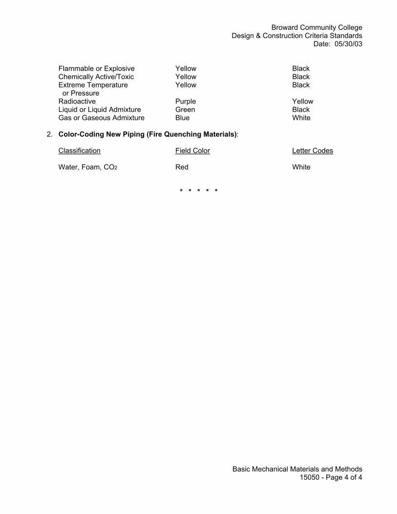
Broward Community College Design & Construction Criteria Standards
Date: 05/30/03
Basic Mechanical Materials and Methods 15050 - Page 4 of 4
Flammable or Explosive Yellow Black Chemically Active/Toxic Yellow Black Extreme Temperature Yellow Black or Pressure Radioactive Purple Yellow Liquid or Liquid Admixture Green Black Gas or Gaseous Admixture Blue White
2. Color-Coding New Piping (Fire Quenching Materials):
Classification Field Color Letter Codes Water, Foam, CO2 Red White
* * * * *

Broward Community College Design & Construction Criteria Standards
Date: 05/30/03
Building Services Piping 15100 - Page 1 of 3
BUILDING SERVICES PIPING SECTION 15100 A. Piping Material: Unless specifically stated otherwise herein, piping material shall be as follows:
1. All piping 2-1/2 inches or less to and from chilled water mains shall be copper Type "L" hard and adapted to the existing cast iron piping with a dielectric fitting between the two dissimilar materials.
2. All piping over 2-1/2 inches shall be welded Schedule 40 black steel. 3. All piping to fan coil units (when approved by the College for use), including drains, shall
be copper Type "L" hard. B. Pipe Insulation: Provide installation only by a licensed insulation contractor. The mechanical contractor may provide insulation on straight runs of pipe. C. Chilled Water Piping: ASTM A53, Schedule 40 steel, Grade B, United States manufacture only. D. Chilled Water Pipe Insulation: 2-inch foamglass or equivalent material approved by the College.
Underground piping shall have all service jacket or "pit wrap".
1. Underground chilled water piping may be pre-insulated PVC "Permapipe" for sizes or lengths that favor this system provided specific approval is granted by the College's Project Manager.
E. Exterior Chilled Water Piping: Finish with a 0.016-inch aluminum jacketing with stainless steel
bands. In addition, provide pipe markers as manufactured by Seton, and flow arrows at 30-foot minimum intervals.
F. Sanitary Sewer Piping: Cast iron bell and spigot for use below grade, and NO-HUB for above
grade installations. Schedule 40 PVC may be used (with College approval) on a single story building. Copper drainage tube (DWV) may be used for waster arms and traps above grade.
G. Hot and Cold Water Piping: Seamless copper, Type "L" above ground, and Type "K" for below
grade installations. Insulate hot water piping with 2-inches of fiberglass with all service jackets. H. Gas Piping: Schedule 40 black steel. Any underground installations shall be sleeved with PVC
pipe. I. Traps: Exposed traps and piping at fixtures shall be chrome plated brass pipe. PVC traps and
waste arms are not permitted. J. Equipment Drains and Condensate: Provide copper DWV above grade and Schedule 40 PVC
below grade. K. Floor Drains: All floor drains except kitchens shall be Josam 3000-S with polished Nikaloy top and
rap primers. Kitchen drains shall comply with DHRS and local health department requirements.

Broward Community College Design & Construction Criteria Standards
Date: 05/30/03
Building Services Piping 15100 - Page 2 of 3
L. Hose Bibs: Provide with vacuum breakers and key-operated stems. On building exteriors, provide
recessed wall boxes or hydrants. M. Water Service Connectors: Protect with reduced pressure backflow preventers, as well as
connection to equipment as required. N. Water Hammer Arrestors: Provide on each fixture and group of fixtures, and at the end of supply
lines to prevent water from "hammering" in pipes in accordance with PDI Standard WH201. Do not use air chambers.
O. Valves: All valves 2-1/2-inch and smaller shall be NIBCO S-136 or approved equivalent. Valves
over 2-1/2 inches shall be NIBCO F619. P. Fittings: For copper piping (except drains), provide fittings brazed with SIL-FOS (minimum 15%
silver). Q. Insulation: Provide pipe insulation as follows:
1. Copper Piping 2-inches and under shall be insulated with 3/4-inch RUBATEX R-180-FS, 25/50 rated.
2. Piping over 2-inches shall be insulated with 1-inch urethane foam such as Owners-Corning Type 50 or Type 75, or approved equivalent.
3. Labeling: All insulated piping shall have "Asbestos Free" labels every 25 feet. 4. Protection: Install insulation protection saddles at all pipe hangers
R. Accessories:
1. Strainers: Brass body, Type #352, 1/2 for silver brazing as manufactured by Muessco Co. 2. Hydronic Circuit Balancing Valve: "CBV" as manufactured by Armstrong. 3. Thermometers: Provide units with angle pattern, 9-inch scale, and separable sockets as
manufactured by Marshalltown, Taylor, or approved equivalent. Scale to be 0-100 degrees F. 4. Pressure Gauges: Provide units with 4-1/2 inch faces, all brass movement, and steel cases
as manufactured by Marshalltown, Taylor, or approved equivalent. Range to be 0-100 psi. S. Installation:
1. Gas Piping: Never embed piping in concrete.
a. Avoid running gas piping under concrete slabs. b. Never run gas piping in or above interior corridors or stairwells, or in any part of the
building identified as a means of egress. 2. Drains: Provide units with shut-off valves at low points in the piping system. 3. Vents: Provide vents with shut-off valves at high points in the piping system. 4. Wet Taps: All wet taps shall be welded and be performed on weekends.

Broward Community College Design & Construction Criteria Standards
Date: 05/30/03
Building Services Piping 15100 - Page 3 of 3
T. Testing Procedures: Thoroughly flush and leak test completed piping systems before any connections are made to equipment or existing chilled water lines. Perform leak test using 125 PSIG nitrogen for a minimum of 24 hours and all joints soap tested.
* * * * *
Broward Community College Design & Construction Criteria Standards
Date: 05/30/2003
Fire Protection 15300 - Page 1 of 1
FIRE PROTECTION SECTION 15300 A. Sprinkler Systems: Provide automatic systems designed, installed and tested in accor-
dance with NFPA Pamphlet 13, "Standards for the Installation of Sprinkler Systems". B. Compliance: All work shall comply with applicable NFPA standards and the Florida Fire
Prevention Code (including all current revisions) C. Food Preparation Areas: All areas equipped with grills and/or deep fryers require total fire
protection in accordance with the Florida Fire Prevention Code, NFPA Pamphlets 96 and 17, and Factory Mutual requirements.
D. Standpipe and Fire Hose Systems: Comply with NFPA Pamphlet 14, "Standards of Instal-
lation of Standpipe and Hose Systems". Provide Siamese pumper connections wherever standpipes are installed.
E. System Design: Design and equipment selection shall meet the requirements of the Florida
Building Code and the Florida Fire Prevention Code (including all current revisions). All electrical components used in conjunction with fire protection systems shall be UL listed.
F. Documentation: All fire protection design and installation drawings shall be prepared to
provide full details of the proposed installation.
1. Flow Tests: Perform flow tests prior to preparing hydraulic calculations. Submit test re-sults to the College's Project Manager.
2. Hydraulic Calculations: All calculations as well as the fire protection drawings shall be signed and sealed by a Florida certified fire protection engineer.
* * * * *
Broward Community College Design & Construction Criteria Standards
Date: 05/30/03
Plumbing Fixtures and Equipment 15410 - Page 1 of 1
PLUMBING FIXTURES AND EQUIPMENT SECTION 15410 A. Program Requirements: This Section identifies the specific plumbing fixture types and
associated accessories for various functional areas found at the College. B. Manufacturers: Provide fixtures and equipment from the following:
1. Fixtures: Eljer, American Standard, or Kholer 2. Flush Valves: Sloan, Royal, or Regal
a. North Campus: Provide flush valves by Chicago Faucets C. Student or Public Toilet Rooms:
1. Water Closet: #111-4605, "Ultra One" as manufactured by Eljer. Provide with "Ultra" water saver siphon jet elongated bowl, 1-1/2-inch top spud, Delany #1302-3 water saver sensor operated flush valve with solenoid and GFI, UL listed. Provide #124-0355 white, open front seat without cover and two (2) bolt caps.
2. Water Closet (Handicapped): #111-1245, "Hi San" as manufactured by Eljer. Provide with 18-inch high, water saver, siphon jet elongated bowl, 1-1/2-inch top spud, Delany #1302-3 water saver sensor operated flush valve with solenoid and GFI, UL listed. Provide #124-0355 white, open front seat without cover and two (2) bolt caps.
3. Urinal: #161-1060, "Correcto" vitreous china, wall-hung as manufactured by Eljer. Provide with blowout, 1-1/4-inch top spud, Delany #1352-3 water saver sensor operated flush valve with solenoid and GFI, UL listed. Provide Josam Series 17810 chair carrier.
4. Lavatory (Group Toilets): Countertop model, #051-3514, "Laura" as manufactured by Eljer. 20" x 17" vitreous china self-rimming oval lavatory modified for one hole, SF-1590. Provide with Delany chrome-plated faucet, 0.5 GPM aerator and built-in sensor with range adjustment, solenoid valve and transformer, UL listed. Provide with #327 Chicago open grid strainer, 1-1/4-inch, 17 gage C.P. "P" trap and escutcheon.
5. Lavatory (Handicapped): #051-2964, wheelchair model as manufactured by Eljer. 27" x 20", vitreous china, wall-hung for concealed arm carrier. Provide with Delany #SF-1590 chrome plated faucet, 0.5 GPM aerator, built-in sensor with range adjustment, solenoid valve and transformer, UL listed. Provide #803-0530, Chicago, cast brass, C.P. strainer with 1-1/4-inch offset drain assembly. Provide 1-1/4-inch, 17 gage C.P. "P" trap and escutcheon, and #17100-67 Josam lavatory carrier with concealed arms.
D. Staff or Private Toilet Rooms:
1. Water Closet: #111-4605, "Ultra One" as manufactured by Eljer. Provide with "Ultra" water saver siphon jet elongated bowl, 1-1/2-inch top spud, Delany #410-3 water saver flush valve. Provide #124-0355 white, open front seat without cover and two (2) bolt caps.
2. Water Closet (Handicapped): #111-1245, "Hi San" as manufactured by Eljer. Provide with 18-inch high, water saver, siphon jet, elongated bowl, 1-1/2-inch top spud, Delany #410-3 flush valve. Provide #124-0355 white, open front seat without cover and two (2) bolt caps.
Broward Community College Design & Construction Criteria Standards
Date: 05/30/03
Plumbing Fixtures and Equipment 15410 - Page 2 of 2
3. Lavatory - Countertop: Model #051-3514, "Laura" as manufactured by Eljer. 20" x 17" vitreous china self-rimming oval lavatory, hole 4-inches on center. Provide with #409-E12 Chicago "Tip Tap" slow-closing faucet, E-1R aerator, #327 Chicago open grid strainer. Provide 17 gage C.P. "P" trap and escutcheon and Josam Series 17100 chair carrier.
4. Lavatory - Wall Hung: #051-1541 "Delwyn" as manufactured by Eljer. 20" x 18" vitreous china for concealed arm, single hole punched, with #SF1590 Delany chrome-plated faucet, 0.5 GPM aerator and built-in sensor with range adjustment, solenoid valve and transformer, UL listed. Provide with #327 Chicago open grid strainer, 1-1/4-inch 17 gage C.P. "P" trap and escutcheon, and Josam Series #17100 chair carrier.
5. Lavatory (Handicapped): #051-2964, wheelchair model as manufactured by Eljer. 27" x 20", vitreous china, wall-hung for concealed arm carrier. Provide with #785 Chicago fitting with #317, 4-inch wrist blade handles, and #GN-1A swing convertible gooseneck spout, and #E-2605, 1/2 GPM aerator. Provide #803-0530, Chicago, cast brass, C.P. strainer with 1-1/4-inch offset drain assembly. Provide 1-1/4-inch, 17 gage C.P. "P" trap and escutcheon, and #17100-67 Josam lavatory carrier with concealed arms.
E. Shower Facilities: Provide shower fixtures and accessories for the following uses:
1. Student: #1743 Acorn, wall mounted with vandal-resistant shower head, 2.5 GPM flow control, pushbutton panel modified to receive infrared sensor and valve, solenoid and transformer, UL listed. Provide 2-inch chrome-plated drain.
2. Student (Handicapped): #1741-3 Acorn, HCP-M shower panel, pushbutton type, modified to receive infrared sensor and valve, solenoid and transformer, UL listed. Provide fixed showerhead with 2.5 GPM flow resrictor, and hand-held shower with flexible stainless steel hose. Provide pan and 2-inch drain.
3. Staff: Acorn "Safti-Therm", anti-scald shower unit with multi-stream head, 3 GPM flow restrictor and angle stops. Provide pan and 2-inch chrome-plated drain.
F. Miscellaneous: Provide other fixtures as required by educational specifications and College
requirements including the following:
1. Mop Receptor: Williams Serviceptor, Model #SB-900, 24" x 24" x 12" with 3-inch cast brass waste. Provide with Chicago #305 V.B.R. rough-plated faucet with hose end, pail hook, vacuum breaker and stops.
2. Electric Water Cooler: Haws "HCBF 7D" wheelchair cooler. Provide with compressor motor that has thermal and overload protection, vandal-proof bubbler, adjustable automatic regulator and drinking water thermostat. Unit shall be guaranteed for five (5) years. Provide with 1-1/4-inch cast brass "P" trap with cleanout and 1/2-inch C.P. supply and stop with escutcheon. Provide certification that no lead solder has been used in the fabrication of the waterways or the refrigeration equipment.
3. Shower Control Panel: Powers "Hyproguard 432" master mixing valve with check stops, ball valves for 90 degree shut-off. Provide with volume control dial thermometer, rough-bronze piping and components, and stainless steel recessed cabinet with key.
* * * * *

Broward Community College Design & Construction Criteria Standards
Date: 05/30/2003
Refrigeration 15600 - Page 1 of 2
REFRIGERATION SECTION 15600 CHILLERS - 15610 A. Chiller Selection: Select units suitable for HCFC-123, HFC-134A or other EPA approved
refrigerant. Consider selecting only centrifugal water-cooled or reciprocating chillers. B. Energy Rebates: Look at possible utility company rebate programs and/or thermal storage
applications when feasible. C. Owner Furnished Equipment: All chillers will be procured by the College and provided to
the Contractor. D. Design: Each campus utilizes a central chiller plant. Evaluate connected load and impact of
new building load as applicable. E. Sizing Components: Size chiller pumps and fans at design load. Do not oversize in accor-
dance with FECM Chapter 2, Section 1, Paragraph B-8. F. Control Reset: Provide with each unit so that the chilled water supply temperature can have
the capability of being varied relative to the chilled water return temperature. G. Chiller Schematics: Schematics for a typical centrifugal water chiller installation at the Col-
lege are attached to this Section. COOLING TOWERS - 15640 A. Unit Type: Provide factory-assembled, induced draft, crossflow-cooling towers with vertical
air discharge constructed of Type 304 stainless steel. B. Preferred Model/Manufacturer: Model Series 1500 Cooling Towers as manufactured by
Baltimore Aircoil. C. Schematics: Cooling tower schematics are attached to this Section. D. Casing: Provide casing constructed entirely from Type 304 stainless steel panels. E. Access: Provide a hinged access door on the end wall of the tower for access to eliminators
and fan plenum section. Access door shall be fabricated from Type 304 stainless steel. F. Cold Water Basin: Provide basin fabricated from Type 304 stainless steel. Basin includes
a depressed section with drain and clean-out connection. G. Make-up Float Assembly: Provide a bronze make-up valve with unsinkable polystyrene
filled plastic float arranged for easy adjustment. The make-up valve shall be suitable for pub-lic water supply pressures between 15 and 50 psig.

Broward Community College Design & Construction Criteria Standards
Date: 05/30/2003
Refrigeration 15600 - Page 2 of 2
H. Strainer: Provide a large-area, lift-out, hot-dip galvanized steel strainer screen with perfo-
rated openings sized smaller than the water distribution nozzle orifices, and easily accessi-ble from the base of the unit. Include anti-vortexing baffle to prevent air entrainment.
I. Air Inlet Louvers: Provide fiberglass-reinforced polyester (FRP) louvers spaced to minimize
air resistance and prevent water splash out. J. Water Distribution System: Hot water distribution basin shall be open gravity type con-
structed of heavy gauge, hot-dip galvanized steel. Provide with a pre-strainer with perfo-rated openings sized smaller than the water distribution nozzle orifices. Provide polypropyl-ene metering orifices to assure even distribution of water over the wet deck surface. Pro-vide with heavy-gauge, hot-dip galvanized steel covers to allow access to the water distribu-tion system from the side of the unit.
K. Fan Drive System: Fans shall be driven by a one-piece multi-groove, neoprene/polyester
belt designed specifically for cooling tower service. Fan sheave shall be of aluminum con-struction. Motor sheave shall be protected from moist discharge air by a vented enclosure.
L. Fan Shafts and Bearings: Provide fan(s) and solid steel fan shaft(s) supported by heavy-
duty, self-aligning, grease-lubricated, re-lubricatable ball bearings with special seals for pro-tection against dust and moisture, and integral slinger rings. All bearings shall be designed for a minimum L10 life of 40,000 hours.
M. Fan and Fan Cylinder: Fan(s) shall be fixed pitch, heavy-duty, cast aluminum, axial flow
types. Fan cylinders shall be heavy-gauge, hot-dip galvanized, designed for streamlined air entry and minimum tip clearances for maximum fan efficiency.
N. Fan Guard: Provide a heavy-gauge, hot-dip galvanized wire fan guard over each fan cylin-
der. O. Motor: Provide totally enclosed unit with air-over (TEAO), reversible squirrel cage (ball bear-
ing type) designed specifically for cooling tower service. Provide motor with special mois-ture protection on windings, shafts, and bearings.
P. Wet Deck Surface and Drift Eliminators: Fabricate from polyvinyl chloride (PVC). Com-
ponents shall be impervious to rot, decay, fungus or biological attack, and have a flame spread rating of 5 in accordance with ASTM E84-77a. Eliminators shall be designed to ef-fectively strip entrained moisture from the leaving air stream with a minimum of air resis-tance. Wet deck shall be suitable for a maximum entering water temperature of 120 de-grees F.
Q. Corrosion Protection: All steel components of the cooling tower shall be Type 304 stain-
less steel with cut edges and other exposed surfaces coated with a zinc-rich compound.
* * * * *

Broward Community College Design & Construction Criteria Standards
Date: 05/30/03
HVAC and Air Distribution 15700 - Page 1 of 3
HAVC AND AIR DISTRIBUTION SECTION 15700 AIR HANDLING UNITS - 15720 A. Submittals: Coordinate with requirements of Section 01300 Administrative Requirements for
Shop Drawings, Product Data and Samples.
1. Shop Drawings: Submit dimensioned and detailed shop drawings showing compliance with criteria, location within mechanical room, including free clearances and space available for changing filters and cooling coils. Include design calculations.
2. Product Data: For each type of central station air handling unit, listing performance criteria and material specifications, including heat pipe coils, wiring diagrams and control schematics for variable frequency drives.
3. Operation and Maintenance Data B. Unit Casing
1. Construction: Entire unit shall be solid double-wall panel construction. Exterior panel shall be minimum 18 gage galvanized steel; interior shall be minimum 20 gage galvanized steel. Casing panels shall be removable for access.
2. Insulation: Unit shall be factory-insulated between the interior and exterior panels with a minimum 2-inch thick, 2-lb. density insulating material meeting NFPA-90A requirements for flame spread and smoke development. All connecting channels shall be insulated to prevent sweating.
3. Hinged Access Doors: Provide on both entering air and leaving airsides of the cooling coil. C. Coil Section 1. Cooling Coils: Chilled water type selected on the basis of providing a delta-T of 15 degrees
F. Capacity and size shall be as required to provide the required HVAC performance for the Project. Coils shall be removable from the unit casing and be supported their entire length in track.
2. Drain Pan: Provide units with double wall insulated sloped stainless steel drain pan with threaded connections extending under the entire coil component. Drain pan insulation shall comply with NFPA-90A for flame spread and smoke development.
3. Coils: Provide copper tubing for all coils. Aluminum or copper plate fins shall be firmly bonded to copper tubes by mechanical expansion of tubes.
a. Water coils shall be drainable and have non-tapping circuits. b. Coils shall have same-end connection and be factory-burst and leak tested. c. Coils shall be certified in accordance with ARI 410. D. Fan Section 1. Formed Channel Base: Provide for integral mounting of fan, motor, and casing panels.

Broward Community College Design & Construction Criteria Standards
Date: 05/30/03
HVAC and Air Distribution 15700 - Page 2 of 3
2. Access Door: Provide hinged types on either side of the fan section to permit uninhibited maintenance access.
3. Fan: Scroll and bearings shall be mounted on a frame secured to the channel base.
a. Provide removable panel on the front (drive side) of the unit to permit removal of fan wheel, motor and drive.
b. Bearings shall be externally mounted, self-aligning, ball type selected for an average design life of 200,000 hours of operation.
c. Fan wheels shall be keyed to a solid steel, ground and polished, shaft. d. Fans shall be ARI Standard 430 certified, double-width, double inlet multi-blade centrifugal
types, statically and dynamically balanced. Fan style shall be forward curved. e. Provide bonderized steel wheels painted with baked-on enamel, or unpainted hot-dipped
galvanized steel, mill finish. E. Motors 1. Motors: Provide NEMA premium efficiency types with a motor service factor not less than
1.15, arranged to operate continuously under full load in an ambient temperature of 40 degrees C.
a. Provide motors with copper windings and internal thermal overload protection b. Mount motors on integral isolated fan assemblies furnished by the unit manufacturer.
Motors shall be mounted inside or on top of the basic casing c. Provide variable frequency drives for all VAV system motors (refer to Electrical Section
16220 – Motors for additional requirements)
2. Lubrication: Provide external grease fittings. Plugs will not be accepted. F. Filter Section 1. Frames: Properly sized for the filter thickness with necessary reinforcement to properly
support the filters. 2. Filter Section: Provide both 2-inch pleated pre-filters and 12-inch deep cartridge filters.
Provide hinged access doors on both sides. 3. Filters: Provide 30-30 pre-filter with 65% efficiency cartridge type filters. Efficiency to be
based on ASHRAE 52-76 standard. G. Heat Pipes 1. Manufacturer: Provide 2-row heat pipes by Heat Pipe Technologies or equivalent
manufacturer.
a. Unit shall provide 9.6 degree F pre-cool and 9.6 degree F re-heat. b. Placement: Wrap around chilled water, cooling coil for the purpose of pre-cooling, re-
heating, increasing dehumidification, and increasing energy savings. 2. Energy Consumption: Provide passive device consuming no electrical energy, constructed
of micro-grooved copper tubing with aluminum fins.

Broward Community College Design & Construction Criteria Standards
Date: 05/30/03
HVAC and Air Distribution 15700 - Page 3 of 3
3. Circuits: Individually evacuated and properly charged with refrigerant, sealed and tested for proper operation.
H. Internal Isolation: Provide spring vibration isolators for fan, motor and drive assemblies. I. Drives 1. General: Drives shall be selected at 1.4 service factor and shall be variable pitch, suitable for
adjustment within 5% of the specified RPM. 2. Centerline Distances: Do not exceed three (3) times the sum of the sheave diameters, or
less than the diameter of the larger sheave. 3. Belt Speed: Between 1000 and 5000 feet per minute. 4. Belt Contact Area: Not less than 120 degrees on the smaller sheave. All adjustable pitch
drives with four grooves shall have matching companion sheaves. 5. Variable Speed Controller: Variable speed type designed to operate from a 460 volt (+10% -
5%) 3-phase, 60 hertz power supply and control a squirrel cage motor via pulse width modulation (PWM), with a corresponding voltage rating.
J. Anchorage: Secure all air-handling units to concrete equipment pads using anchor bolts. AIR DISTRIBUTION DUCTWORK - 15810 A. Fabrication: Ductwork shall be galvanized sheet metal fabricated in accordance with SMACNA,
latest edition. B. Branch Takeoffs: Provide rectangular sheet metal, supply air and return air ducts with 45-degree
shoetaps and volume dampers. At all branch takeoffs where 45-degree shoetaps are not appropriate, provide round bellmouth takeoffs with volume dampers, but only up to medium pressure ducts. No other types of takeoff will be approved.
C. Round Duct: The use of round factory-fabricated double wall duct and fittings are permissible. D. Insulation: Fiberglass with a foil vapor jacket. Do not use internal duct liner. E. Sound Attenuation: If required, use either duct-mounted noise attenuators or lead-lined foam
insulation. F. Smoke Detectors: Provide on both the supply and return air sides of air-handling units whether
ducted or free. Provide a supply air smoke detector upstream (before) of electric duct heaters. Provide a return air smoke detector before the outside air intake. In addition, if both the supply air and return air are ducted to the air-handling unit, than a heat detector will also be required in the mechanical room.
G. Flexible Duct: Provide in as short a length as possible when used. In no case shall the length
exceed 8-feet. Installed flexible duct shall not lie flat on top of the ceiling and shall not have any insulation exposed to the air-stream.
* * * * *

Broward Community College Design & Construction Criteria Standards
Date: 05/30/03
Direct Digital Controls 15910 - Page 1 of 1
DIRECT DIGITAL CONTROLS SECTION 15910 A. System Description: Provide direct digital control (DDC) system as manufactured by Andover
Controls (no substitutions), with Modem - Mate as required.
1. Provide 2-way chilled water control valves with "Belimo" actuators. 2. Provide a written full sequence of operation 3. Provide control schematic diagrams for each air-handling unit, exhaust fan, supply fan,
variable air volume (VAV) box, chillers, cooling tower and pumps. B. Accessibility: All DDC control panels and control valves shall be floor accessible in the
mechanical or electrical room. C. System: Andover "Infinett II" CX90000 LAN, with the following controllers. Manufacturer's system
literature is attached.
1. I2800i for inputs 2. I2800 for fan coil units 3. I2810 and I2920 for air handling units and chillers 4. I2865 for VAV controllers
* * * * *

Broward Community College Design & Construction Criteria Standards
Date: 05/30/03
Division Title - Electrical Page 1 of 1
ELECTRICAL

Broward Community College Design & Construction Criteria Standards
Date: 05/30/2003
Electrical Design Requirements 16000 - Page 1 of 3
ELECTRICAL DESIGN REQUIREMENTS SECTION 16000 ELECTRICAL DESIGN, GENERAL - 16010 A. Design Approach: Incorporate life-cycle considerations and a holistic approach with re-
spect to energy conservation, properly proportioned demand load considerations, emer-gency power requirements, and power quality needs. Avoid over-designing of systems.
B. Related Work: All Electrical work to be performed shall be reflected in Division-16 specifica-
tions and/or on the Electrical Drawings. Any required electrical work related to other Divi-sions of the specifications shall be shown on the Electrical Drawings and specified in Divi-sion-16.
C. Division-13 Work: All work provided under Division-13 related to system equipment, de-
vices, conduit, wiring, etc., that is required by the nature of the work to conform to Division-16 requirements, shall be included in Division-13.
1. All work provided under Division-13 shall be provided by the contractor supplying, fur-
nishing, and/or installing the requirements of the Division-13 work. D. Existing Drawings: Drawings of existing facilities and underground utilities or systems may
not be accurate and shall be considered as informational only. Architect/Engineer shall ver-ify field conditions applicable to the Project design to the extent existing conditions are not concealed.
E. IEEE 1100-1992: Required criteria for the design of all Division-16 electrical systems. F. Communications and Data Systems: The Architect/Engineer shall provide access points
and outlets for these systems in the facility design. Coordinate communications and data systems design and communication duct bank design with the College Project Manger.
G. Ceiling Space: The design shall provide adequate space above corridor ceilings for electri-
cal power, signaling, communications, data, and security systems installations. H. Clear Space: The Architect/Engineer shall be responsible for determining locations and
meeting any clear space and in-sight requirements for the installation of electrical equip-ment. Contract documents shall leave no question that clear space requirements can be met, especially at duct heater terminal cabinets and HVAC VAV boxes.
I. Branch Circuit Design: Where anticipated loads are comprised of a high proportion of
equipment utilizing switched-mode power supplies, design in conformance to NEC 1999, 210-4 (FPN).
J. Separate Neutrals: Where fixtures with electronic ballasts are used, and for receptacles
intended for the connection of computers or peripheral equipment in administrative or class-

Broward Community College Design & Construction Criteria Standards
Date: 05/30/2003
Electrical Design Requirements 16000 - Page 2 of 3
room space, specify separate neutrals on all such circuits. Shared neutrals will not be ac-ceptable.
K. Products: Equipment and materials of the same type of classification and used for the
same purpose shall be products of the same manufacturer. L. Classrooms and Instructional Spaces: Provide communications/data infrastructure con-
sisting of lighting with motion detection sensors, emergency power, lighting control, audio-visual, voice, data and electrical distribution.
1. Audio-visual screens shall be electrically powered at the Central Campus. 2. Multi-media: Provide connectivity for a classroom multi-media podium and an empty
conduit for television installation 3. Voice Evacuation System: Provide for public assembly areas such as lecture halls,
auditoriums and libraries 4. Laboratories: Provide electrical power to all lab tables from adjacent wall surfaces in in-
stances where the laboratory does not have a raised floor system. Ceiling drops for electrical power shall not be used under any circumstances without the College Project Manager's written authorization.
M. UL Approval: All electrical current consuming or generating equipment shall be UL ap-
proved and have a UL label containing registration numbers. Where materials do not bear a UL label, a certificate of compliance shall be furnished with the equipment submittals.
N. Coordinated Short Circuit Current Calculations: The Architect/Engineer shall perform to
determine the proper sizing of circuit breakers in accordance with NEC Section 110-9 and 110-10. Submit calculations to the College for review prior to final construction document submittal. Include calculations on the Electrical Drawings.
O. Voltage Drop Calculations: To meet NEC recommended minimum of 3 percent voltage
drop, the Architect/Engineer shall specify the following:
1. #12 Wire: 120V 20A circuit 0 to 50 feet to the farthest outlet; 277V 20A circuit 0 to 100 feet to the farthest outlet.
2. #10 Wire: 120V 20A circuit 51 to 90 feet to the farthest outlet; 277V 20A circuit 101 to 200 feet to the farthest outlet.
3. #8 Wire: 120V 20A circuit 91 to 140 feet to the farthest outlet; 277V 20A circuit 201 to 300 feet to the farthest outlet.
4. Electrical design shall preclude any panel runs supplying these circuits from exceeding the maximum distances and associated wire sizes noted above.
P. Aluminum products and materials including, but not limited to, raceways, boxes, and fittings
are not acceptable of permitted for electrical work. ELECTRICAL AND COMMUNICATION ROOM REQUIREMENTS - 16025 A. Space: Maximum allowable space shall be allotted to electrical and communications/data
equipment rooms to provide ample clear space for the equipment provided and for future needs.
Broward Community College Design & Construction Criteria Standards
Date: 05/30/2003
Electrical Design Requirements 16000 - Page 3 of 3
1. Communications/data equipment rooms shall be a minimum of 10-feet by 12-feet; mini-
mum size for closets shall be 8-feet by 10-feet. 2. Communications/data equipment rooms are not to be calculated as part of the 6 percent
space allocation for electrical and mechanical space under State Requirements for Edu-cational Facilities.
3. Communications/data equipment rooms are to be include in the net square foot area of the facility that is used to calculate the 6 percent space allocation for electrical and me-chanical space.
4. Provide 20 percent additional wall space for future expansion. B. Drawings: Construction drawings shall contain enlarged floor plans at 1/2-inch scale of all
electrical and communications/data equipment rooms and closets showing the location of all equipment in these spaces.
C. Air-conditioning and Ventilation: Provide all telephone equipment and communica-
tions/data equipment rooms and closets with 24-hour air-conditioning. Provide all electrical rooms and closets with air-conditioning unless provided with positive outside air ventilation.
1. Positive outside air ventilation shall utilize an exhaust fan and provide maximum filtering
of incoming make-up air to exclude dirt, dust and other deleterious air-borne substances. 2. Dropped ceilings are not permitted in electrical and communications equipment rooms.
D. Doors: All electrical and communications/data equipment room doors shall swing out, pref-
erably to the exterior of the facility. E. Raceways: Terminate immediately adjacent to the cable trays or backboards. All conduit
type raceways, including through the floor stubs, shall terminate in an insulated throat, lay-in lug bonding bushing (RACO 1213, or equivalent).
F. Data/Com Outlets: Provide one in each electrical distribution room.
1. Provide a 3/4-inch conduit with pull string from each data/com outlet and from each se-curity junction box to the telephone/communications/data backboard.
2. Five (5) data/com outlet 3/4-inch conduits may be grouped into a 12" x 12" x 6" junction box with a 2-1/2 inch conduit with pull string run to the telephone/communications/data backboard.
G. Conduit: There shall be no more than two (2) 90-degree bends, or a total of 180-degrees of
bends in a communications conduit run from termination point to termination point. H. Data/Com Outlets: All flush wall data/com outlets shall be installed with a 4-11/16" square
and 2-1/8" deep knockout box with a two gang plaster ring finished plumb and flush with the finished wall.
* * * * *
Broward Community College Design & Construction Criteria Standards
Date: 05/30/2003
Basic Electrical Materials and Methods 16050 - Page 1 of 1
BASIC ELECTRICAL MATERIALS AND METHODS SECTION 16050 GENERAL REQUIREMENTS - 16055 A. Quality Work: Contractor shall maintain the highest level of quality in the performance of
the work. The execution of the work in the installation of electrical equipment shall be per-formed in a neat and workmanlike manner as required by the current edition of NFPA 70, National Electrical Code. The College and the Code authorities having jurisdiction will strictly enforce this requirement. "Area practice" does not relieve the Contractor of the re-sponsibility for conforming to the stated and shown Contract Document requirements.
B. Coordination: Contractor shall coordinate work specified in other Divisions of the specifica-
tions that require electrical installation with the requirements of Division-16 and the contract drawings to ensure all subcontractors involved work together to provide a complete, opera-tional systems at no additional cost to the College.
C. Housekeeping Pads: Provide for all floor-mounted electrical equipment; minimum 4-inches
high, 3000 psi concrete with no greater than a 2-inch lip around the equipment. GROUNDING - 16060 A. Grounding Buss: Copper, 10-inches long, CHATSWORTH #10622-010, no substitutions.
Provide in the Electrical Main Distribution Room and in all other Electrical Distribution rooms and separate Communication/Data rooms.
B. Grounding Path: Provide a metal cold water pipe in each Electrical Main Distribution Room
located near the floor and not above or near any electrical equipment so as to not present a hazard if the pipe should rupture. Provide grounding clamps of the same metal as the water pipe they are connected to.
C. Equipment Grounding Conductors: Provide throughout the Project design. All electric
equipment (metallic conduit, motor frames, panel boards, boxes, etc.) and main switchboard shall be bonded together with a green insulated copper equipment grounding conductor sized per NEC (minimum size #12 AWG).
1. Continuity: Provide continuous bonding conductors through the raceway system from
main switch ground buss to panel board ground buss and to each branch circuit outlet or switch.
2. Equipment grounding conductors shall in no case be run on the exterior of a raceway, on the building surface, or concealed in the building structure.
3. Termination: Terminate equipment grounding conductors in terminal bars, screws, or lugs expressly designed for the purpose.
D. Grounding Buss Installation: Mount 18-inches above the finish floor of the Electrical Main
Distribution Room. Connect to the footer steel, building steel, to two (2) 3/4" diameter by 10-

Broward Community College Design & Construction Criteria Standards
Date: 05/30/2003
Basic Electrical Materials and Methods 16050 - Page 2 of 2
foot long copper-clad driven ground rods, or to the cold water pipe with the proper size cop-per grounding electrode conductor.
1. Interconnect grounding buss to each Electrical Distribution room grounding buss with a
tie conductor of the same size as the main grounding electrode conductor. 2. Connections: Connect the ground buss in each communications room with a minimum
#1/0 copper conductor in 1-inch conduit. E. Grounding Electrode Conductor: Run enclosed in rigid metallic conduit continuous from
the service entrance grounding buss to the grounding electrode. F. Connections and Terminations to the grounding electrode and grounding electrode con-
ductor shall be made by exothermic welding. ELECTRICAL SUPPORTING DEVICES - 16070 A. Performance Requirements: Design supporting devices capable of supporting combined
weight of supported systems and components. Do not use cantilever supports. B. Submittals: Provide shop drawings for fabrication and erection of electrical supporting de-
vices. C. Material, General: Provide cold-formed steel with corrosion-resistant coating acceptable to
authorities having jurisdiction. Use hot-dip galvanized (I-90) steel for outdoor and damp lo-cations or nonmetallic, U-channel system components.
D. Nonmetallic Channel and Angle Systems: Structural-grade, factory-formed, glass-fiber-
resin channels and angles with 9/16-inch diameter holes at a maximum of 8-inches on cen-ter in at least one surface.
E. Raceway and Cable Supports: Manufactured Clevis hangers, riser clamps, straps,
threaded C-clamps with retainers, ceiling trapeze hangers, wall brackets, and spring-steel clamps or click-type hangers.
F. Pipe Sleeves: ASTM A53, Type E, Grade A, Schedule 40, galvanized steel, plain ends. G. Anchors: Powder-actuated fasteners will not be permitted. 1. Expansion Anchors: Carbon-steel wedge or sleeve type 2. Toggle Bolts: All-steel spring-head type H. Installation, General: Securely fasten electrical items and their supports to the building
structure unless otherwise indicated I. Strength of Supports: Adequate to carry present and future loads times a minimum safety
factor of four.

Broward Community College Design & Construction Criteria Standards
Date: 05/30/2003
Basic Electrical Materials and Methods 16050 - Page 3 of 3
1. Size supports for multiple raceway installations so capacity can be increased by a 25 percent minimum in the future
2. Support Clamps for PVC Raceways: Click-type clamp system J. Horizontal Raceways: Support individual raceways with separate, malleable-iron pipe
hangers or clamps. Arrange for grouping of parallel horizontal conduit runs to be supported together at the proper intervals on trapeze type hangers.
K. Threaded Steel Hanger Rods: Minimum 1/4-inch diameter, appropriate for the intended
load. L. Spring-steel Fasteners: Specifically designed for supporting single conduits or tubing; may
be used instead of malleable-iron hangers for 1-1/2 inch and smaller raceways serving light-ing and receptacle branch circuits above suspended ceilings and for fastening raceways to slotted channel and angle supports.
M. Arrangement: Arrange supports in vertical runs so the weight of raceways and enclosed
conductors are carried entirely by raceway supports, with no weight load on raceway termi-nals
N. Metal Channel Racks: Install for mounting cabinets, panel boards, disconnect switches,
control enclosures, pull and junction boxes, transformers, and other devices unless compo-nents are mounted directly to structural elements of adequate strength.
O. Sleeves: Install for cable and raceway penetrations of concrete slabs and wall unless core-
drilled holes are used.
1. Install sleeves for cable and raceway penetrations of masonry and fire-rated gypsum walls and of all other fire-rated floor and wall assemblies.
2. Install sleeves during erection of concrete and masonry walls. P. Wall-Mounted Electrical Equipment: Install surface and wall-mounted equipment on Uni-
strut or equivalent supports, or 3/4-inch exterior B-C grade or better plywood. Refer to Divi-sion 06000, Wood and Plastics for additional requirements for wood backing panels.
ELECTRICAL IDENTIFICATION - 16075 A. General: Tag all conductors and identify major conduits in or at outlets, raceways, panels,
pull boxes, switch boards, motor controllers, cabinets and similar items. Conductor tags shall be non-conductive or Brady-type markers.
B. Junction Boxes: All lighting and power junction boxes shall be identified by circuit and
panelboard number and color-coded in a permanent manner. C. Other Devices: All disconnect switches, panel boards, motor starters, system controllers,
fire alarm zones, transformers, power outlets (other than ordinary receptacles) shall be iden-tified by installing a permanent plastic laminated engraved nameplate with appropriate des-ignation.
Broward Community College Design & Construction Criteria Standards
Date: 05/30/2003
Basic Electrical Materials and Methods 16050 - Page 4 of 4
D. Panel Board Directories: Typewritten indicating the as-built circuit information, and pro-
tected by a plastic covering. All panel schedules shown on the Drawings shall include the following:
1. Location or room number and use indicated for each circuit (as-built documentation shall
show corrected information) 2. Load calculations 3. Panel power source 4. Conduit and conductor size from source
E. Color-Coding: Identify all systems by painting the designated color-code on all junction
boxes and covers using the following system:
1. Normal Power Black 8. Telephone Gray 2. Normal Lighting Blue 9. Sound System Light Blue 3. Emergency Light/Power Red 10. Energy Management Pink 4. Fire Alarm Orange 11. ATC/AC Control System Purple 5. Clock System Green 12. Computer/Conditioned Power Yellow 6. Data Systems White 13. Security Burgundy 7. MATV Systems Brown
F. Post-Installation Identification: Identify concealed electrical systems with a small, adhe-
sive-backed colored dot attached to the ceiling surface below the junction box of the system being identified. Color coding scheme shall be as required under "Color-Coding" above.
* * * * *

Broward Community College Design & Construction Criteria Standards
Date: 05/30/2003
Wiring Methods 16100 - Page 1 of 1
WIRING METHODS SECTION 16100 WIRE - 16120 A. Neutrals: Separate neutrals are a requirement. Common neutrals shall not be used. B. Wire Size: 120 volt/20 amp branch circuits supplying lighting, receptacles exceeding 100
feet from the overcurrent device to the first outlet, and all 277 volt/20 amp lighting circuits exceeding 150 feet from the overcurrent device to the first outlet shall be #10 AWG for the entire branch circuit. Circuits exceeding 200 feet to the first outlet shall be #8 AWG for the entire branch circuit.
C. Grounding: Provide a copper equipment grounding conductor of the proper size in all
power and lighting branch circuit and feeder raceways. This wire is in addition to conduits and other raceway ground paths.
1. Minimum size of the equipment grounding conductor shall be #12 copper 2. A 10/32 green screw shall be used to ground all outlet boxes
D. Wire and Cable shall be annealed, coated copper per ASTM B33 or ASTM B189 with con-
ductivity or not less than 98 percent.
1. Provide Stranded Class B wire and cable per ASTM B8 2. Bus, lugs, and terminal blocks shall be copper 3. Aluminum wire and cable will not be permitted
E. Conductor Insulation: UL Type THHN or THWN, or provide UL Type THW or XHHW as
appropriate for locations where installed. F. Color-Coding: Provide color insulation or suitable colored permanent non-aging insulation
tape equal to Scotch #461 applied to, and covering 6-inches of, the conductors at each out-let, cabinet or junction box. The following color-coding shall be followed:
1. Ground leads Green 2. Neutral Conductors White (120/208V); Gray (277/480V) 3. Phase A, B, C 120/208V Black, Red, Blue 4. Phase A, B, C 277/480V Brown, Orange, Yellow G. Conductors: Run in approved conduit system regardless of voltage or insulation.
1. Lugs: Use approved types on all stranded or solid conductors 2. Bundling: Conductors located in branch circuit panel boards, cabinets, and control
equipment shall be bundled neatly and securely using plastic cable tie-wraps, or an equivalent method

Broward Community College Design & Construction Criteria Standards
Date: 05/30/2003
Wiring Methods 16100 - Page 2 of 2
H. Wires: Not more than five (5) wires, including the equipment grounding conductor, shall be installed in a conduit run except by written authorization from the College Project Manger.
I. Splices: Provide sleeves using hydraulic Hy-Press methods for splices made in conductors
#4 AWG and larger.
I. No splicing will be permitted on fire alarm, clock, speaker, intercom, or TV systems wiring. All splicing on these types of systems shall be made in junction boxes on the proper termination strips.
RACEWAYS - 16130 A. Locations, Types, and Sizes:
1. All raceways above slab or ground shall be metallic. 2. All systems for lighting, heat, power, or controls shall be installed in 3/4-inch trade size
raceways with minimum 3/4-inch, trade size home runs. 3. All branch circuit home runs shall be 3/4-inch minimum trade size containing not more
than one four-wire multi-wire branch circuit plus an equipment grounding conductor (if required) and shall be clearly indicated as such on the Drawings.
4. All raceways below grade or under slabs shall be a minimum of 3/4-inch trade size. B. Aluminum: No aluminum raceways will be permitted. C. Rigid Galvanized Steel Conduit (RGS): Use where conduit is exposed and subjected to
the weather or potential physical damage. D. Conduit: Provide rigid steel conduit, in, below, or through concrete floor slabs, vapor barri-
ers, and in masonry or concrete walls. Protect conduit utilizing one of the following meth-ods:
1. Field-coated with two coats of bitumastic compound 2. Additional outside factory coating of polyvinyl chloride, phenolic-resin-epoxy material,
or other equally flexible and chemical resistant material E. Schedule 40 PVC, clearly identified, 1-1/4-inch and larger size conduit, encased in a 2-inch
minimum envelope of concrete, buried to a minimum depth of 24-inches to the top of the concrete envelope, may be used in concrete slabs, and under buildings, grassed areas and parking areas.
F. EMT (Electrical Metallic Tubing): May be used for all indoor work from the switch and re-
ceptacle level up.
1. All fittings shall be steel without exception, conforming to ANSI C80.4. 2. Where concealed, fittings may be set-screw type with insulated throat connectors hav-
ing two (2) set screws in line at each tubing connection for sizes 1-1/4 to 2-inches, and two (2) set screws 45 degrees apart at each tubing connection for sizes 2-1/2 to 4-inches.

Broward Community College Design & Construction Criteria Standards
Date: 05/30/2003
Wiring Methods 16100 - Page 3 of 3
3. Provide steel compression type, UL listed fittings for rain-tight applications, with insu-lated throat and casehardened locknuts.
4. Where EMT is used in concrete slabs, or through concrete, all stub-ups shall be RGS. 5. The connection of power or communications outlets within permanently installed cabi-
nets and casework shall be concealed and run in EMT. 6. Acceptable Manufactures of EMT: Appleton, Raco, Thomas & Betts, and Efcor
G. Exposed Connections: Provide Liquidtight Flexible Metal Conduit, 24-inch maximum
length in mechanical rooms, damp and wet locations, or where flexible connections are re-quired.
1. Connectors: steel, UL listed for grounding, metallic applications, or non-metallic appli-
cations. Only fittings identified for the use will be acceptable. 2. Where flexible connections require 2-inch to 4-inch trade size, provide Flexel as manu-
factured by O-Z/GEDNEY or equivalent. H. Flexible Metal Raceways: Shall not be used to extend a raceway system, or for the con-
nection of outlets within permanently installed cabinets or casework. Flexible metal race-ways shall be steel (no aluminum will be permitted).
1. May be used only where they will be concealed but accessible 2. May be used for the connection of recessed lighting fixtures where a maximum run of
6-feet will be permitted I. Fittings: Steel and UL listed when used for grounding. No die-cast or pot metal fittings will
be permitted. J. Cable Tray: Use of cable tray is not acceptable unless approved by the College. In those
instances where the College has approved the use of cable tray, provide in continuous runs without gaps, field-fabricated fittings, or bends. Only manufactured fittings will be accept-able. Installed cable tray shall be easily accessible with a minimum of 2-feet clear on each side.
K. Surface-Mounted Raceways: Provide a fabricated trough or enclosure with a screw cover
to house or enclose data cables, communications cables, and power raceways.
1. Locate to provide easy access for servicing or future expansion or modification of the enclosed systems
2. Provide grommets for power, data and communications cables at proper locations. Size shall be 1-3/4 inches or 2-inches as required.
L. Installation, General: There shall be no bends exceeding 90 degrees in any conduit run. M. Stub-Outs: Provide four (4) spare 3/4-inch conduit stub-outs from each panel board and
telephone board into the nearest accessible ceiling space. N. Pull Wire: Provide a pull wire in all empty raceways. Pull wire shall be #14 TW, Thomas
Industries Jet Line #232 Polyofin 200 lb. Test, or equivalent.
Broward Community College Design & Construction Criteria Standards
Date: 05/30/2003
Wiring Methods 16100 - Page 4 of 4
O. Raceways penetrating walls or floors through sleeves shall be sealed and fire-stopped. Re-fer to Section 07800, Fire and Smoke Protection, for additional requirements.
P. Conductors or circuits of differing voltages (i.e., 120/208VAC or 277/480VAC, or Class 1,
Class 2, and Class 3 Remote-Control, Signaling, and Power Limited circuits, or circuits originating in different panel boards) shall not be installed or contained in the same conduit run.
Q. Architectural Woodwork: Provide a trough or enclosure with a screw cover to house or
enclose data cables, communications cables and power raceways.
1. Location: Provide easy access for servicing or future expansion or modification 2. Grommets: Provide 1-3/4 inch or 2-inch diameter units at proper locations for power, data and communications cables.
WIRING DEVICES - 16140 A. Sequencing: All surface-mounted wiring devices shall be installed only after finish painting
is completed. B. GFI Receptacles are required adjacent to all rooftop-mounted equipment. C. Transient Voltage Surge Protection (TVSS): Provide for all outdoor lighting poles, incom-
Ing mains, sub-panels, computer circuits, fire alarm systems, and other sensitive equipment or systems. Refer to Section 16200 for specific TVSS requirements
D. Boxes: No die-cast, aluminum, pot metal boxes, extensions or mud rings will be acceptable.
1. Outlet box extension rings will not be permitted 2. "Handy" Boxes, 180 boxes, or gangable/non-gangable 2-inch wide ("cut-in") switch
boxes will not be permitted E. Box Height: Minimum receptacle box height shall be 18 inches. F. Receptacles: General-duty Simplex or Duplex receptacles shall be 2-pole, 3-wire rated at
125 volts and 20 amps, equipped with green hexagonal equipment grounding screw, ground terminals and poles internally connected to the mounting yoke, with plated ears, back wiring, NEMA configuration 5-20R.
G. GFI: Ground fault interrupter, general-duty duplex receptacles shall be of the GFCI (ground
fault circuit interrupter) grounding type, UL rated Class A, Group 1, 20 amp rating, 120 volts, 60 Hz, with solid state ground fault sensing and signaling with 5-milliamperes ground fault trip level, NEMA 5-20.
1. Back-wired, feed-thru type, capable of protecting connected downstream receptacles on
a single circuit are only acceptable where used as a single unit not protecting any other downstream receptacles.
Broward Community College Design & Construction Criteria Standards
Date: 05/30/2003
Wiring Methods 16100 - Page 5 of 5
H. Weatherproof Outlets: Provide stainless steel units with vandal-proof covers as manufac-tured by Pass & Seynour-L1 Legend-Sierra Wall Plates-Specification Grade Stainless Steel-Locking Weatherproof Plates-Catalog Nos. WPH-1L, WPH-7L, WPH-8L, WPH-26L, or equivalent.
I. Snap Switches: Provide single pole or multi-pole heavy-duty, flush toggle, 20 amp, 120/277
volts AC, Government specification grade. J. Occupancy Sensing Switches: Provide 120/277V, 20 amp units that provide single pole or
3-way switching. K. Interior Finish Plates: Provide smooth, white nylon type wall plates. L. Installation of Boxes: Where used to enclose flush devices, provide with the proper mud
ring to ensure that the front-edge to finish, and side edge to plaster complies with NEC. The use of "goof rings" is unacceptable. Provide 1/4-inch setback in non-combustible material walls and flush in combustible material walls per NEC 370-20 & 21.
1. Boxes of any type shall not be supported from ceiling support wires 2. Do not install back-to-back; install at least 12-inches apart
M. Installation of Receptacles: Vertical installation shall be with the ground pin up. Horizontal
installation shall be with the neutral pin up.
* * * * *

Broward Community College Design & Construction Criteria Standards
Date: 05/30/2003
Electrical Power 16200 - Page 1 of 4
ELECTRICAL POWER SECTION 16200 MOTORS - 16220 A. General: All motors, including HVAC motors, shall be specified as "premium efficiency" and
meet or exceed 1997 efficiency requirements of the Energy Policy Act except where con-nected to a Variable Speed Drive (VSD).
B. Variable Frequency (VFD) and Variable Speed (VSD) Drives: Motors connected to VFD's
and VSD's shall be matched to that specific drive. Motors shall be inverter-duty with a mini-mum torque ratio of 1:10. The sensitivity of these drive units to high impedance sources shall be considered and addressed in the design of the Project.
C. VFD, VSD and any other motor speed control system shall be a 6-step output design, and
shall include a bypass contactor, overload relay for one motor, a door-interlocked, padlock-able DRIVE/OFF/LINE/TEST transfer switch, and shall include line reactor filter to limit THD (Total Harmonic Distortion).
STANDBY POWER SYSTEMS - 16235 A. Purpose: Emergency standby generator power system shall be used for emergency loads
exceeding 24 kVA. B. Life Safety and Emergency Egress Lighting: Provide systems listed by Underwriters'
Laboratories (UL) under UL 924. C. Salient Design Features: Provide for the following:
1. Prime mover power plant shall preferably be a water-cooled LP/natural gas unit. How-ever, a water-cooled diesel unit is acceptable if the most practical for the required use.
2. Voltage Output regulation shall be +/- 0.5% of nominal 3. Generator Windings: 2/3 pitch design to eliminate triplen harmonics on the voltage
waveform and for the mitigation of excessive neutral currents when supplying non-linear loads
D. Emergency Generator: Provide standby emergency generators as manufactured by
Newage-Stamford, range HC4 or HC5, or approved equivalent units by another manufac-turer.
E. Emergency AC Inverter System: Storage battery type, Dual Lite Spectron Standard Series
Model No. LCSAC-I, or equivalent, for emergency loads from 2500 VA to 24 kVA, consisting of a 3-stage battery charger, a DC to AC static inverter with transfer relay circuit, a battery bank properly sized for load requirement, a solid state custom IC-controlled electronics sys-tem, and a central display panel. Other salient features are as follows:

Broward Community College Design & Construction Criteria Standards
Date: 05/30/2003
Electrical Power 16200 - Page 2 of 4
1. Electronics and Batteries: Provide fully enclosed in 16 gage, welded steel cabinetry of modular design that allows side-by-side or vertical stacking. When provided stackable, cabinets must be capable of being stacked two high for each two unit stack and shall have a foot print no larger than 27-inches wide by 18-1/2 inches, and a maximum height of 92-inches when stacked.
2. Battery Charger: 3-stage unit meeting UL 924 standards and having the following fea-tures:
a. IC-controlled for continuous monitoring and full charge maintenance b. Temperature compensated, constant voltage type providing constant current, float,
and equalization of charging modes c. Operating efficiency not less than 85%, with each mode of operation indicated by a
2-color LED on the unit's central display panel d. Output circuit fuse and thermal cutout on the charger transformer to insure fail-safe
operation
3. AC Inverter System shall deliver single phase, sinusoidal emergency power free from high voltage surges or frequency drift and shall have the following features:
a. Inverter Start-up: Capable of transferring 100% of the system's rated capacity to the
connected emergency load within one second of utility failure b. Output: Sinusoidal AC wave form with voltage regulation held to +10%, -5% variance
from nominal (standard input/output voltages shall be 120/120 or 277/277 VAC, 60 Hz, single phase)
c. Output Frequency Tolerance: 60 Hz +/-2% d. Total Harmonic Distortion: Less than 10% e. Inverter shall accommodate load power factors of 0.5 lead to 0.5 lag f. Operating Efficiency: Not less than 85%
4. Emergency Power Source: Sealed, maintenance-free, lead-calcium recombination bat-
teries with 10-year expected life and a 10-year pro-rata warranty. 5. Central Display Panel: Located on the front of the electronics cabinet having the follow-
ing features:
a. Service Alert Alarm section shall provide audio/visual alarms for the following:
• HI/LO Battery • OUTPUT CIRCUIT BREAKER OPEN • BATTERY CAPACITY/TRANSFER CIRCUIT • THERMAL OVERLOAD • LOW ELECTROLYTE • ALARM SILENCE
b. Test Switch to initiate a 5-minute discharge/diagnostic cycle check of emergency op-
eration c. Systems Status Panel to provide the following:
• STATUS INDICATOR (to indicate charger operation)

Broward Community College Design & Construction Criteria Standards
Date: 05/30/2003
Electrical Power 16200 - Page 3 of 4
• UNIT READY (indicates unit is ready for emergency operation) • AC OUTPUT VOLTS; DC CHARGER CURRENT; DC INPUT VOLTS; AND
OUTPUT FREQUENCY are to be indicated on a 3-figure LED digital display
6. Output Distribution Circuit Breakers: Provide an appropriate number in electronics cabinet
7. 2-Year Warranty 8. Factory Start-Up
F. Automatic Transfer Switch: Zenith ZTS Series or approved equivalent with the following
salient features:
1. Must be UL-1008 listed through 480 VAC. 2. Meet requirements of NFPA 70, 99, and 110; NEC 517, 700, 701, and 702; IEEE 446
and 241; and NEMA ICS2-447. 3. Controls tested in accordance with IEEE-472/ANSI C37.90; and proposed standard ICS
1-109.21. 4. Enclosures must meet requirements of UL508 and UL50; ICS6; ANSI C33.76; and
NEMA 250. G. Automatic Transfer Switch Drive Mechanism: Shall not be dependent upon springs, grav-
ity, latches or counterweights, and shall be operated by a positive, unidirectional stroke, fully electrically energized drive mechanism that will prevent an accidental neutral position and assure contact transfer in 6-cycles or less.
H. Emergency Lighting: Provide each emergency fixture with battery backup ballast if used in
place of AC inverter system or emergency generator. TRANSFORMERS - 16270 A. K-Rated Transformers: Specify power conditioning equipment or devices, or other distur-
bance mitigation methods for systems supplying outlets for computer terminal or other sensi-tive equipment.
1. Line-side Mitigation: Provide equipment such as Harmonic Traps for equipment utiliz-
ing 6 pulse and 12 pulse power supplies, all variable frequency drives, and appliances capable of generating harmonic frequency currents or voltages on their respective cir-cuits of significant magnitude that would be harmful to the facility's electrical system.
2. Provide units with copper windings and electrostatic shielding. B. Dry-Type Transformers: Provide "Energy Star", low impedance units with copper windings,
amorphous iron or silicon steel core and type "H" insulation, 115 degrees C temperature rise above 40 degrees C ambient.
C. Installation: All transformers shall be floor mounted with vibration isolation pads between
the unit and the supporting structure secured to a 4-inch high concrete housekeeping pad.

Broward Community College Design & Construction Criteria Standards
Date: 05/30/2003
Electrical Power 16200 - Page 4 of 4
1. Transformers rated at 25 KVA or less may be mounted on the wall. 2. Transformers shall not be hung from, or mounted to, overhead building structure.
TRANSIENT VOLTAGE SURGE SUPPRESSION (TVSS) SYSTEM - 16285 A. Application: An appropriate TVSS device shall be provided for each building service en-
trance, distribution panel, sub-panel, and individual equipment as designated in the Contract documents prepared by the Architect/Engineer.
B. Purpose: The Transient Voltage Surge Suppression System (TVSS) shall be designed to
protect all AC electrical circuits and connected equipment from the destructive, damaging and disruptive effects of lightning induced transients, normal utility load switching activities, and internally generated transients caused by the normal operation of connected equipment, as well as capacitive and inductive load switching that typically accounts for 80 percent of the transient activity at a given facility. Design in accordance with these requirements and those of the TVSS manufacturer.
C. Manufacturer: Provide TVSS as manufactured by ERICO and distributed by Omega Power
Systems, 407 Hasting Street, Boca Raton, FL 33487; (800) 934-9354. D. Guide Specification: The College has developed a TVSS Guide Specification that can be
obtained by written request to the College's Project Manager. E. Standards Compliance: All TVSS components shall be designed, tested, manufactured,
listed and installed in accordance with the applicable publications, resources, and standards included in the College's Guide Specification.
F. Coordination: Coordinate with other electrical work as necessary to interface installation of
the TVSS with other work of the Project.
* * * * *
Broward Community College Design & Construction Criteria Standards
Date: 05/30/2003
Power Distribution 16400 - Page 1 of 1
POWER DISTRIBUTION SECTION 16400 MOTOR STARTERS - 16420 A. General: Provide combination across-the-line controller with the required motor circuit dis-
connect switch included, HOA switch, phase monitoring on all three phase starters for pro-tection against phase loss or phase reversal, electronic overload protection, and no pilot light.
PANEL BOARDS - 16440 A. Panel Board Schedules shall indicate details of size, capacity, number of poles, and num-
ber of circuits. Each branch circuit listed in the schedule shall have an indication of location of usage.
B. Location: Units shall not be located in corridors or public areas except by special written
authorization from the College's Project Manager. C. Selection: Where a major portion of the loads supplied by the panel board are non-linear, a
non-linear type panel board shall be used. Use of Load Centers is not acceptable. D. Fault Current Ratings shall be adequate to carry all available fault current. E. Future Expansion: Reserve 20 percent of the dedicated circuit breakers provided as
spares. Provide spares with complete bus connectors and supports for future breaker instal-lation.
F. Buses: Panel board buses shall be copper or silver-plated copper only. G. Fused Pullouts are not acceptable and shall not be used for any purpose. H. Fused Disconnect Switches: Use only where specifically required by Code. I. Installation, General: Panel boards, circuit breaker enclosures, and cabinets shall be
mounted not more than 6'-6" above the finish floor as measured to the top of the unit. Install so the center of the switch grip, or circuit breaker operating handle, will not be more than 6-feet above the finish floor when in its highest position.
* * * * *

Broward Community College Design & Construction Criteria Standards
Date: 05/30/2003
Lighting 16500 - Page 1 of 3
LIGHTING SECTION 16500 INTERIOR LIGHTING - 16510 A. General: Lighting illumination values shall be in accordance with Florida Department of
Education, Office of Educational Facilities, State Requirements for Educational Facilities (latest edition).
B. Illumination Certification: Provide computer-generated calculations prepared by the light-
ing fixture manufacturer certifying that lighting levels in foot candles and equivalent spherical illumination values comply with specified standards.
1. Submit copies of the computer-generated calculations with the lighting fixture shop draw-
ings. 2. Provide point-by-point foot candle specific area plots for all functional areas (including
site lighting, exterior lighting, and lighting for non-instructional areas) as part of shop drawing submittal
C. Maintenance: Lighting fixtures shall be so designed that there shall be no special equip-
ment, tools, or methods needed for a worker to reach the fixture for the purpose of maintain-ing it, or to replace lamps.
D. Architectural Lighting and indirect lighting fixtures shall not be used or specified without
written authorization from the College's Project Manager. E. Instructional Spaces: All light switching for classrooms, laboratories, and rooms used for
instructional purposes shall be so arranged that one-third of the lighting may be switched "off" or "on" in a manner that will result in optimum light levels for the application of digital projection teaching systems.
1. Lighting control stations shall be located at each exit and at the front of the room at an
appropriate location. 2. Master occupancy sensor system shall over-ride all lighting to "off" when the room is
unoccupied. F. Down Lights: Provide compact fluorescent type with convection venting. G. Fluorescent Fixtures: Provide fixtures with the following salient features:
1. United States Manufacture 2. Specifically designed to operate Phillips ALTO T8 lamps 3. Prismatic Lens: Minimum 0.187 4. Electronic type operating at a frequency above 20k Hz from an input frequency of 60 Hz
with no detectable flicker. 5. Consistently start and operate lamps from a supply (line) voltage of plus/minus 10 per-
cent about the center design voltage of 120 or 277 volts

Broward Community College Design & Construction Criteria Standards
Date: 05/30/2003
Lighting 16500 - Page 2 of 3
6. Light output shall not vary by more than one percent (1%) over a plus/minus 10 percent variation in line voltage.
7. Ballast efficacy factor (relative light output per watt consumed) shall be at least 15 per-cent greater than C.B.M. certified ballasted system for the same application
8. BF (Ballast Factor) shall be 0.85 - 1.0. 9. Maximum in-rush current of 10A for a maximum of 3 ms. 10. Capable of operating all remaining lamp(s) if one or more companion lamps fail or are
removed (Parallel lamp wiring) 11. Full rated lamp life 12. Lamp current crest factor (CCF) shall be 1.7 or less to assure rated lamp life and provide
a THD (total harmonic distortion) of less than 20 percent 13. Comply with UL, FCC, IEEE, ANSI, and CBM standards 14. Sound rated at "A+" or quieter 15. Input power factor of 97 percent or better
H. Fluorescent Ballasts: Certified to be compatible with lamps and shall be specified as ALTO
(T8) with initial minimum lumens of 2950 minimum, CRI (Color Rendering Index) of 80 mini-mum, a color temperature of 4100K and a rated average life of 20,000 hours.
1. Warranty: Manufacturer shall warrant ballasts to be free from defects in material and
workmanship for at least five (5) years from date of installation under normal conditions of use and will replace and install any defective ballasts with five (5) working days.
2. In-Line Fuses: Provide for all fixture ballasts. I. Rapid-Start Ballasts: Use where occupancy sensors are used to control the lighting circuit.
Rapid start electronic ballasts shall have a Rh/Rc ratio of 4.25 or higher where Rh is the hot lamp electrode resistance at the end of the preheat period during lamp starting, and Rc is the cold lamp resistance at 25 degrees C.
1. Instant-Start Ballasts: Use where the lighting will be left on for long periods, such as in
classrooms. J. Recessed Fixtures: May be connected with flexible raceways not exceeding 6-feet in
length made to a junction box in accessible concealed spaces above ceilings. No fixture to fixture connections will be permitted except where the fixtures are mounted end-to-end and mechanically connected together.
K. Anchorage: All lay-in type recessed fixtures shall be fastened to acoustical ceiling grid main
"T" bars by four (4) approved clips, or by other Code approved method, located one at each corner.
1. Independently Support each lay-in fixture from the building structure, diagonally from
two corners with minimum #12 AWG steel wire. 2. Fixture Support Bars spanning structural T-bar ceiling channels shall be required for
surface-mounted fixtures. Support bars and fittings shall allow vertical and horizontal positioning of the fixture.
3. "Y" Grid Ceilings: Proper ceiling grid hangers shall be used for mounting or suspending light fixtures. The grid hanger shall be secured to the main support channels of the ceil-
Broward Community College Design & Construction Criteria Standards
Date: 05/30/2003
Lighting 16500 - Page 3 of 3
ing and have provisions for locking in place and acceptance of stem canopy fixtures or surface mounted fixtures.
L. Industrial Lighting: Provide wire bulb guards on all open type or industrial type fluorescent
fixtures. EMERGENCY LIGHTNING - 16530 A. Symbols: Provide exit sign symbols on the electrical power drawings as well as the electri-
cal lighting drawings. B. Exit Signs: Provide CLORIDE LED Series or equivalent having the following salient fea-
tures:
1. Precision die-cast aluminum construction throughout 2. Normal AC illumination shall be provide by digital design LED lamp panels consuming 7
watts per face at 120 or 277 VAC 3. Emergency illumination shall be achieved through a factory-installed, fully automatic,
power pack providing 1-1/2 hours of emergency operation. Power pack components shall mount inside the fixture casing and include a solid-state battery charger, a mainte-nance-free nickel-cadmium battery, a charge indicator pilot light, and a test switch. The charger shall be capable of recharging the battery within acceptable UL specified time standards.
4. Standard snap-out directional arrows 5. Comply with all UL 924 requirements 6. Provide cast aluminum mounting canopies for end, ceiling, and wall mounted models 7. Dimensions shall be approximately 7-3/4 inches high by 10-1/2 inches wide by 2-1/4
inches deep. 8. Transformers shall be provided for universal 120/277 VAC
* * * * *

Broward Community College Design & Construction Criteria Standards
Date: 05/30/2003
Lightning Protection 16600 - Page 1 of 1
LIGHTNING PROTECTION SECTION 16600 A. General: The College's facilities are located in a geographical area that experiences the
highest incidence of lightning strikes in the Nation. Therefore, all new facilities shall have a certified lightning protection system included in the design. College facilities to be renovated shall be provided with lightning protection if it is included in the Project scope of work.
B. Surge Suppression: Include a complete network of surge suppression from the service to
sensitive equipment outlets. C. Early Streamer Emission (ESE) Lightning Protection: The College has developed a
guide specification for ESE that is available upon request from the College's Project Man-ager.
D. ESE Acceptable Manufacturer: Lightning Preventor of America, Inc., Lightning Preventor
System as distributed by Omega Power Systems, Inc., 407 Hastings Street, Boca Raton, FL 33487; 1-800-934-9354.
* * * * *
Broward Community College Design & Construction Criteria Standards
Date: 05/30/2003
Fire Alarm System 16900 - Page 1 of 1
FIRE ALARM SYSTEM SECTION 16900 A. System Description: Microprocessor controlled, intelligent reporting fire alarm system.
1. Manufacturer: Notifier Fire Systems, Models AFP-100, AFP-200 and Afp-400; no sub-stitutions will be permitted.
B. System Performance: Fire alarm system shall be UL, FM and ISO9001 listed and provide
the following:
1. Alarm, Trouble and Supervisory Signals: Provide from all intelligent reporting devices encoded on NFPA Style 4 (Class B) Signaling Line Circuits (SLC)
2. Initiation Device Circuits (IDC): Provide as Class B wired circuits (NFPA Style B) as part of an addressable device connected to the SLC.
3. Notification Appliance Circuits (NAC): Provide as Class B wired circuits (NFPA Style Y) as part of an addressable device connected by the SLC or a panel circuit
4. Alarm Signals: Signals arriving at the main fire alarm control panel (FACP) shall not be lost following a primary power failure (or outage) until the alarm signal is processed and recorded
C. System Functional Operation: When a fire alarm condition is detected and reported by
one of the system initiating devices, the following functions shall immediately occur:
1. System alarm LED on the FACP will flash 2. Local piezo electric signal in the control panel will sound 3. Display on the FACP will indicate all information associated with the fire alarm condition,
including the type of alarm point and its location 4. All system output programs assigned via control-by-event interlock programming to be
activated by thee particular point in alarm will be executed and the associated system outputs will be activated
D. System Capacity and General Operation:
1. Capable of expansion where required for future additions 2. Include Form-C alarm and trouble relays rated at a minimum of 3.0 amps at 30 VDC 3. Fire alarm control panel shall include a full-featured operator interface and back-lit 80
character LCD 4. Fully field programmable
E. Specific System Operations:
1. Point Disable 2. Point Read 3. System Status Reports 4. Water Flow Operation 5. Supervisory Operation
Broward Community College Design & Construction Criteria Standards
Date: 05/30/2003
Fire Alarm System 16900 - Page 2 of 2
6. Signal Silence Operation F. Warranty: Provide warranty for a 3-year period from date of acceptance by the College.
Warranty shall cover defects of any kind and shall include all labor and materials. Notifier distributor must meet NESCO requirements for the warranty.
G. Project Construction Cost shall include as a separate price the cost of maintenance labor
and materials for the fire alarm system during the first year of operation H. Installation Contractor shall be a Notifier distributor, a member of NESCO (Notifier Engi-
neered Systems Company), and shall have NICET Level II certification, and a State of Flor-ida Fire License. Installing technicians shall have Alarm Agent Certification or higher.
I. Basis of Design: Base design on, and specify, NOTIFIER for all College fire alarm system
work. The College's Project Manager must approve any deviation from this standard. J. Wiring: Color-coded and identified with Brady tags or other suitable means of identification
to provide ease of tracing for maintenance, trouble identification and correction purposes.
1. Color-coding shall be reflected on the required Record (As-Built) Drawings. Refer to Section 01790, Project Record Documents, for additional requirements.
a. Loop - Twisted Pair - Red outer sheath b. Notification Appliances - Orange & Yellow (out); Purple & Violet (in) c. Door Holder - Pink & White d. AHU Shut Down - Blue & Gray e. 24 Volt DC - Red & Black; Note: All wire shall be stranded f. If FPL cable is used, color code shall be uniform throughout the system
2. Conduit: Minimum 3/4-inch rigid
K. Fire Alarm Control Panel (FACP): Completely microprocessor-based, analog, and ad-
dressable. The FACP software, not the detector, shall make the alarm/normal decision, thereby allowing the sensitivity of each detector to be set in the FACP program. Basic op-erator controls shall include the following:
1. Acknowledge Switch 2. Alarm Silence Switch 3. System Reset Switch 4. Lamp Test
L. Central Microprocessor: High-speed, state-of-the-art, able to communicate with, monitor
and control all external interfaces; include an EPROM for system program storage, non-volatile memory for building-specific program storage, a "watch dog" timer circuit to detect and report microprocessor failure, and ability to perform the following functions:
1. Real-time Clock: To provide for time annotation of system displays, printer, and history
file; time of day and date shall not be lost if system primary and secondary power fail.

Broward Community College Design & Construction Criteria Standards
Date: 05/30/2003
Fire Alarm System 16900 - Page 3 of 3
2. Control-by-Event Programs: Capable of containing and executing programs for spe-cific action to be taken is alarm condition is detected by the system
M. Display: 80-character (minimum) back-lit LCD capable of providing light-emitting-diodes
(LED's) for standard fire alarm indications; provide with a type keypad and multiple pass-word levels
N. Signaling Line Circuits (SLC): Provide a minimum of one SLC that can provide power to,
and communicate with, intelligent detectors (ionization, photoelectric, or thermal) and intelli-gent modules (monitor or control)
O. Power Supply: Modularly expandable with over-current protection on all power circuits, an
integral battery charger for 24 hours of standby using dual-rate charging techniques, and all circuits power-limited per 1995 UL 864 requirements including earth fault detection.
P. Addressable Devices: Detectors shall be intelligent (analog) and addressable, and shall
connect with two wires to the fire alarm control panel signaling line circuits. Detectors shall be ceiling-mounted types with separate twist-lock base with tamper-proof feature. Functions include the following:
1. Smoke and Thermal Detectors to provide alarm and power/polling LED's 2. FACP to permit detector sensitivity adjustment through field programming 3. Testing whereby detectors will simulate an alarm condition and report that condition to
the FACP Q. Batteries: Gel Cell type, 12 volt nominal (two required) with the capacity to power the fire
alarm system for not less than 24 hours, plus 5-minutes of alarm upon a normal AC power failure.
R. Graphic Annunciator Panel: Provide a UL listed unit as manufactured by Light Engineered
Displays, Inc. or equivalent. Annunciator shall be backlit with graphics and indicators pro-tected by non-glare sheet Plexiglas.
1. Function: Upon activation of any alarm device, the annunciator will geographically dis-
play the exact location of the device. 2. Features: Provide one additional silence key switch as well as the following standard
features:
a. Built-in voltage regulator b. Reverse polarity protection c. Per point diode isolation d. Lamp test key switch
S. Wiring: Install wire in conduit or raceway in full compliance with the College's Criteria Stan-
dards.
1. Multiple Cables: Where three or more cables are contained within a single conduit, the filled cross-sectional area of the conduit shall not exceed 40 percent

Broward Community College Design & Construction Criteria Standards
Date: 05/30/2003
Fire Alarm System 16900 - Page 4 of 4
2. Cable Separation: Cable shall be separated from any open conductors of power or Class 1 circuits, and shall not be placed in any conduit, junction box, or raceway contain-ing these condition per NEC Article 760-29
T. Fire Alarm Control Panel: Connect to a dedicated branch circuit, maximum 20 amps. U. Signaling Line Circuits (SLC): Wire all SLC loops per NFPA 72, Style 4 (Class B) V. System Testing: All testing shall be done in accordance with NFPA 72, Chapter 7
* * * * *


