Hello and congratulations for purchasing our water-fuel conversion guide. I’mglad you made this decision and you won’t regret it.The water-powered engine is without doubt one of the best inventions of alltime! Please tell your friends about us, if you are happy with this guide
Hello and congratulations for purchasing our water-fuel conversion guide. I’m glad you made this decision and you won’t regret it. The water-powered engine is without doubt one of the best inventions of all time! Please tell your friends about us, if you are happy with this guide. This guide will go through plans and details on how to build a workable water- powered engine. Disclaimer: This book has been edited and revised for content purposes as well as text readability, this is inspired by the original, public domain material known as the Hydrostar, by William S.Power. You can contact him at 7017 N Linchfield RD. #388, Glendale, AZ 85307 if you feel that you would like to get involved with your own project. We strongly advise you to contact your local or governing body after this conversion to be assured that your vehicle complies with local vehicle requirements as well as standards, this can differ throughout various states and countries. This conversion is safe, however, if you feel that you do not have the ability to perform it, we recommend contacting an expert mechanic, and you take full responsibility for any damages or risks during the conversion due to mis- reading the plans or other issues. Of course, with any mechanic technology there are risks and contacting an expert is always an option if infact you feel that you cannot perform it yourself. Good Luck! Lets begin 1
Transcript
Hello and congratulations for purchasing our water-fuel conversion guide. I’m glad you made this decision and you won’t regret it.
The water-powered engine is without doubt one of the best inventions of all time! Please tell your friends about us, if you are happy with this guide.
This guide will go through plans and details on how to build a workable water-powered engine.
Disclaimer: This book has been edited and revised for content purposes as well as text readability, this is inspired by the original, public domain material known as the Hydrostar, by William S.Power. You can contact him at 7017 N Linchfield RD. #388, Glendale, AZ 85307 if you feel that you would like to get involved with your own project.
We strongly advise you to contact your local or governing body after this conversion to be assured that your vehicle complies with local vehicle requirements as well as standards, this can differ throughout various states and countries.
This conversion is safe, however, if you feel that you do not have the ability to perform it, we recommend contacting an expert mechanic, and you take full responsibility for any damages or risks during the conversion due to mis-reading the plans or other issues. Of course, with any mechanic technology there are risks and contacting an expert is always an option if infact you feel that you cannot perform it yourself.
Good Luck! Lets begin
1
Table Of Contents
Introduction 1 Table Of Contents 2 Questions 3-5 The Water-Fueled System 5 Hydrogen/Oxygen Generator 5 Water Tank and Pump 8 In-Dash Indicators 9 HyTronics Module 10 Generator Construction 10 Electrodes 10 Generator Coil Circuit Schematic 13 In-Dash Indicators Circuit Schematic 15 Lets build the system 17 General Construction 17 More Electrodes 18 Housing Attachments 32 Unthreaded end cap 36 Slosh Shield 39 Flame Arrestor 40 Water Level Switch Test 43 Toroid Coil 45 Toroid Coil Installation 52 Unthreaded Cap Installation 55 Generator Final Assembly 55 In-Dash Panel Assembly 56 Water Tank and Pump 60 HyTronics Module 64 Carburetor Adapter 66 Throttle Assembly 66 Preliminary Testing 69 Cylinder Head Temp 75 Final Assembly and Test 75 Tips 87
2
So what exactly is a Water-Powered Engine? Is it actually possible to run your vehicle on water?
Yes it is! A water-fueled engine is simple. This is an engine that operates on hydrogen and oxygen, generated by the electrolysis of water. The only by-product of the hydrogen and oxygen combustion, expelled from the exhaust system, is water. Meaning you of course will help the environment by producing cleaner emissions from this system. This is very “environmentally friendly” compared to your traditional system. This is powered by a free resource, water! And does not pollute the environment in any way.
The water-powered engine is for real, many years of research, testing and experimentation have gone into this and it revolves around water electrolysis.
To tell you in simple form, water electrolysis is the breaking down of water into its hydrogen and oxygen atoms, simply by passing an electric current through it. You can see this type of water-power in action in this video: http://www.youtube.com/watch?v=GTihOwQGID0
You do not have to add an electrolyte to the water to be sure of electrical conductivity. Normal tap water works perfect for this! There is nothing fancy involved!
Electrolysis is very similar to the reaction that occurs in your vehicles battery and it is not new at all, this was around over 100 years ago. Of course, this long ago, it had no real use and the process was much different, not like today where you can use this process to run your car on water!
The water-fueled system produces low voltage, uniquely shaped, electronic pulses. The power consumption of this system is low, and it can easily be powered by your vehicles alternator or generator and with reserve power left to run all your vehicles other electronic devices.
So is running your car on water actually safe?
Yes, it is completely safe, it’s actually safer than gasoline powered vehicles. Think about how many gallons of gas your tank has to hold to travel long distances, now such large volume of gas means they hold a great amount of combustible energy. As you can see from what happens when you have a car accident, this energy is very dangerous.
For the system needed to run your car on water, very little Hydrogen needs to be stored within the Hydrogen generator, this is much safer than your typical vehicle and of course, the main fuel stored within your system is water, which is completely safe and not combustible.
So why is this a conversion system?
This is a conversion system simply because it doesn’t require you to remove or disable anything in your vehicles system, this enables you to run your vehicle on its existing fuel system, or of course, the water-fueled system and it is very easy to switch back to gasoline power if you have any problems with the water-fueled engine you will be using.
However, this is the type of system you will be very happy with and I’m positive that you will never want to run your vehicle on anything else once you get set up with it.
How far can you travel once this system is fitted? How well does it perform?
With a water-fueled system, you will be capable of travelling 50 to 300 miles on each gallon of water, of course this all depends on how you drive as it does with a typical system, factors like weight inside the vehicle and driving habits will vary the amount of mileage. However, you can be sure on saving a heap of money on gas by using this system as well as helping the environment greatly! Think about how much damage typical vehicles do to the environment with their fuel systems, if everyone had this system on their vehicles, we would help the environment greatly and reduce pollution. This will surely be a thing of the future and experts estimate that within 5 years, this will be the standard technology used within new automobile engines.
So how hard is this system to build?
This system is not particularly difficult to build or install, and additionally, it is fairly cheap.
In order to install this system, you will not need any special tools, typical tools that you can find in your garden shed will be fine for the job.
4
One difficult part is assembling the HyTonics module, this of course requires a fair amount of attention to assemble properly, but it shouldn’t be a problem at all.
One additional tool you may need is an oscilloscope, if you do not have one of these, it is best to go to your local electronics store and get help from them, this shouldn’t be a problem. This tool of course is not ABSOLUTELY necessary, but you may want it to help with the installation process.
Is there no way to buy this system and get someone to fit it?
At this current moment in time, you can not buy a water-fueled system, it is not being manufactured. Within a decade this will without doubt be possible.
The Water Fueled-System
The main part of this system is the Hydrogen/Oxygen generator, (you can see the whole system on the diagram on page 48), this is what converts water into the gases which will ultimately power your engine, enabling you to use water as a fuel. A water pump and tank will store and supply the water for the generator. Precise electronic signals from the HyTronics Module initiate and sustain the creation of hydrogen and oxygen within the Generator. An In-dash gauge and indicator assembly allows you to accurately monitor all aspects of the water-fueled system.
Feel free to read through any part as many times as you like if you get confused with any of this. Now lets go through each part of the system and explain how it works to give you a good understanding.
The Hydrogen/Oxygen Generator
The Hydrogen/Oxygen Generator is the heart of the system. This is a round cylinder constructed from high temperature CPVC pipe, this is a material widely used by builders and in plumbing systems. This is very strong, practically indestructible. You will have no trouble at all working with this material, alike a lot of materials, CPVC is very user-friendly and easy to work with.
5
Figure 1
The generator housing contains a coil and two cylindrical electrodes, these are used to generate hydrogen and oxygen. Each of these are made from stainless steel and ceramic, these are very durable materials.
Two atomically different forms of Hydrogen are produced within this generator. Most of the Hydrogen produced is orthohydrogen, this is a powerful and fast burning gas, created by the two electrodes. A high frequency signal from the hyTonics module activates and controls the electrodes.
The other form of Hydrogen, parahydrogen, is created by the coil, but in a lot less quantity than orthohydrogen. This is a low frequency electronic signal from a separate circuit within the hyTronics module, which controls and activates the coil. Parahydrogen is less powerful than ortohydrogen and a lot slower burning gas, however this is highly necessary, it prevents
6
“precombustion” within your engine. The job of Parahydrogen is to slow the burning rate of the Hydrogen mix, which boosts its octane level. These controls allow you to match your engines octane requirements. To raise octane levels in gasoline, specific additives must be used to slow down it’s burning rate.
One way to look at the Hydrogen/Oxygen generator is as an electronic circuit, this is basically what it is. The two electrodes form a huge capacitor, with water acting as it’s dielectric. The inner electrode is negatively charged and the outer electrode is positively charged by the high frequency hyTronics signal. Each water molecule is composed of two positively charged atoms of hydrogen and one negatively charged atom of oxygen. Since opposite charges attract, the positively charged hydrogen atoms are pulled towards the inner electrode. At the same time, the negatively charged oxygen atoms are pulled towards the outer electrode. This aligns all the water molecules between the electrodes, with the ends of each molecule being pulled in opposite directions.
For a few moments, only the accurate alignment and increased pulling action upon the water molecules occurs. The HyTronics signal pulses keep charging the water capacitor to higher and higher voltage levels. The electrical force then becomes so great that the water molecules burst apart into their gaseous forms of Hydrogen and Oxygen. This makes the formation of millions of tiny Hydrogen and Oxygen gas bubbles. As long as the HyTronics signal is applied, the water capacitor remains fully charged, continuously creating orthohydrogen and oxygen.
Another electronic signal is formed by the generator coil, this is an inductive circuit which means it creates a magnetic field as opposed to a charged field created by the water capacitor. The very low frequency Hytronics signal activates the magnetic field of the coil. As soon as the pulse stops, the magnetic field collapses. This creates an even stronger magnetic field, but a field of opposite polarity. This is exactly how an inductive circuit works, each pulse is timed so that immediately after the magnetic field reverses, another short pulse arrives and once again the coil is charged and its magnetic field collapses. Now the continually reversing magnetic field becomes even stronger due to added energy of each new pulse. Eventually the coil reaches its maximum magnetic strength, called its saturation point, which is extremely high.
Most molecules are effected by magnetic fields. The coil’s reversing magnetic fields vibrate the water molecules so severely that they disassociate into their gaseous forms of parahydrogen and oxygen. Disassociation obviously occurs, as evidenced by the creation of millions of tiny hydrogen and oxygen gas bubbles around the coil. Nobody really knows how all this happens as magnetic force remains a mystery even to scientists.
7
This is the basic functioning of the generator, I hope this gives you a good understanding of how it works, please re-read parts of that if you do not understand. The generator is the heart of the system and other parts are simply used to control the actions of this generator. By varying the strength and frequency of the hyTonic signals, the rate at which hydrogen and oxygen are created can be varied to match engine requirements at any particular moment. Water is supplied by the tank and pump, while water level within the generator is controlled by a level censor and switch. For safety purposes, a relief valve protects against excess pressure buildup within the generator. Separate ports are provided for attaching hoses to route gas to the engine and to a gauge to monitor gas pressure within the generator. A drain vale is installed to allow periodic flushing of accumulated minerals and contaminants. The bottom end cap is threaded so that the generator can be opened up for inspection or repair and for the occasional clean of the electrodes and coil. Two pairs of stainless steel rods ends protrude from the generator body to provide electrical connection of the electrodes and coil to the hyTronics module.
The generator gas output hose connects to a flame arrestor, which in turn connects to pressure fittings attached to the engine. The flame arrestor provides protection against combustion flashback into the generator in the event that engine backfiring occurs. As with the generator, the arrestor body is constructed from CPVC pipe. It is a simple unit using small diameter pipe, end caps with hose fittings and stuffed with stainless steel wool. Pressure fitting kits are readily available at engine high-performance shops. They are designed for converting engines to run on propane, so are perfectly adaptable to the system.
It is recommend to install the generator in the engine compartment. It can be installed just about anywhere you can find room in the vehicle, even in the trunk. However, everything is simplified by placing it near the engine since that minimizes routing of hoses, gauge lines and electrical wiring.
Water Tank and Pump
This is without doubt the simplest part of the whole system. Pretty much any large container will hold water. The whole system is fairly cheap to build, however, I don’t recommend taking short cuts to save a few bucks, as in the long run it will not be worth it. This whole system is designed to be reliable, so there is no need to take the chance of messing it all up by being cheap. Installing a water level sensor in the water tank is highly recommended for example, this will enable you to very easily monitor water quantity, and
8
sensors are relatively expensive, otherwise you will have to compare the miles you’ve driven versus the quantity of water, with all that based upon the MPG of water consumption. The other alternative is to check the water level fairly often, but someday you’ll run the whole tank dry and really wish you had spend that extra bit of money. Although the system is fairly cheap to implement, I highly recommend not being cheap.
It is best to use a relatively large water tank of at least 5-10 gallons capacity. Installing a 6-inch vent tube into the tank cap to prevent spillage from sloshing water is highly recommended. Due to the tank being very large, the only practical place to put it is in the trunk. You will also need to decide on where to locate the pump. If you use a self-primming pump, you can mount the pump in the engine compartment, however, if you don’t use a self-primming pump, you’ll have to mount the pump directly onto the tank or close by. As well as this, if you don’t use a self-primming pump, the water hose going from the pump to the hydrogen/oxygen generator will have to be capable of withstanding at least 66 psi water pressure. 66 is the minimum recommended pump pressure capacity required to overcome maximum gas pressure of 65 psi within the generator, with an additional 1 psi needed to activate the one-way valve installed on the generator housing. Also, if you don’t use a self-primer, you’ll have to run an extra power lead back to the trunk, so for the sake of simplicity and reliability, a self-primming pump is without doubt the best way to go.
In-Dash Indicators Referring to the diagram figure 2 below, to permit easy monitoring of the system, it is recommended to use two gauges: generator pressure and engine cylinder head temperature. It is also recommended to use four indicator lights: Gen water low, pump on, tank water low, and power on. These should be installed onto your vehicle dashboard or mounted in a nearby console.
Figure 2
9
By monitoring the gen press and cht gauges, this enables you to develop a good feel for how the system responds to various driving conditions. They can also be of help in tweaking the system to obtain maximum performance and economy.
The gen water low light normally remains unlit. As fuel (water) is consumed, the generator water level gradually drops until the gen water low light illuminates. At that point, the water pump should start pumping water, illuminating the pump on light. When generator water has risen back to its normal level, the gen water low light should go back out. At the same time, the pump should stop running, turning out the pump on light. So, under normal operating conditions, both lights should be illuminated at the same time, and both lights should go out at the same time. Any other light combination indicates a malfunction.
The tank water low light illuminates when tank water level drops to 1/3 of its full point, indicating that you should think about filing the tank before long. The pwr on light should light, and remain lit, as long as the system is operating normally. The signal for this light comes from the Hytronics module. So, if the pwr on light ever goes out ( except when the system is intentionally turned off) or becomes intermittent, the Hytronics module is malfunctioning.
The Hytronics Module
The Hytronics module contains electronic circuits controlling and/or providing power to all of the electrically operated devices. Separate circuits exist to perform each of the following functions:
Provide power to the generator electrodes in the form of a high frequency signal, creating orthohydrogen and oxygen.
Provide power to the generator coil in the form of a very low frequency signal, creating parahydrogen and oxygen.
Control power to the water tank pump via signals received from the generator water level censor.
● Provide busing and terminal points for distributing power to system gauges, indicators and sensors.
10
Generator Electrode Circuit Schematic
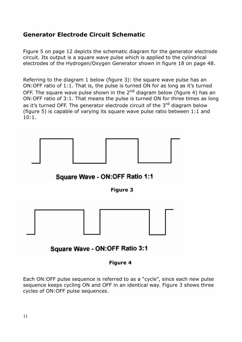
Figure 5 on page 12 depicts the schematic diagram for the generator electrode circuit. Its output is a square wave pulse which is applied to the cylindrical electrodes of the Hydrogen/Oxygen Generator shown in figure 18 on page 48.
Referring to the diagram 1 below (figure 3): the square wave pulse has an ON:OFF ratio of 1:1. That is, the pulse is turned ON for as long as it’s turned OFF. The square wave pulse shown in the 2nd diagram below (figure 4) has an ON:OFF ratio of 3:1. That means the pulse is turned ON for three times as long as it’s turned OFF. The generator electrode circuit of the 3rd diagram below (figure 5) is capable of varying its square wave pulse ratio between 1:1 and 10:1.
Figure 3
Figure 4
Each ON:OFF pulse sequence is referred to as a “cycle”, since each new pulse sequence keeps cycling ON and OFF in an identical way. Figure 3 shows three cycles of ON:OFF pulse sequences.
11
Figure 5
12
If these cycles were all to occur within a time span of one second, we would refer to the pulse as having a frequency of 3 cycles per second. If 127 cycles were all to occur within a time span of one second, we would refer to the pulse as having a frequency of 127 cps ( cycles per minute ). Signal frequencies used to be referred to in exactly that manner ( 3 cps, 127 cps, etc.) However, because some people love to change things, the terms we would use today would be 3 Hz and 127 Hz. Hz is used to honour Mr.Hertz, a scientist who helped pioneer the theories and practical uses of electronic signals. The symbol “K” is used to denote units of 1,000. Thus 3,000 Hz would be 3 KHz, and 127,000 Hz would be 127KHz. The square wave created by the circuit in diagram 3 can be varied in frequency from approximately 8 KHz to 260KHz.
The square wave pulse ratio determines the amount of current sent to the generator electrodes by the circuit of figure 5. If the ratio is low, such as 1:1, very little current arrives at the electrodes and the generator produces maximum gas volume. Varying voltage input from a potentiometer connected via a 10K resistor to pin 3 of component LM741 causes the circuit to vary the pulse ratio and therefore controls the amount of gases produced. The potentiometer shaft connects to the vehicle throttle linkage, enabling control of gas volume in direct response to voltage changes correlating with rotation of the potentiometer shaft in relation to throttle positioning. A trimming potentiometer connects pins 2 and 6 of component LM741, enabling precise adjustment of the throttle input signal. A second trimming potentiometer connects pints 4 and 7 of component NE555, enabling precise pulse width adjustment.
The electrode pairs of each generator exhibit a unique frequency of electrical resonance at which optimum gas volume is created. This frequency often varies considerably among different generators. Several factors determine resonance frequency such as: electrode size and shape, generator chamber size and shape, spacing between electrodes, coil parameters and relative positioning, and pulse amplitude(voltage level). A trimming potentiometer connected between pins 1 and 2 of component CD4069 allows the precise frequency to be obtained. By selecting various combinations of dipswitch connections to a bank of four capacitors, pulse frequency can be varied between approximately 8 KHz and 260 KHz.
Generator Coil Circuit Schematic
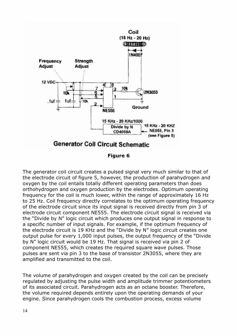
The diagram below(figure 6) depicts the schematic diagram for the generator coil circuit. Its output is a square wave pulse which is applied to the coil of the Hydrogen/Oxygen generator. (Can be seen on page 48)
13
Figure 6
The generator coil circuit creates a pulsed signal very much similar to that of the electrode circuit of figure 5, however, the production of parahydrogen and oxygen by the coil entails totally different operating parameters than does orthohydrogen and oxygen production by the electrodes. Optimum operating frequency for the coil is much lower, within the range of approximately 16 Hz to 25 Hz. Coil frequency directly correlates to the optimum operating frequency of the electrode circuit since its input signal is received directly from pin 3 of electrode circuit component NE555. The electrode circuit signal is received via the “Divide by N” logic circuit which produces one output signal in response to a specific number of input signals. For example, if the optimum frequency of the electrode circuit is 19 KHz and the “Divide by N” logic circuit creates one output pulse for every 1,000 input pulses, the output frequency of the “Divide by N” logic circuit would be 19 Hz. That signal is received via pin 2 of component NE555, which creates the required square wave pulses. Those pulses are sent via pin 3 to the base of transistor 2N3055, where they are amplified and transmitted to the coil.
The volume of parahydrogen and oxygen created by the coil can be precisely regulated by adjusting the pulse width and amplitude trimmer potentiometers of its associated circuit. Parahydrogen acts as an octane booster. Therefore, the volume required depends entirely upon the operating demands of your engine. Since parahydrogen cools the combustion process, excess volume
14
tends to reduce engine efficiency. With that in mind, the coil circuit should be adjusted such that only enough parahydrogen is created to prevent engine precombustion. However, if engine operating temperature is running on the high side(as determined by the CHT gauge), increasing parahydrogen volume is an effective way to lower the temperature.
In-Dash Indicators Circuit Schematic
The in-dash indicators circuit schematic is depicted by the diagram below(figure 7). Two gauges and four light emitting diodes (LED’s) Comprise the In-Dash indicators assembly. The generator pressure gauge connects via a hose to its respective fitting on the generator itself(Refer to figure 13 on page 34). The cylinder head temperature gauge electrically connects to a censor placed under an engine spark plug.
When the generator water level sensor is activated by low water level, its 12 VDC signal is sent to pin 2 of detector LM741 via a 10K resistor. Detector output from pin 6 triggers the base of power transistor E3055T, completing the circuit to activate the water pump and illuminate the “pump on” LED. The 12 VDC sensor signal also illuminates the “Gen Water Low” LED. When generator water rises to its normal level, the level sensor opens, turning off the pump and both LED’s.
When the tank water level sensor is activated by low water level (at 1/3 tank level), its 12VDC output signal illuminates the “WATER LOW” LED. After refuelling water, the level sensor opens, turning off the LED.
15
Figure 7
When the system is turned on, the “PWR ON” LED illuminates. The generator electrode circuit then activates the LED. If there is a problem, you will know if the LED fails to illuminate. This indicates an electrode circuit malfunction.
16
So Lets Build The System!
Since engine requirements dictate the volume of hydrogen and oxygen gases that the generator must create, and gas volume is variable, I recommend sizing it as large as is practical to allow reserve capacity. Maximum outside diameter of 4.5” is already determined by the construction material used for the generator housing.: 4” CPVC schedule 80 pipe. It is recommended to use a minimum height of 10”. Maximum height depends on available space within the engine compartment but, for structural integrity, limit height to 18”. Carefully check the engine compartment of your vehicle to ensure that adequate space exists for generator installation. If adequate space does not exist either limit the generator height, or locate the generator within the trunk, or as far forward as possible underneath the dashboard.
CAUTION:
It may be possible to obtain 3-1/2” outside diameter stainless steel tubing with a wall thickness of .040” to .063” and T304 alloy at a local shop that manufacturers exhaust or muffler systems. All tube dimensions, including roundness, must be held within .005” throughout its entire length. Do not use cheap tubing. If you do, the efficiency of the system will be severely degraded. If you are unable to obtain high quality tubing locally, the following source is recommended:
Eagle Stainless
Tube & fabricating, INC
10 Discovery Way
Franklin, MA 02038
Phone: 1-800-528-8650
Local phone:508-528-8650
1. After determining generator height, obtain a 3-1/2” outside diameter stainless steel tube with wall thickness of .040” to .063” and length 5” shorter than the determined height of the generator. A standard alloy of T-304 stainless steel is recommended for the electrodes. This tube will be used to construct the outer electrode.
Note:
17
The following steps: 2 through to 4 will be used to determined the outside diameter for the inner electrode. This procedure will create a .045” gap between the inside wall of the outer electrode and the outside wall of the inner electrode. This value is an ideal gap for maximum and most efficient production of hydrogen and oxygen gases with the system.
2. Multiply the wall thickness of the outer electrode by a factor of 2 and record the result as dimension A. For example, if the wall thickness is .050”, dimension A would be .100”.
3. Add a value of .090” to the value of dimension A and record the result as dimension B. For example, if dimension A is .100”, dimension B would be .190”.
4. Subtract the value of recorded dimension B from 3.50”. Record this value as dimension C. For example, if dimension B is .190”, dimension C would be 3.31”.
Note: The caution above also applies to the inner electrode.
5. To construct the inner electrode, obtain a stainless steel tube with an outside diameter equal to the recorded dimension C, with wall thickness of .040” to .063”, T304 alloy, and length equal to that of the outer electrode.
6. Referring to the following diagram below: drill eight ¼” holes, spaced at 45 degree intervals, around the diameter of one end of the outer electrode tube. Locate the hole centers 11/32” from the tube edge, clamp a large diameter wood dowel or rod in a vice to back up the electrode while drilling. Deburr the holes after drilling.
Note:
For best results, drilling stainless steel requires a carbide-tipped drill bit and light lubricating oil. Take your time drilling so as not to overheat the electrode.
18
Figure 8
7. Repeat the procedure of step 6 to drill eight ¼” inch holes at the same distance from the end of the inner electrode tube.
8. Referring again to the diagram above:, drill 1/8” holes around the end of the outer electrode closest to the ¼” holes. Locate the hole centers 3/32” from the tube edge, with hole centers spaced at 3/8” intervals around the entire diameter. Deburr the holes after drilling.
9. Repeat the procedure of step 8 to drill 1/8” holes around the entire diameter of the end of the inner electrode. Deburr the holes after drilling. Thoroughly clean all oil residue from both electrodes using a soft clean cloth and MEK of acetone as a cleaning solvent.
Note:
Bare stainless steel welding rod, T304 alloy, can be obtained at any welding supply store.
19
10.Referring to the diagram above(figure 8 page 19), cut two 3” rod lengths from 3/32” diameter bare stainless steel welding rod, alloy T304. Using a file, square off and deburr the rod ends.
Note:
Silver-bearing solder and flux can be purchased at any large hardware of electrical supply store.
11.Referring to the diagram above(figure 8 on page 19), solder one of the rods to the outside surface of the outer electrode. Position the rod parallel to the length of the electrode with 2” protruding past the end of the tube. Use silver-bearing solder and flux appropriate for soldering stainless steel.
12.Repeat the procedure of step 11 to solder the other rod to the inside surface of the inner electrode.
13.After the electrodes have cooled, thoroughly scrub the solder joints with warm soapy water using a stiff-bristle brush. Thoroughly rinse the electrodes with warm water and dry with a soft clean cloth.
Housing
Caution:Use CPVC pipe (schedule 80) to construct the generator housing. Do not use PVC pipe, or CPVC schedule 40, since it will not withstand high temperature or pressure as well.
Caution: Do not use CPVC pipe of size greater than 4” since it does not offer an adequate safety margin against rupture when subjected to high pressure and temperature.
Caution: Careful attention to craftsmanship and detail during generator construction is essential to ensure safe and reliable operation.
NOTE: Any large plumbing supply or plastics supplier may be able to supply
20
CPVC schedule 80 pipe, fittings, and accessories required to construct the generator. A recommended supplier is United States Plastic Corporation as they have always provided friendly and dependable service over the years, they will stock everything you’ll ever need.
You can contact them on the following number: 1-800-537-9724
List of materials:
One CPVC 4” threaded pipe nipple, length 12”, schedule 80
One CPVC 4” pipe, length 12”, schedule 80(only needed to housing height exceeds 10”.
One CPVC 1-1/2” pipe, length 12”, schedule 80
Two CPVC 4” straight couplings, schedule 80 ( only needed if housing height will be 10” )
One CPVC 4” cap, schedule 80
One CPVC threaded cap, schedule 80
One 1/8” thick, 24” x 48”, CPVC sheet
One 1” diameter, 6” length. CPVC rod
One pint can of CPVC cement
One pint can of primer
One 8 ounce can of pipe joint compound
1. CPVC 4” schedule 80 pipe is used to construct the generator housing. Since one end of the pipe will require threading, purchasing a 12” threaded pipe nipple rather then a threading a pipe yourself is recommended. Refer to the Generator details view – figure 10 page 26.
21
Note: CPVC 4” Schedule 80 pipe has an outside diameter of 4.5”.
Note: If the height of the housing will be 10”, as determined during the procedure at the beginning of the “Electrodes” section on page 18, follow directions of step 2, then go to step 8. If the height will be greater than 10”, go to step 3.
2. Using a miter box, or table saw to assure squareness, cut off one of the 12” pipe nipple threaded ends 2-3/4” from the end. Dress the cut edges with sandpaper or a fine-tooth file. Go to step 8
3. Using a miter box or table saw to assure squareness, cut the threaded pipe nipple 5-1/2” from one of its threaded ends. Dress the cut edges with sandpaper or a fine-tooth round file.
Caution:
Read directions printed on the primer and cement can labels for proper use of the products. After priming, apply cement as soon as possible. To obtain safe and reliable bonding, do not let the primer dry before applying cement.
4. Prime the outside mating surface of the cut end of the 5-1/2” pipe nipple and one of the inside mating surfaces of the coupling. Apply an even layer of cement to the primed surface and assemble the parts. Allow the parts to air dry for at least 10 minutes before going to step 5.
5. Prime the outside mating surface of the 12” pipe and inside mating surface of the coupling attached to the pipe nipple. Apply an even layer of cement to the primed surfaces and assemble the parts. Allow the parts to air dry for at least 30 minutes before going to step 6.
6. If the height of the housing is to be 18”, go to step 8. If the height is to be less than 18”, go to step 7.
7. Using a miter box or table saw to assure squareness, cut the pipe assembly near the unthreaded end to form a total pipe length to equal to ½” less than the housing height. Dress the cut edges with sandpaper or a fine-tooth round file.
8. Measure the inside diameter of the threaded end cap. Securely clamp
22
1/8” thick CPVC sheet to a drill press bed. Drill a ½” diameter hole through the sheet. Using a fly cutter, cut a disk with the measured diameter. Check that the disk fits snugly into the end cap. If loose, replace with a slightly larger disk. If tight, replace with a slightly smaller disk. Be sure to drill a ½” hole first if a new disk is cut. Cut a second disk to the correct diameter with ½” center hole.
9. Apply primer, and then cement, to one surface of each disk and join the disks together. Align the disk edges and wipe excess cement from the edges. Allow the disks to air dry for an hour before going to step 10.
10.(Referring to figure 9 below)Bevel the edges of the disk to fit the curved contour of the bottom of the end cap. Be sure the outer edge of the disk measure between 1/32” and 1/16” after bevelling.
Caution: The electrodes will be attached to the contoured disk. Form the contour accurately to assure structural integrity of the system.
Figure 9
Caution: The end cap will be temporarily threaded onto the housing to assure accurate alignment of the disk. Do not use excessive cement when installing the disk to prevent bonding of the housing and end cap threads.
Caution: Be sure petroleum jelly coats only the end cap threads
23
11.Lightly coat the threads of the housing and end cap, and bottom edge of the housing, with petroleum jelly. Apply primer to the mating surfaces of the disk and end cap. Apply cement to the primed area of the end cap only and install the disk, seating it firmly and evenly. Remove any cement that oozes from between the parts with cotton swabs.
12.Temporarily thread the end cap onto the housing, seating it slowly, but firmly. Wait about 15 minutes for the cement to partially dry and then remove the end cap.
Caution:
Be sure to measure the inside diameter of the unthreaded end cap before cutting disks.
13.Repeat the procedure of the preceding steps 8 through 10 for the unthreaded end cap. There’s no need to apply petroleum jelly to any areas of the unthreaded end cap. Apply primer to the mating surfaces of the disk and end cap. Apply cement to the primed area of the end cap only and install the disk, seating it firmly and evenly. Remove any cement that oozes from between the parts with cotton swabs.
14.Seal the ½” hole in the threaded end cap disk with electrical tape. Using a stiff bristle brush and warm soapy water, thoroughly clean petroleum jelly from the threads and all other areas of the end cap and housing. Rinse all parts with warm water.
15.Repeat step 14, and then wipe the parts dry with a soft clean cloth.
16.Remove the electrical tape from the threaded end cap. Allow the end caps to air dry for at least 8 hours before going to step 17.
17.Completely cover the inside surfaces of both end caps with strips of electrical tape. Cut away tape to open up the ½” hole in each disk.
Note: The cavity in each end cap will be filled with epoxy cement. To prevent trapping air bubbles, the caps must remain level while the epoxy cures. Centering and levelling the curved caps on the inner cores of large rolls of tape works well.
Caution: Use only high quality, high temperature, and waterproof
24
epoxy cement to fill the end cap cavities. Using any other cement may lead to eventual failure of the system.
18.Purchase a high quality, high temperature, and waterproof epoxy cement to fill the end cap cavities. I highly recommend J-B WELD, which can be purchased at any large hardware or automotive store. It comes packaged in two 2-ounce tubes ( one tube resin and one tube hardener). You will probably need at least one package to fill each end cap. If you have any questions about J-B Weld, you can contact them here:
J-B Weld.
PO BOX 483
Sulphur Springs, TX 75483
Phone 1-903-885-7696
25
Figure 10
26
Note: All epoxy cements cure by chemical reaction ( after the hardener is mixed with resin) J-B Weld remains pliable for about 30 minutes. There’s no need to rush filing the end cap cavities, but be aware that once the cement is mixed, there’s no stopping it from curing. If you have to remove or adjust anything after it cures, you’ll need dynamite to get things apart.
Note: Be sure to mix equal amounts of resin and hardener ( if using J-B Weld) The resin and hardener are different colours, one black and one white to avoid confusion. When mixed properly, you end up with a nice dark grey cement. If you accidentally mix resin with resin, or hardener with hardener, you end up with nothing but a big mess.
19.Mix about 4-ounce batch of epoxy in a disposable container such as a small paper cup. Slowly fill the cavity ( to avoid trapping air bubbles) to the top of the ½” hole in one of the end caps. If necessary, mix more epoxy.
Note: Be sure you have enough epoxy on hand to totally fill the remaining cavity. If not, purchase more before you start. After epoxy cures, it has a very poor adhesion with newly mixed epoxy.
20.Repeat step 19 to fill the remaining end cap cavity.
21.Allow the epoxy to cure for at least 24 hours. Remove all electrical tape from the end caps. Remove any epoxy from above the top of the ½” hole until flush with the disk surface by grinding, scraping, sanding or doing whatever is required.
22.Measure the inside diameter of the inner electrode. RECORD THIS MEASURE AS DIMENSION D.
23.Securely clamp 1/8” thick CPVC sheet to a drill press bed. Using a fly cutter, cut a disk with diameter equal to dimension D from the sheet. Check that the disk slides easily into the end of the inner electrode opposite the soldered rod, being neither loose nor tight. If loose, replace with a slightly larger disk. If tight, replace with a slightly smaller disk.
24.Subtract the value of .250” from the recorded dimension D. Record this new value as dimension E. For example, if dimension D is 3.21”, dimension E would be 2.96”.
27
25.Securely clamp 1/8” thick CPVC sheet to the drill press bed, using a sly cutter, cut another disk with diameter equal to dimension E.
Caution: Read directions printed on the primer and cement can labels for proper use of the products. After priming, apply cement as soon as possible to obtain safe and reliable bonding, do not let the primer dry before applying cement.
26.Apply primer, and then cement, to one of the flat surfaces of each disk. Join the disks, centering the smaller disk on the larger disk.
Note: The procedure of steps 27 and 28 will be used to cut a flat ring from CPVC sheet. Do not unclamp the sheet from the drill press bed until step 28 has been completed.
27.Securely clamp 1/8” CPVC sheet to the drill press bed, centering the cutter at least 3” from any edge of the sheet. Cut a 3-1/2” hole in the sheet.
28.Adjust the cutter to cut a ring with an outside diameter of 3-15/16”/
29.Check that the ring slides easily onto the end of the outer electrode, opposite the soldered rod, being neither loose nor tight. If loose, replace with a slightly smaller inside diameter. If tight, replace with a ring slightly larger inside diameter.
30.Repeat the procedure of step 27 to cut a 3-5/8” hole into 1/8” thick CPVC sheet.
31.Repeat exactly the same procedure of step 28.
32.Apply primer, and then cement, to one of the flat surfaces of each ring. Join the rings, aligning the outer edges. Wipe any excess cement from the outer edges. Allow the rings to air dry for at least 30 minutes before going to step 33.
33.Grind a small notch into the inner edge of the rings, just large enough to allow the rings to clear the soldered rod and solder when slid onto the rod end of the outer electrode.
Note: The procedure of step 34 centers the rings within the threaded end cap. Be sure the wrapping tape does not protrude below the edge of the smaller ring at any point. Do not overlap tape ends if more tape is added – simply butt the tape ends before continuing to wrap.
34.Using plastic electrical tape, wrap the outer edges of the rings until they
28
slide easily into the threaded end cap. If the rings fit loosely, add more tape. If the rings fit tightly, remove tape.
Note: Refer to the following figure 11 for details related to installing the rings into the threaded end cap. Apply primer only to the flat surface of the threaded end cap contacted by the smaller ring. Do not remove the tape until instructed to do so.
35.Apply primer to the flat surface of the smaller ring. Using a cotton swab, apply primer to the flat surface of the threaded end cap contacted by the smaller ring. Apply a thin, even layer of cement to the primed surfaces and install the ring assembly into the end cap. Allow the parts to air dry before going to step 36.
Note: The procedure of step 36 centers the disks completed in step 26 within the threaded end cap. Be sure the wrapping tape does not protrude below the surface of the small disk at any points. Do not overlap tape ends if more tape is added- simply butt the tape ends before continuing to wrap. Refer to figure 11 above for details related to installing the disks into the threaded end cap.
36.Using plastic electrical tape, wrap the edge of the large disk until the tape creates a snug fit with the inside edge of the ring assembly.
29
Note: Be sure to align the disks with their notch offset at least ¾” from the ring notch, as shown in figure 11.
37.Apply primer to the flat surface of the small disk and the flat inside surface of the threaded end cap. Apply an even layer of cement to the primed surfaces and install the disk assembly into the end cap. Align the disks with their notch off set at least ¾” from the ring notch, as shown in figure 11. Using a large C-clamp, lightly clamp the disks and end cap. Allow the parts to air dry for at least 8 hours before going to step 38.
38.Remove all electrical tape from the threaded end cap assembly, scrape away any excess cement that may have oozed onto the flat inside surface of the end cap in those areas that will contact the bottom edges of the electrodes and threaded end of the housing.
39.Drill a 37/64” hole through the center of the threaded end cap as shown in figure 11.
Note: Threads will be tapped later into the hole drilled through the center of the end cap, to attach the drain cock.
Using a #41 bit, drill two holes through the bottom of the threaded end cap at the locations shown in figure 11.
40.Temporarily align each electrode and rod with its respective hole drilled in step 39. Check that each electrode and rod can be installed into the threaded end cap and seated firmly on the cap surface. Make adjustments as necessary to achieve correct seating of the electrodes.
Using a marking pen, mark a short reference line near the top inside of the inner electrode. Mark another short reference line near the top inside of the outer electrode, aligning it with the mark on the inner electrode. Remove the electrodes from the end cap.
Note: The procedure of step 41 centers the inner electrode within the outer electrode. Do not overlap tape ends if more tape is added, simply butt the tape ends before continuing to wrap.
41.Using plastic electrical tape, wrap the top end of the inner electrode until it fits snugly into the outer electrode. Allow about ¼” of the tape to protrude above the edge of the electrode to facilitate easy removal. Do not remove the tape until instructed to do so.
42.Arrange a way to solidly support the threaded end cap while installing
30
the electrodes and while the epoxy cures ( takes about 8 hours ). Centering and levelling the curved cap on the inner core of a large roll of tape works well.
43.Once again, clean the bottom ends of the electrodes with MEK or acetone using a soft clean cloth.
44.Seal the bottoms of the two holes in the end cap with short strips of electrical tape to prevent epoxy from dripping out. The tapes will be pushed aside as the electrode rods poke through, after which the tapes can be removed.
45.Mix up about a 2-ounce batch of epoxy in a disposable container such as a small paper cup. Fill the slot in the end cap ( where the electrodes are installed) all the way around to about its half-full level.
Note: Be sure to install the outer electrode first.
46.Using your finger, apply a very thin, but unbroken coat of epoxy, completely around the bottom edge ( rod end) of the outer electrode. Form a band extending about ¼” high from the bottom edge, coating both the inside and outside surfaces of the electrode.
Caution: The small holes around the bottom edges of the electrodes help secure the electrodes to the end cap because epoxy fills the holes. Install the electrodes slowly into the end cap slot so as not to trap air bubbles within the holes.
47.Install the outer electrode into the end cap. As the electrode starts to enter the slot, lower it very slowly so that the epoxy has sufficient time to flow into the small holes drilled around the bottom edge without trapping air bubbles. After the electrode is firmly seated onto the end cap surface, remove the tape from the bottom of the end cap.
48.Apply a thin film of petroleum jelly to the surface of the tape wrapped around the top of the inner electrode.
49.Repeat the procedures of step 46 through 48 to install the inner electrode into the end cap. Use the alignment marks on the tops of the electrodes as an aid in locating the rod hole in the end cap.
50.Place about five pounds of weight on top of the electrodes to help keep them firmly seated against the end cap. Folding a towel or two into several folds and placing them on top of the electrodes, with a stack of hardcover books on top, works well. That method distributes the weight evenly, which can otherwise be difficult because of the tape protruding from the top of the inner electrode.
31
51.Using cotton swabs, remove any excess epoxy oozing from the eight 1/4” holes around the bottoms of the electrodes. If necessary, continue to do this until the epoxy begins to thicken ( in about 30-45 minutes). Using household tissues or disposable rags, clean epoxy from the rod ends protruding through the end cap, and from the surrounding surface of the end cap.
Caution: Allow the epoxy to cure for at least 24 hours at temperatures of 70 degrees or higher before removing the electrode weights or otherwise disturbing the electrode assembly. For lower temperatures, allow even longer cure time.
52.Remove the weights from the electrode assembly after the epoxy has cured for at least 24 hours, and remove the tape from the inner electrode.
Using #400 grit (or finer) sandpaper, remove epoxy residue from the rod ends protruding through the bottom of the threaded end cap.
Housing Attachments:
1. Temporarily thread the electrode assembly onto the generator housing, tightening it firmly. Support the entire assembly on the inner core of a large roll of tape as was done in the preceding step 42.
2. Referring to figure 12 below, fabricate 3 coil support brackets ( with the indicated dimensions) from 1/8” thick CPVC sheet.
Note: For most efficient operation, the coil must be located approximately 1/4" above the tops of the electrodes. A shim is placed between the electrodes and each bracket to achieve correct clearance. Exercise care to avoid cementing shims to the brackets.
3. Use scrap pieces of 1/8” thick CPVC sheet as shims between the tops of the electrodes and the brackets. Apply primer, and then cement, to the brackets and the inside wall of the housing at 120 degree intervals as shown in figure 11. Attach the brackets and allow cement to air dry for at least 30 minutes before going to step 4.
32
4. Remove the electrode assembly from the housing.
Note: Bracket arrangements for mounting the generator are dictated by the requirements of each system installation. Figure 13 below (on page 34) shows one of the simplest and most commonly used arrangements. Other arrangements can be easily constructed with 1/8” CPVC sheet.
Note: Brackets 1/4” thick are constructed from two layers of 1/8” thick CPVC sheet.
5. Cut four 1-1/2” x 6” mounting bracket strips from 1/8” thick CPVC sheet, as shown in figure 13 below(on page 34). Dress the edges of each strip using sandpaper or a fine-tooth file. Form each of the two brackets by applying primer, and then cement, to the mating surfaces of each of two strips and joining them together. Align the edges of each strip and wipe excess cement from the edges.
Note: Material from a ring cut from the straight coupling will be used to make part of the generator housing brackets. It will also be used to make a doubler to increase wall thickness of the housing where a hose fitting is installed.
6. Cut a 1-1/2” wide ring from the end of the coupling. Referring to figure 14 below, and using a band sander, sand the side of the ring to form a flat surface approximately 1-1/4” wide. Sand the side of the ring at
33
another point to form a similar surface. Cut each of two flat surface sections from the ring by cutting at both ends of each flat surface. As shown in figure 14 below(page 36), this will form two sections from the ring, each with flat outside surfaces 1-1/2” by approximately 1-1/4”. Dress the edges of each section and round the corners slightly using sandpaper or a fine-tooth file.
7. As shown in figure 14(page 36), attach a pipe section to each of the two brackets at their midpoints, applying primer to the flat surface of each section and its mating surface on the bracket, and then applying cement. Be sure to square the curved surface of each section with the length of the bracket.
8. Make a doubler by cutting a section 1-1/2” wide from the ring as shown in figure 14. Dress the edges and round the corners slightly using sandpaper or a fine-tooth file.
Temporarily thread the end cap onto the housing, seating it firmly. Choose a point anywhere around the housing as shown in figure 14, and mark a spot ¼” up from the edge of the end cap. Remove the end cap. Apply primer, and then cement, to the mating surfaces of the doubler and housing and attach the doubler to the housing with its lower edge at the market spot. Align the edge parallel to the housing bottom edge. Allow the cement to air dry for at least 8 hours before going to step 9.
34
9. Drill a 37/64” hole through the center of the 1-1/2” x 1-1/2” doubler and housing wall shown in figure 14 below(page 36). Be sure to keep the hole square with the housing wall.
Note: Threads will later be tapped into the hole to install a barbed hose fitting to connect the check valve.
10.Drill a 1/4” fastener hole near the end of each bracket ( total of 4 holes) at the locations shown in figure 13. Slightly round the corners of each bracket using sandpaper or a fine-tooth file.
Note: The check valve hose attaches to a barbed fitting to be installed later into the hole drilled in step 9. Determine the direction in which you prefer the fitting point directly left ( as shown in figure 13 ) or directly right to minimize generator space requirements.
11.Position the brackets as shown in figure 13, and clamp them to a flat surface. Check that the housing seats evenly into the curved section of each bracket with no gaps between the housing and curved section. If necessary, loosen the clamps to reposition the brackets.
Apply primer, and then cement, to the mating surfaces of the brackets and housing. Attach the housing to the brackets. Place supporting blocks on each side of the housing to keep it from rotating or shifting during assembly. Wait at least 8 hours before loosening the clamps and moving the housing assembly.
35
Unthreaded end cap:
List of materials:
-Thread taps, 1/8” NPTF and 3/8” NPTF ( cutting tool supply:specify Greenfield taps from CPVC pipe, or obtain locally)
- Two 1/8” NPT x 1/8” barbed hose fittings ( SMC part #: 253490)
- Two 3/8” NPT stainless steel inline check vales ( Generant part #: ICV-MM-375-SS-1)
- One 3/8” NPT pressure relief valve ( stra-val part #: RVA-05, 3/8” NPT, specify pressure setting of 85 psi)
List of materials: (continued)
-One 3/8” NPT internal seat drain cock ( fastener hut part #: 230a)
- Five 3/8” PTF 3/8” brass barb hose fittings, male pipe rigid (PTF short) (fastener hut part#: 10506b-106a)
-Four 3/8” NPTF x 3/8” brass barb hose fittings, female pipe rigid (fastener hut
36
part #:10506b-206a)
-One 35 ss series stainless steel top mount level switch, 1/8” NPT ( norgen part #: 0107-024)
-One LS 11 plastic side mount level switch, PBT, 5/8” – 11 UNC ( norgren part #: 1873-024)
Note: A short length of CPVC rod inside the end cap will be used as a spacer for the water level switch.
1. Using a miter box or table saw to assure squareness, cut a spacer approximately 2” long from 1” diameter CPVC rod. Using an “R” size drill bit, drill a hole through the center of the rod its entire length, and parallel to its length. Also drill a hole through the center of the end cap with the “R” drill, as shown in figure 15(page 38 below).
Caution: Be sure to use only NPTF taps. To prevent possible water and gas leakage, do not use NPT taps. Both NPT and NPTF threads will seal properly in NPTF tapped holes.
38
Caution: Be sure to tap to the correct depth by turning the tap until the 12th thread from the front of the tap fully enters the hole.
Caution: Be sure to always keep the tap aligned parallel to the sides of the spacer.
2. Using a 1/8-27 tap, tap threads into one end of the hole drilled in the spacer. Be sure to keep the tap aligned parallel to the sides of the spacer and to tap to the correct depth of 12 threads from the end of the tap.
3. Temporarily thread the 35ss water level switch into the tapped hole, seating it firmly. Insert the switch power leads from inside the end cap through the drilled hole. Measure and record the distance from the inside surface of the end cap to the end of the switch center tube.
Remove the switch from the rod, making a square cut, shorten the rod as required so that the end of the switch center tube is positioned 3” from the surface of the end cap, as shown in figure 15.
4. Apply primer, and then cement, to the untapped end of the spacer and its mating surface inside the end cap. Install the spacer, being certain to align the holes in the spacer and end cap. Using a cotton swab, remove any excess glue that may have oozed into the hole.
Slosh Shield
1. Using a miter box or table saw to assure squareness, cut a 3-1/16” long section from 1-1/2” CVPC pipe. Drill four (4) 1/8” holes into the sides of the pipe, spaced at 90 degree intervals and 1/4” from the edge as shown in figure 16 below.
Note: Six of the seven disks cut will be used for the flame arrestor.
2. Using a fly cutter, cut seven (7) 1-57/64” disk from 1/8” thick CPVC sheet. Drill a 3/8” diameter hole through the center of one of the disks.
3. Apply primer, and then cement, to the mating surfaces of the drilled disk and the end of the pipe opposite the four holes. Attach the disk to the pipe, being sure to center the disk on the pipe.
39
Flame Arrestor1. Using a miter box or table saw to assure squareness, cut a 3” long
section from 1-1/2” CVPC pipe.
2. Using a fly cutter, cut a 1-1/2” disk from 1/8” thick CPVC sheet. Check that the disk fits snugly inside the pipe cut in step 1.
If it doesn't fit snugly, adjust the cutter as required and cut a total of four (4) disks.
3. Apply primer, and then cement, to the surface of each of two disks and join the disks together. Align the disk edges and wipe excess glue from the edge of the joined disks. Repeat the procedure for the two remaining disks.
4. In the same manner as in step 3, make 2 stacks of 3 disks each from the six disks cut in step 2 of the slosh shield procedure. Allow the disks to air dry for at least an hour and then drill a 37/64” hole through the center of each of the two stacked disks.
5. Referring to the following figure 17 below, drill a total of thirteen (13) 1/8” holes through each of the two 1-1/2” disks at the indicated locations.
40
6. Apply primer to the edge of one of the 1-1/2” disks and about 3/8” into either end of the 3” pipe bore. Apply cement to the primed surfaces and slide the disk 1/4” into the pipe bore, creating a 1/8” gap between the disk and the pipe end as shown in figure 17 above. Form a small fillet of cement around the outer junction of the disk and pipe bore. Stand the pipe on end for 5 or 10 minutes ( until the cement won't run) to prevent plugging the holes with cement. If any hole is plugged, use a short length of stainless steel rod to open it back up. Allow the cement to air dry for about an hour before going to step 7.
7.Pack the inside of the flash arrestor with coarse stainless steel wool. Repeat the procedure of step 6 to install the remaining 1-1/2” disk.
Note: Stainless steel wool is available at some large supermarkets, or you can purchase it from the following source:
IWP
2575 W Lemoyne
Melrose Park, IL 60160
Toll Free: 1-800-732-9336
Fax: 1-708-345-0810
Caution: Be sure to use only NPTF taps. To prevent possible water and
41
gas leakage, do not use NPT taps. Both NPT and NPTF threads will seal properly in NPTF tapped holes.
Caution: Be sure to tap to the correct depth by turning the tap until the 12th thread from the front of the tap fully enters the hole.
Caution: Be sure to always keep the tap aligned squarely with the surface around the drilled hole.
Note: Be sure the two stacks of three disks joined in the preceding step 4 have air dried for at least 24 hours.
Note: When drilling holes in the following step 8, be sure to keep the drill bits squared with the curved outer surface of the unthreaded end cap. This places the axis of each of the three holes at an angle to the axis of the center hole as shown in figure 15 on page 38.
8. Referring to figure 15 on page 38, drill two 37/64” holes through the top of the unthreaded end cap, each located 1-3/4” from the center hole in the cap. Be sure to keep the drill bit squared from the curved outer surface of the end cap.
Using an “R” size bit, drill a hole through the top of the end cap 1-3/4” from the center hole in the cap as shown on figure 15.
Note: Be sure to keep the taps aligned squarely with the surface around the holes. Tap to the correct depth of 12 threads from the end of each tap.
9. Tap 3/8-18 threads into the 37/64” holes at the following locations:
– Two holes on top of the unthreaded end cap.
– One hole on bottom of threaded end cap.
– One hole in doubler on housing wall.
– One hole in each of two flame arrestor end caps.
Tap 1/8-27 threads into an “R” size hole closest to the edge on top of the unthreaded end cap.
42
10.Using a 3/8-18 tap, tap threads into the 37/64” hole in each of the two stacks of three disks joined in the preceding step 4. Apply primer, and then cement, to the mating surfaces of one of the stacks of disks and the 3” flame arrestor pipe. Attach the disks to the pipe, being sure the tapped end of the hole faces outward. Repeat the procedure for the remaining stack of disks.
Water Level Switch Test
Note: it is important to verify correct operation of the water level switch before installing its slosh shield.
Caution: Never attempt to control power to any electrical device directly through the water level switch. Doing so will damage or destroy the switch.
Note: The water level switch contains very high quality magnetic reed contacts. It will reliably operate through millions of cycles when connected to a properly designed electronic circuit.
Note: The water level switch is usually supplied with NC ( normally closed ) contact configuration. Step 1 verifies the NC configuration.
1. Connect ohmmeter leads to the switch power leads. Suspend the switch from its power leads and verify that the ohmmeter indicates closed switch contacts. If the contacts are not closed. Go to step 3.
2. Slowly slide the switch float upward. Verify that its contacts open at approximately the midpoint of float travel. If the contracts open properly, go to step 4. If the contacts do not open properly, the switch is defective and must be replaced.
3. Using a marking pen, mark a small dot on top of the switch float.
Note: The switch probably has no (normally open) contact configuration. Inverting the float changes it to the required NC configuration.
Carefully remove the float retaining clip located at the bottom of the center tube. Remove the float, invert it and reinstall. Reinstall the retaining clip. Verify that the dot on the float is now at the bottom and repeat the procedure of the preceding steps 1 and 2.
43
4. Using a countersink tool, or large drill bit, form a small bevel in the outer end of the center hole in the unthreaded end cap through which the switch leads pass.
Note: As an added precaution against possible water and/or gas leakage, I recommend using pipe joint compound on all threaded generator housing components.
Caution: Do not apply excessive torque to the water level switch threads while installing the switch into its mounting spacer. Excessive torque can damage the spacer threads, causing water and/or gas leakage and possible system failure.
5. Apply a light coating of pipe joint compound to the threads of the switch and mounting spacer according to directions on the product label. Insert the switch power leads through the spacer hole and thread the switch into place, seating it firmly.
Note: The following steps are used to verify correct switch operation in response to water level changes.
6. Obtain a transparent container (such as a large glass jar) with an outside diameter of approximately 2-1/2” to 3-3/4” and inside depth of at least 3-1/2”.
Place the unthreaded end cap on top of the container with the switch inside. Be sure the bottom surface of the end cap seats evenly on top of the container. Position the end cap so that at least one of the large tapped holes projects inside the container and the switch float is at least 1/4” away from the container wall.
Note: Measure water level with the switch float in water.
7. Connect the ohmmeter leads to the switch leads. Check that the switch contacts are closed. Very slowly pour water through the large tapped hole until the switch contacts just open, and remain open. If the contacts close again, add a slightly amount of water and wait several seconds before checking again. Keep repeating this process until the switch remains open. Check that the water level is at least 2” from the top edge of the jar. If the water level is less than 2” from the top, the switch is defective and must be replaced.
8. Remove the end cap assembly from the jar and dry as necessary with a
44
soft clean cloth.9. Apply primer, and then cement, to the mating surfaces of the slosh shield
and end cap. Attach the slosh shield, centering it around the switch float.
Toroid Coil
List of materials:
– One Ferrite Toroid Coil Core, 3.50 OD x 2.00 ID x .500 Thick ( National Magnetics Part #: 995)
– Copper Magnet Wire, Teflon coated, Heavy Build, 23 AWG, 550 Ft ( MWS Wire Industries, must be custom ordered)
– One Package Heat Shrink Tubing, Assorted Sizes ( Radio Shack, Catalog #: 278-1610)
Material Sources:
National Magnetics Group
1210 Win Dr
Bethlehem, PA 18017-7061
Phone: 1-610-867-7600
Fax: 1-610-867-0200
MWS Wire Industries
31200 Cedar Valley Dr
Westlake Village, CA 91362
Phone: 1-818-991-8553
Fax: 1-818-706-0911
Acton Technologies
100 Thompson St
PO Box 726
45
Pittston, PA 18640
Phone: 1-570-654-0612
Fax: 1-570-654-2810
Radio Shack (Nationwide Stores)
Note: The system coil is hand-wound around a ferrite toroid core with insulated, high temperature copper wire. Close attention to detail and craftsmanship is essential to building an efficient and reliable coil. There are literally millions of different coil configurations out there. It's a great area for experimenting since coil design is as much art as it is science. Believe it or not, there is actually an organization dedicated to the craft, the International Coil Winding Association, based in England.
Note: Be forewarned that winding any coil, especially a toroid coil, is a tedious affair, but I'll do my best to make the job as easy as possible. The coil is creates from 2,000 turns of insulated copper wire wrapped around a circular magnetically sensitive core. That means you have to drag each wire wrap through the toroid core just as many times.
Note: Teflon insulated copper magnet wire is the only way to go. It handles heat extremes very well and is impervious to just about anything you can throw at it. It isn't cheap, but it's well worth the investment.
Customer order it from the MWS wire industries. They carry over 25,000 different magnet and speciality application wires. Be sure to order “double build” (extra heavy) insulation, 23 AWG. You'll need about 500 to 550 feet, so it's probably best to order 550 feet.
After the coil is completed, it should be coated with a few thin layers of CPVC cement, that way you end up with something that will last forever, it is practically bombproof, and is easy to solidly attach inside the housing with CPVC cement. But, getting anything to stick with teflon takes special chemical etching, that's why teflon cookware is so popular. It is commerically done by etching with some pretty nasty stuff. Several companies specialize in the process, but you don't want to know the cost. A safe and easy etching process that can be done at home, yet gives great results has recently been developed using a product called FluoroEtch. You simply warm FluoroEtch to about 130 degrees, slosh the coil around in it for about a minute, slosh in isopropyl or methyl alcohol ( sadly, the kinds you can't drink) for a minute or so, wash in warm soapy water, rinse with warm water, and let it air dry. After doing that, just about anything will stick to the Teflon coated coil wire. I'm telling you all
46
this so that when you call the people at Acton Technologies, you'll sound knowledgeable enough that they won't hesitate to sell you FluoroEtch :)
1. I recommend cutting the magnet wire into four (4) 100' lengths and one (1) 150' length. Otherwise, you have to drag 550' of wire through the core 2,000 times. Using math, that works out to just over 104 miles of wire dragging, average over 550 feet, or one sore arm and a tangled mess! By working with 100' and 150' lengths, you have to make four solder splices to the wire, but you cut your wire dragging down to less than 22 miles. You could even go with eleven (11) 50' lengths, cutting it to 9-1/2 miles and 10 solder splices. Or, carried to the extreme, 550 one foot lengths cuts it to less than ¼ mile ( 1,001 feet), but you have to make 549 solder splices!
Don't try short-cutting things by wrapping the wire around the core several times and pulling the rest of the wire on through. The continual bending and straightening will destroy the wire long before you reach its end. A modified version of that method works, but takes a decent amount of skill and experience to master.
Form a 3.5” OD X 2” ID X .50” Toroid Coil, from 23 AWG wire requires about 250 turns of wire per wrapped layer. Since the coil builds in size as it's wrapped, each wrap uses an average of about 3” of wire. So, each 100' wire provides about 400 wraps, or slightly over 1-1/2 layers, therefore, four (4) 100 foot lengths and one (1) 150 foot length will build an 8 layer coil of at least 2,000 turns.
Note: Save the 150' wire for the last layer in case you need extra wire to complete the 8th layer without splicing near the coil entry wire. Any time you interrupt wrapping, be sure to tightly wrap a strip of plastic electrical tape completely around the coil to secure the last wrap. Teflon is extremely slippery stuff, you don't want to come back only to find that all your coil wraps are loose. It will happen if you don't use tape.
Note: The first complete wrapping of the entire coil diameter forms layer #1 for the inner core. This is the only critical layer since each subsequent layer will automatically position itself by nesting between the wires of the previous wrap.
47
Figure 18
2. Referring to figure 19 below(page 49), slip a 1” length of small heat shrink tubing about 4” onto the magnet wire and apply heat to shrink it in place. If you are right-handed, you'll probably choose to wrap the coil in a clockwise direction, holding the core with your left hand. In that case, lay the shrink tubing on top of the core, angled off to the left at about 30 degrees from straight out as shown. Start the first wire wrap over the tubing at about its midpoint. This will be the start of layer #1 for the inner core. Be sure to keep the wire wraps tight against each other on the inside edge of the core, with no overlapping. Keep tension on the wire, with the wire always pointing straight out from the core. Precise wire positioning has little to no effect on overall coil performance but, the first wrap dictates the wire positions of each subsequent wrap since each wire will fall into the depression formed between the two wires of the preceding wrap. In short, if you do a sloppy job on the first layer, you will end up with a sloppy coil. So, take your time and do the job correctly. Continue wrapping until you have completed a full turn (completing coil inner layer #1). Tightly wrap a strip of plastic electrical tape around the wire and the coil entry wire at the end of layer #1.
48
3. Check the position of each wire on the outside edge of the core. If wrapped perfectly ( which of course, is impossible) there will be a .019” gap between any two wires. But, you can position each wire close enough by using a short piece of coil wire as a feeler gauge. If the feeler gauge wire touches the core surface between any two wires, the gap is too wide, so at least one of the wires is out of position. Using your fingernail, or other blunt-ended instruments that don't damage the wires, slightly shift wires to close the gap enough to keep the feeler gauge from contacting the core surface. Any gap that is too wide indicates an adjacent gap is to narrow, so those wires should be moved further apart. After going around the coil a few times, you will also be able to visually detect wires out of position.
4. Mix about a 1/2-ounce batch of epoxy ( such as J-B WELD). Using a small brush, carefully apply a thin layer of epoxy around the outer edge of the coil. Apply with a motion parallel to the wires to prevent wire movement, being sure the epoxy contacts the coil surface between wires. Suspend the coil from its wires and allow the epoxy to cure for at least 8hours before going to step 5.
Note: While wrapping coil layer #2 , be sure to count and record the number of turns.
5. Start wrapping coil layer #2, exercising care to position each wire into the gap formed between the wires of layer #1 on the inner and outer edges of the coil. Count and record the number of turns.
49
Continue wrapping until you get within about one foot of the wire end. Secure the wire by tightly wrapping plastic electrical tape around the wire and coil.
Note: Coil thickness tapers down between the inner and outer edges. To minimize inner coil thickness, position wire splices on the top or bottom of the coil, midway between the edges as shown on figure 19 above.
6. Temporarily wrap the wire for two or three more turns and cut it about 1/2” short of the outer edge. To splice to the next wire length, unwrap the wire and use a sharp knife to scrape the teflon coating from about 1/2” of each wire end. Always keep the knife blade perpendicular to the wire to prevent damage.
7. Slide a 1/2” length of heat shrink tubing over the end of the next length of coil wire. Be sure the tubing is large enough to fit over a wire splice. Twist the wire ends together for 7 or 8 turns to form a splice. Cut the splice to a length of about 1/4” and bend it back towards the coil until it lays flush against the coil wire. Solder the splice, slide the shrink tubing until it's centered over the splice, and apply heat to shrink the tubing. Wait a minute or two for the tubing and splice to cool and go on to step 8.
8. Remove the electrical tape from the coil and continue wrapping until layer #2 is completed. Record the total number of turns requires to complete layer #2.
Note: Although the total number of coil turns is not critical, almost all coils require a total of 8 wire layers.
9. Referring to the recorded number of coil turns needed to complete layer #2, determine the number of coil layers required to complete the coil with a total number of 1,800 to 2,100 turns.
Note: Be sure to end the last coil layer near the beginning of layer #1 Do not finish the coil with a partial last layer.
10.Repeat the procedure of the preceding steps 5 through 7 until the last layer has been completed. Be sure the last turn ends within a turn or two of the coil entry wire. Cut the last wire to a length of about 12”.
Note: Do not shrink the heat shrink tubing in step 11. It will be used only temporarily to secure the coil wires.
11.Referring to figure 19 above(page 49), temporarily slide a 5” length of heat shrink tubing over the ends of the coil wires. Draw the tubing snugly up against the outer coil edge and bend the coil leads back
50
towards the coil at the outer end of the tubing. Tightly wrap each coil wires 4 to 5 turns around the tubing, about 1” from the end, and twist the wires together for at least 5 or 6 turns.
Caution: Be very careful to prevent damaging the coil wires during the following following procedures.
Caution: To assure proper bonding of CPVC cement to the coil after etching, do not handle the coil with bare hands. If the coil must be handled, wear clean cotton gloves.
12.Using FluoroEtch, while suspending the coil by the heat shrink tubing, etch the surfaces of the teflon coated coil wires. Closely follow the directions on the product label. If necessary as an aid to etching, refer to the general description of the etching procedure, you can find that a few pages up. Always handle the coil by suspending it from the tubing during each phase, from etching through final warm water rinse. Use clean paper towels to absorb water drips from the bottom of the coil until dripping stops. Allow the coil to air dry for at least 4 to 5 hours before going to step 13.
13.Using a soft bristle brush, coat the entire surface of the coil with a thin and even layer of CPVC cement. Use cotton swabs to wipe away excess cement that may be dripping from the bottom of the coil until dripping stops. Allow the cement to air dry for at least an hour, then apply a second thin and even layer of CPVC cement in the same manner.
14.Repeat the procedure of the procedure of the preceding step 13 until a total of 5 or 6 layers of CPVC cement have been applied to the coil, allowing at least one hour drying time between each layer. Allow the final layer of cement to air dry for at least 8 hours before going to step 15.
Caution: Exercise care not to pull the coil exit wire away from the coil while removing the heat shrink tubing.
15.Unwrap the coil wires from the heat shrink tubing and remove the tubing from the wires. Cut a 1” length of heat shrink tubing large enough to slip snugly over the coil wires and the shrink tubing of the coil entry wire. Draw the tubing tightly up against the coil outer edge and apply heat to shrink the tubing.
16.Using a soft bristle brush, apply a thin bead of CPVC cement about 1/4” wide around the coil end of the tubing and surface of the outer coil edge. Allow the cement to air dry for about an hour and then apply a second bead of cement over the first bead.
17.Suspend the coil from the end of its wires and allow it to air dry for at
51
least 24 hours before going on to step 18.
18.Cut the coil wires to a length of 3” from the coil.
Toroid Coil Installation
Note: I recommend locating the coil electrical connections on the side of the housing directly opposite the water pump inlet port. This location minimizes possible coil wire connector fatigue due to the effects of water turbulence at high pump pressure.
1. Using a #41 drill bit, drill two holes in the housing wall at the locations shown on figure 20.
2. Cut two (2) 4” lengths of 3/32” bare stainless steel welding rod. Create a 90 degree bend in one end of each rod to form a leg approximately 1-1/2” inches long, as shown on figure 20 below. Cut the other leg to a length of 3/4”. Using a file, square off the ends of each rod and deburr the edges.
3. Use a sharp knife to scrape the teflon coating from about 1/2” of each coil wire end. Always keep the knife blade perpendicular to the wire to prevent damage.
4. Wrap each coil wire end around the top of a 1-1/2” rod leg for at least 4 or 5 turns. Using silver bearing electrical solder, solder each wire to its rod leg. Trim away any excess wire. Form a wire strain relief at the leg bottom by wrapping heavy thread at least 2 or 3 turns around the leg and wire. Secure the thread with a knot placed on the outside of the rod bend.
52
5. Using a soft bristle brush and warm soapy water, clean the soldered areas of the rod and wire. Rinse with warm water and allow the thread to air dry for at least an hour before going to step 6.
6. Coat the entire length of the long rod leg with a thin even layer of CPVC cement. Allow the cement to dry for about 15 minutes and apply a second thin coat of CPVC cement. Allow the cement to air dry for about 15 minutes before going to step 7.
7. Temporarily install the coil on top of its three support brackets within the housing. Position the coil with the wires and rods pointing toward the holes drilled in the preceding step 1. Temporarily attach three small strips of electrical tape on top of the coil to mark the location of each support bracket.
8. Remove the coil from the housing and apply primer to the bottom of the coil at the three marked locations and the top surface of all three support brackets. Coat the top of each support bracket with a heavy layer of CPVC cement. Install the coil onto the support brackets, positioning it with the wires and rods pointing towards the two #41 drilled holes. If necessary, shift the coil slightly to center its outside edges within the housing. Allow the cemented rods and wires to air dry at least an hour before going to step 9.
53
Note: The two #41 holes in the inside housing wall must be countersunk to a depth sufficient to clear the radius of the inside bend of each rod, allowing the soldered leg of each rod to lay flush against the housing wall with the soldered leg pointing upward.
9. Remove the three tape strips from the top of the coil. Using a countersink tool or large drill bit, deburr the inside ends of the #41 holes. Insert the rod ends into the holes and check that the inside bend radius clears the edge of each hole. If not, countersink slightly deeper until the desired clearance is obtained.
10.Using #400 grit or finer sandpaper, polish the surface of the unsoldered leg of each rod. Mix a small quantity of epoxy such as J-B WELD. Apply a thin coat of epoxy to the unsoldered leg of each rod. Using a toothpick, or other precise tool, apply a thin coat of epoxy to the inside of each #41 hole.
11.Apply a heavy layer of CPVC cement to the soldered leg of one rod. Fully insert the rod into the #41 hole with the soldered leg pointing directly upward. Hole the rod in place for about 5 minutes until the cement dries sufficiently to hold it in place. While waiting for the cement to partially dry, clean epoxy from the rod end using a soft clean cloth and solvent such as MEK or acetone. Repeat this procedure for the remaining rod. Allow the epoxy to cure for about 8 hours before going to step 12.
Note: Several layers of CPVC cement are used to secure the coil to the housing brackets, rods and wires to the housing wall, and to seal the rods against possible gas and/or water leakage through the holes in the housing.
12.Arrange the coil wires so they contact the housing wall as much as possible. Lay the housing on its side and apply a thick layer of CPVC cement over the wires and soldered leg of each rod. Extend the cement layer around the hole where each rod enters the housing wall, forming about a 1/2” diameter puddle around each hole. Allow the cement to air dry for at least 15 minutes before going to step 13.
13.Stand the housing on end. Using a soft bristle brush, apply a thick layer of CPVC cement over and around the coil surface above where it contacts each of the three support brackets. Be sure the layer extends the width of each bracket. Allow the cement to air dry for at least 15 minutes before going to step 14.
14.Repeat the procedure of the preceding steps 12 and 13 at least 4 or 5 times to obtain the desired thick layer of cement. Allow the cement to air dry for at least an hour between successive layers.
15.After the epoxy has cured for at least 24 hours, use #400 grit or finer sandpaper to remove epoxy residue from the rod ends.
54
Unthreaded End Cap Installation
Note: Generator function and efficiency is not effected in any way by the rotational position of the unthreaded end cap.
1. Check that the mating surfaces of the end cap and top of the housing are clean and free of debris of any kind. Clean the mating surfaces if necessary using a soft clean cloth and mild solvent such as isopropyl alcohol.
2. After determining the desired position of the end cap, apply primer to the mating surfaces of the end cap and top of the generator housing. Apply a thin layer of CPVC cement to the primed areas and slide the parts together, seating them firmly.
3. Stand the housing on end to prevent the possibility of excess cement running into threaded holes in the end cap, allowing it to remain in that position for at least an hour while the cement air dries.
Generator Final Assembly
1. Cut the two rod ends protruding through the bottom of the threaded end cap to a length of 1/2”. Using a file, square the end of each rod and deburr the edges.
Note: As an added precaution against possible water and/or gas leakage, I recommend using pipe joint compound on all threaded generator housing components.
Caution: To prevent damage to threaded holes in CPVC material, do not apply excessive torque to components while installing. Thread damage can cause water and/or gas leakage, and possible system failure.
5. Apply a light coating of pipe joint compound to all threaded holes in the generator housing and end caps according to directions on the product label.
6. Apply a light coating of pipe joint compound to the threads of the drain cock. Thread the drain cock into the 37/64” threaded hole in the bottom of the threaded end cap, seating it firmly. Repeat this procedure to install the remaining components:
55
– One 3/8” Barbed Hose Fitting into 37/64” hole in housing doubler.
– One 3/8” Barbed Hose Fitting into 37/64” hole on top of housing.
– One 1/8” Barbed Hose Fitting into “R” size hole on top of housing.
– One Pressure Relief Valve into 37/64” hole on top of housing.
7. Using a toothpick, or similar precise tool, force a small quantity of Silicone Sealant ( RTV Cement) into the hole in the end cap through which the water level switch leads pass. Form a small and smooth fillet of sealant around the leads and end of the hole. Allow the sealant to cure for at least 24 hours before going to step 8.
8. Visually inspect all surfaces and components of the housing and end cap to verify their integrity. Correct possible defects as required.
9. Thoroughly flush the interior of the generator housing with warm tap water. Stand the housing on end and allow excess water to drain for at least 15 minutes. Using a soft clean cloth, dry the housing exterior and threads of the housing and end cap.
10.Apply a light coating of pipe joint compound to the housing and end cap threads. Thread the end cap onto the housing and tighten firmly.
In-Dash Indicator Panel Assembly
Note: Personal preference dictates the layout of panel gauges and LED indicators. During assembly, refer to figures 5,6 and 7 on pages 12,14 and 16 respectively.
List of materials:
– One cylinder head temperature(CHT) gauge kit, 2-1/16” Diameter, ( includes spark plug mounted thermocouple sensor) (Bus boys Part #: VDO-310901).
– One 2-Gauge Custom Console (Bus Boys Part #: VDO-1108720).
– One Pressure Gauge, 2-1/16” Diameter ( Auto Meter Products Model #: 2360).
– Two bulb and socket sets, 2 watt (Auto Meter Products Model #: 2357)
– Four LED Indicators: Two Green (Radio Shack Part #: 276-304), One Yellow ( Radio Shack Part #: 276-351), One Red, Blinking (Radio Shack Part #: 276-308).
– Three 55' Spools 18 Gauge Insulated, Stranded Hookup Wire (Radio Shack Part #: 278-1220)
56
– One 9-Position Male Interlocking Connector (Radio Shack Part #: 274-229).
– One 9-Position Female Interlocking Connector (Radio Shack Part #: 274-239)
– Two Packages Crimp-On Snap Connectors (Each: 5 male, 5 female) Radio Shack Part #: 64-3085 and 64-3086)
– One Package Assorted Ring Terminals ( Radio Shack Part #: 64-3032).
– One Package Assorted Grommets ( Radio Shack Part #: 64-3025).
– One 10' length 1/8” Silicone Braid Reinforced Tubing ( US Plastic Stock #: 54051).
– One Package Small Nylon Tie-Wraps (Local Hardware Store)
Material Sources:
Bus Boys, Inc
183 Lake Blvd East
Redding, CA 96003
Phone: 1-530-244-1616 Fax (7/24): 1-530-224-0933
Auto Meter Products Inc
413 W Elm St
Sycamore, IL 60178
Phone: 1-815-895-8141 Fax: 1-815-895-6786
Radio Shack (Nationwide Stores)
United States Plastic Corp
1390 Neubrecht Road
Lima, OH 45801-3196
Phone: 1-800-537-9724
Note: The quickest and easiest, and usually the most attractive method for mounting gauges and LED's is to use a prefabricated console attached to the top of the dash panel. Other methods may work just as well, but I'll recommend the VDO-1108720 Custom Console, which is molded from ABS
57
plastic and is both attractive and durable.
1. Temporarily mount the CHT and pressure gauges in the console. Referring to figure 2 on page 9, determine the best locations for the 4 LED's and place reference marks at those locations on the outside of the console. Drill a 7/32” hole at each location. To assure proper adhesion of silicone sealant to the console interior surface, roughen the surface immediately around the area of the drilled holes with sandpaper.
2. Temporarily disconnect the CHT gauge thermocouple lead and mount the gauge in the console. Apply a light coating of pipe joint compound to the 1/8-27 threads of the pressure gauge and 1/8-27 barbed hose fitting. Thread the fitting into the gauge and tighten firmly. Slip the 1/8” silicone tubing fully onto the barbed fitting and secure with two small stainless steel hose clamps. Firmly tighten the hose clamps and mount and pressure gauge in the console.
Note: The sorter of the two LED leads is always the anode (+) lead.
3. Identify the anode (+) lead of each LED and cut to a length of 1”. Cut four (4) 3-foot lengths of 18 gauge hookup wire and strip 1/2” of insulation from the end of each wire. Wrap the stripped end of each wire end around each anode lead and solder. Slide a 1-1/2” length of heat shrink tubing over each wire and flush against the LED and shrink the tubing.
4. Referring to figure 2 on page 9, identify the console location for each LED. Using masking tape, or other means of labelling, attach an identifying label to each anode wire.
– Green, PWR ON
– Green, PUMP ON
– Yellow, GEN WATER LOW
– Blinking Red, TANK WATER LOW
5. Cut two lengths of hookup wire to use as jumper wires between the bulbs and sockets for the gauges. Strip 1/2” of insulation from the ends of each wire. Solder a wire to one socket center connector. Slide a 1” length of heat shrink tubing onto the wire and as far as possible onto the socket base. Shrink the tubing. Cut a 3-foot length of hookup wire and strip 1/2” of insulation from one end. Twist the ends of the soldered jumper wire and 3-foot wire together. Slide a 1” length of heat shrink tubing onto the wires, and solder the wires to the other socket center connector. Slide the tubing as far as possible onto the socket base and shrink the tubing. Label the wire “Positive” (+).
58
6. Cut a 6” length of hookup wire. Repeat the procedure of step 5 to connect the 6” wire and jumper wire between the two socket base connectors. Strip 1/2” of insulation from the end of the 6” wire.
7. Cut the cathode lead of the green “PWR ON” LED to 1-1/2” long. Cut the cathode lead of the yellow “GEN WATER LOW” LED to 1” long. Cut an appropriate length of hookup wire to serve as a jumper wire between the cathodes of both LED's. Strip 1/2” of insulation from each end of the wire. Solder the jumper wire to the yellow LED cathode. Slide a 1-1/2” length of heat shrink tubing over the wire and flush against the LED and shrink the tubing.
Twist the stripped ends of the jumper wire and 6” wire of step 6 together. Slide a 1” length of tubing over the two wires and solder them to the green LED cathode. Slide the tubing flush against the LED and shrink the tubing. Cut a 3-foot length of hookup wire and strip 1/2” of insulation from one end. Solder the wire to the green LED cathode. Slide a 1-1/2” length of heat shrink tubing over the wire and as far as possible onto the LED lead and shrink the tubing. Label the wire as “Ground”.
Cut the cathode leads of the two remaining LED's to 1” long. Cut two (2) 3-foot lengths of hookup wire and strip 1/2” of insulation from the end of each wire. Solder the wires to the LED cathodes. Slide a 1-1/2” length of heat shrink tubing over each wire and flush against the LED and shrink the tubing. Label the green LED wire as “PUMP ON CATHODE” and the red LED wire as “TANK WATER LOW CATHODE.”
Note: Silicone sealant cures by chemical reaction with oxygen and water moisture in the air, which is why it's sometimes referred to as RTV (Room Temperature Vulcanizing) cement. Sealant cure time can be shortened considerably by placing a water-dampened cloth within the console interior and placing the console into a plastic grocery bag(don't seal the bag so that it's airtight). This method is very effective in dry climates.
8. Slide each LED into its correct mounting hole on the console. Slide one LED about 1/16” back from the interior surface of the console and apply a small amount of silicone sealant into the gap between the LED flange and the console surface. Slide the LED back into place and flush with the console surface. Apply a thick bead of sealant around the LED flange and about 1/4” onto the console surface. Repeat the same procedure for the three remaining LED's. Allow the sealant to cure for at least 24 hours before going to step 9.
9. Install the bulbs and sockets into the gauges. Draw the seven LED wires and bulb socket wire together a short distance from the LED's and secure the wire bundle with a tie-wrap. Tighten the tie-wrap and cut off its unused strap.
59
10.Drill and/or grind a hole to install a 5/8” ID grommet through the engine compartment firewall at an appropriate location for touring of HyTronics wires, thermocouple lead, and pressure gauge tube. Deburr the hole and install a 5/8” ID grommet. Insert the thermocouple lead through the grommet from the engine compartment side and reattach it to its CHT gauge terminal.
11.Permanently attach the console to the dash at the desired location. Secure the wires, thermocouple lead, and CHT tube bundle with a tie-wrap placed about every 6” along the length of the bundle. To prevent collapsing the pressure gauge tube, be sure not to over-tighten the tie-wraps.
12.Cut the ends of the eight wires to the same length and strip 1/4” of insulation from the end of each wire. Attach each wire to a seperate pin of the 9-Position Male Interlocking connector by crimping or soldering.
13.Remove a spark plug from the engine and plug the hole with a soft clean cloth. To assure good electrical contact for the thermocouple, polish the area contacted by the spark plug with #400 grit or finer sandpaper. Remove the cloth from the spark plug hole. Slip the thermocouple ring over the spark plug threads and reinstall the spark plug. Tighten the spark plug to its normal torque value.
Water Tank and Pump
List of materials:
– One Rectangular Polyethylene Tank, 16 gallon, 21” x 14” x 14”(US Plastic part #:8658).
– One High-Head Pump, 12 vdc, 75 psi (minimum) (Flojet)
– One Brass Bushing, 3/4” PTF Male x 3/8” PTF female(Fastener Hut part #: 3220X12X06A).
– One Package Crimp-on Butt Connectors' (Radio Shack part #: 64-3037).
Material Sources:
Radio Shack (Nationwide Stores).
Fastener Hut Inc – (Ordering information listed on previous pages)
60
Flojet Corporation
20 Icon
Foothill Ranch, CA 92610
Phone:1-949-859-4945
Toll-Free:1-800-235-6538
Fax:1-949-859-1153
Note: Water tank capacity is not critical, but should be at least 5 – 10 gallons. The recommended tank is sturdily constructed, holds 16 gallons, and is furnished with a 3/4” FPT outlet fitting.
1. Apply a thin film of pipe joint compound to the internal threads of the 3/4” x 3/8” bushing and threads of a 3/8” barbed hose fitting. Thread the fitting into the bushing and tighten firmly.
2. Apply a thin film of pipe joint compound to the external threads of the bushing and internal threads of the water tank fitting. Thread the bushing into the tank and tighten firmly.
Note: The water level switch can be installed at the midpoint of either side wall of the tank. Determine the desired location based on routing of electrical leads, trunk layout, etc. One switch lead will be grounded to the vehicle frame in the trunk area and the other lead will be connected to the HyTronics module.
3. Drill or cut a 5/8” hole in the side wall of the water tank at the midpoint of its length and 4” up from the bottom. Flush the tank with tap water to remove plastic shavings.
4. Remove the tank cap. Drill a 37/64” hole through the center of the cap and thread with a 3/8-18 tap. Flush the cap with tap water to remove plastic shavings. Thread a 3/8” barbed hose fitting into the tapped hole and seat firmly. Cut a 6” length of high-low temperature silicone tubing. Slip the tubing onto the fitting and secure with two stainless steel hose clamps. Tighten the clamps firmly.
Caution: Never attempt to control power to any electrical device directly through the water level switch. Doing so will damage or destroy the switch.
Note: The water level switch contains very high quality magnetic reed contacts. It will reliably operate through millions of cycles when connected to an LED.
61
5. Strip 1/4” of insulation from the ends of the water level switch leads. Connect ohmmeter leads to the switch leads. Pivot the switch float until flush against the switch body. Verify that the ohmmeter indicates closed switch contacts. If the contacts are not closed, the switch is defective and must be replaced.
6. Pivot the float switch away from the body until it is within 10 degrees of its stop. Verify that the switch contacts are open. If the contacts are not open, the switch is defective and must be replaced.
7. Using a soft clean cloth, dry the tank side wall around the 5/8” hole. Apply pipe joint compound to the threads of the switch body and mounting nut, and their mating surfaces with the tank wall. Install the switch into the tank so the float pivots upward, aligning its pivoting axis parallel to the tank bottom. Firmly tighten the switch mounting nut.
8. Attach ohmmeter leads to the switch leads and verify the switch contacts are closed. Plug the tank outlet fitting and fill the tank with water until the switch contacts open. Continue filling the tank until the water level rises an additional 2”. Verify that the switch contacts are still open. Unplug the tank outlet and verify that the switch contacts close when the water level drops to approximately the 1/3 full point, and go to step 9. If the switch contacts do not respond properly to changing water level, check to verify that the switch is properly installed and the float pivots freely. Verify that the float is at least 1/4” away from any part of the tank. Correct any installation problems. If the switch has been properly installed, it is defective and must be replaced.
9. Drain water from the tank and install the cap, tightening it firmly. Construct a wood frame 3” to 4” high to secure the tank against sliding within the trunk. Drill a hole or cut a notch in the frame large enough to clear the tank outlet while the tank is being installed or removed. If necessary, cut a notch to clear the switch mounting nut and wires.
10.Drain water from the tank and install the cap, tightening it firmly. Construct a wood frame 3” to 4” high to secure the tank against sliding within the trunk. Drill a hole or cut a notch in the frame large enough to clear the tank outlet while the tank is being installed or removed. If necessary, cut a notch to clear the switch mounting nut and wires. Fasten the frame to the trunk floor at the desired location.
11. Locate a convenient spot on the vehicle chassis close to the water tank and drill a 3/32” grounding ring terminal attachment hole for the tank switch. Using a clean rag and solvent, remove dirt or debris from around the hole. Grind or use sandpaper to remove paint, or any other insulating material, from the area around the hole. Strip 1/2” of insulation from the end of one switch wire and crimp a large ring terminal onto the wire. Do not attach the ring terminal until instructed to do so in step 15.
62
Note: If, as recommended, the water pump will be installed within the engine compartment, high-low temp silicone tubing will be used to connect the tank to the pump. If the pump is installed within the trunk area, then the tube connecting the pump to the check valve will be pressurized (up to 85 psi) and silicone braid reinforced tubing must be used. If the pump is not self-priming, it must be installed in the trunk.
12.Determine the length of tubing needed to reach from the pump or water tank to the engine compartment. If the pump will be located within the engine compartment, go to step 14. If the pump will be located within the trunk, go to step 13.
13.Mount the pump at the desired location within the trunk. Determine the length of tubing needed to attach the tank to the pump. Cut high-low temp tubing to the required length and slide onto the tank fitting. Secure the tubing with two small stainless steel hose clamps onto the tank tube and slide the tube onto the pump inlet fitting. Slide the hose clamps over the fitting and tighten firmly. Slide braid tubing onto the pump outlet fitting. Slide two small stainless steel hose clamps over the fitting and tighten firmly. Go to step 15.
14.Cut a high-low temp tubing to the required length and slide onto the tank fitting. Secure the tubing with two small stainless steel hose clamps and tighten firmly. Slide the tank into the wood frame.
15.Attach the tank ring terminal to the 3/32” hole in the chassis with a sheet metal screw. Apply a heavy layer of petroleum jelly or grease over the terminal and screw.
16.Strip 1/2” of insulation from the end of the remaining switch wire and crimp a butt connector onto the wire. Determine the length of hookup wire needed to extend at least 3' into the engine compartment and cut to length. Strip 1/2” of insulation from the end of the hookup wire and crimp it to the butt connector. If the pump is installed in the trunk, repeat this procedure to splice an equal length of hookup wire to each pump power lead.
17.Route the tank and pump wires and tubing through the vehicle structure. Be sure to install a 3/4” ID grommet wherever an access hole must be drilled. Use tie-wraps about every 6” to secure the wire and tubing bundle. To prevent crushing the tubing, do not over-tighten the tie-wraps.
18. Securely mount the water pump in the engine compartment if the pump was not installed in the trunk. Slide two small stainless steel hose clamps onto the high-low temp tubing. Install tubing onto the pump inlet fitting and firmly tighten the hose clamps.
63
HyTronics Module
Materials List:
– Purchase specific electronic components as called for in schematic diagrams of figure 5 on page 12, Figure 6 and figure 7(pages 14 & 16). (Available at Radio Shack).
Materials list – Continued:
– Two 12-position male interlocking connectors (Radio Shack part #: 274-232).
– Two 12-position female interlocking connectors (Radio Shack part #: 274-242).
– One universal component board (Radio Shack part #: 276-168).
– One PC board kit (Radio Shack part #: 267-1576).
– One enclosure 8” x 6” x 3” (Radio Shack part #: 270-1809)
Materials Source:
Radio Shack (Nationwide Stores).
Note: Since both the electrode circuit (figure 5) and coil circuit (figure 6) operate at relatively low frequencies, physical layout of the HyTronics module components is not critical. Mount components using the universal component board, or design and create your own PC board layout using the PC board kit (Even includes needed chemical solutions). The recommended enclosure provides protection for the HyTronics circuits and is attractive and easy to mount.
Note: The electrode, coil, and indicator circuits may be built on the same board or on seperate boards, using the side-board mounting feature of the recommended enclosure.
1. Referring to figure 5 on page 12, build the electrode circuit using components as detailed.
2. Referring to figure 6 on page 14, build the coil circuit using components as detailed.
64
3. Referring to figure 7 on page 16, build the indicators circuit using components as detailed.
Note: A hole must be drilled in the HyTronics module enclosure for routing wires to the 9-position indicators panel connector. A second hole must also be drilled for routing wires to two 12-position connectors for all other system components. Be sure to install an approximately sized grommet in each hole.
4. Drill a hole in the enclosure and install a 3/8” ID grommet. Cut eight (8) 1-foot lengths of hookup wire and strip 1/2” of insulation from one end of each wire. Route one wire through the grommet and solder it to the HyTronics “Ground” (-) bus. (See figure 5 on page 12) and label the wire. Refer to the following figures to solder the seven remaining LED and bulb socket wires (be sure to label each wire):
PWR ON – figure 5 on page 12.
All other LED's - figure 7 on page 16.
Positive (+) bulb socket center connector wire – figure 7.
5. Cut the eight wires to equal length and strip 1/4” of insulation from the end of each wire. Connect the wires to the 9-position female interlocking connector. Be sure the wire label at each position corresponds to the wire label at each position of the male 9-position connector. After connecting wires, remove all labels. Secure the wires with a tie-wrap placed about every 3” along the length of the bundle.
6. Drill another hole in the enclosure and install a 1/2” ID grommet. Cut nineteen (19) 1-foot lengths of hookup wire and strip 1/2” of insulation from one end of each wire. Solder two wires to the appropriate terminals for the generator electrodes (figure 5), and two wires to the appropriate terminals for the generator coil (figure 6). Solder one wire to the appropriate terminal of the pump circuit (figure 7). Solder one wire to the appropriate terminal for the generator water level switch(figure 7). Solder five wires before the fuse connection (battery+side of power bus,see figure 5) and five wires to the negative (-) bus. Solder one wire to the throttle 10k resistor (figure 5). Solder two wires for the tank water level switch (figure 7). Be sure to appropriately label each wire.
Note: Two connectors are used to provide extra positions for future expansion, modifications, and design improvements. Be sure to use a male 12-position interlocking connector and a female 12-position interlocking connector to prevent accidental connections.
7. Cut the nineteen wires to equal length and strip 1/4” of insulation from the end of each wire. Connect any nine wires to a 12-position male interlocking connector. Connect the remaining nine wires to a 12-position female interlocking connector. Secure the wires with a tie-wrap placed
65
about every 3” along the length of the bundle.8. Attach the Hytronics module under the dash panel and as far forward as
practical. Connect the 9-position interlocking connectors of the module and dash indicators.
Carburetor Adapter
Note: Since hundreds of various carburetors exist, I recommend contacting Impco to purchase a carburetor adapter. They deal almost exclusively in gasoline engine fuel conversion systems, have thousands of options available, and have been in business for nearly 50 years now. Describe your vehicles engine and the water-fueled system, and ask for their recommendations. In particular, inquire about the possibility of installing a Beam-Garretson Carburetor Adapter.
1. Install an appropriate carburetor adapter on your engine. Contact a company experienced in gasoline conversion systems, explaining that this water-fueled system is designed for switching back and forth between Hydrogen and gasoline fuels. Here is one recommended company you can try:
Impco Technologies
16804
Gridley Place
Cerritos, CA 90703
Phone: 1-562-860-6666
Fax: 1-562-860-3088
Throttle Assembly
Note: The HyTronics throttle uses a high quality precision pot (potentiometer) designed for reliability and durability (over 5 million complete revolutions). Cheap pots will soon fail or cause problems; do not substitute a cheap pot.
List of materials:
– One precision pot, series 578, 100k (Clarostat part #: 578 X 1 G 32 P 104 S W).
66
– One 1-foot length CPVC Rod, 3/4” diameter (US Plastic part #: 43182).
Materials Source:
State Electronics
36 Route 10
East Hanover, NJ 07936
Phone: 1-973-887-2550 Toll Free: 1-800-631-8083
Fax: 1-973-887-1940
Note: Figure 21 below depicts a typical HyTronics throttle assembly. Since hundreds of various throttle linkages are in use, the following procedure is offered as a general guideline.
Note: The pot mounting bracket is designed to allow pot centering (housing rotation) and precise adjustment of throttle sensitivity (bracket rotation). The throttle linkage sleeve allows precise pot rotation limit adjustments (idle to full throttle) when combined with bracket rotation.
1. Determine the best location in the engine compartment for installing the sleeve and arm assembly and pot mounting bracket.
2. Fabricate a pot mounting bracket with dimensions indicated in figure 21(below) from 1/8” CPVC sheet. If necessary, modify the bracket size and attachment points to suit your vehicle. Do not cut the 3/32” slot until instructed to do so in step 6.
3. Cut a 1-1/2” length of 3/4” diameter CPVC rod. Locate a convenient spot. Measure the diameter of the existing throttle linkage. Drill a hole with the measured diameter lengthwise through the rod. Using a thin-blade saw, cut the rod in half lengthwise. Using a belt sander, sand a flat surface at least 1/4” wide onto one rod half.
4. Cut a 1/2” x 1-1/4” sleeve arm from 1/8” CPVC sheet. Drill a 7/64” hole in one end of the arm about 1/4” from the end. Using a drill or countersink tool, bevel each end of the hole about 1/16” deep. Apply primer, and then cement, to the mating surfaces of the arm and sleeve and join the parts. Allow the parts to air dry for at least 2 hours and then dress cut edges of all throttle parts with sandpaper.
5. Referring to figure 5 on page 12, position the shaft of the 100k throttle potentiometer (pot) at the midpoint of its range of rotation. Using a marking pen, mark an alignment line between the pot shaft and bushing at the point shown in figure 21 on page 68. Using a #41 drill bit, drill a hole in the shaft at a point in line with the shaft alignment mark, and
67
3/16” in from the shaft end.
6. Cut a 6” length of 3/32” stainless steel welding rod. Temporarily install the pot into the 3/8” hole in the mounting bracket. Slide the welding rod into the shaft hole. Align the shaft and bushing marks and rotate the pot body so that the rod points directly upward (parallel with the front edge of the bracket). Place a mark at the point where the anti-rotation pin contacts the bracket. Remove the pot and rod from the bracket.
Figure 21
As shown in figure 21, cut a curved 3/32” wide slot extending 1/4” from each side of the marked point. Temporarily install the pot onto the bracket and check that the anti-rotation pin fits into the slot and does not bind in the slot
68
as the pot body is rotated. If necessary, and using a small fine-tooth file, file the slot until the pot body rotates freely. Dress the slot edges with sandpaper.
7. Attach the pot to the bracket with the furnished nut and lock washer. Temporarily install the rod into the shaft hole. Rotate the pot body to align the rod parallel with the front edge of the bracket and firmly tighten the mounting nuts. Using a file, square off both ends of the rod and deburr with sandpaper or a fine-tooth file. Using MEK or acetone and a soft clean cloth, clean the pot shaft and rod. Flush the hole in the shaft with MEK or acetone.
8. Mix a small quantity of high quality epoxy such as J-B WELD. Using a precision instrument such as a toothpick, coat the shaft hole with a thin layer of epoxy. Apply a thin layer of epoxy to one end of the rod and insert it into the shaft hole, allowing it to extend about 1/8” beyond the end of the hole. Form a small fillet or epoxy around the junction of the rod and shaft at both sides of the shaft. Allow the epoxy to cure for at least 24 hours before going to step 33.
9. Referring to figure 21(page 68), attach the sleeve and arm assembly to the throttle linkage using a small hose clamp at each end. Locate the pot directly below the arm with the rod protruding through the hole in the arm. Position the bracket fore or aft and sideways until the rod is square with the sleeve arm and parallel with the front edge of the bracket when the throttle linkage is approximately 60 degrees each side of center as the throttle linkage moves through its full range.
10.Using two 1/4” bolts, washers and locknuts, attach the bracket to the engine structure. Position the bolt in the slot at approximately the slot midpoint to allow the pot to move up or down for precise adjustment. Loosen the bolts slightly and pivot the bracket up and down. Check that the bolt does not bind in the slot at any point. If necessary, and using a small fine-tooth file, file the slot until the pot body rotates freely. Dress the slot edges with sandpaper.
11.Check that the pot rod does not bind in the arm hole as the throttle linkage is moved through its full range of travel. If necessary to, to eliminate binding, rotate the pot slightly up or down and/or slide the sleeve assembly slightly fore or aft. Firmly tighten the bracket bolts and sleeve hose clamps.
Preliminary Assembly and Testing
Caution: Do not attempt to solder wires directly to the four generator electrode and coil pins. Excess heat will damage the epoxy bond, possibly causing gas and/or water leakage.
69
1. Install a male crimp-on snap connector on each of the four electrode and coil pins of the generator. Securely install the generator in the engine compartment using 1/4” bolts, washers and locknuts. Be sure the generator is level with the vehicle frame. If the water pump is installed in the trunk, go to step 3. If installed in the engine compartment, go to step 2.
2. Cut a length of silicone braid tubing to connect the water pump outlet to the 3/8” fitting on the side of the generator housing near the bottom. Allow some slack in the tubing. Go to step 3.
3. If the water pump has an internal check valve, slide two small hose clamps onto the water tubing and install onto the 3/8” barb fitting on the side of the generator housing near the bottom. Allow some slack in the tubing and firmly tighten the clamps. If the pump does not have an internal check valve, install a check valve in the tubing a few inches from the barb fitting in the side of the generator. Allow some slack in the tubing. Use two small hose clamps on each barb fitting and tighten firmly. Be sure to install the check valve so that the flow direction arrow on the valve points toward the generator.
4. Cut two (2) 3” lengths of the braid tubing and attach them to each end of a check valve with small hose clamps. Tighten the clamps firmly. Using two small hose clamps, attach a valve hose to the carb adapter on the engine with the valve arrow pointing towards the adapter. Tighten the clamps firmly.
5. Using two hose clamps, attach the flame arrestor to the check valve hose. Firmly tighten the clamps. Cut a length of braid tubing to connect the 3/8” barb fitting on top of the generator to the flame arrestor. Slide four small hose clamps onto the tubing and connect the tubing between the generator and flame arrestor. Allow some slack in the tubing and firmly tighten the clamps.
6. Using two small hose clamps, attach the pressure gauge tubing to the 1/8” fitting on top of the generator. Allow some slack in the tubing and firmly tighten the clamps.
7. Cut four (4) 5-foot lengths of hookup wire and strip 1/2” of insulation from one end of each wire. Twist the stranded ends of two wires together and trim the ends to a length of 3/8”. Crimp a ring terminal to the spliced wires and attach the terminal to the HyTronics power switch. Repeat the procedure for the other two wires. Mount the switch at a convenient point on the dash. Route one pair of switch wires to the vehicle positive (+) power bus that is always “hot” (the battery side of the bus as shown in figure 5 on page 12). Cut the wires to length and strip 1/2” of insulation from the wire ends. Twist the wires together, trim to 3/8”, and crimp a ring terminal (or other appropriate connector) to the wire ends. Do not attach the terminal, or other connector, to the bus until instructed to do so in step 16.
70
8. Cut two (2) 5-foot lengths of hookup wire and splice together with a ring terminal as was done in step 7. Locate a convenient spot in the engine compartment to attach the ring terminal to the vehicle chassis. Drill a 3/32” hole at that location and attach the terminal following the procedure of steps 11 and 15 on pages 62-63.
9. Route the two wires through the grommet installed in the engine compartment firewall. Allowing slack in the wires, cut the wires to length to reach the two 12-position connectors of the HyTronics module. Trim 1/4” of insulation from the end of each wire and connect each wire to a negative (-) bus position of either of the 12-position interlocking connectors. (see step 6 on page 65).
10.Route the remaining pair of switch wires to the connectors and cut the wires to length, allowing some slack in the wires. Connect the wires to the connectors at two of the battery positive (+) power bus positions in the same manner as was done in step 9.
11.Cut four (4) wires of appropriate length to connect the generator coil and electrode pins to the connectors. Strip 1/4” of insulation from each wire end and install a female crimp-on snap connector to each wire. Attach the connectors to the generator terminals. Route the wires to the HyTronics connectors and cut the wire ends to equal length. Strip 1/4” of insulation from each wire end and connect each wire to the appropriate position of the HyTronics connectors.
12.Referring to figure 7 on page 16, connect the tank water level and generator water level switch wires to the appropriate positions of the HyTronics connectors. Using butt connectors, splice hookup wire to the switch wires as required to reach the Hytronics connectors.
13.Cut two lengths of hookup wire to connect the throttle pot to the HyTronics connectors. Strip 1/4” of insulation from one end of each wire and solder each wire to the pot terminals. Slide a 1” length of heat shrink tubing onto each wire and over the soldered terminals and shrink the tubing.
14.Route the pot leads to the HyTronics connectors and cut their ends to equal length. Strip 1/4” of insulation from the end of each wire. Connect one pot lead to a battery positive (+) power bus connector position. Connect the other lead to the connector position leading to the 10k resistor lead. (see figure 5 on page 12). Rotate the pot shaft to its midpoint position.
Caution: Do not connect the water pump leads nor add water to the tank until instructed to do so in step 1, in our “Final Assembly and Testing” section.
15.Using an ohmmeter, verify that the HyTronics power switch is in the OFF
71
position, If not, place the switch in the OFF position.
16.Connect the switch ring terminal, or other connector, to the battery positive (+) power bus.
Caution: Power will be applied to the system in step 18. Any incorrect electrical or electronic connection can lead to system or component failure and/or damage. Make sure you double check all electrical and electronic connections before applying power.
17.Double-check all electrical and electronic connections of the system. Correct any connection errors as required. Connect the two 12-position interlocking connectors of the HyTronics module to the matching system connectors. Verify that all system connectors are properly engaged. If still in place, remove the HyTronics module enclosure cover.
Caution: Do not attempt to start the engine until instructed to do so. This is a preliminary test to verify basic system functionality. If any problem exists, shut off power immediately.
18.Immediately after applying power, check for the following system responses in the order noted. If any problem exists, shut power off immediately.
– Smoke and/or electrical sparking does not occur.
– Electrical overheating of any system component does not occur.
– On indicator panel, check that the LED's function as follow: “PWR ON, PUMP ON, and GEN WATER LOW” LED's are lit. “TANK WATER LOW” LED is blinking.
– On the indicator panel, check that the gauge lights are lit.
Place the power switch to the ON position. Verify that no problem exists. If a problem exists, turn power off immediately.
19.If no problem exists, go to step 20. If a problem exists, troubleshoot to locate and repair (or replace) the failed component/components. After replacement or repair is accomplished, go back to step 18.
20.Using your fingers as heat sensors, check that no system component is overheating. If overheating has not occurred, go to step 21. If overheating occurred, turn power off and return to step 19.
21.Check that the vehicle gas pedal is in the full idle position. If not, place it
72
in the idle position. Connect a digital voltmeter to pin 6 of amplifier LM741 (refer to figure 5 on page 12) and record the voltage level there. If voltage is present, go to step 22. If no voltage exists, a component is defective and must be replaced. After replacing the component, go back to step 18.
Note: As the gas pedal is moved from idle to full power, the voltage level at pin 6 of amplifier LM741 should increase slightly. Expect an increase of approximately 1 VDC to 4 VDC.
22.Move the gas pedal to full power. Record the voltage level at pin 6. Compare the voltage with that recorded in step 21. If the voltage level has increased by at least 1 VDC, go to step 23. If the voltage level has not changed at all, a component is defective and must be replaced. After replacing, go back to step 21.
23. Rotate the 20k “Throttle Adjust” pot from stop to stop. Verify that voltage at pin 6 varies as the pot is rotated. If voltage varies, go to step 24. If voltage does not vary, a component is defective and must be replaced. After replacing the component, repeat this procedure.
24.Set the “Throttle Adjust” pot to its midpoint of rotation.
Note: A highly stable square wave pulse is created by the NE555 controller. As the gas pedal is moved toward full power, the input voltage to the controller from the LM741 amplifier increases, increasing the pulse width ratio of the controller square wave output at pin 3.
25.Connect an oscilloscope lead to pin 3 of the NE555 controller. Verify that a square wave pulse exists and that the pulse width ratio increase as the gas pedal is moved from full idle to full power. If a square wave pulse exists and the pulse width ratio increases, go to step 26. If a pulse does not exist, or the pulse width ratio does not increase as the gas pedal is moved, a component is defective and must be replaced. After replacing the component, repeat this procedure.
26. Rotate the 2K “pulse width adjust” trim pot from stop to stop. Verify that the pulse width changes as the pot is rotated. If the pulse width changes, go to step 27. If the pulse width does not change, a component is defective and must be replaced. After the component is replaced, repeat this procedure.
27.Set the 2K trim pot to its midpoint of rotation.
Note: The frequency of the square wave pulse falls in the range of 15KHz to 20KHz. The trigger oscillator circuit provides variable frequency input pulses to
73
the NE555 controller in response to adjustment to the 2k trim pot and dip switch settings.
28.Connect the oscilloscope lead to pin 3 of the NE555 controller. Verify that the square wave frequency changes as the oscillator 2k pot is rotated. If the frequency changes, go to step 29. If the frequency does not change, a component is defective and must be replaced. After replacing the component, repeat this procedure.
29.Set the oscillator pot to its midpoint of rotation.
Note: Referring to figure 6 on page 14, the frequency of the coil circuit is controlled by the CD4059A Divide by N Counter, and falls in the range of 15Hz to 20Hz. Input to the counter is received from the electrode circuit. (Figure 5 on page 12). When the frequency of the electrode circuit is changed, the frequency of the coil circuit changes accordingly. Pulse width of the coil circuit is adjusted with the 10k “Pulse Width Adjust” pot.
30.Connect an oscilloscope lead to pin 8 of the NE555 controller. Rotate the “Pulse width adjust” pot from stop to stop. Verify that the pulse width changes as the pot is rotated. If the pulse width changes, go to step 31. If the pulse width does not change, a component is defective and must be replaced. After replacing the component, repeat this step.
31.Set the “pulse width adjust” pot to its midpoint of rotation.
32.Connect a digital voltmeter lead to pin 8 of the NE555 controller. Rotate the 10k “strength adjust” pot from stop to stop. Verify that the voltage level changes as the pot is rotated. If the voltage level changes, go to step 33. If the voltage level does not change, a component is defective and needs to be replaced. After replacing the component, repeat this step.
33.Set the “strength adjust” pot to its midpoint of rotation.
34.Referring to figure 5 on page 12. set the dip switches according to oscillator CD4069 manufacturer instructions to obtain a frequency between 15 KHz and 20 KHz.
Connect an oscilloscope or frequency meter lead to pin 6 of oscillator CD4069. Verify that the oscillator frequency is between 15 KHz and 20 Khz. If the frequency is not between 15 KHz and 20KHz, adjust the 2k “Frequency Adjust” pot to obtain a frequency within that range. If the correct frequency cannot be obtained, there is a defective component (most likely CD4069) in the oscillator circuit. Locate and replace the defective component and return to this step.
35.Referring to figure 6 on page 14, and using an oscilloscope or frequency
74
meter, verify that the frequency of the pulse appearing at the collector of component 2N3055 is from 15 Hz to 20 Hz. If the frequency is within the range, go to step 37. If the frequency is not within that range, go to step 36.
36.Set the “Divide by N” counter for an N factor of 1,000 according to the manufacturers instructions. Verify a frequency of 15 Hz to 20 Hz at the collector of component 2N3055. If the frequency is within that range, go to step 37. If the frequency is not within that range, a component is defective and must be replaced. After replacing the component, go back to step 35.
37.Shut power off.
Cylinder Head Temperature
Note: Hydrogen burns slightly hotter than gasoline, so you should expect slightly higher cylinder head temperature (CHT). It's a good idea to establish CHT reference points by driving first on gasoline, and I recommend that approach. This water-fueled system used a very high quality fast-response CHT gauge, sensing CHT directly from the base of a sparkplug.
1. Drive your vehicle for at least 15 minutes (30 minutes in cold weather) on open highway to assure that the engine is up to normal operating temperature. Note and record CHT (in degrees Fahrenheit) under each of the following driving conditions:
– Parked at full idle, transmission in “neutral”, for three minutes.
– 25 MPH in residential areas for at least two minutes.
– 60 MPH (or full power) on steep grade for at least 30 seconds.
Final Assembly and Testing
1. If the water pump is installed in the trunk, connect its positive (+) power lead to a battery positive (+) power bus connector position. If the pump is installed in the engine compartment, splice a hookup wire to its positive (+) power lead with a butt connector and connect it to a battery positive (+) power bus connector position. In like manner, connect the pump negative (-) power lead to the connector position leading to the collector lead of the E3055T switch as shown on figure 7 on page 16.
75
2. Fill the system tank up with water. Check that no water leaks from the tank or any of its tubing connections. If necessary, correct or repair any leaks.
Note: Your vehicle is now ready to run on water for the first time with this water-fueled system! For initial operation, it's best that the engine is already warmed up to normal operating temperature. If not up to temperature, drive on gasoline power for at least 15 minutes.
3. Park your vehicle on a level surface with parking brake engaged and transmission in neutral. Lift the trunk lid if the water pump is installed in the trunk. Lift the hood, or engine compartment cover.
4. Following manufacturers instructions, set the carburetor adapter for hydrogen operation.
Caution: Closely monitor the pressure gauge. If generator gas pressure exceeds 70 PSI, shut power off immediately. As a safely precaution, pressure exceeding 85 PSI is vented by the pressure relief valve. Do not depend on the relief valve to relieve excess pressure.
If any system problem exists, shut the power off immediately.
Note: At idle, gas pressure should be in the range of about 12 PSI to 28 PSI. At full power, about 28 PSI to 62 PSI.
5. Referring to figure 5 and 6 on page 12 and 14, set the “Throttle Adjust,” “Pulse Width Adjust” (one in each circuit), “Frequency Adjust,” and “Strength Adjust” pots to their midpoint of rotation. Immediately after applying power, check for the possibility of any of the following problems. If any problem exists, immediately shut power off.
– Smoke and/or electrical sparking.
– Generator pressure exceeds 70 PSI.
– Electrical overheating of any system component.
– Gas and/or water leakage from the Generator.
– Water leakage from tubes, fittings and other components.
Turn power ON. Wait for generator pressure to reach at least 25 PSI. If generator pressure will not reach at least 25 PSI. Go to step 7. When pressure reaches at least 25 PSI, start the engine. Run the engine at idle speed until
76
instructed to do otherwise. Check that none of the problems noted above exists. If any problem exists, immediately shut power off and go to step 6.
Check the following “If” conditions:
– If the engine starts, go to step 26 further down on page 79.
– If the engine will not start, go to step 7.
– If any problem noted at the beginning of this step exists, go to step 6.
6. Verify that power is off. A system component has either failed or is defective. Troubleshoot to locate the components. Repair or replace the component and go back to step 5.
7. Shut power OFF. Obtain a small bucket or large container. Open the Generator drain cock and drain until empty. Close the drain cock. If no water drained, go to step 8. If at least some water drained, go to step 14.
8. Turn power ON. Verify that the water pump runs. If the pump runs, go to step 9. If the pump does not run, turn power OFF and go to step 25.
9. Verify that water is reaching the pump inlet. If water reaches the inlet, go to step 13. If water does not reach the inlet, go to step 10.
10.Disconnect the tubing from the pump outlet. Verify that water now reaches the pump inlet. If water reaches the inlet, go to step 12. If water does not reach the inlet, go to step 11.
11.Turn power OFF. Check for restrictions in the tubing leading to the pump inlet. If a restriction is located, repair as necessary, reconnect tubing, and go back to step 5 above.
12.Verify that water is flowing from the pump outlet and turn power OFF. If water was flowing, the check valve is either defective or has been installed backward. Replace the check valve or reinstall it with the flow arrow pointing towards the Generator, reconnect tubing, and go back to step 5 above.
13.Disconnect the tubing from the pump outlet. Verify that water now flows from the pump outlet and turn power OFF. If water was flowing, the check valve is either defective or has been installed backward. Replace the check valve or reinstall it with the arrow pointing towards the Generator and go back to step 5 above. If water was not flowing, the pump is defective and must be repaired or replaced. After pump repair or replacement, reconnect the pump and go back to step 5 above.
14.Turn power ON. Verify that no water is present in the tubing leading from the Generator to the flame arrestor. Turn power OFF. If water was present, go to step 15. If water was not present, go to step 17.
77
15. Refer to figure 7 on page 16. Cut the Generator water level switch wire connected to the HyTronics positive (+) power bus within about 6” of the Generator. Strip 1/4” from each end of the cut lead. Connect an ohmmeter lead to the wire exiting the Generator and the other lead to vehicle ground (-). Verify that the ohmmeter indicates that the switch contacts are open. If the switch contacts are open, go to step 16. If the switch contacts are closed, the switch slosh has been installed incorrectly. Referring to step 9 on page 45, remove the slosh shield and reinstall it. Be sure the shield is accurately centered around the switch float. Reconnect the switch wires with a butt connector and go back to step 5 on page 76.
16.Reconnect the switch wires with a butt connector. A defective component exists in the pump control circuit. Replace the defective component and go back to step 5 on page 76.
17.Verify that the check valve in the tubing leading to the engine is installed with the flow arrow pointing towards the engine. If the check valve is not installed correctly, remove it from the tubing and reinstall it correctly. Go back to step 5 on page 76.
18.Set the water container on a level surface, mark the water level on the side of the container, and dispose of water. Close the Generator drain cock.
19.Disconnect the gas outlet hose from the top of the Generator. Turn power ON, wait for the water pump to stop running, and shut power OFF. Open the drain cock and drain water into the container until the Generator is empty. Close the drain cock. Check the water level and dispose of water. If the water level was higher than the level marked in step 18, go to step 20. If the water level was about the same, go to step 26.
20.Reconnect the tubing and disconnect the tubing from the carburetor adapter. Turn power ON, wait for the water pump to stop running and shut power OFF. Open the drain cock and drain water into the contaienr until the Generator is empty. Close the drain cock. Check the water level and dispose of water. If the water level was higher than the level marked in step 18, go to step 21. If the water level was about the same, go to step 22.
21.The carburetor adapter (or its associated parts) is either defective or requires adjustment. Following the manufacturers instructions, either adjust the adapter or return it to the manufacturer for adjustment or repair. After adjustment or repair, reconnect the tubing and go back to step 5 on page 76.
22.Reconnect the tubing and disconnect the tubing between the flame arrestor and check valve. Turn power ON, wait for the water pump to stop running, and shut power OFF. Open the drain cock and drain water into the container until the Generator is empty. Close the drain cock. Check the water level and dispose of water. If the water level was higher
78
than the level marked in step 18, go to step 23. If the water level was about the same, go to step 24.
23.The check valve is defective. Replace the valve, reconnect the tubing, and go back to step 5 on page 76.
24.The flame arrestor has been constructed incorrectly. Remove the flame arrestor from the tubing, remove its end fittings, and dispose of the flame arrestor. Return to the “Flame arrestor” procedure on page 40(diagram on page 41). Following the instructions there, construct a new flame arrestor. Allow the CPVC cement to air dry for at least 24 hours. Apply a thin coating of pipe joint compound to the tapped threads in the ends of the flame arrestor and fittings. Thread the fittings into the flame arrestor and tighten firmly. Install the new flame arrestor into the tubing and go back to step 5 on page 76.
25. Turn power OFF. The most likely candidate for pump failure is the pump itself. Cut the pump negative (-) bus wire and check pump operation while disconnected from the HyTronics module. If the pump still does not run, or draws current in excess of 15 amps during start up, repair or replace it and reconnect the pump wires using butt connectors. Also check to see if the main fuse has blown (refer to figure 5 on page 12). If the fuse has blown, replace it and go back to step 5 on page 76.
If the pump operates normally, reconnect the wire with a butt connector. Check to verify that the E3055T switch (refer to figure 7 on page 16) has not failed due to pump current overload. If the switch has failed, replace it with a switch of higher current capacity and go back to step 5 on page 76. If the switch has not failed, cut the Generator water level switch wire connected to the HyTronics positive (+) power bus within about 6” of the Generator. Strip 1/4” from each end of the cut lead. Connect an ohmmeter lead to the wire exiting the Generator and the other lead to vehicle ground (-). Verify that the ohmmeter indicates that the switch contacts are closed. If the switch contacts are closed, either the pump is defective, a pump circuit component is defective (refer to figure 7 on page 16), or wiring errors exist. Troubleshoot to locate the problem and repair or replace as necessary. After correcting the problem, go back to step 5 on page 76.
If the switch contacts are open, the switch slosh shield has been incorrectly installed. Referring to step 9 on page 45, remove the slosh shield and reinstall it. Be sure the shield is accurately centered around the switch float. Reconnect the switch wires with a butt connector and go back to step 5 on page 76.
26.Verify that no water is present in the tubing leading from the Generator to the flame arrestor. If water is present, turn power OFF and go back to step 15. If water is not present, read the following notes before going back to step 27.
79
Note: This system is designed to operate well over a wide range of different electronic settings and adjustments. It is tolerant of just about anything short of gross adjustment errors. However, since each engine has unique requirements obtaining optimal performance is mostly a matter of making simple trial and error adjustments.
Here are some general guidelines for gaining optimal performance by the very effective method known as “tweaking”:
-At idle, Generator pressure should be 12 PSI to 28 PSI.
-At full power, Generator pressure should be 28 PSI to 62 PSI.
-For each driving (or idle) condition, be sure CHT never exceeds 40 degrees more than the value recorded in step 1 on page 75.
-Be sure CHT never exceeds 400 degrees.
Note: Tweaking the system is easier, safer and faster if another person does the driving while you do the tweaking.
27.Park your vehicle with the engine at idle, transmission in neutral and parking brake set. Wait until Generator pressure stabilizes and go to step 30.
28.Drive your vehicle at 25 MPH in residential areas. If the “Frequency Adjust” pot is rotated CW to increase Generator pressure, go to step 30.
If the “Frequency Adjust” pot is rotated CCW to increase Generator pressure, go to step 37.
29.Drive your vehicle at 60 MPH (or full power) on a steep grade. If the “Frequency Adjust” pot is rotated CW to increase Generator pressure, go to step 30.
If the “Frequency Adjust” pot is rotated CCW to increase Generator pressure, go to step 37.
30.Referring to figure 5 on page 12, rotate the “Frequency Adjust” trim pot fully counterclockwise (CCW). Slowly rotate clockwise (CW). If Generator pressure starts to increase before rotating about 90% of total rotation, go to step 31. If pressure does not increase, go to step 37.
80
31.Rotate slowly CW until pressure stops increasing. Rotate an additional 10 degrees. Wait until pressure stabilizes and record pressure. Slowly rotate CCW until pressure starts to drop. Slowly rotate CW until pressure increases to the recorded value. Record that the “Frequency Adjust” pot is rotated CW to increase pressure. If your system is being tuned while idling, go to step 32. If your vehicle is being tuned while driving, go to step 43.
32. Rotate the “Pulse Width Adjust” trim pot fully CCW. Slowly rotate CW. If pressure starts to increase before rotating about 90% of total rotation, go to step 33. If pressure does not increase, go to step 39.
33.Rotate slowly CW until pressure stops increasing. Rotate an additional 10 degrees. Wait until pressure stabilizes and record pressure. Slowly rotate CCW until pressure starts to drop. Slowly rotate CW until pressure increases to the recorded value. Record that the “Pulse Width Adjust” pot is rotated CW to increase pressure. Go to step 34.
34.If you are tweaking your water-fueled system with the engine at idle, go to step 35. If you are tweaking your system while driving, go to step 36.
35.Refer to figure 21 on page 68. If necessary, adjust engine idle speed by loosening hose clamps and sliding the arm and sleeve assembly either fore or aft. Tighten hose clamps firmly. If pressure exceeds 28 PSI, go to step 41. If pressure is 28 PSI or less, go back to step 28.
36.If pressure exceeds 62 PSI, go to step 42. If pressure is 62 PSI or less, go to step 44.
37.Rotate the “Frequency Adjust” pot fully CW. Slowly rotate CCW. If pressure starts to increase before rotating about 90% of total rotation, go to step 38. If pressure does not increase, rotate the pot CW to its midpoint and go back to step 32.
38.Rotate slowly CCW until pressure stops increasing. Rotate an additional 10 degrees. Wait until pressure stabilizes and record pressure. Slowly rotate CW until pressure starts to drop. Slowly rotate CCW until pressure increases to the recorded value. Record that the “Frequency Adjust” pot is rotated CCW to increase pressure. If your water-fueled system is being tuned while idling, go back to step 32. If your water-fueled system is being tuned while driving, go to step 43.
39.Rotate the “Pulse Width Adjust” pot fully CW. Slowly rotate CCW. If pressure starts to increase before rotating about 90% of total rotation, go to step 40. If pressure does not increase, rotate the pot CW to its midpoint and go back to step 34.
40.Rotate slowly CCW until pressure stops increasing. Rotate an additional 10 degrees. Wait until pressure stabilizes and record pressure. Slowly rotate CW until pressure starts to drop. Slowly rotate CCW until pressure increases to the recorded value. Record that the “Pulse Width Adjust” pot is rotated CCW to increase pressure. Go back to step 34.
81
41.Using a marking pen, place an alignment mark on the “Frequency Adjust” and “Pulse Width Adjust” pots. Determine the amount of pressure exceeding 28 PSI. (For example, if pressure is 32 PSI, excess pressure is 4 PSI). Reduce pressure to 28 PSI by alternately rotating each pot in the correct direction a few degrees at a time. Attempt to divide the excess pressure equally between the two pots. (For example, if excess pressure is 4 PSI, attempt to reduce pressure 2 PSI with each pot.) Go back to step 28.
42.Using a marking pen, place an alignment mark on the “Frequency Adjust” and “Pulse Width Adjust” pots. Determine the amount of pressure exceeding 62 PSI. (For example, if pressure is 70 PSI, excess pressure is 8 PSI). Reduce pressure to 62 PSI by alternately rotating each pot in the correct direction a few degrees at a time. Attempt to divide the excess pressure equally between the two pots. (For example, if excess pressure is 8 PSI, attempt to reduce pressure 4 PSI with each pot.) Go to step 44.
43. If the “Pulse Width Adjust” pot is rotated CW to increase Generator pressure, go back to step 32.
If the “Pulse Width Adjust” pot is rotated CCW to increase Generator pressure, go back to step 39.
44.If you just completed the water-fueled system tuning after driving 25 MPH in residential areas, go to step 45. If you just completed the water-fueled system tuning after driving 60 MPH (or full power) on a steep grade, go to step 67 further below.
45.Referring to figure 21 on page 68, be sure the throttle linkage moves through it full range of travel from idle to full power without binding the rod within the arm. Perform the procedure of step 66 below. Before proceeding.
Drive your vehicle at 60 MPH (or full power) on a steep grade. Listen closely for the sound of engine pre-combustion (“Ping”). If the engine pings, go to step 46. If the engine does not ping, go to step 56.
Note:The procedures of steps 45 through 65 tune the coil circuit to create an ideal mixture of parahydrogen (created by the coil) and orthohydrogen (created by the electrodes). Low levels of parahydrogen (too lean) can result in excessively high cylinder head temperature (CHT), a common cause of engine pre-combustion (“ping”). High levels of parahydrogen (too rich) result in low CHT, cooling combustion, decreasing efficiency, and possibly causing engine roughness.
Optimal mixture is achieved by leaning parahydrogen to the point of creating ping and then slightly richening until ping disappears. You will be sequentially
82
“fine tuning” two different pots. It's very important to closely monitor CHT while leaning to prevent excessively high CHT, refer to CHT recorded in step 1 on page 75 for driving 60 MPH (or full power) on a steep grade. Be sure CHT does not exceed the recoded value by more than 40 degrees. Never allow CHT to exceed 40 degrees.
46.Referring to figure 6 on page 14, rotate the “Pulse Width Adjust” pot fully counterclockwise (CCW). If the engine pings, go to step 47. If the engine does not ping, go to step 52.
47.Rotate fully clockwise (CW). If the engine pings, go to step 48. If the engine does not ping, go to step 53.
48.Slowly rotate CCW. If CHT decreases, continue rotating CCW until CHT stops decreasing. Go to step 49. If CHT increases while rotating CCW, rotate fully CCW. Slowly rotate CW until CHT stops decreasing. Go to step 49.
49.Rotate the “Strength Adjust” pot fully CCW. If the engine pings, go to step 50. If the engine does not ping, go to step 54.
50.Rotate fully CW. If the engine pings, rotate each pot to its midpoint and go to step 51. If the engine does not ping, go to step 55.
51.Turn power OFF. Referring to figure 6 on page 14, the coil circuit is not procuding enough parahydrogen. Replace the 10k resistor connecting pin 3 of component NE555 to the base of component 2N3055 with a 10k pot. Adjust the pot for about 9k resistance. Go back to step 45. If you reach this step again, adjust the pot for about 8k and go back to step 45. If necessary, each time you reach this step, adjust the pot for about 1k less and go back to step 45. If the pot is eventually adjusted for 2k or less, a circuit component is defective. Locate and replace the defective component. Adjust the pot for 10k. Turn power ON and go back to step 45.
52.Slowly rotate clockwise (CW) until ping starts. Slowly rotate CCW until ping stops and continue to rotate CCW about 5 more degrees. If CHT is more than 40 degrees higher than the value recorded in step 1 on page 75, continue slowly rotating CCW until CHT decreases to 40 degrees above the recorded value. Go back to step 29.
53.Slowly rotate CCW until ping starts. Slowly rotate CW until ping stops and continue to rotate CW about 5 more degrees. If CHT is more than 40 degrees higher then the value recorded in step 1 on page 75, continue slowly rotating CW until CHT decreases to 40 degrees above the recorded value. Go back to step 29.
54.Slowly rotate CW until ping starts. Slowly rotate CCW until ping stops and continue to rotate CCW about 5 more degrees. If CHT is more than 40 degrees higher than the value recorded in step 1 on page 75, continue slowly rotating CCW until CHT decreases to 40 degrees above
83
the recorded value. Go back to step 29.
55.Slowly rotate CCW until ping starts. Slowly rotate CW until ping stops and continue to rotate CW about 5 more degrees. If CHT is more than 40 degrees higher than the value recorded in step 1 on page 75, continue slowly rotating CW until CHT decreases to 40 degrees above the recorded value. Go back to step 29.
56.Referring to figure 6 on page 14, rotate the “Pulse Width Adjust” pot fully counterclockwise (CCW). If the engine pings, go to step 62. If the engine does not ping, go to step 57.
57.Rotate fully clockwise (CW). If the engine pings, go to step 63. If the engine does not ping, go to step 58.
58.Slowly rotate CCW. If CHT increases, continue rotating CCW until CHT stops increasing. Go to step 59. If CHT decreases while rotating CCW, rotate fully CCW. Slowly rotate CW until CHT stops increasing. Go to step 59.
59.Rotate the “Strength Adjust” pot fully CCW. If the engine pings, go to step 64. If the engine does not ping, go to step 60.
60.Rotate fully CW. If the engine pings, go to step 65. If the engine does not ping, rotate each pot to its midpoint and go to step 61.
61.Turn power OFF. Referring to figure 6 on page 14, the coil circuit is producing excessive parahydrogen. Replace the 10k resistor connecting pin 3 of component NE555 to the base of component 2N3055 with a 20k pot. Adjust the pot for about 11k resistance. Go back to step 45. If you reach this step again, adjust the pot for about 12k resistance and go back to step 45. If necessary, each time you reach this step, adjust the pot for about 1k more resistance and go back to step 45. If the pot is eventually adjusted for about 18k resistance or more, a circuit component is defective. Locate and replace the defective component. Adjust the pot for 10k. Turn power ON and go back to step 45.
62.Slowly rotate clockwise (CW) until ping stops and continue to rotate CW about 5 more degrees. If CHT is more than 40 degrees higher than the value recorded in step 1 on page 75, continue slowly rotating CW until CHT decreases to 40 degrees above the recorded value. Go to step 66.
63.Slowly rotate CCW until ping stops and continue to rotate CW about 5 more degrees. If CHT is more than 40 degrees higher than the value recorded in step 1 on page 75, continue slowly rotating CW until CHT decreases to 40 degrees above the recorded value. Go to step 66.
64.Slowly rotate clockwise (CW) until ping stops and continue to rotate CW about 5 more degrees. If CHT is more than 40 degrees higher than the value recorded in step 1 on page 75, continue slowly rotating CW until CHT decreases to 40 degrees above the recorded value. Go to step 66.
65.Slowly rotate CCW until ping stops and continue to rotate CW about 5 more degrees. If CHT is more than 40 degrees higher than the value
84
recorded in step 1 on page 75, continue slowly rotating CW until CHT decreases to 40 degrees above the recorded value. Go back to step 29.
66.Precise throttle adjustment is easy using the special features of the system throttle assembly. (Refer to figure 21 on page 68). Here's the method recommended:
A) Disengage the arm from the throttle rod. Rotate the pot shaft through the total range of rotation required to go from idle to full power. Using a ruler, measure and record the total distance travelled by the tip of the throttle rod as the pot is rotated.
B) Rotate the pot shaft to its midpoint of rotation and position the throttle linkage at its midpoint of travel. Slide the arm onto the throttle rod and attach the arm and sleeve onto the throttle linkage with hose clamps.
C) Raise or lower the pot by rotating its mounting bracket about the 1/4” bolt until throttle rod travel is equal to that recorded in paragraph A when the throttle linkage moves through its full range of travel. If necessary, to obtain added distance between the pot and arm, the arm and sleeve assembly can be inverted to position the arm above the linkage.
D) To assure smooth operation without binding, be sure the throttle rod is squared with the surface of the arm when the linkage is at its midpoint of travel. If necessary, rotate the pot body within the limits of 3/32” slot and rotate the sleeve about the axis of the linkage until the throttle rod is square with the arm.
E) Adjust idle to desired speed. Operate the throttle through several cycles to verify smooth operation without binding.
F) Firmly tighten mounting bolts, hose clamps, and the pot retaining nut. With the throttle at idle position, trim the throttle rod to length so that is protrudes about 1/4” above the arm. Square the rod end with a file and deburr with sandpaper. Mix a small quantity of epoxy, such as J-B WELD, and apply into the 3/32” slot in the area of the anti-rotation pin to secure the pot against rotation.
67.While driving, verify that the four LED's operate as follows:– Green PWR ON lights when power is ON and is not lit when power is OFF.
– Green PUMP ON and yellow GEN WATER LOW both light when the water pump is running and are not lit at all other times.
– Red TANK WATER LOW is not lit when the tank water level is more than about 1/3 full, and blinks when water falls below that level.
If all four LED's operate properly, go to step 68. If not operating properly, refer to figures 5, 6 and 7 on pages 12, 14 and 16, and troubleshoot to locate the defective component or wiring error. Repair or replace as necessary and go to step 68.
85
68.Congratulations, your water-fueled system is working perfectly! After about 24 hours of driving, firmly tighten hose clamps on all fittings and happy driving!
Tips and Hints on getting the most out of your system
Gradually, mineral buildup will occur in the generator, since tap water contains minerals. Periodically flush and clean the generator to prevent this, as after a while this can mean insufficient Hydrogen and Oxygen to power your engine,
Flushing the Generator every week or two is recommended, this is a very quick procedure. Simply open the drain cock and turn power ON for a minute or two. Close the drain cock, wait for the Generator to pump full, and turn power OFF. Be sure to top off the water tank.
Cleaning the generator is needed as a thin later of minerals will gradually coat the Generator parts. I recommend cleaning every month or two using a mildly acidic deposit cleaner such as “CLR”. Make sure the power is OFF, drain the Generator, disconnect the outlet tube at the flame arrestor, and close the drain cock, wearing protective gloves, mix cleaner about 50/50 with water and pour through the tube until the Generator is full. Allow the cleaner to work for a few minutes and drain into a bucket or large container. Repeat this procedure one more time. Examine the drained cleaner and if necessary, repeat until the drained cleaner is fairly clear.
Close the drain cock, fill the Generator with fresh water through the tubing and drain. Repeat two more times. Turn power On and flush for a minute or two. Close the drain cock, wait for the generator to pump full, and close the drain cock. Turn power OFF and reconnect the tube to the flame arrestor. Be sure to top off the water tank.
Cold weather operation
If temperatures are below freezing, isopropyl alcohol should be mixed with the water to prevent freezing. Since alcohol changes the dielectric properties of water, the system operating frequency must be changed by adjusting the “Frequency Adjust” trim pot for peak performance. (Refer to figure 5 on page 12).
86
Stainless Steel
The only combustion product that this water-fueled system produces is water and we all know what water, especially hot water, does to steel. Unless your engine has already been equipped with stainless steel valves, you should look into having them installed as soon as possible to prevent valve corrosion problems.
Fuel Injected
This water-fueled system is based on carburetor equipped engines. Extensive research and testing have not yet been done to test its functionality for use with fuel-injected engines. But of course, there is no way it should not perform as well there. One obstacle involves making of modifying injection system components previously lubricated by a liquid (gasoline or diesel fuel) operable with pure gas. Another obstacle is corrosion of the injector itself. But, as for the exhaust systems, ceramic coating would be one solution, another would be stainless steel injectors. With the advent of hydrogen engines using fuel cells, both these problems have been overcome for specific applications, so hydrogen injected components may become “over the counter” items in the not too distance future. However, at the moment,the simplest solution may be to simply convert fuel injected engines into carbureted engines which are compatible with this water-fueled system.
Remember: Always keep an eye on the CHT and pressure gauges. They can tell you a lot about how the system is performing at any particular moment.
And happy driving! Please remember to tell your friends about this system the more people that know, the better for our environment!
References – Wikipedia, Stanley Meyer, Peter Lindemann, Stephen Chambers, William S Power.