Welding terms and symbols Part 1: Glossary for welding, brazing and thermal cutting BS 499-1:2009 raising standards worldwide ™ NO COPYING WITHOUT BSI PERMISSION EXCEPT AS PERMITTED BY COPYRIGHT LAW BSI British Standards Licensed copy: NESL user, Nuclear Engineering Services Ltd, Version correct as of 13/06/2011 13:51, (c) BSI
Transcript
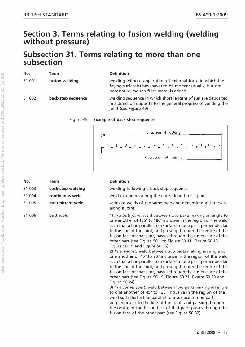
raising standards worldwide™
NO COPYING WITHOUT BSI PERMISSION EXCEPT AS PERMITTED BY COPYRIGHT LAW
BSI British Standards
WB9423_BSI_StandardColCov_noK_AW:BSI FRONT COVERS 5/9/08 12:55 Page 1
raising standards worldwide™
NO COPYING WITHOUT BSI PERMISSION EXCEPT AS PERMITTED BY COPYRIGHT LAW
BSI British Standards
WB9423_BSI_StandardColCov_noK_AW:BSI FRONT COVERS 5/9/08 12:55 Page 1
Welding terms and symbols
Part 1: Glossary for welding, brazing and thermal cutting
BS 499-1:2009
raising standards worldwide™
NO COPYING WITHOUT BSI PERMISSION EXCEPT AS PERMITTED BY COPYRIGHT LAW
BSI British Standards
Lice
nsed
cop
y: N
ES
L us
er, N
ucle
ar E
ngin
eerin
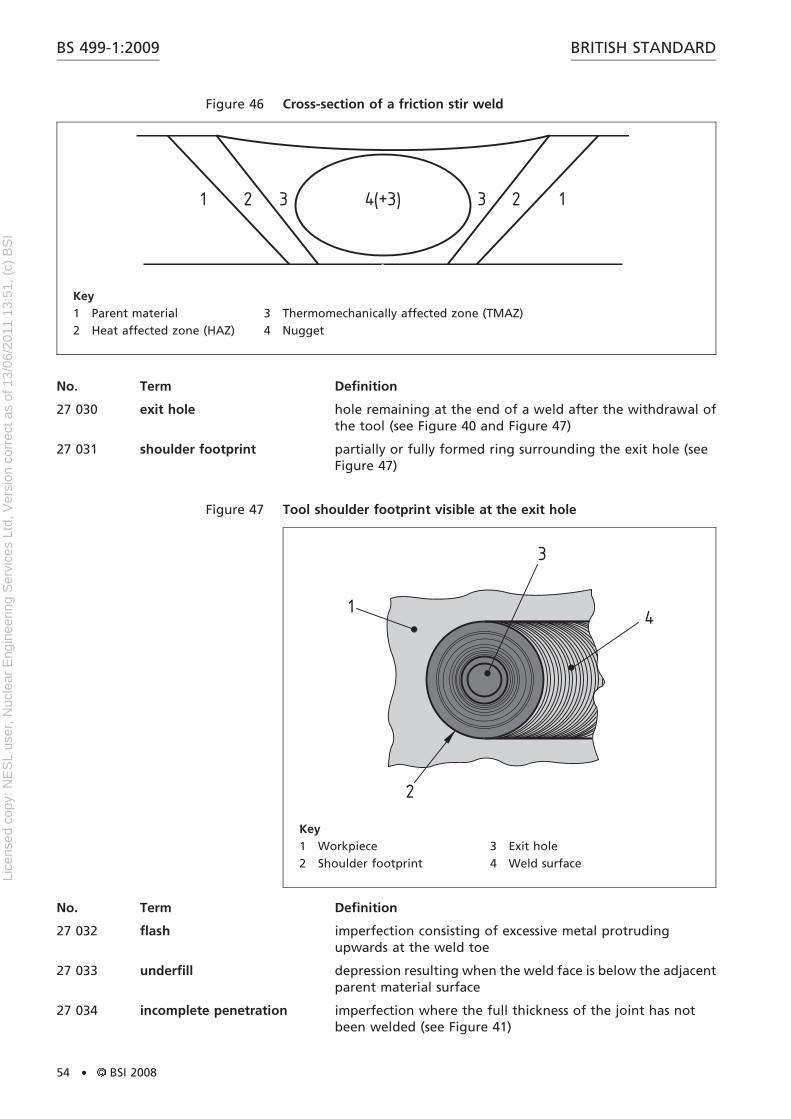
g S
ervi
ces
Ltd,
Ver
sion
cor
rect
as
of 1
3/06
/201
1 13
:51,
(c)
BS
I
Publishing and copyright informationThe BSI copyright notice displayed in this document indicates when the document was last issued
The following BSI references relate to the work on this standard:Committee reference WEE/1Draft for comment 08/30162761 DC
Publication historyFirst published August 1933Second edition June 1939Third edition October 1952Fourth edition October 1965Fifth edition November 1983Sixth edition February 1991Seventh edition December 2008
Amendments issued since publication
Date Text affected
BRITISH STANDARDBS 499-1:2009
Lice
nsed
cop
y: N
ES
L us
er, N
ucle
ar E
ngin
eerin
g S
ervi
ces
Ltd,
Ver
sion
cor
rect
as
of 1
3/06
/201
1 13
:51,
(c)
BS
I
Contents
Foreword v
1 Scope 1
Section 1. Terms common to more than one section 2
Section 2. Terms relating to welding with pressure 19Subsection 21. Terms relating to more than one subsection 19Subsection 22. Terms relating only to resistance welding 28Subsection 23. Terms relating only to friction welding 47Subsection 24. Terms relating only to pressure welding 48Subsection 25. Terms relating only to diffusion welding 48Subsection 26. Terms relating only to explosive welding 49Subsection 27. Terms relating only to friction stir welding 49
Section 3. Terms relating to fusion welding (welding withoutpressure) 57Subsection 31. Terms relating to more than one subsection 57Subsection 32. Terms relating only to arc welding 87Subsection 33. Terms relating only to gas welding 98Subsection 34. Terms relating only to electron beam welding 103Subsection 35. Terms relating only to light radiation welding 106Subsection 36. Terms relating only to aluminothermic welding 107Subsection 37. Terms relating only to electro-slag welding 109
Section 4. Terms relating to braze welding and brazing 110Subsection 40. Terms relating only to braze welding 110Subsection 41. Terms relating only to brazing 111
Section 5. Terms relating to testing 113
Section 6. Terms relating to weld imperfections 118
Section 7. Terms relating to cutting 123Subsection 70. Terms relating to more than one subsection 123Subsection 71. Terms relating only to oxygen cutting 126Subsection 72. Terms relating only to arc cutting 128Subsection 73. Terms relating only to spark erosion cutting 128Subsection 74. Terms relating only to electron beam cutting 129Subsection 75. Terms relating only to laser cutting 129
Section 8. Terms relating to health and safety 130
Bibliography 131
Index 133
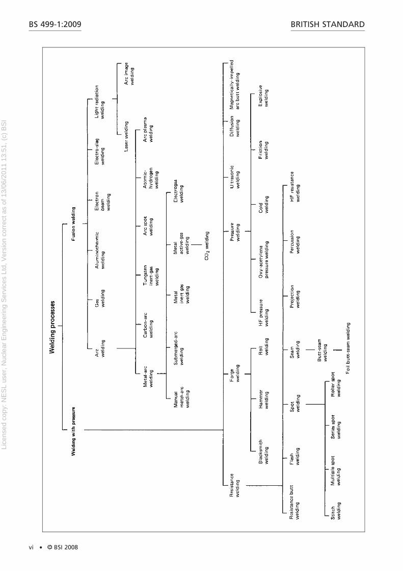
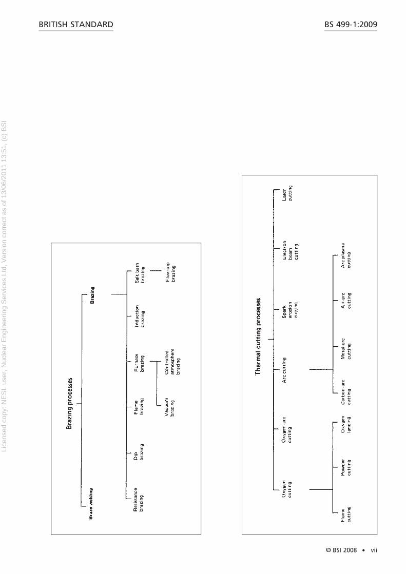
List of figuresFigure 1 – Chart of derivation of welding processes viFigure 2 – Chart of derivation of brazing processes viiFigure 3 – Chart of derivation of thermal cutting processes viiFigure 4 – Root, fusion penetration, weld junction and zones of typicalwelds 3Figure 5 – Preparation for square butt weld 7Figure 6 – Preparation for butt weld between plates with raisededges 7Figure 7 – Preparation for single bevel butt weld with backing 9Figure 8 – Configuration for double-covered lap joint 10Figure 9 – Configuration for single lapped joint 11Figure 10 – Preparation for single V-butt weld 12Figure 11 – Oxy-fuel gas pressure welding 20
BS 499-1:2009BRITISH STANDARD
BSI 2008 . i
Lice
nsed
cop
y: N
ES
L us
er, N
ucle
ar E
ngin
eerin
g S
ervi
ces
Ltd,
Ver
sion
cor
rect
as
of 1
3/06
/201
1 13
:51,
(c)
BS
I
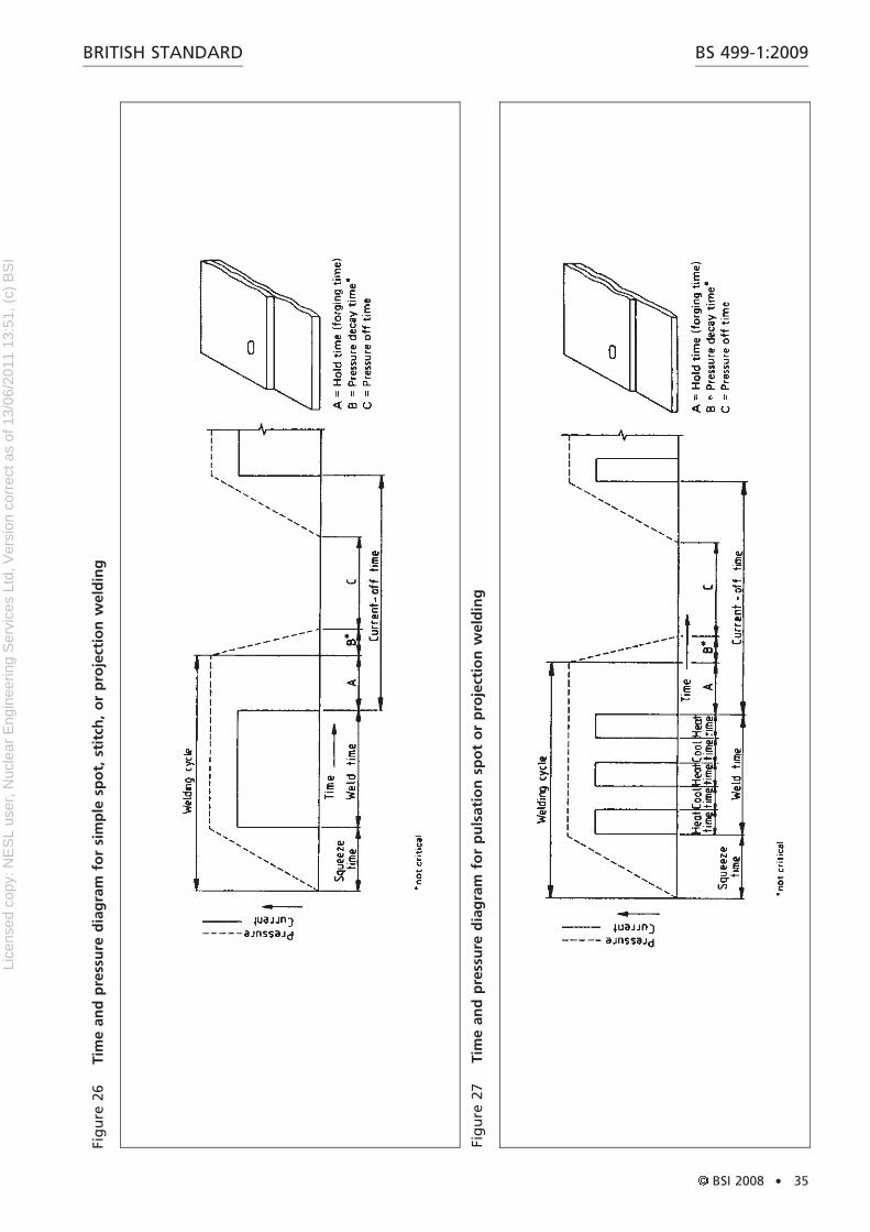
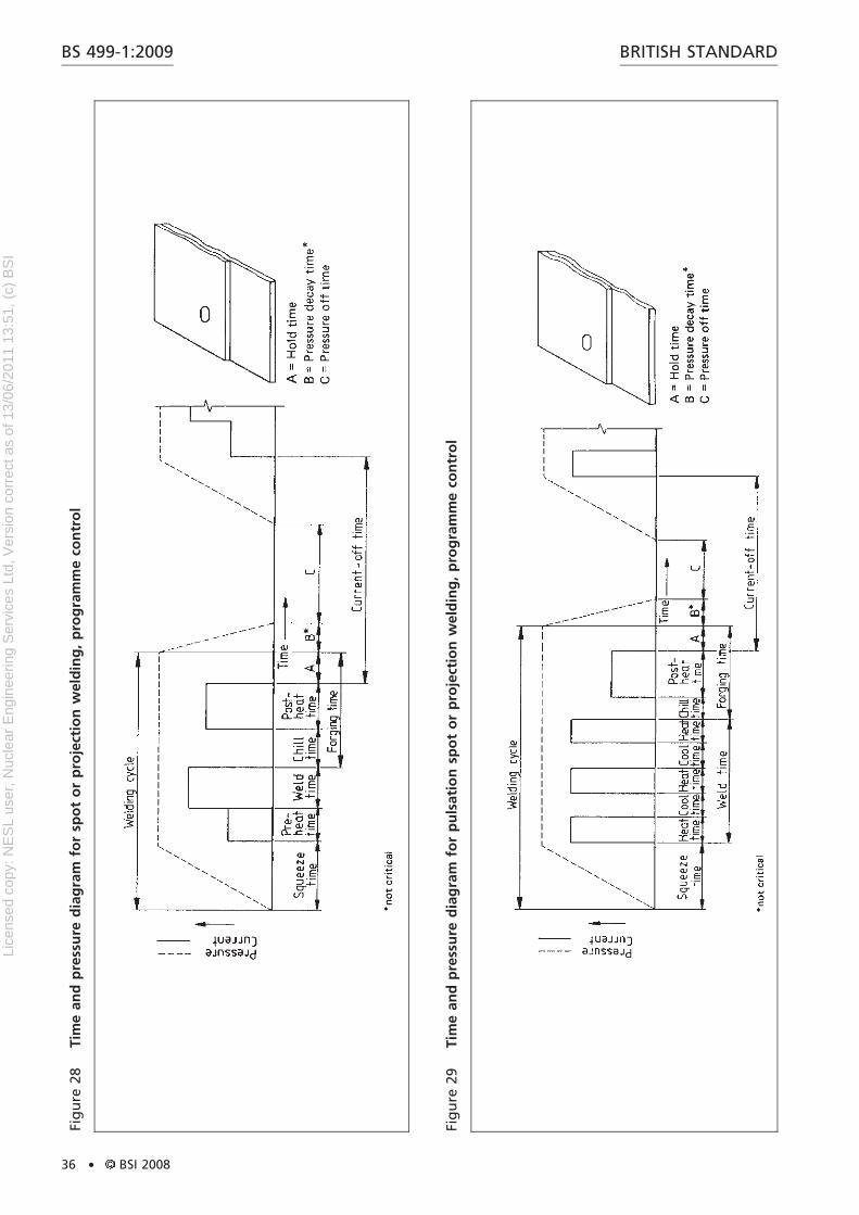
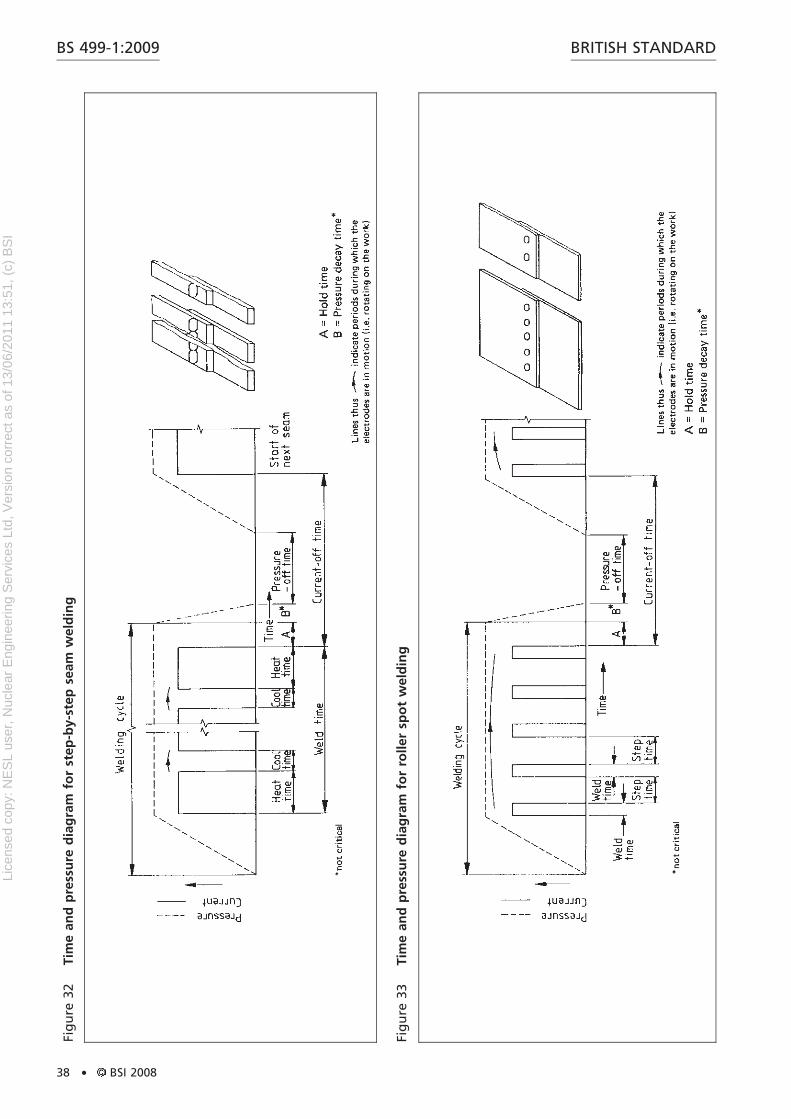
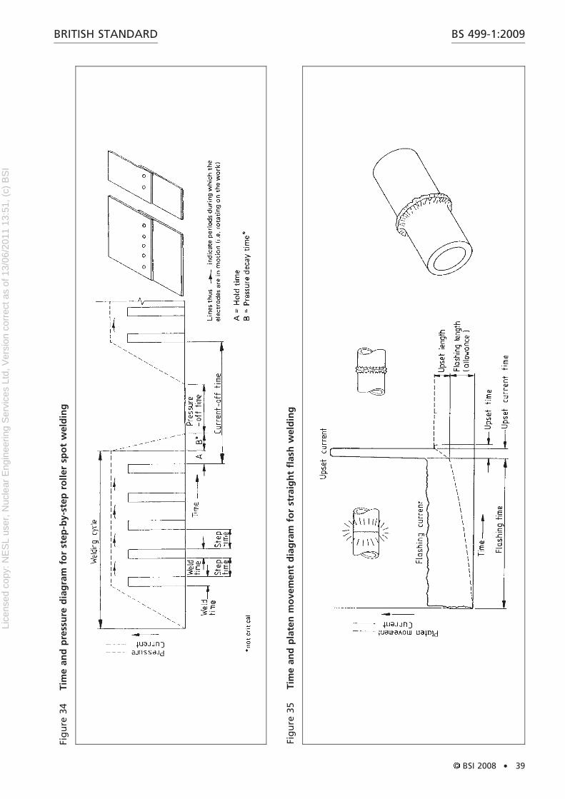
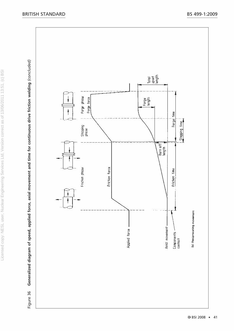
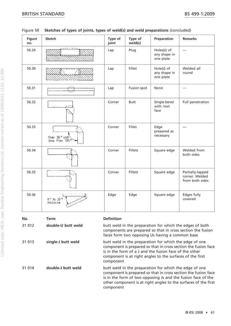
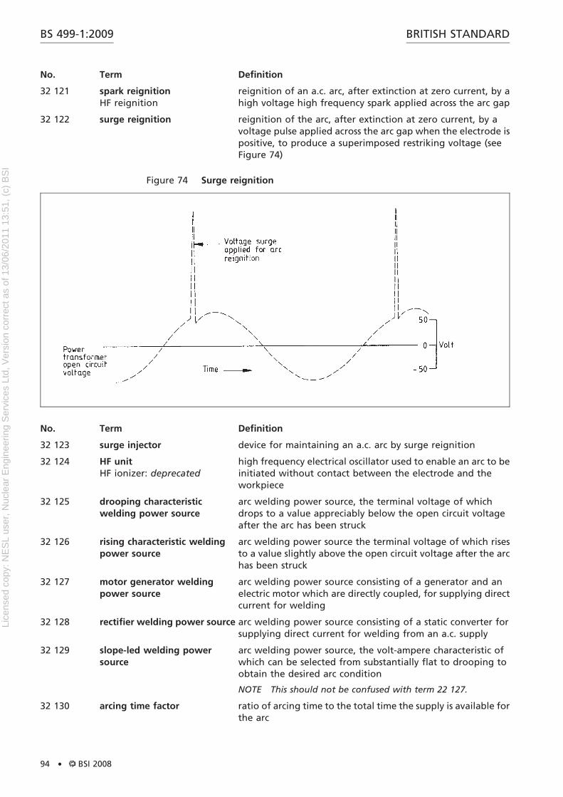
Figure 12 – Examples of series spot welding 22Figure 13 – Forms of projection welds 25Figure 14 – Typical example of weld made using pressure – Double rowof staggered, spaced spot welds 26Figure 15 – Typical example of weld made using pressure – Projectionweld 26Figure 16 – Foil butt-seam weld 27Figure 17 – Weld nugget 28Figure 18 – Typical example of weld made using pressure – Resistancespot welds 28Figure 19 – Typical example of weld made using pressure – Seamweld 29Figure 20 – Mash weld 29Figure 21 – Nail head welding 30Figure 22 – Vertical centre electrode 31Figure 23 – Vertical offset electrode 31Figure 24 – Angle offset electrode 32Figure 25 – Cranked offset electrode 32Figure 26 – Time and pressure diagram for simple spot, stitch, orprojection welding 35Figure 27 – Time and pressure diagram for pulsation spot or projectionwelding 35Figure 28 – Time and pressure diagram for spot or projection welding,programme control 36Figure 29 – Time and pressure diagram for pulsation spot or projectionwelding, programme control 36Figure 30 – Time and pressure diagram for spot welding, programmecontrol with dual-pressure cycle 30Figure 31 – Time and pressure diagram for seam welding 30Figure 32 – Time and pressure diagram for step-by-step seamwelding 38Figure 33 – Time and pressure diagram for roller spot welding 38Figure 34 – Time and pressure diagram for step-by-step roller spotwelding 39Figure 35 – Time and platen movement diagram for straight flashwelding 39Figure 36 – Generalized diagram of speed, applied force, axialmovement and time for continuous drive friction welding 40Figure 37 – Generalized diagram of speed, applied force and axialmovement with time for stored energy friction welding 42Figure 38 – Angle centre electrode 45Figure 39 – Swan-necked electrode 45Figure 40 – Basic principle of friction stir welding 50Figure 41 – Macrosection of a butt weld showing incompletepenetration 50Figure 42 – Heel and heel plunge depth 51Figure 43 – Adjustable probe tool 51Figure 44 – Fixed bobbin tool 52Figure 45 – Self-reacting bobbin tool 52Figure 46 – Cross-section of a friction stir weld 54Figure 47 – Tool shoulder footprint visible at the exit hole 54Figure 48 – Cross-section of friction stir lap weld showing undesirable/extreme plate thinning on the retreating side and a hook feature onthe advancing side of the weld 56Figure 49 – Example of back-step sequence 57Figure 50 –Sketches of types of joints, types of weld(s) and weldpreparations 58
BS 499-1:2009 BRITISH STANDARD
ii . BSI 2008
Lice
nsed
cop
y: N
ES
L us
er, N
ucle
ar E
ngin
eerin
g S
ervi
ces
Ltd,
Ver
sion
cor
rect
as
of 1
3/06
/201
1 13
:51,
(c)
BS
I
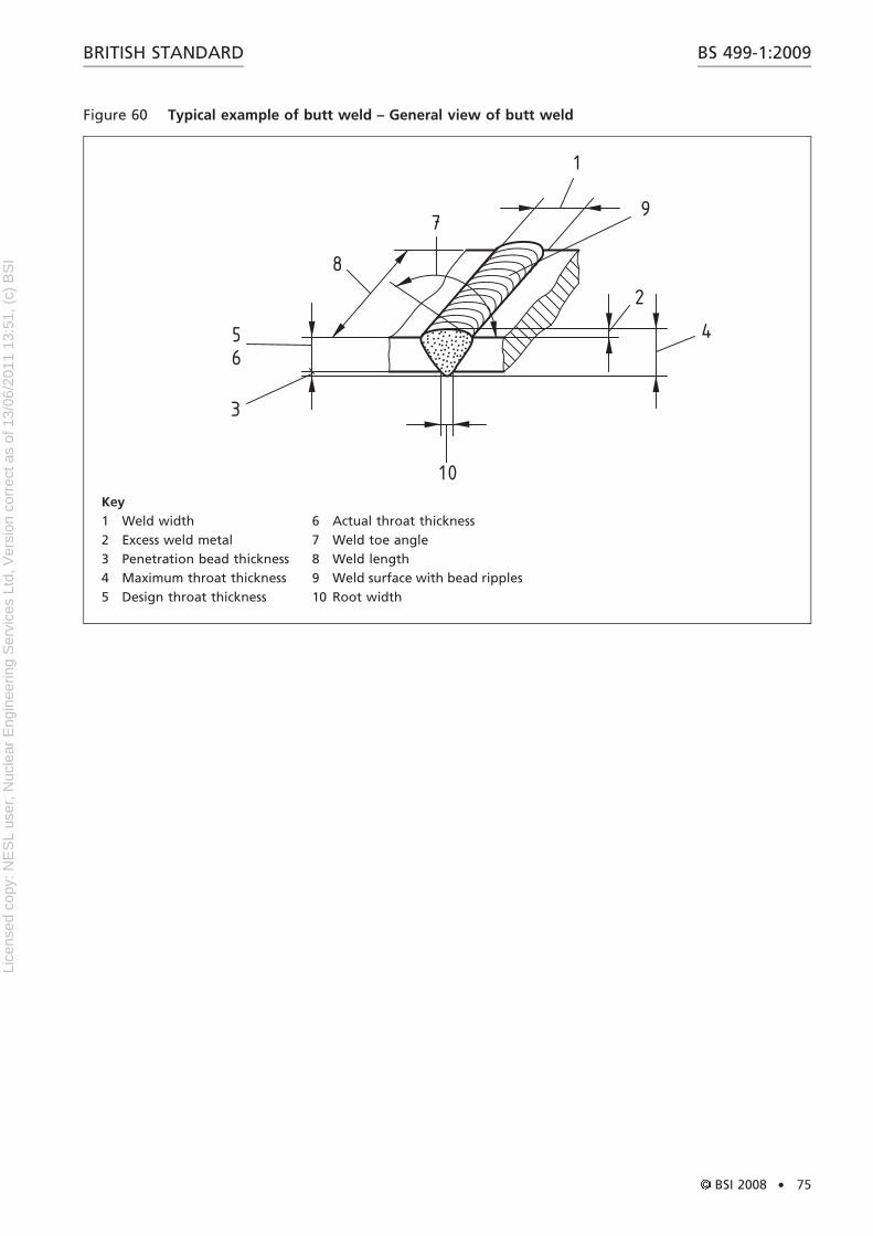
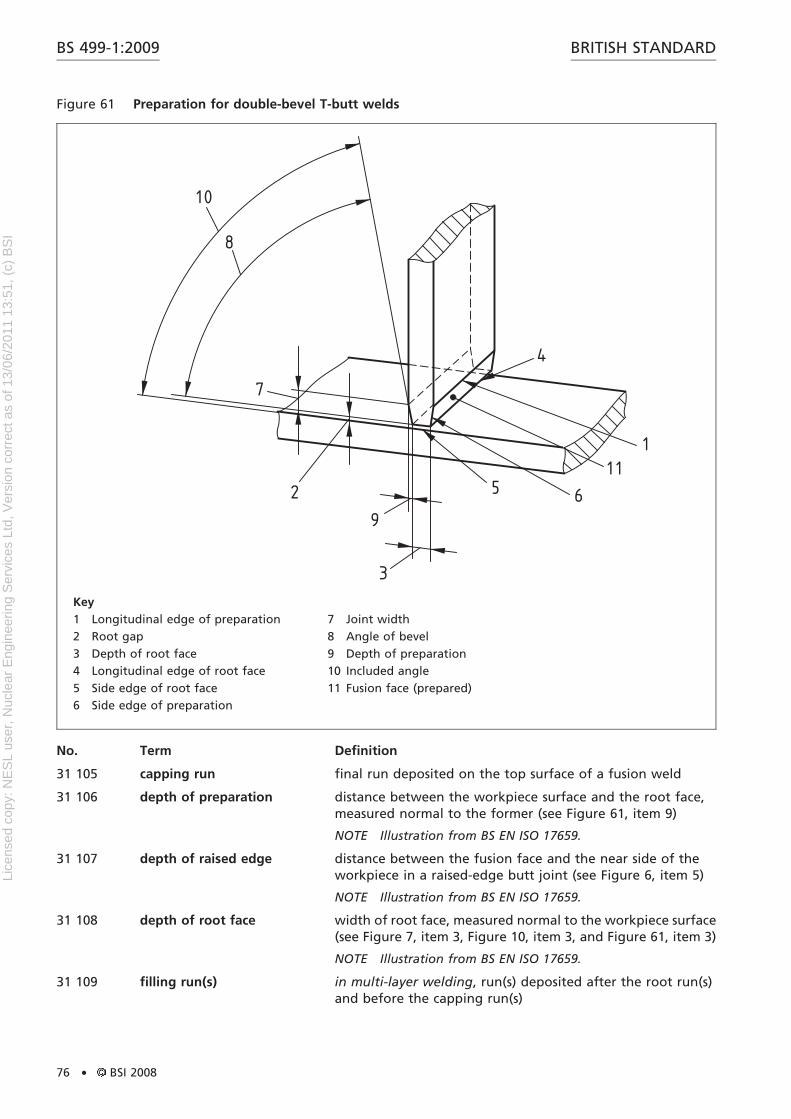
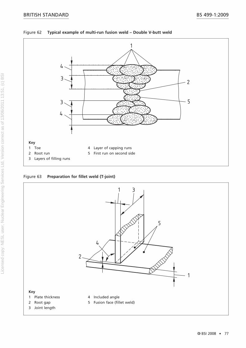
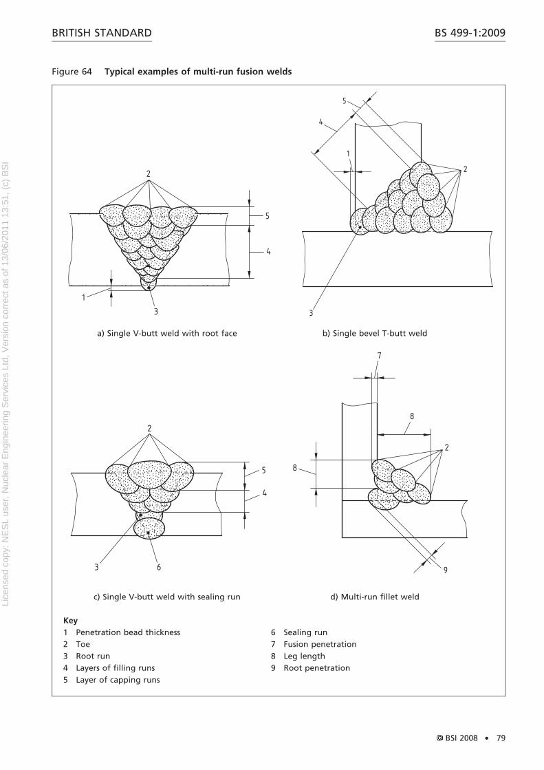
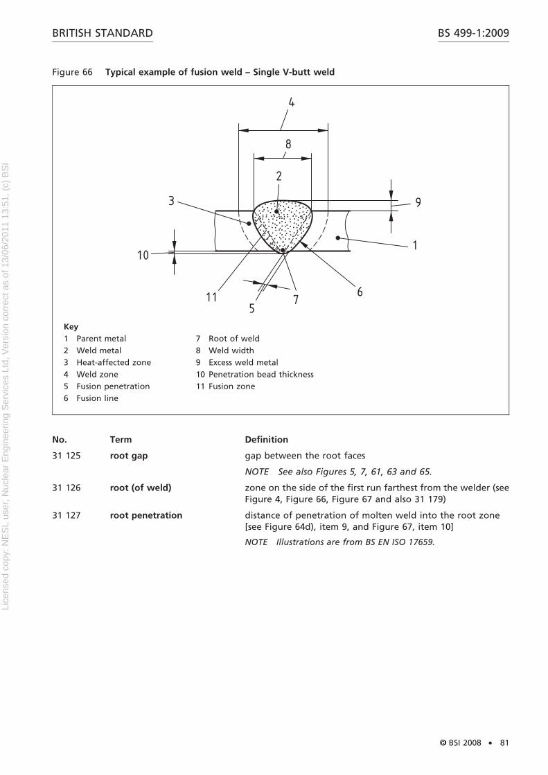
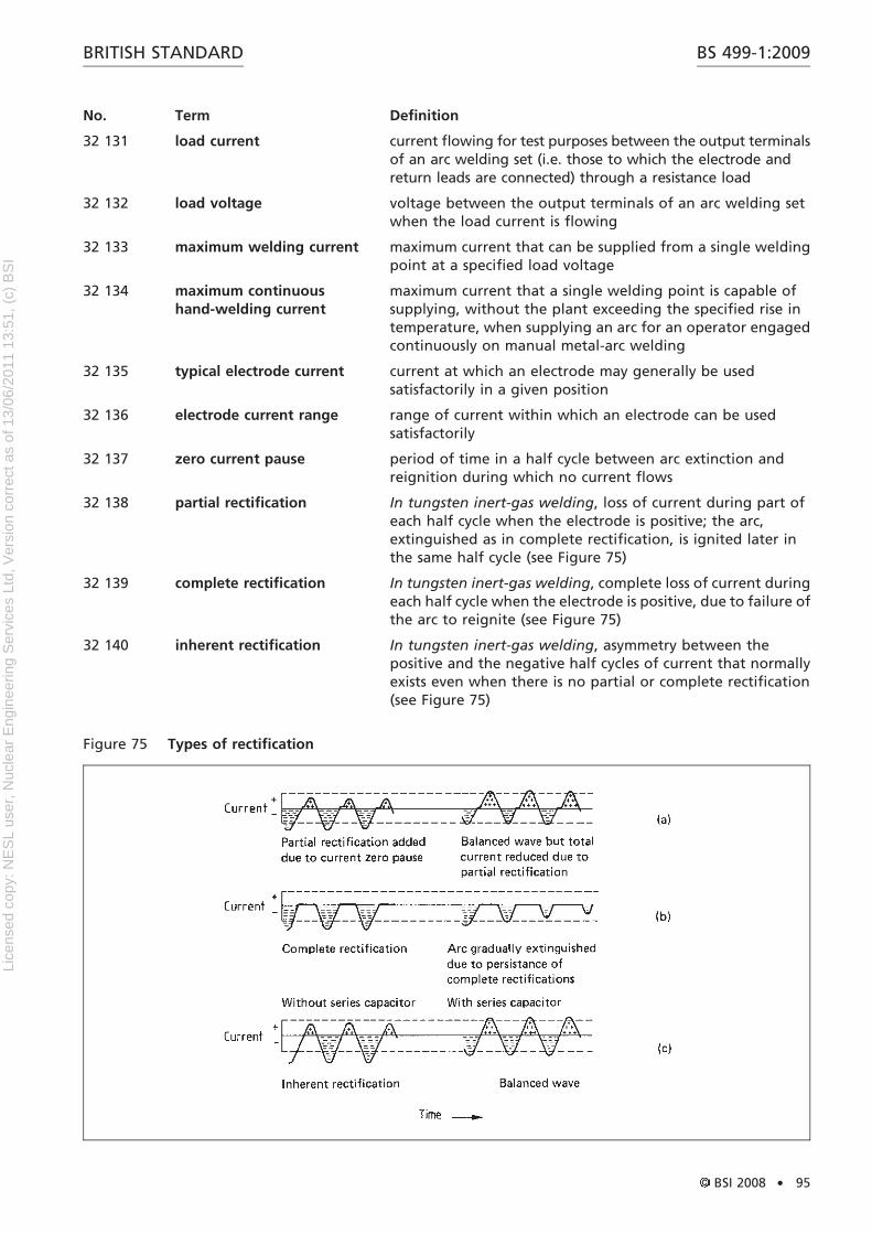
Figure 51 – Gap, root face, root radius, land, included angle and angleof bevel for typical weld preparations 64Figure 52 – Examples of toes, legs, weld widths and fusion faces 66Figure 53 – Actual, effective, design and maximum throat thickness oftypical welds 67Figure 54 – Examples of excess weld metal 68Figure 55 – Welding positions: slope (S) 70Figure 56 – Schematic diagram of main welding positions 70Figure 57 – Simplified view of main welding positions 71Figure 58 – Comparison of UK (USA) and ISO welding positions 71Figure 59 – Weld preparation using a fusible insert 73Figure 60 – Typical example of butt weld – General view of buttweld 75Figure 61 – Preparation for double-bevel T-butt welds 76Figure 62 – Typical example of multi-run fusion weld – Double V-buttweld 77Figure 63 – Preparation for fillet weld (T-joint) 77Figure 64 – Typical examples of multi-run fusion welds 79Figure 65 – Preparation for single U-butt weld 80Figure 66 – Typical example of fusion weld – Single V-butt weld 81Figure 67 – Typical example of fusion weld – Fillet weld 82Figure 68 – Weave technique 84Figure 69 – Example of skip sequence 84Figure 70 – Examples of block sequences 85Figure 71 – Roots of typical weld preparations 86Figure 72 – Penetration bead 86Figure 73 – Self-shielded tubular-cored arc welding 92Figure 74 – Surge reignition 94Figure 75 – Types of rectification 95Figure 76 – Neutral oxy-acetylene flame 98Figure 77 – Carburizing oxy-acetylene flame 99Figure 78 – Carburizing oxy-acetylene flame for a hard surfacingapplication 99Figure 79 – Oxidizing oxy-acetylene flame 99Figure 80 – Leftward welding 99Figure 81 – Rightward welding 99Figure 82 – All-position rightward welding 102Figure 83 – Diagrammatic representation of a diode gun 104Figure 84 – Diagrammatic representation of a triode gun 104Figure 85 – Diagrammatic representation of a back-bombardedgun 105Figure 86 – Basic equipment for aluminothermic welding 108Figure 87 – Electro-slag welding 109Figure 88 – Bell butt joint 110Figure 89 – Diminishing bell butt joint 110Figure 90 – Short bell branch joint 111Figure 91 – U-tensile test specimen 115Figure 92 – Cruciform test pieces 115Figure 93 – Method of obtaining cruciform test specimen 116Figure 94 – Tongue-bend test specimen 116Figure 95 – Shear test piece 117Figure 96 – Incompletely filled groove 118Figure 97 – Undercut 118Figure 98 – Lack of sidewall fusion 119Figure 99 – Lack of root fusion 119Figure 100 – Lack of inter-run fusion 119Figure 101 – Incomplete root penetration 119
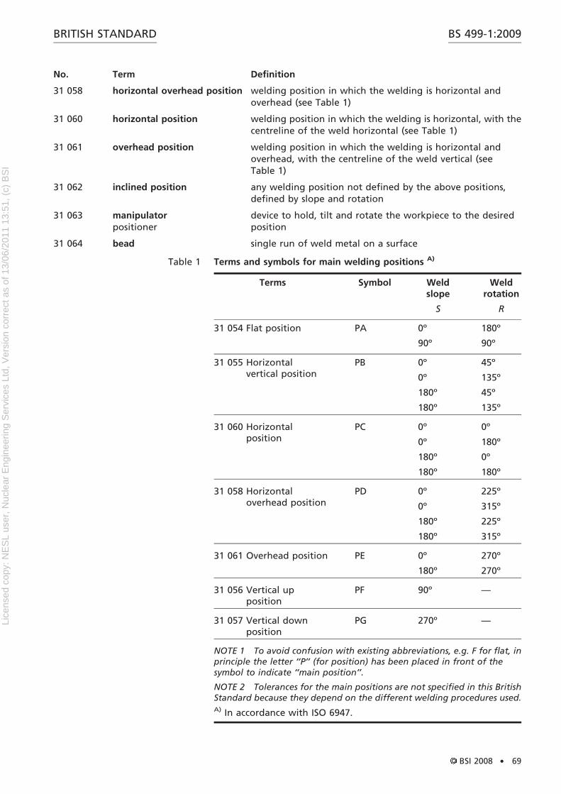
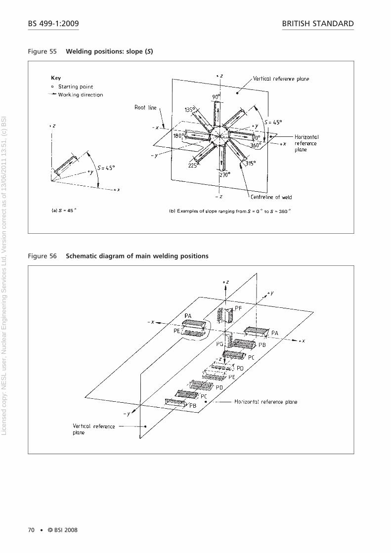
List of tablesTable 1 – Terms and symbols for main welding positions 69
Summary of pages
This document comprises a front cover, an inside front cover, pages ito viii, pages 1 to 142, an inside back cover and a back cover.
BS 499-1:2009 BRITISH STANDARD
iv . BSI 2008
Lice
nsed
cop
y: N
ES
L us
er, N
ucle
ar E
ngin
eerin
g S
ervi
ces
Ltd,
Ver
sion
cor
rect
as
of 1
3/06
/201
1 13
:51,
(c)
BS
I
Foreword
Publishing information
This part of BS 499 is published by BSI and came into effect on 31December 2008. It was prepared by Technical Committee WEE/1,Definition and symbols for welding. A list of organizationsrepresented on this committee can be obtained on request to itssecretary.
Supersession
This part of BS 499 supersedes BS 499-1:1991, which is withdrawn.
Relationship with other publications
This standard has been aligned, as far is as practicable, with existingEuropean and international lists of terms and definitions for welding,including BS EN 1792:2003, PD CEN/TR 14599, BS ISO 857 (all parts)and BS EN 13622. There might not be full agreement with standardsthat have not been adopted as British Standards. Where it was feltthat an existing definition needed clarification, this has been donewhile striving to not contradict the existing definition. As far aspracticable, the numbering system used in this standard follows thatof BS EN 1792:2003 with new numbers allocated to terms that are notin the European standard.
Where definitions are based on those in a European or internationalstandard, the identifier of the original standard is given in squarebrackets after the definition.
BS 499 is published in two parts, with a supplement to this part:
* Part 1: Glossary for welding, brazing and thermal cutting
* Part 1, Supplement: Definitions for electric welding equipment
* Part 2c: European arc welding symbols in chart form
NOTE 1 BS 499-1, Supplement is a reproduction of IEV 50 (851):1991.
NOTE 2 BS 499-2c is based on BS EN 22553.
Information about this document
This is a full revision of the standard, and introduces the followingprincipal changes:
Charts showing the derivation of welding, cutting and allied processesare given in Figure 1, Figure 2 and Figure 3.
Commonly used friction stir welding terms are included in the newSection 27.
Contractual and legal considerations
This publication does not purport to include all the necessaryprovisions of a contract. Users are responsible for its correctapplication.
Compliance with a British Standard cannot confer immunity fromlegal obligations.
BS 499-1:2009BRITISH STANDARD
BSI 2008 . v
Lice
nsed
cop
y: N
ES
L us
er, N
ucle
ar E
ngin
eerin
g S
ervi
ces
Ltd,
Ver
sion
cor
rect
as
of 1
3/06
/201
1 13
:51,
(c)
BS
I
BS 499-1:2009 BRITISH STANDARD
vi . BSI 2008
Lice
nsed
cop
y: N
ES
L us
er, N
ucle
ar E
ngin
eerin
g S
ervi
ces
Ltd,
Ver
sion
cor
rect
as
of 1
3/06
/201
1 13
:51,
(c)
BS
I
BS 499-1:2009BRITISH STANDARD
BSI 2008 . vii
Lice
nsed
cop
y: N
ES
L us
er, N
ucle
ar E
ngin
eerin
g S
ervi
ces
Ltd,
Ver
sion
cor
rect
as
of 1
3/06
/201
1 13
:51,
(c)
BS
I
BS 499-1:2009 BRITISH STANDARD
viii . BSI 2008 This page deliberately left blank.
Lice
nsed
cop
y: N
ES
L us
er, N
ucle
ar E
ngin
eerin
g S
ervi
ces
Ltd,
Ver
sion
cor
rect
as
of 1
3/06
/201
1 13
:51,
(c)
BS
I
1 ScopeThis standard provides terms, symbols and definitions for welding,brazing and thermal cutting of metals. Some definitions might alsoapply to non-metals.
It does not cover mechanically fastened or adhesive bonded joints.
This standard is intended for designers, those drafting weldingspecifications, welding production, manufacturers and inspectionpersonnel.
Preferred and equivalent terms are given in bold type. Non-preferredterms are given in medium type. Deprecated terms are indicated assuch.
BS 499-1:2009BRITISH STANDARD
BSI 2008 . 1
Lice
nsed
cop
y: N
ES
L us
er, N
ucle
ar E
ngin
eerin
g S
ervi
ces
Ltd,
Ver
sion
cor
rect
as
of 1
3/06
/201
1 13
:51,
(c)
BS
I
Section 1. Terms common to more than one section
No. Term Definition
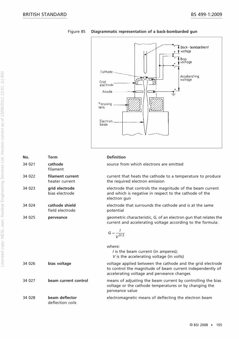
10 001 welding joining process in which two or more parts are unitedproducing a continuity in the nature of the workpiecematerial(s) by means of heat or pressure or both, and with orwithout the use of filler material
10 002 weld union of pieces of material resulting from welding
10 003 welder operator who performs or controls the welding process
10 004 welding operator person who controls fully mechanized or automatic fusionwelding processes
10 005 welding plantwelder: deprecated
apparatus for providing and controlling energy, andmovement if necessary, for making a weld
10 006 welding process particular method of welding involving the application ofcertain metallurgical, electrical, physical or mechanicalprinciples
10 007 manual welding welding where the electrode holder, welding hand gun, torchor blowpipe is manipulated by hand
10 008 partly mechanized welding manual welding where the wire feed is mechanized
10 010 mechanized welding welding in which the welding parameters are maintainedwithin a suitable tolerance by mechanical or electronic meansand which may be manually varied during the weldingprocess to create the required welding conditions
10 011 automatic welding welding in which all operations are preset and performedautomatically during the process
10 012 strength weld weld designed to withstand stress
10 013 parent metalbase metal: deprecated
metal to be joined or surfaced by welding, braze welding orbrazing (See Figure 4.)
10 014 filler metal welding consumable added during welding to form the weld
10 015 filler wirewelding wire
filler material in the form of a wire which may or may not be apart of the welding circuit
10 016 filler rodwelding rod: deprecated
filler material in the form of a rod which may or may not be apart of the welding circuit
10 017 flux material used during welding, brazing or braze welding toclean the surfaces of the joint chemically, to preventatmospheric oxidation and to reduce impurities
NOTE In arc welding, many other substances, which performspecial functions, are added.
10 018 deposited metal filler metal that has been added during welding
10 020 weld metal all metal melted during the making of a weld and retained inthe weld (See Figure 4.)
10 021 runpass
metal melted or deposited during one passage of anelectrode, or torch or blowpipe
BS 499-1:2009 BRITISH STANDARD
2 . BSI 2008
Lice
nsed
cop
y: N
ES
L us
er, N
ucle
ar E
ngin
eerin
g S
ervi
ces
Ltd,
Ver
sion
cor
rect
as
of 1
3/06
/201
1 13
:51,
(c)
BS
I
No. Term Definition
10 022 deposition rate mass of filler metal consumed per unit of productive weldingtime
10 023 weld zone zone containing the weld metal and the heat-affected zone(See Figure 4.)
10 024 heat-affected zoneHAZ
portion of non-melted parent metal whose microstructure hasbeen affected (See Figure 4.)
10 025 fusion zone part of the parent metal that is melted into the weld metal, asdetermined on the cross-section of a weld (See Figure 4.)
10 026 fusion line interface between the weld metal and the non-melted parentmetal as determined on the cross-section of a fusion weld
10 027 welding technique manner in which an operator manipulates an electrode, ablowpipe or a similar appliance
10 028 welding procedure specific course of action followed in welding, including a listof materials and, where necessary, tools to be used (SeeAnnex A to Annex G.)
10 030 (welding) sequence order and direction in which joints, welds or runs are made
10 031 weld run sequence order in which the runs of a weld or deposited layer areproduced
10 032 stud welding joining of a metal stud or similar part to a workpiece
NOTE Welding may be accomplished by arc, resistance, frictionor other suitable process, with or without external gas shielding.The weld is made over the whole end area of the stud orattachment.
10 033 hard facinghard surfacing
application of a hard, wear-resistant material to the surface ofa component by welding, braze welding or spraying
10 034 spatter globules of metal expelled during welding or cutting
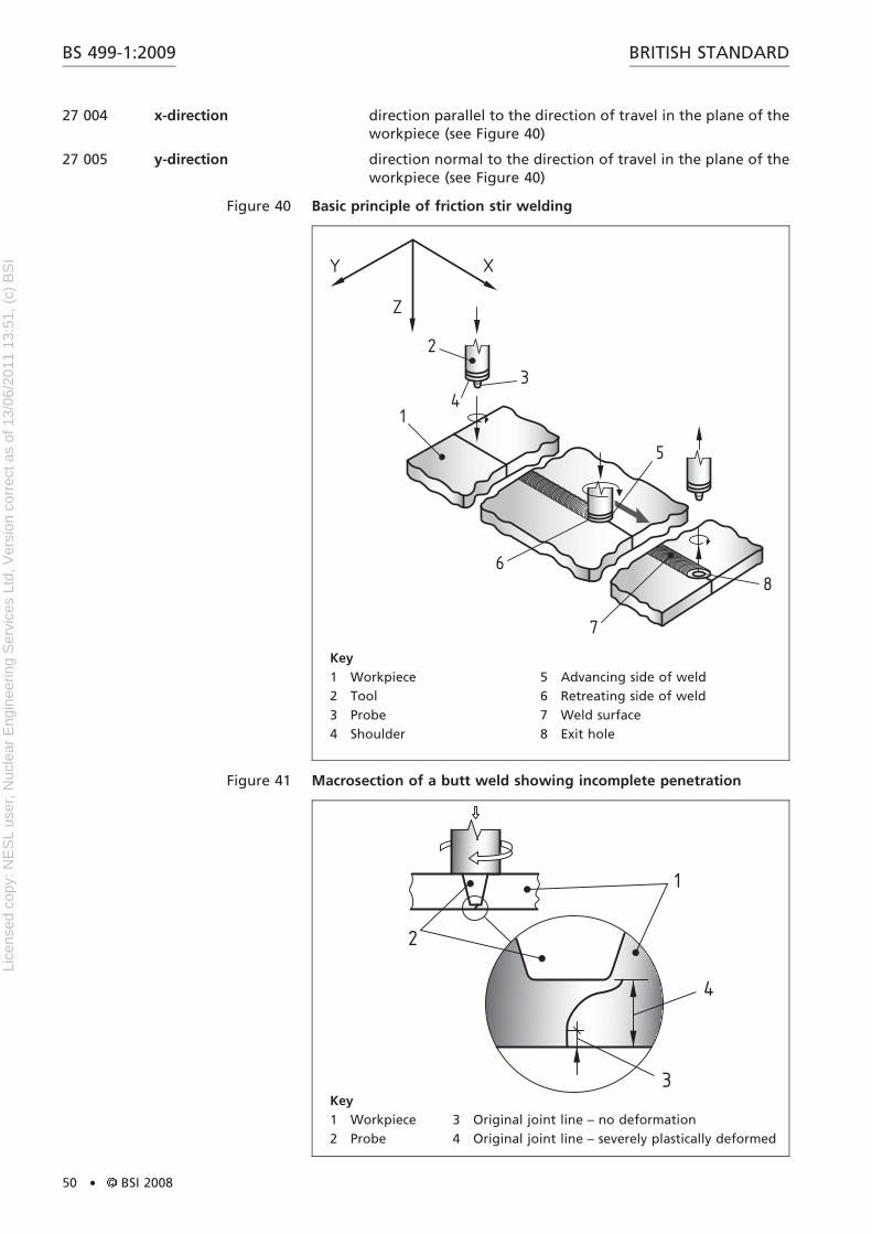
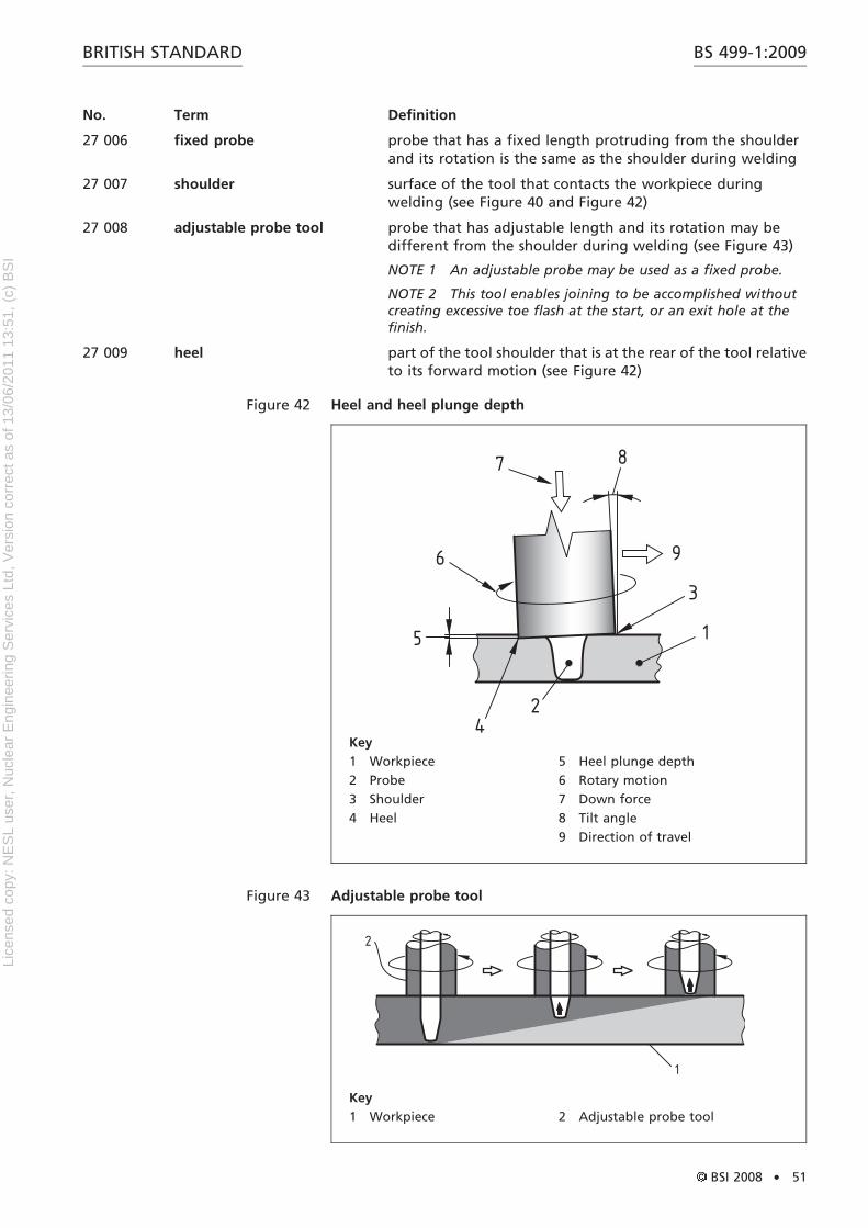
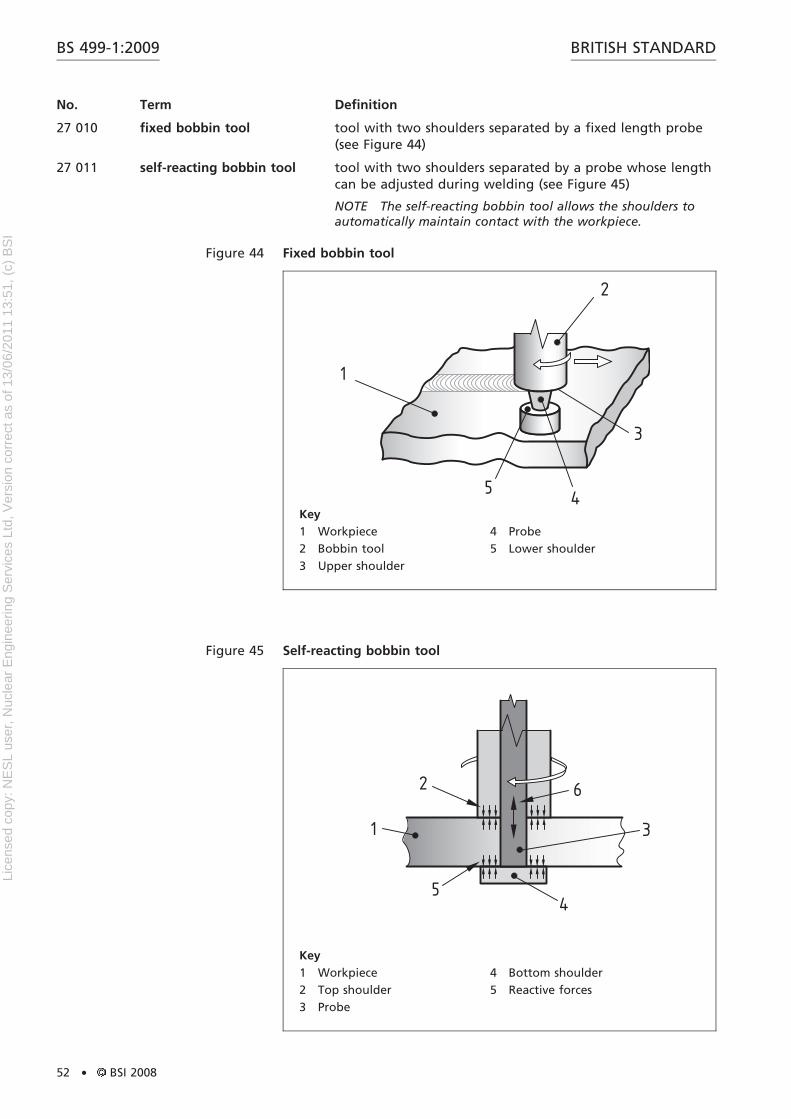
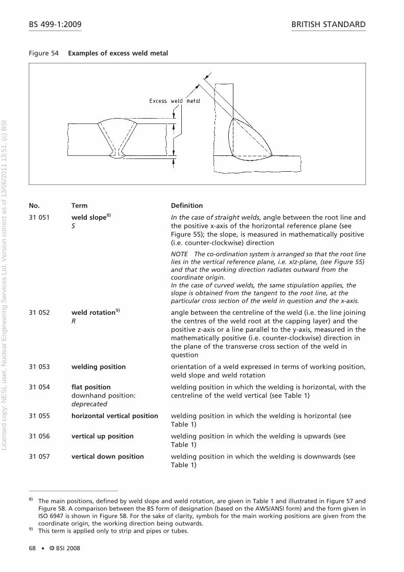
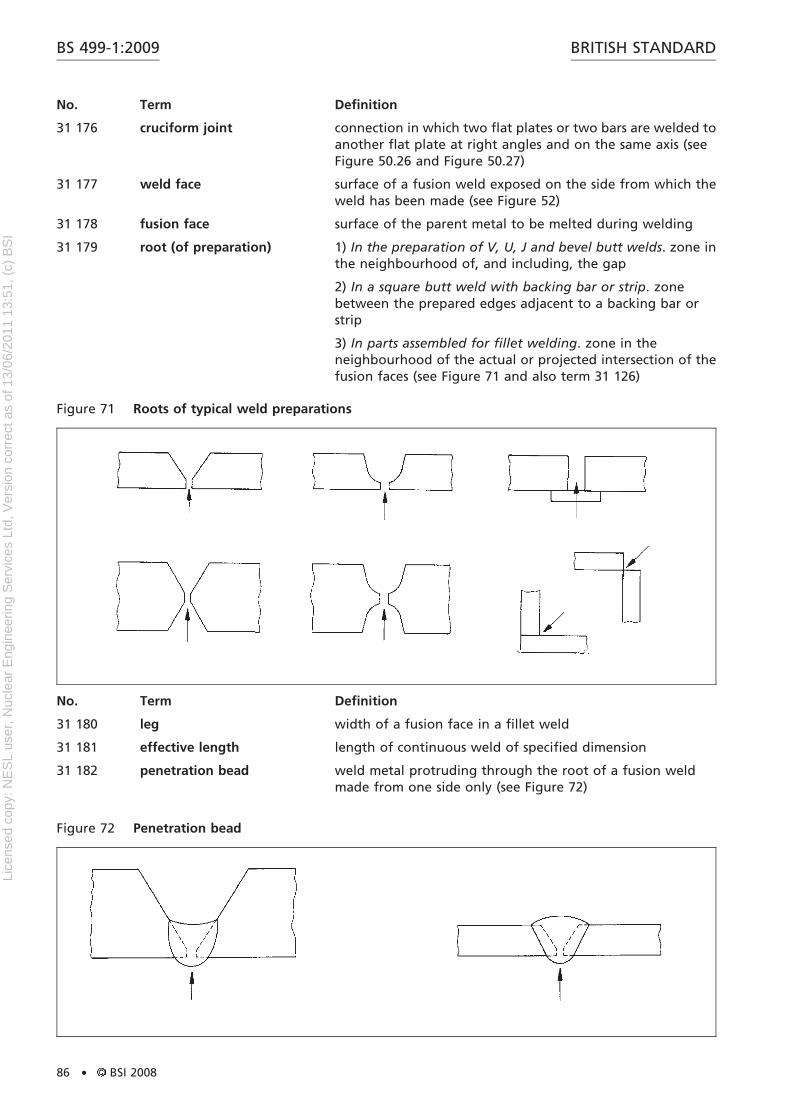
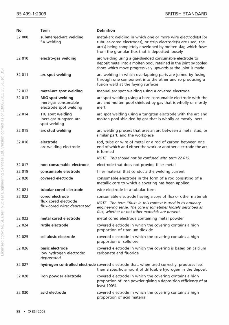
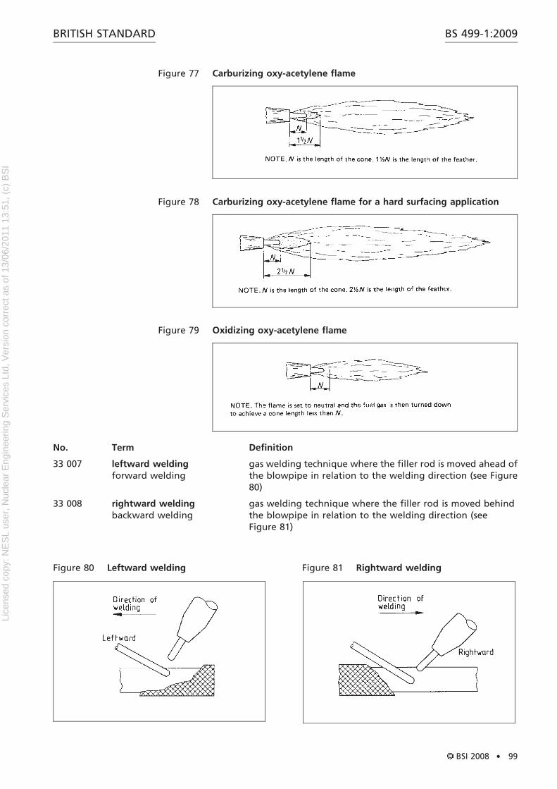
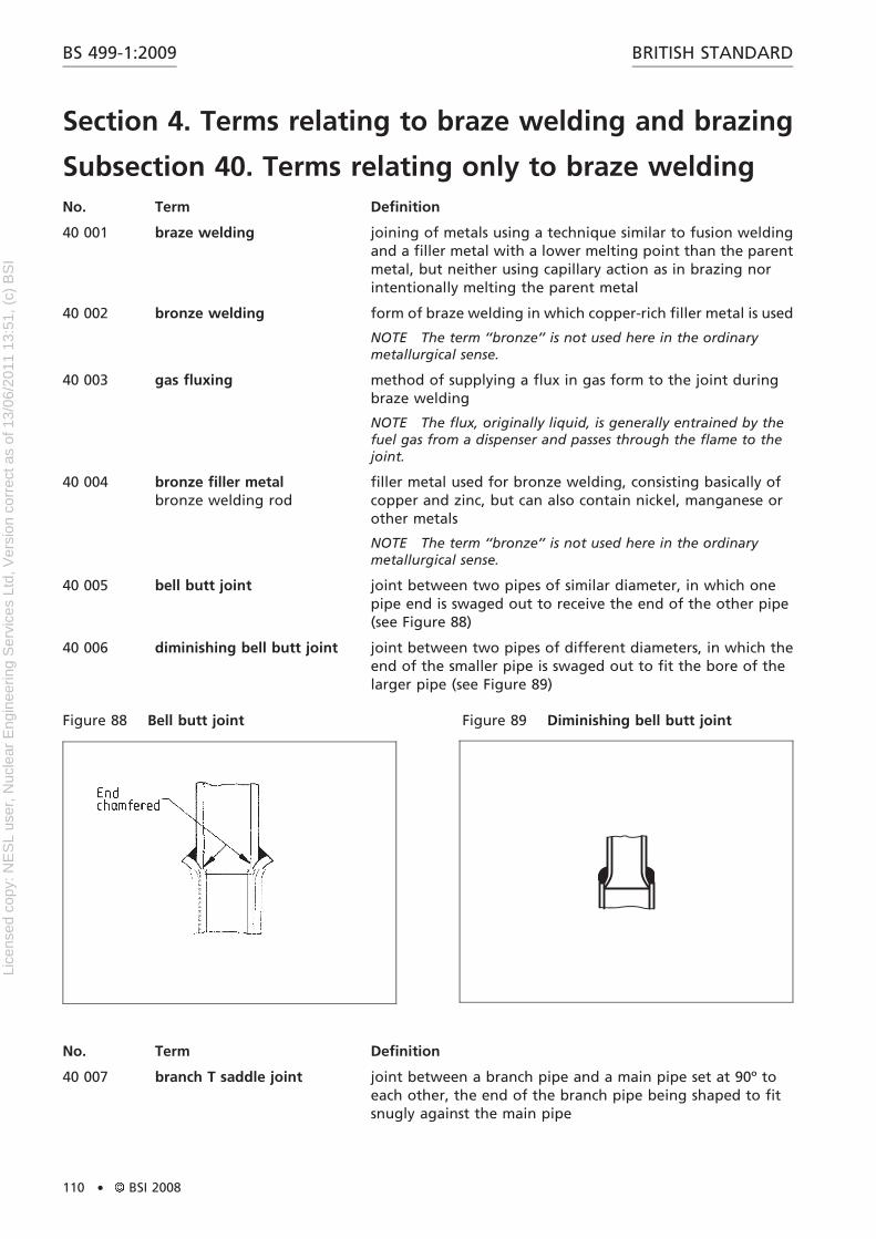
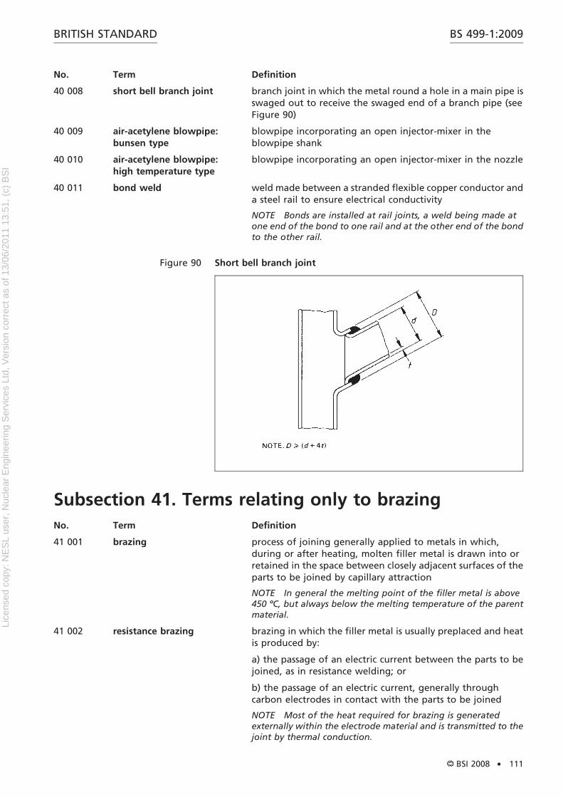
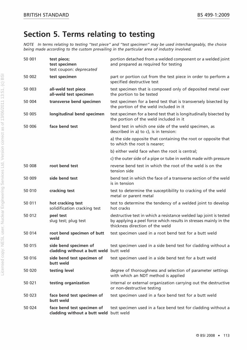
Figure 4 Root, fusion penetration, weld junction and zones of typical welds
10 035 duty cycle 1) In the sense of ‘‘welding operator’’ duty cycle, ratio of timespent welding to the total time which includes otheractivities, e.g. changing electrodes, slag removal
2) In the sense of ‘‘machine’’ duty cycle, measure of thecapability of the welding equipment
10 036 transferred arc arc established between the electrode of the plasma arc torchand the workpiece
10 037 non-transferred arc arc established between the electrode and the constrictingnozzle of the plasma arc torch or thermal spraying gun
NOTE The workpiece does not form part of the electrical circuit.
10 038 electrode pick-up contamination of a non-consumable electrode by metal orscale from the surface of the workpiece
10 040 pick-up 1) In fusion welding, transfer of alloying elements from theparent metal to the weld metal as a result of dilution
2) In resistance welding, particles of the surface of theworkpiece that adhere to the surface of the electrodes, or viceversa
10 041 arc eye irritation of the eye caused by exposure to radiation from anelectric arc
10 042 electrode holder device to hold an electrode and to convey current to it
NOTE 1 In resistance welding, this is device holding a spotwelding electrode.
NOTE 2 In arc welding, this is a tool for clamping, guiding andconnecting a covered electrode to the welding circuit whileinsulating the operator from the welding
10 043 welding glassfilter glass
special filter that provides protection against glare whenwelding and in addition reduces the UV radiation and IRradiation that is dangerous to the human eye
10 044 heat filter colourless, transparent, heat-absorbing glass plate placedbetween the plain glass and the welding glass to protect theeyes
NOTE It is usually used in high current metal inert-gas welding.
10 045 blowpipetorch: deprecated
device for mixing and burning gases to produce a flame forwelding, brazing, braze welding, cutting, heating and similaroperations (See also terms 32 142 to 32 144.)
10 046 flashback retrogression of the flame beyond the blowpipe body into thehose, with possible subsequent explosion
10 047 pressure regulatorgas regulator
device for attachment to a gas cylinder or pipeline forreducing and regulating the gas pressure to the workingpressure required
10 048 residual welding stress stress remaining in a metal part or structure as a result ofwelding
10 050 pulse unidirectional flow of current of either polarity of briefduration
10 051 pulse time duration of a pulse
BS 499-1:2009 BRITISH STANDARD
4 . BSI 2008
Lice
nsed
cop
y: N
ES
L us
er, N
ucle
ar E
ngin
eerin
g S
ervi
ces
Ltd,
Ver
sion
cor
rect
as
of 1
3/06
/201
1 13
:51,
(c)
BS
I
No. Term Definition
10 052 welding primerweldable primer: deprecated
paint that is applied to a shot-blasted metal surface forprotective purposes, which does not have to be removed priorto welding and does not prevent the making of a satisfactoryweld
10 053 welding consumables all materials, such as filler materials, gas, flux or paste, used upduring welding and enabling or facilitating the formation ofa weld
10 054 welding equipment basic apparatus used in welding such as power source, as wellas wire feeder and powder feeder, etc.
10 055 welding accessories all items of welding equipment associated with welding,other than welding plant and welding consumables
10 056 layer stratum of weld metal consisting of one or more runs, side byside
10 057 building-up overlay welding to obtain or restore required dimensions
10 058 surfacing producing a layer of metal, by welding, on a workpiece toobtain desired properties or dimensions
10 060 joint preparationweld preparation
preparation for making a connection where the individualcomponents, suitably prepared and assembled, are joined bywelding or brazing
10 061 joint junction of workpieces or the edges of workpieces that are tobe joined or have been joined
10 063 air gapgap
1) In fusion welding, minimum distance at any cross-sectionbetween edges, ends or surfaces to be joined
2) In magnetically-impelled arc butt welding, space betweencomponent surfaces across which the arc is maintained duringthe heating (arcing) period
10 064 heat input heat introduced into the joint during welding, referred to acharacteristic dimension, such as a bead or weld length, weldcross-section, weld spot diameter
10 066 acceptance criteria specified quality criteria for defining conformance of a weld
10 067 acceptance level specific set of acceptance criteria where more than one setcan be selected
10 068 examiner person who has been appointed to verify compliance with theapplicable standard
NOTE In certain cases, an external independent examiner can berequired.
10 069 examining body organization that has been appointed to verify compliancewith the applicable standard
NOTE In certain cases, an external independent examining bodycan be required.
10 070 welding procedurespecificationWPS
document that has been qualified and provides the requiredvariables of the welding procedure to ensure repeatabilityduring production welding
10 071 welding procedurequalification recordWPQR
record comprising all necessary data needed for qualificationof a preliminary welding procedure specification
10 073 welding variable variable which influences the characteristics of the weldedjoint
BS 499-1:2009BRITISH STANDARD
BSI 2008 . 5
Lice
nsed
cop
y: N
ES
L us
er, N
ucle
ar E
ngin
eerin
g S
ervi
ces
Ltd,
Ver
sion
cor
rect
as
of 1
3/06
/201
1 13
:51,
(c)
BS
I
No. Term Definition
10 074 essential variable welding condition that requires qualification
10 075 additional variablenon-essential variable
welding condition addressed in the welding procedurespecification but not requiring qualification
10 076 standard material material produced and delivered in accordance with astandard or specification
10 080 re-start point on the run where the welding is or was re-started
10 081 post-weld heat treatment application of heat to an assembly after welding, brazing,soldering, thermal spraying or cutting
10 082 plasma gas ionized gas that generally forms the major portion of an arccolumn and provides a conducting path for the current
10 083 preheat heating of an appropriate area of a workpiece beforewelding, normally to achieve the preheating temperature
10 084 cooling rate rate of decrease of temperature with time over a specifiedtemperature range or time
10 085 heating rate rate of increase of temperature with time over a specifiedtemperature range or time
10 088 dissimilar material joint welded joint in which the parent materials have significantdifferences in mechanical properties and/or chemicalcomposition
10 089 as welded pertaining to the condition of weld metal, welded joints, andweldments after welding, but prior to any subsequentthermal, mechanical, or chemical treatments
NOTE For alloys that may undergo natural ageing (e.g. somealuminium alloys) the as-welded condition lasts only for a limitedperiod of time.
10 090 auxiliary material welding consumable used during welding, generally notforming part of the finished weld
10 091 quality level description of the qualities of a weld on the basis of type, sizeand amount of selected imperfections
10 092 fitness-for-purpose ability of a product, process or service to serve a definedpurpose under specific conditions
10 093 side edge of workpiece edge of workpiece, transverse to weld surface (see Figure 5,item 2)
NOTE Illustration from BS EN ISO 17659.
BS 499-1:2009 BRITISH STANDARD
6 . BSI 2008
Lice
nsed
cop
y: N
ES
L us
er, N
ucle
ar E
ngin
eerin
g S
ervi
ces
Ltd,
Ver
sion
cor
rect
as
of 1
3/06
/201
1 13
:51,
(c)
BS
I
Figure 5 Preparation for square butt weld
4
2
7
3
1
6
58
Key
1 Plate thickness 5 Upper workpiece surface
2 Side edge of workpiece 6 Reverse side
3 Gap 7 Plate edge
4 Joint length 8 Fusion face (unprepared)
Figure 6 Preparation for butt weld between plates with raised edges
2
7
4
3
5
16
Key
1 Plate thickness 5 Depth of raised edge
2 Length of raised edge 6 Radius of raised edge
3 Longitudinal side of raised edge 7 Fusion face (unprepared)
4 Abutment of raised edge
BS 499-1:2009BRITISH STANDARD
BSI 2008 . 7
Lice
nsed
cop
y: N
ES
L us
er, N
ucle
ar E
ngin
eerin
g S
ervi
ces
Ltd,
Ver
sion
cor
rect
as
of 1
3/06
/201
1 13
:51,
(c)
BS
I
No. Term Definition
10 094 abutment of raised edge contact surface of a raised-edge joint (see Figure 6, item 4)
NOTE Illustration from BS EN ISO 17659.
10 095 homogeneous joint welded joint in which the weld metal and parent materialhave no significant differences in mechanical properties and/or chemical composition
NOTE A welded joint made of similar parent materials withoutfiller metal is considered homogeneous.
10 097 plate edge edge of a plate, normal to the joint axis (see Figure 5, item 7)
NOTE Illustration from BS EN ISO 17659.
10 098 manufacturing organization workshop or site or both which is/are under the sametechnical and quality management
10 099 welding co-ordinator qualified person who has responsibilities in themanufacturing operation for carrying out one or more co-ordination tasks for welding or welding related matters, e.g.planning, controlling, supervising, monitoring, and whosecompetence and knowledge has been demonstrated bytraining, education and/or relevant manufacturing experience
10 100 high pressure blowpipe blowpipe in which the pressure of both the fuel gas and theoxygen/compressed air, measured immediately before thepoint of mixing, is higher than the pressure of the mixture,measured between point of mixing and welding nozzle
10 101 low pressure blowpipe blowpipe in which the fuel gas pressure, measuredimmediately before the mixing chamber, is lower than thepressure of the gas mixture, measured between the mixingchamber and welding nozzle
10 102 edge distance distance between the centre of a weld and the nearest edgeof the workpiece
10 103 range of qualification extent of qualification for an essential welding variable
10 104 batch sample one or more units of product selected at random from thebatch and considered to be representative of the batch
10 105 plate thickness See Figures 5, 6, 7, 8, 9, and 10.
NOTE Illustrations from BS EN ISO 17659.
10 106 nominal thickness specified thickness, excluding any permitted tolerances
10 108 welding procedure test making and testing of a representative welded joint, in orderto prove the feasibility of a welding procedure
NOTE 1 This term is not usually applied to any tests that mayhave been made during the development of a weldingprocedure.
NOTE 2 Sometimes an additional joint of a different type iswelded in order to obtain relevant test data.
10 109 function test test of a welding unit set-up in accordance with a weldingprocedure specification (WPS)
10 110 production test welding test carried out in the production environment onthe welding unit, on actual products or on simplified testpieces, during an interruption of normal production
10 111 pre-production welding test welding test having the same function as a welding proceduretest, but based on a non-standard test piece representative ofthe production conditions
BS 499-1:2009 BRITISH STANDARD
8 . BSI 2008
Lice
nsed
cop
y: N
ES
L us
er, N
ucle
ar E
ngin
eerin
g S
ervi
ces
Ltd,
Ver
sion
cor
rect
as
of 1
3/06
/201
1 13
:51,
(c)
BS
I
No. Term Definition
10 112 production sample testing testing of actual welded products sampled from a continuousproduction
10 113 manufacturer’s previouswelding experience
practice authenticated by test data demonstrating thatestablished production welding procedures have beencapable of consistently producing welds of acceptable qualityover a period of time
10 114 upper workpiece surface normally the side of the joint accessible for thecommencement of welding (see Figure 5, item 5, and Figure 7,item 5).
NOTE Illustrations from BS EN ISO 17659.
10 115 reverse side side of the joint opposite to the upper workpiece surface (seeFigure 5, item 6, and Figure 7, item 6).
NOTE Illustrations from BS EN ISO 17659.
Figure 7 Preparation for single bevel butt weld with backing
4
87
5
6
10
2
9
3
1
Key
1 Plate thickness
2 Root gap
3 Depth of root face
4 Included angle
5 Upper workpiece surface
6 Reverse side
7 Fusion face (unprepared)
8 Fusion face (prepared)
9 Root face
10 Weld pool backing
BS 499-1:2009BRITISH STANDARD
BSI 2008 . 9
Lice
nsed
cop
y: N
ES
L us
er, N
ucle
ar E
ngin
eerin
g S
ervi
ces
Ltd,
Ver
sion
cor
rect
as
of 1
3/06
/201
1 13
:51,
(c)
BS
I
No. Term Definition
10 116 slope in welding geometry, angle between the root line and thepositive x-axis of the horizontal reference plane in straightwelds
10 117 ferrite number arbitrary number indicating magnetic attraction relative to aseries of reference samples and therefore proportional to theferro-magnetic phase content
10 118 work instruction simplified specification of the welding procedure, suitable fordirect application in the workshop
10 119 weld interface contact area after the welding force is applied
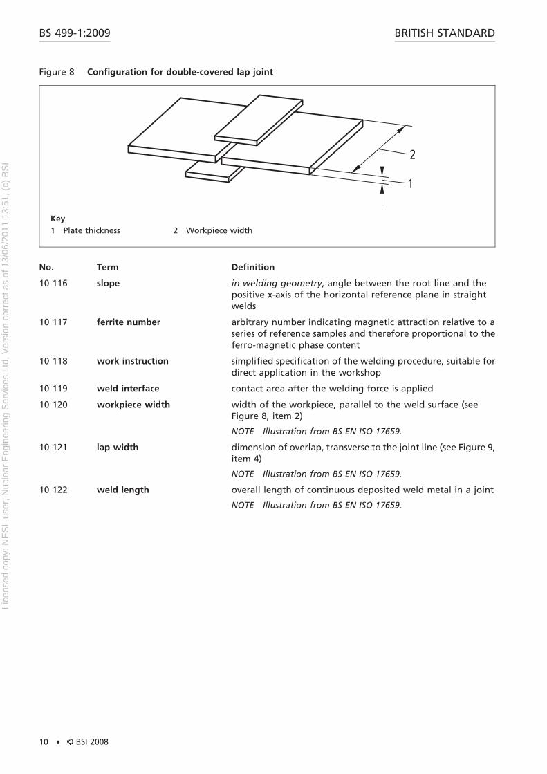
10 120 workpiece width width of the workpiece, parallel to the weld surface (seeFigure 8, item 2)
NOTE Illustration from BS EN ISO 17659.
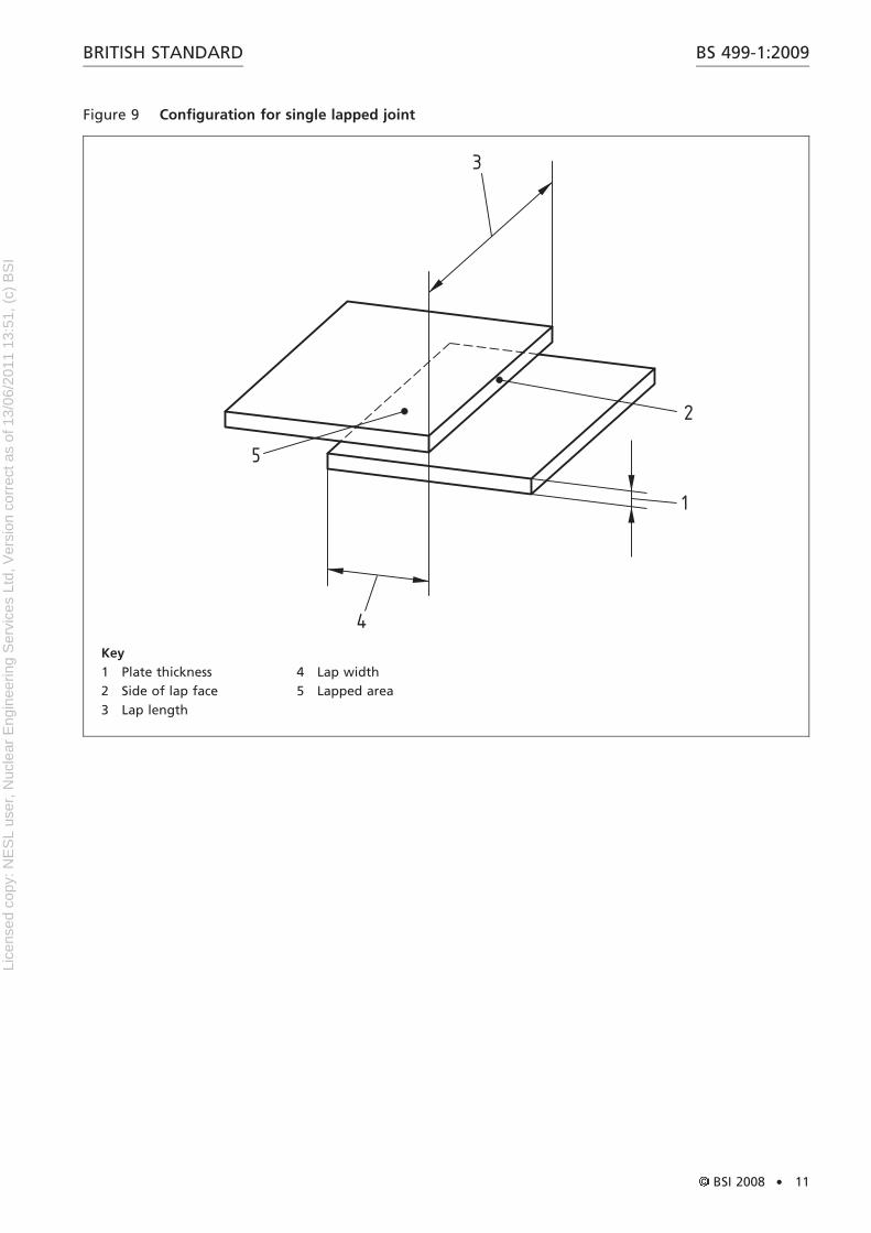
10 121 lap width dimension of overlap, transverse to the joint line (see Figure 9,item 4)
NOTE Illustration from BS EN ISO 17659.
10 122 weld length overall length of continuous deposited weld metal in a joint
NOTE Illustration from BS EN ISO 17659.
Figure 8 Configuration for double-covered lap joint
1
2
Key
1 Plate thickness 2 Workpiece width
BS 499-1:2009 BRITISH STANDARD
10 . BSI 2008
Lice
nsed
cop
y: N
ES
L us
er, N
ucle
ar E
ngin
eerin
g S
ervi
ces
Ltd,
Ver
sion
cor
rect
as
of 1
3/06
/201
1 13
:51,
(c)
BS
I
Figure 9 Configuration for single lapped joint
3
2
1
4
5
Key
1 Plate thickness
2 Side of lap face
3 Lap length
4 Lap width
5 Lapped area
BS 499-1:2009BRITISH STANDARD
BSI 2008 . 11
Lice
nsed
cop
y: N
ES
L us
er, N
ucle
ar E
ngin
eerin
g S
ervi
ces
Ltd,
Ver
sion
cor
rect
as
of 1
3/06
/201
1 13
:51,
(c)
BS
I
No. Term Definition
10 123 lap length length of lap, parallel to the joint line (see Figure 9, item 3)
NOTE Illustration from BS EN ISO 17659.
10 124 joint length dimension of joint in the direction of the weld axis (seeFigure 5, item 4, Figure 63, item 3, and Figure 65, item 2)
NOTE Illustrations from BS EN ISO 17659.
10 125 batch collection of one or more units of products, made in a singleproduction run
10 126 parent material material to be joined, or surfaced, by welding, braze weldingor brazing
10 127 contracting parties parties who have entered into a supply contract
Figure 10 Preparation for single V-butt weld
12
8
11
7
13
12
9
46143
5
10
Key
1 Plate thickness
2 Root gap
3 Depth of root face
4 Side edge of root face
5 Side edge of preparation
6 Width of preparation
7 Angle of bevel
8 Depth of preparation
9 Width of prepared face
10 Included angle
11 Fusion face (prepared)
12 Root face
BS 499-1:2009 BRITISH STANDARD
12 . BSI 2008
Lice
nsed
cop
y: N
ES
L us
er, N
ucle
ar E
ngin
eerin
g S
ervi
ces
Ltd,
Ver
sion
cor
rect
as
of 1
3/06
/201
1 13
:51,
(c)
BS
I
No. Term Definition
10 128 welding co-ordinationpersonnel
personnel who have responsibilities in the manufacturingoperation for welding and welding related activities whosecompetence and knowledge have been demonstrated by, e.g.training, education and/or relevant manufacturing experience
10 129 corrosion resistant surfacing adherent material for protection of a surface against corrosion
10 130 heat resistant surfacing adherent material for protection of a surface against heat
10 131 overlap in a lap joint, minimum distance between the edges ofoverlap platesin beam welding, portion of the weld pass remelted prior tothe slope downin seam welding, area in the preceding weld remelted by thesucceeding weld
10 132 rotation in welding geometry, angle between the centreline of a weldand the positive y-axis or a line parallel to the y-axis,measured in the counter-clockwise direction in the plane ofthe transverse cross-section of the weld
10 133 production welding welding carried out during manufacture before final deliveryto the end user
10 134 robotic welding automatic welding using a robot that can be preprogrammedto different welding paths and fabrication geometries
10 135 fully mechanized welding welding where all the main operations (excluding thehandling of the workpiece) are mechanized
NOTE Manual adjustment of welding variables during weldingis possible.
10 136 lapped area area of overlapped material in a lapped joint (see Figure 9,item 5)
NOTE Illustration from BS EN ISO 17659.
10 137 preheat maintenancetemperature
minimum temperature in the weld zone which shall bemaintained if welding is interrupted
10 138 preheating temperature temperature immediately prior to the commencement ofwelding resulting from the heating of the parent metal in theregion of the weld
10 140 finishing welding welding carried out in order to remove casting defects andcore openings to ensure the agreed quality of castings
10 142 joint welding production welding used to join components together
10 143 qualified person person whose competence and knowledge have beenobtained by education, training and/or relevant experience
NOTE In order to demonstrate the level of competence andknowledge a qualification test may be required.
10 144 heterogeneous joint welded joint in which the weld metal and parent materialhave significant differences in mechanical properties and/orchemical composition
10 145 productive welding time time during which the welding operation takes place
10 146 welding conditions conditions under which welds are made; these includeenvironmental factors (e.g. weather), stress and ergonomicfactors (e.g. noise, heat, cramped working conditions) andworkpiece-related factors (e.g. parent metal, groove shape,working position)
BS 499-1:2009BRITISH STANDARD
BSI 2008 . 13
Lice
nsed
cop
y: N
ES
L us
er, N
ucle
ar E
ngin
eerin
g S
ervi
ces
Ltd,
Ver
sion
cor
rect
as
of 1
3/06
/201
1 13
:51,
(c)
BS
I
No. Term Definition
10 147 welding parameters information needed for the performance of welding with aspecified welding procedure
NOTE Welding parameters are, e.g. welding consumables,parent material, joint preparation, welding current, weldingvoltage, travel speed, preheating, working and interpasstemperature and run sequence.
10 148 welding sequence schedule schedule specifying the order and direction in which welds areto be made on a workpiece
10 149 welding time time required for making a weld (excluding preparatory orfinishing operations)
NOTE It consists of productive welding time and the servicingtime.
10 150 joint efficiency ratio of strength of a joint to the strength of the parentmetal, expressed as a percentage
10 151 faying surfaceinterface: deprecated
1) surface of one component that is intended to be in contactwith a surface of another component to form a joint2) in friction welding, contact area developed between theworkpieces after completion of the welding operation
10 152 stud fastener to be attached by stud welding
10 153 protrusion in stud welding, distance between the tip of the stud and theface of the support device in their initial position
10 154 lift in stud welding, distance between the stud tip and theworkpiece surface with the stud-lifting mechanism in positionand activated
boundary between the fusion zone and the heat-affectedzone (See Figure 4.)
10 160 approved welding procedure documented welding procedure that has been approved bysuch means as an inspecting authority either by means of awelding procedure test or authentic documented experiencegained with the welding of joints similar to that to which thewelding procedure applies, or other approved methods
welding power source in which power is taken from all threephases of a three-phase supply to provide a single weldingcurrent or three single-phase welding currents
10 162 idling time time during which energy is available for welding but is notbeing used
BS 499-1:2009 BRITISH STANDARD
14 . BSI 2008
Lice
nsed
cop
y: N
ES
L us
er, N
ucle
ar E
ngin
eerin
g S
ervi
ces
Ltd,
Ver
sion
cor
rect
as
of 1
3/06
/201
1 13
:51,
(c)
BS
I
No. Term Definition
10 163 recovery time time required, after a change of conditions has occurred in awelding circuit, for either the current or the voltage, or both,to recover to a specific percentage of their value before thechange
10 164 cycle arbitrary unit of time, of duration equal to that of one cycle ofthe alternating current supply
NOTE Normally in the UK this is 1/50 s
10 165 nozzle-constricted arc arc that is constricted or shaped by the nozzle walls
10 166 vortex-constricted arc arc that is constricted by a vortex produced by swirling liquidor gas
10 167 transferred arc constricted arc that is struck between an electrode mountedwithin a torch and the workpiece
10 168 non-transferred arc constricted arc that is struck between an electrode within atorch and a second electrode which forms a nozzle throughwhich the plasma flows
10 169 partially transferred arc constricted arc formed when the workpiece is connected toone terminal of the power supply and the other terminal isconnected to an electrode within the torch; the torch nozzlealso forms part of the electrical circuit and is at anintermediate potential
10 170 sleeve joint joint where the ends of two pipes or round bars fit into ashort length of pipe, the inside diameter of whichapproximates to the outside diameter of the two othermembers
10 171 fixed shield independently mounted device to provide protection frominjury during welding or cutting
10 172 plain glasscover glass
clear glass or other transparent material used to protect thesurface of welding glass from spatter
10 173 welding spectacles spectacles fitted with welding glass, normally issued topersons whose duties require them to work in the vicinity ofwelding or cutting operations
10 174 welding goggles protective device enclosing a space in front of the eyes toshield them from injury during welding or cutting, fitted withwelding glass and plain glass
10 175 chipping goggles protective device enclosing a space in front of the eyes toshield them from injury during chipping, grinding or cutting,fitted with plain glass
10 176 face mask 1) protective device worn in front of the face to shield it frominjury during welding or cutting, fitted with welding glassand plain glass
2) protective device supplied with fresh air and worn over thenose and mouth
10 177 helmethead screenhead shield
protective device supported on the head and arranged toshield the face and throat from injury during welding, fittedwith a window consisting of welding glass and plain glass,and if necessary a heat filter
10 178 welding gloves gloves to protect the hands, or gauntlets to protect the handsand forearms, from heat and metal splashes due to welding orcutting
BS 499-1:2009BRITISH STANDARD
BSI 2008 . 15
Lice
nsed
cop
y: N
ES
L us
er, N
ucle
ar E
ngin
eerin
g S
ervi
ces
Ltd,
Ver
sion
cor
rect
as
of 1
3/06
/201
1 13
:51,
(c)
BS
I
No. Term Definition
10 179 open injector-mixerbunsen-type mixer
injector-mixer where the additional gas is drawn in from theatmosphere
10 180 closed injector- mixer injector-mixer that is closed to the atmosphere, the entrainedgas being drawn up through a tube connected to the unit
10 181 cone more luminous part of a flame, which is adjacent to thenozzle orifice
10 182 feather carbon-rich zone, visible in a flame, extending around andbeyond the cone when there is an excess of carbonaceous gas
10 183 gas envelope gas surrounding the inner cone of an oxy-fuel gas flame
10 184 threaded hose connection threaded part (inlet or outlet) of a welding or cuttingappliance to which a fitted hose is coupled
NOTE Threaded hose connections, hose coupling nuts and hosecouplers have right-hand threads for non-combustible gases andleft-hand threads for combustible gases. Hose coupling nuts andhose couplers having left-hand threads are notched.
10 185 hose coupling nutunion nut: deprecated
nut used for securing the hose coupling nipple to a threadedhose connection or to a hose coupler (See note to term10 184.)
10 186 hose coupling nipple metal component, one end of which is inserted into a hose,the other end has a seating and a shoulder around which canbe rotated the hose coupling nut (See note to term 10 184.)
10 187 fitted hose length of hose at each end of which is a hose coupling nippleand a hose coupling nut
10 188 hose coupler component, consisting of a hexagonal centre portion withthreaded ends, for connecting two lengths of fitted hose(See note to term 10 184.)
10 189 flame snap-out unintentional extinction of the flame outside the nozzleorifice
10 190 gas economizer auxiliary device designed for temporarily cutting off thesupply of gas to the welding equipment, except the supply toa pilot jet where fitted
10 191 two-stage regulator gas regulator in which the gas pressure is reduced to theworking pressure in two stages
10 192 manifold regulatormulti-stage regulator
gas regulator in which the gas pressure is reduced to theworking pressure in more than one stage
10 193 flame arrestorflashback arrester
safety device fitted in a fuel gas system to prevent anyflashback reaching the fuel gas pipeline or supply
10 194 hydraulic back pressure valve water-charged non-return safety valve fitted in an acetylenegas system to prevent flashback or back pressure from theblowpipe reaching the acetylene generator
10 195 flame normalizing normalizing carried out by direct flame heating
10 196 interpulse time period of time between successive pulses during the makingof a single weld
10 197 welding cyclewelding cycle time
period required to complete a welding cycle
10 198 weld timer device that controls only the weld time
device that converts single or multiphase power from thefrequency of the power supply to unidirectional current
10 200 stored-energy welding method of welding in which the welding energy is stored inan inductor, a capacitor, an electric accumulator or a flywheelduring a period of time relatively long compared to thewelding time
10 201 burnt weld weld in which the weld metal has been grossly overheatedcausing excessive oxidizing thereby reducing the strength ofthe joint
10 202 weldability ease with which a material or materials can be welded to givean acceptable joint
10 203 plasma arc transferred arc in which a constriction (mechanical ormagnetic) is used to produce a thin pencil-like configurationof plasma and electrons to give a high heat concentrationover a small area
10 204 plasma jet jet or plasma formed by a non-transferred arc and expelledthrough an orifice at high velocity by gas pressure
10 205 plasma weld surfacing surfacing or cladding in which the heat is provided by aplasma arc that may be transferred or partially transferred tothe workpiece
NOTE The cladding material may be applied as powder or asfiller wire that is fused to the parent metal.
10 206 nozzletip: deprecated
generally detachable part of a blowpipe from which gas orgases emerge
10 207 blowpipe head part of a blowpipe to which a nozzle is fitted
10 208 blowpipe shank part of a blowpipe that is normally held or gripped, to whichare fixed the valves and threaded hose connections
10 217 manipulation operation of grasping and moving an object
10 218 adaptive control systemfeedback control system
control method in which control parameters are continuouslyand automatically adjusted in response to measured processvariables to achieve the specified performance
BS 499-1:2009BRITISH STANDARD
BSI 2008 . 17
Lice
nsed
cop
y: N
ES
L us
er, N
ucle
ar E
ngin
eerin
g S
ervi
ces
Ltd,
Ver
sion
cor
rect
as
of 1
3/06
/201
1 13
:51,
(c)
BS
I
No. Term Definition
10 219 joint recognition form of adaptive control that recognizes variations in thegeometry detects changes in the joint geometry and instructsthe welding machine to take the appropriate correctiveaction
10 220 weld recognitionweld feature recognition
form of adaptive control that recognizes variations in thegeometry (including penetration depth) of the weld or weldpool being made and instructs the welding machine to takethe appropriate corrective action
10 221 joint trackingseam tracking
form of adaptive control that monitors changes in thelocation of the joint to be welded and instructs the weldingmachine to take the appropriate corrective action
10 222 forehand welding welding technique in which the welding torch or gun ispointed in the direction of welding
10 223 backhand welding welding technique in which the welding torch or gun ispointed towards the completed weld, i.e. opposite to thedirection of welding
BS 499-1:2009 BRITISH STANDARD
18 . BSI 2008
Lice
nsed
cop
y: N
ES
L us
er, N
ucle
ar E
ngin
eerin
g S
ervi
ces
Ltd,
Ver
sion
cor
rect
as
of 1
3/06
/201
1 13
:51,
(c)
BS
I
Section 2. Terms relating to welding with pressure
Subsection 21. Terms relating to more than onesubsectionNo. Term Definition
21 001 welding with pressure welding in which sufficient outer force is applied to causemore or less plastic deformation of both the faying surfaces,generally without the addition of filler metal
NOTE Usually, but not necessarily, the faying surfaces areheated in order to permit or to facilitate unifying.
21 002 interface contact area when the welding force is applied
21 003 HF induction welding welding in which an alternating electric current of at least10 kHz is induced in the work to produce heat which inassociation with a forging action produces a joint
21 004 upset metalupset
parent metal proud of the normal surfaces of the work as aresult of forging or pressing
21 005 upset allowance length allowed for the total shortening of both componentsdue to upsetting
21 006 upset speed rate of movement of the moving workpiece during upsetting
21 007 welding cycle succession of operations effected by the machine for themaking of a weld and the return to the initial position
21 008 upset force1) force producing or tending to produce upset metal
21 010 upset pressure pressure (force per unit area) resulting from the upset force
21 011 total allowance In pressure, resistance butt, flash or friction welding, thelength allowed, in preparation for welding, for the totalshortening of both components due to all the operations thatare actually used in the making of a weld
21 012 upset length total actual shortening of both components due to theforging action in the making of a weld
21 013 forging forceforge force
1) force applied normal to the faying surfaces to complete theweld2) In friction welding, force applied normal to the fayingsurfaces at the time when relative movement between thecomponents is ceasing or has ceased
21 015 forging timeforge time
duration of application of the forging force
21 016 dwell in resistance welding, maintain the electrode force after thecessation of current
21 017 dwell time in fusion welding, time during which the energy sourcepauses at any point in each oscillation
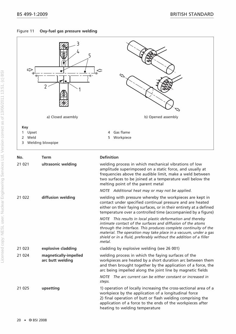
21 020 oxy-fuel gas pressurewelding
welding with pressure in which the workpieces are heated atthe faying surfaces by an oxy-fuel gas flame and the weld ismade by applying a force without addition of filler metal; theassembly may be of the open or closed type
NOTE This process is illustrated in Figure 11.
1) Force is sometimes incorrectly referred to as pressure. See terms 21 013 to 21 020.
BS 499-1:2009BRITISH STANDARD
BSI 2008 . 19
Lice
nsed
cop
y: N
ES
L us
er, N
ucle
ar E
ngin
eerin
g S
ervi
ces
Ltd,
Ver
sion
cor
rect
as
of 1
3/06
/201
1 13
:51,
(c)
BS
I
No. Term Definition
21 021 ultrasonic welding welding process in which mechanical vibrations of lowamplitude superimposed on a static force, and usually atfrequencies above the audible limit, make a weld betweentwo surfaces to be joined at a temperature well below themelting point of the parent metal
NOTE Additional heat may or may not be applied.
21 022 diffusion welding welding with pressure whereby the workpieces are kept incontact under specified continual pressure and are heatedeither on their faying surfaces, or in their entirety at a definedtemperature over a controlled time (accompanied by a figure)
NOTE This results in local plastic deformation and therebyintimate contact of the surfaces and diffusion of the atomsthrough the interface. This produces complete continuity of thematerial. The operation may take place in a vacuum, under a gasshield or in a fluid, preferably without the addition of a fillermetal.
21 023 explosive cladding cladding by explosive welding (see 26 001)
21 024 magnetically-impelledarc butt welding
welding process in which the faying surfaces of theworkpieces are heated by a short duration arc between themand then brought together by the application of a force, thearc being impelled along the joint line by magnetic fields
NOTE The arc current can be either constant or increased insteps.
21 025 upsetting 1) operation of locally increasing the cross-sectional area of aworkpiece by the application of a longitudinal force2) final operation of butt or flash welding comprising theapplication of a force to the ends of the workpieces afterheating to welding temperature
Figure 11 Oxy-fuel gas pressure welding
34
5
12
a) Closed assembly b) Opened assembly
Key
1 Upset
2 Weld
3 Welding blowpipe
4 Gas flame
5 Workpiece
BS 499-1:2009 BRITISH STANDARD
20 . BSI 2008
Lice
nsed
cop
y: N
ES
L us
er, N
ucle
ar E
ngin
eerin
g S
ervi
ces
Ltd,
Ver
sion
cor
rect
as
of 1
3/06
/201
1 13
:51,
(c)
BS
I
No. Term Definition
21 026 pressure contact area initial surface contact area of the components through whichforce is transmitted
21 027 forward force2) force applied to the movable head of a welding machine inthe direction necessary to make a weld
21 028 initial force2) first steady or peak force applied normal to the interface,during the welding cycle
21 029 welding force2)
welding load: deprecatedforce, at the abutting surfaces of a workpiece, used to make aweld
21 030 post-weld upset force2) force required to reduce the workpiece to its correct lengthafter welding
21 031 post-heating force2) force applied by the electrodes to the work during the timepost-heating current is flowing
21 032 forward pressure pressure (force per unit area) resulting from the forward force
21 033 initial pressure pressure (force per unit area) resulting from the initial force
21 034 welding pressure pressure (force per unit area) resulting from the welding force
21 035 post-weld upset pressure pressure (force per unit area) resulting from the post-weldupset force
21 036 post-heating pressure pressure (force per unit area) resulting from the post-heatingforce
21 037 overhang distance a component projects from the die or clamp in thedirection of the mating component for resistance butt, flash,friction, pressure or magnetically impelled arc butt welding
21 038 digital timer apparatus for controlling intervals of time by means ofcounting, to a preset number, pulses which have a constantrate of repetition
21 039 analogue timer apparatus for controlling intervals of time that relies uponany time dependent physical change
21 040 sequence timer apparatus comprising a group of timers for controllingvarious functions in a welding cycle in a predeterminedsequence
21 041 total loss In pressure, resistance butt, flash, friction or magneticallyimpelled arc butt welding, total amount of shortening ofboth components due to all the operations that are actuallyused in the making of a weld
21 042 forge weldingfire welding
welding with pressure in which the workpieces are heated inair in a forge and the weld is made by applying blows or someother impulsive force sufficient to cause permanentdeformation at the interfaces
2) Force is sometimes incorrectly referred to as pressure. See terms 21 032 to 21 036.
BS 499-1:2009BRITISH STANDARD
BSI 2008 . 21
Lice
nsed
cop
y: N
ES
L us
er, N
ucle
ar E
ngin
eerin
g S
ervi
ces
Ltd,
Ver
sion
cor
rect
as
of 1
3/06
/201
1 13
:51,
(c)
BS
I
Subsection 22. Terms relating only to resistance welding
No. Term Definition
22 001 resistance welding welding with pressure in which the heat necessary forwelding is produced by resistance to an electrical currentflowing through the welding zone
resistance welding in which the components are buttedtogether under pressure, and current is allowed to flow untilthe temperature is reached at which upset metal is producedand the weld is completed
22 003 flash weldingflash butt welding:deprecated
resistance welding during which heating is obtained whenthe workpieces are progressively and repeatedly advancedtowards each other, causing the current to flow throughlocalized points, thus creating flashing and expulsion ofmolten metal
22 004 spot welding resistance welding in which a weld is produced at a spot in thework-piece between electrodes, the weld being ofapproximately the same area as the electrode tips, or as thesmaller of tips of differing size; force is applied to the spot,usually through the electrodes, continuously throughout theprocess
22 005 stitch welding spot welding in which successive welds overlap
22 006 multiple spot welding spot welding in which, by the use of more than twoelectrodes, two or more welds are made simultaneously or inan automatically controlled sequence
22 007 series spot welding spot welding in which two or more welds are madesimultaneously in electrical series (See Figure 12.)
Figure 12 Examples of series spot welding
BS 499-1:2009 BRITISH STANDARD
22 . BSI 2008
Lice
nsed
cop
y: N
ES
L us
er, N
ucle
ar E
ngin
eerin
g S
ervi
ces
Ltd,
Ver
sion
cor
rect
as
of 1
3/06
/201
1 13
:51,
(c)
BS
I
No. Term Definition
22 008 seam welding resistance welding in which force is applied continuously andcurrent continuously or intermittently to produce a linearweld, the workpiece being between two electrode wheels orbetween an electrode wheel and an electrode bar; the wheelsapply the force and current and rotate continuously duringthe making of the linear weld
22 010 projection welding resistance welding in which the force and current arelocalized by the use of a projection or projections raised on orformed from one or more of the faying surfaces, theprojections collapsing during welding
22 011 resistance stud welding stud welding using projection welding(See terms 10 032 and 22 010)
22 012 percussion welding welding with pressure employing the heat from an arcproduced by a rapid discharge of electrical energy; pressure isapplied percussively during or immediately following theelectrical discharge
22 013 HF resistance welding resistance welding in which an alternating electric current ofat least 10 kHz is fed through contacts to the work to providethe heat for welding; the high frequency current concentratesalong adjacent surfaces to produce highly localized heat priorto the application of welding force
22 014 cross-wire weld resistance weld at the point of contact between crossed wiresor rods made with pressure applied continuously
22 015 resistance welding electrodeelectrode
replaceable portion of a resistance welding machine thattransmits current and applies force to the pieces to be welded
22 016 electrode shank portion of an electrode for spot or stitch welding intended tobe held by, and to make electrical contact with, an electrodeholder
22 017 electrode wheel seam welding electrode in the form of a rotating disc
22 018 flashing allowance length allowed for the total shortening of both componentsdue to flashing, in preparation for flash welding
22 020 electrode pressure pressure (force per unit of electrode contact area) resultingfrom the electrode force
22 021 flashing time3) In flash welding, period of time between the start ofcontinuous flashing and the time when the upset force isapplied
22 022 upset time3) duration of upset travel
22 023 upset current time3) time during which upset current flows
22 024 cool time3)
off-timeIn pulsation and seam welding, period of time between twosuccessive heat times in the same welding cycle
22 025 weld time3) In resistance welding, duration of continuous flow of weldingcurrent
22 026 hold time3)
dwell timeperiod of time between the cessation of current in a weldingcycle and the cessation of electrode force
22 027 welding current current (excluding preheating current) used to bring theworkpiece to, and maintain it at, welding temperature
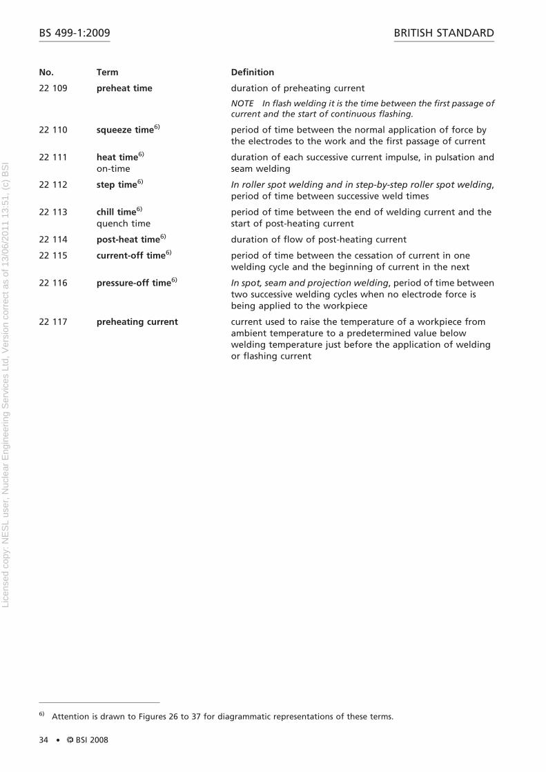
3) Attention is drawn to Figures 14 to 25 for diagrammatic representation of these terms.
BS 499-1:2009BRITISH STANDARD
BSI 2008 . 23
Lice
nsed
cop
y: N
ES
L us
er, N
ucle
ar E
ngin
eerin
g S
ervi
ces
Ltd,
Ver
sion
cor
rect
as
of 1
3/06
/201
1 13
:51,
(c)
BS
I
No. Term Definition
22 028 flashing current current flowing during flashing time
22 030 flashing travel distance travelled by the moving head during flashing
22 031 flashing speed rate of travel of the moving head during flashing
22 032 throat depththroat
in resistance welding, usable distance from the centre of theplatens or the axes of the electrodes or, in the case of obliqueelectrodes, the point of intersection of the electrode axes inthe working position or the contact line of electrode wheelsand that part of the equipment body located closest to it
22 033 throat gap 1) in spot and seam welding equipment, usable distancebetween the arms or the outer current-conducting parts ofthe welding circuit2) in projection welding equipment, clamping distancebetween the platens
22 034 indirect spot welding spot welding in which only one electrode tip is used per weld;a backing electrode or the workpiece itself completes theelectrical circuit and resists the force of the electrode tip
22 035 forge delay time period of time between the start of weld time and the instantof application of maximum welding force
22 036 backing electrode plate or strip of current-carrying material used in place of anelectrode on one side of the work to reduce the marking formulti spot, seam or projection welds
22 037 upset current current flowing during upsetting
22 038 flashing loss In flash welding, total actual shortening of both componentsduring the flashing time
22 040 flashing in flash welding, phenomenon occurring as the componentsare progressively advanced towards each other, when thecurrent, confined to localized points of contact, causesrepeated expulsion of molten metal
22 041 double-conductor connectioncable
cable comprising two conductors providing an electrical linkbetween the secondary terminals of a resistance weldingtransformer and the welding set, and designed to have as lowan electrical resistance as possible
22 042 single-conductor connectioncable
cable comprising one conductor providing an electrical linkbetween the secondary terminals of a resistance weldingtransformer and the welding set
22 043 staggered resistance welds generally spot welds in two or more rows, in a staggeredpattern (see Figure 14)
22 044 projection diameter maximum diameter of individual projection [See Figure 13a),item 4]
NOTE Illustration from BS EN ISO 17659.
BS 499-1:2009 BRITISH STANDARD
24 . BSI 2008
Lice
nsed
cop
y: N
ES
L us
er, N
ucle
ar E
ngin
eerin
g S
ervi
ces
Ltd,
Ver
sion
cor
rect
as
of 1
3/06
/201
1 13
:51,
(c)
BS
I
No. Term Definition
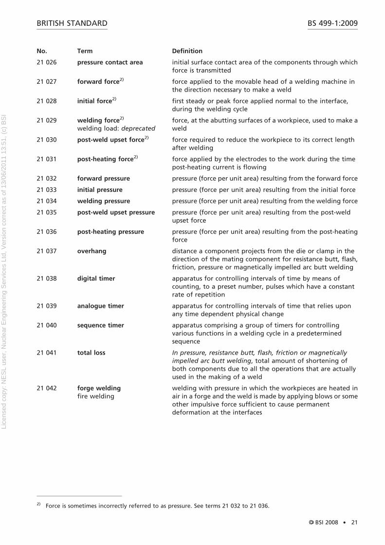
22 045 annular projection diameter mean diameter of an annular projection [See Figure 13c),item 8]
NOTE Illustration from BS EN ISO 17659.
22 046 nugget diameter in resistance spot and projection welding, mean of theminimum and maximum diameters of the fused zonemeasured at the interface omitting the corona bond area
22 047 row pitch perpendicular distance between rows of spot welds, alignedparallel to the joint axis (see Figure 14, item 4)
NOTE Illustration from BS EN ISO 17659.
Figure 13 Forms of projection welds
13
4
2
5
5
5
5
2 6
7
3
a) Round projections b) Elongated projections
3
7
85
5
2
c) Annular projections
Key
1 Plate thickness
2 Pitch (of projections)
3 Projection height
4 Projection diameter
5 Edge distance
6 Projection length
7 Projection width
8 Annular projection diameter
BS 499-1:2009BRITISH STANDARD
BSI 2008 . 25
Lice
nsed
cop
y: N
ES
L us
er, N
ucle
ar E
ngin
eerin
g S
ervi
ces
Ltd,
Ver
sion
cor
rect
as
of 1
3/06
/201
1 13
:51,
(c)
BS
I
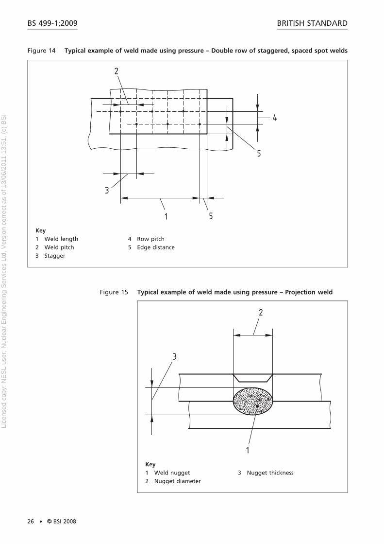
Figure 14 Typical example of weld made using pressure – Double row of staggered, spaced spot welds
1 5
5
4
2
3
Key
1 Weld length
2 Weld pitch
3 Stagger
4 Row pitch
5 Edge distance
Figure 15 Typical example of weld made using pressure – Projection weld
1
3
2
Key
1 Weld nugget
2 Nugget diameter
3 Nugget thickness
BS 499-1:2009 BRITISH STANDARD
26 . BSI 2008
Lice
nsed
cop
y: N
ES
L us
er, N
ucle
ar E
ngin
eerin
g S
ervi
ces
Ltd,
Ver
sion
cor
rect
as
of 1
3/06
/201
1 13
:51,
(c)
BS
I
No. Term Definition
22 048 pitch of projections distance between adjacent projection centres in a directionparallel to the joint line [see Figure 13a), item 2, Figure 13b),item 2, and Figure 13c), item 2].
NOTE Illustration from BS EN ISO 17659.
22 049 weld pitch In a double row of spot welds, distance between adjacentweld centres in a direction parallel to the joint line (same as‘‘stagger’’; see Figure 14, item 2)
NOTE Illustration from BS EN ISO 17659.
22 050 foil thickness thickness of foil in a foil butt seam weld (see Figure 16, item 3)
NOTE Illustration from BS EN ISO 17659.
22 051 nugget thickness maximum height of nugget in the thickness direction (seeFigure 15, item 3)
NOTE Illustration from BS EN ISO 17659.
22 052 projection height height of projection prior to welding [see Figure 13a), item 3,Figure 13b), item 3, and Figure 13c), item 3]
NOTE Illustration from BS EN ISO 17659.
22 053 indentation depression on the exterior surface or surfaces of a spot orseam weld
22 054 projection width In elongated projections, width of projection, transverse tothe joint direction [see Figure 13b), item 7]In annular projections, difference between the inner andouter radius of an annular projection [see Figure 13c), item 7]
NOTE Illustration from BS EN ISO 17659.
22 055 foil width width of foil, measured transverse to the joint axis (seeFigure 16, item 2)
NOTE Illustration from BS EN ISO 17659.
Figure 16 Foil butt-seam weld
3
4
2
4
1
Key
1 Foil length
2 Foil width
3 Foil thickness
4 Foil contact surface
BS 499-1:2009BRITISH STANDARD
BSI 2008 . 27
Lice
nsed
cop
y: N
ES
L us
er, N
ucle
ar E
ngin
eerin
g S
ervi
ces
Ltd,
Ver
sion
cor
rect
as
of 1
3/06
/201
1 13
:51,
(c)
BS
I
No. Term Definition
22 056 projection length length of an elongated projection [see Figure 13b), item 6]
NOTE Illustration from BS EN ISO 17659.
22 057 foil length length of foil, parallel to the joint axis (see Figure 16, item 1)
NOTE Illustration from BS EN ISO 17659.
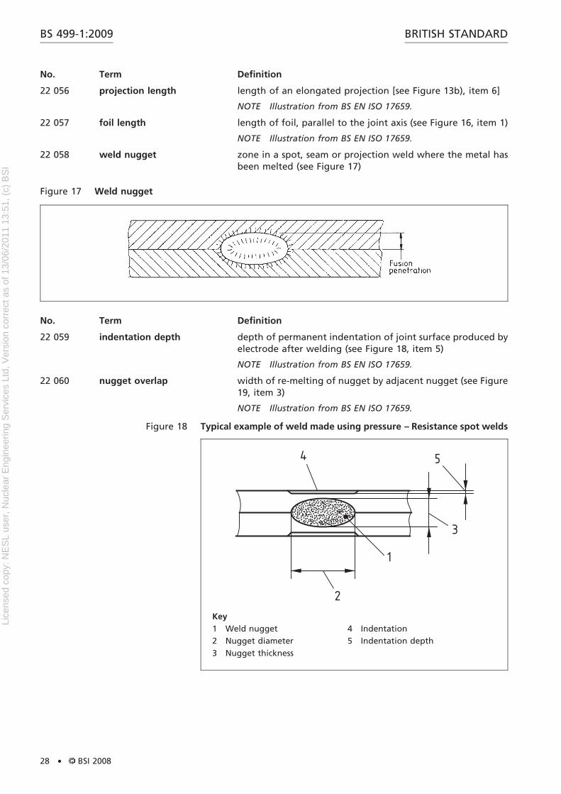
22 058 weld nugget zone in a spot, seam or projection weld where the metal hasbeen melted (see Figure 17)
No. Term Definition
22 059 indentation depth depth of permanent indentation of joint surface produced byelectrode after welding (see Figure 18, item 5)
NOTE Illustration from BS EN ISO 17659.
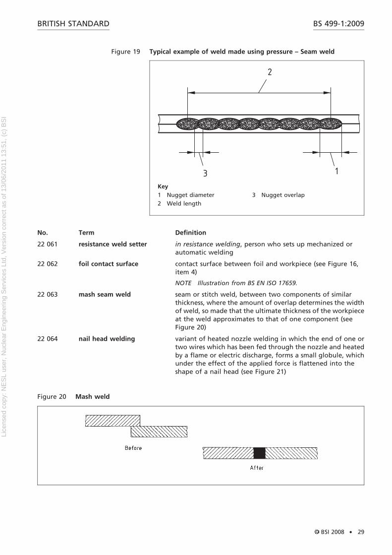
22 060 nugget overlap width of re-melting of nugget by adjacent nugget (see Figure19, item 3)
NOTE Illustration from BS EN ISO 17659.
Figure 17 Weld nugget
Figure 18 Typical example of weld made using pressure – Resistance spot welds
4
2
1
3
5
Key
1 Weld nugget
2 Nugget diameter
3 Nugget thickness
4 Indentation
5 Indentation depth
BS 499-1:2009 BRITISH STANDARD
28 . BSI 2008
Lice
nsed
cop
y: N
ES
L us
er, N
ucle
ar E
ngin
eerin
g S
ervi
ces
Ltd,
Ver
sion
cor
rect
as
of 1
3/06
/201
1 13
:51,
(c)
BS
I
No. Term Definition
22 061 resistance weld setter in resistance welding, person who sets up mechanized orautomatic welding
22 062 foil contact surface contact surface between foil and workpiece (see Figure 16,item 4)
NOTE Illustration from BS EN ISO 17659.
22 063 mash seam weld seam or stitch weld, between two components of similarthickness, where the amount of overlap determines the widthof weld, so made that the ultimate thickness of the workpieceat the weld approximates to that of one component (seeFigure 20)
22 064 nail head welding variant of heated nozzle welding in which the end of one ortwo wires which has been fed through the nozzle and heatedby a flame or electric discharge, forms a small globule, whichunder the effect of the applied force is flattened into theshape of a nail head (see Figure 21)
Figure 19 Typical example of weld made using pressure – Seam weld
2
13Key
1 Nugget diameter
2 Weld length
3 Nugget overlap
Figure 20 Mash weld
BS 499-1:2009BRITISH STANDARD
BSI 2008 . 29
Lice
nsed
cop
y: N
ES
L us
er, N
ucle
ar E
ngin
eerin
g S
ervi
ces
Ltd,
Ver
sion
cor
rect
as
of 1
3/06
/201
1 13
:51,
(c)
BS
I
No. Term Definition
22 065 straight flash welding flash welding technique in which flashing starts as soon as theworkpieces are brought into contact and is maintained untilupsetting takes place
22 066 flash welding with preheating flash welding technique in which preheating current isapplied to the workpieces to facilitate the onset of flashing
22 067 roller spot welding spot welding in which force is applied continuously andcurrent intermittently to produce a line of separate spotwelds, the workpieces being between two electrode wheelsor between an electrode wheel and an electrode bar; thewheels apply the force and current and rotate continuouslywhile the line of welds is being made
22 068 step-by-step roller spotwelding
spot welding in which force is applied continuously andcurrent intermittently to produce a line of separate spotwelds, the workpieces being between two electrode wheelsor between an electrode wheel and an electrode bar; thewheels apply the force and current and are stationary duringthe normal flow of current and rotate when reduced or nocurrent is flowing
22 069 step-by-step seam welding resistance welding in which force is applied continuously andcurrent intermittently to produce a linear weld, theworkpiece being between two electrode wheels or betweenan electrode wheel and an electrode bar; the wheels applythe force and current and are stationary during the normalflow of current and rotate when reduced or no current isflowing
Figure 21 Nail head welding
1
2
6
5
4
3
Key
1 Flame
2 Molten metal globule
3 Power source
4 Nozzle
5 Workpiece
6 Weld
BS 499-1:2009 BRITISH STANDARD
30 . BSI 2008
Lice
nsed
cop
y: N
ES
L us
er, N
ucle
ar E
ngin
eerin
g S
ervi
ces
Ltd,
Ver
sion
cor
rect
as
of 1
3/06
/201
1 13
:51,
(c)
BS
I
No. Term Definition
22 070 step-by-step welding seam or roller spot welding in which the electrode wheel isstationary during the passage of weld current and rotateswhen reduced or no current is flowing
22 071 butt-seam welding resistance welding applied progressively to a butt joint;electrodes press on the work on each side of the joint to passcurrent through it while welding force is generally applied byother means
seam welding of two close square butted components withmetal tape or wire placed or fed centrally to bridge one orboth sides of the joint (see Figure 16)
spot or projection welding in which the welding current isinterrupted one or more times without release of pressure orchange of location of the electrodes
22 074 half-cycle welding spot, projection or percussion welding in which the weldingoperation is completed in a whole or part of any one halfcycle of the a.c. supply
22 075 electrode tip surface of an electrode for spot or stitch welding intended tomake contact with the workpiece
22 076 vertical electrode electrode for spot or stitch welding in which the electrode tipis normal to the axis of the electrode shank
22 077 angle electrodeinclined electrode
electrode for spot or stitch welding in which the electrode tipis not normal to the axis of the electrode shank
22 078 offset electrode electrode for spot or stitch welding in which the electrode tipis not concentric with the axis of the electrode shank
22 079 vertical centre electrodestraight electrode
vertical electrode where the electrode tip is concentric withthe axis of the electrode shank (See Figure 22.)
22 080 vertical offset electrode vertical electrode where the electrode tip is not concentricwith the axis of the electrode shank (See Figure 23.)
No. Term Definition
22 081 angle offset electrode angle electrode in which the electrode tip is not concentricwith the axis of the electrode shank (see Figure 24)
22 082 cranked offset electrodecranked electrode
offset electrode in which the centreline of the electrode is notstraight (see Figure 25)
Figure 22 Vertical centre electrode Figure 23 Vertical offset electrode
BS 499-1:2009BRITISH STANDARD
BSI 2008 . 31
Lice
nsed
cop
y: N
ES
L us
er, N
ucle
ar E
ngin
eerin
g S
ervi
ces
Ltd,
Ver
sion
cor
rect
as
of 1
3/06
/201
1 13
:51,
(c)
BS
I
No. Term Definition
22 083 pad electrodeflat electrode
electrode having an area of contact with the work that ismuch larger than the weld required
22 084 tread peripheral surface of an electrode wheel
22 085 electrode pick-up contamination of the resistance welding electrode by metalor scale from the surface of the workpiece
22 086 surface pick-up contamination of the surface of a resistance weld by particlesof the electrode
22 087 welding diedie
device for locating the components of a workpiece in aresistance welding machine and for transmitting force andwelding current to them
22 088 insert small piece of metal, usually hard wearing and ofcomparatively high resistivity, used as an electrode tip, orattached to a welding die and projecting sufficiently beyondit to make contact with the workpiece
22 089 platen part of a resistance welding machine on which welding diesor bolsters can be mounted and which conveys force andwelding current to them
22 090 bolster electrode holder for mounting on a platen
22 091 arm member projecting from a resistance welding machine, whichcarries current, or supports a conductor carrying current, to anelectrode holder and which is required to transmit or supportthe welding force
22 092 fin extrusion of metal extending outward beyond the upsetmetal in the form of a fin
22 093 splash thin streaks of metal left adhering between the componentsor on their surfaces as the result of molten metal beingexpelled from a joint or from under the electrodes duringspot, seam, or projection welding
welding machine in which the mechanical force is applied bymeans of a pedal
22 101 power-operated weldingmachine
welding machine in which mechanical force is applied by aninanimate source of power
22 102 motor-operated weldingmachine
welding machine in which the travel of the electrode isprovided and the mechanical force is applied by means of amotor-driven mechanism
22 103 portable spot-weldingmachine
spot-welding machine:
a) that can be carried about complete, or
b) in which the electrodes, the moving arms and the forceapplication device have flexible connections to a fixedtransformer and control equipment, thus providing a limitedamount of portability
portable spot-welding machine in which force is applied toelectrodes by means of a lever system similar to that of pliers
22 105 capacitor spot-weldingmachine5)
condenser-dischargespot-welding machine
spot-welding machine in which welding current is caused toflow through the secondary winding of a transformer and thewelding electrodes by the discharging of a capacitor throughthe primary winding of the transformer
22 106 inductor spot-weldingmachine5)
induction spot-weldingmachine
spot-welding machine in which the welding current is causedto flow through the secondary winding of the transformerand the welding electrodes by the interruption of the flow ofa direct current through the primary winding of thetransformer
22 107 battery spot-weldingmachine5)
spot-welding machine in which a battery is used to providethe welding current
22 108 weld slug piece of metal pulled from one sheet when a spot orprojection weld is prised apart
NOTE The diameter of the slug may be used for weld qualityassessment.
4) Force is sometimes incorrectly referred to as pressure. See terms 22 020 and 22 098.5) These machines are sometimes referred to as ‘‘stored-energy machines’’.
BS 499-1:2009BRITISH STANDARD
BSI 2008 . 33
Lice
nsed
cop
y: N
ES
L us
er, N
ucle
ar E
ngin
eerin
g S
ervi
ces
Ltd,
Ver
sion
cor
rect
as
of 1
3/06
/201
1 13
:51,
(c)
BS
I
No. Term Definition
22 109 preheat time duration of preheating current
NOTE In flash welding it is the time between the first passage ofcurrent and the start of continuous flashing.
22 110 squeeze time6) period of time between the normal application of force bythe electrodes to the work and the first passage of current
22 111 heat time6)
on-timeduration of each successive current impulse, in pulsation andseam welding
22 112 step time6) In roller spot welding and in step-by-step roller spot welding,period of time between successive weld times
22 113 chill time6)
quench timeperiod of time between the end of welding current and thestart of post-heating current
22 114 post-heat time6) duration of flow of post-heating current
22 115 current-off time6) period of time between the cessation of current in onewelding cycle and the beginning of current in the next
22 116 pressure-off time6) In spot, seam and projection welding, period of time betweentwo successive welding cycles when no electrode force isbeing applied to the workpiece
22 117 preheating current current used to raise the temperature of a workpiece fromambient temperature to a predetermined value belowwelding temperature just before the application of weldingor flashing current
6) Attention is drawn to Figures 26 to 37 for diagrammatic representations of these terms.
BS 499-1:2009 BRITISH STANDARD
34 . BSI 2008
Lice
nsed
cop
y: N
ES
L us
er, N
ucle
ar E
ngin
eerin
g S
ervi
ces
Ltd,
Ver
sion
cor
rect
as
of 1
3/06
/201
1 13
:51,
(c)
BS
I
Fig
ure
26
Tim
ean
dp
ress
ure
dia
gra
mfo
rsi
mp
lesp
ot,
stit
ch,
or
pro
ject
ion
weld
ing
Fig
ure
27
Tim
ean
dp
ress
ure
dia
gra
mfo
rp
uls
ati
on
spo
to
rp
roje
ctio
nw
eld
ing
BS 499-1:2009BRITISH STANDARD
BSI 2008 . 35
Lice
nsed
cop
y: N
ES
L us
er, N
ucle
ar E
ngin
eerin
g S
ervi
ces
Ltd,
Ver
sion
cor
rect
as
of 1
3/06
/201
1 13
:51,
(c)
BS
I
Fig
ure
28
Tim
ean
dp
ress
ure
dia
gra
mfo
rsp
ot
or
pro
ject
ion
weld
ing
,p
rog
ram
me
con
tro
l
Fig
ure
29
Tim
ean
dp
ress
ure
dia
gra
mfo
rp
uls
ati
on
spo
to
rp
roje
ctio
nw
eld
ing
,p
rog
ram
me
con
tro
l
BS 499-1:2009 BRITISH STANDARD
36 . BSI 2008
Lice
nsed
cop
y: N
ES
L us
er, N
ucle
ar E
ngin
eerin
g S
ervi
ces
Ltd,
Ver
sion
cor
rect
as
of 1
3/06
/201
1 13
:51,
(c)
BS
I
Fig
ure
30
Tim
ean
dp
ress
ure
dia
gra
mfo
rsp
ot
weld
ing
,p
rog
ram
me
con
tro
lw
ith
du
al-
pre
ssu
recy
cle
Fig
ure
31
Tim
ean
dp
ress
ure
dia
gra
mfo
rse
am
weld
ing
BS 499-1:2009BRITISH STANDARD
BSI 2008 . 37
Lice
nsed
cop
y: N
ES
L us
er, N
ucle
ar E
ngin
eerin
g S
ervi
ces
Ltd,
Ver
sion
cor
rect
as
of 1
3/06
/201
1 13
:51,
(c)
BS
I
Fig
ure
32
Tim
ean
dp
ress
ure
dia
gra
mfo
rst
ep
-by-s
tep
seam
weld
ing
Fig
ure
33
Tim
ean
dp
ress
ure
dia
gra
mfo
rro
ller
spo
tw
eld
ing
BS 499-1:2009 BRITISH STANDARD
38 . BSI 2008
Lice
nsed
cop
y: N
ES
L us
er, N
ucle
ar E
ngin
eerin
g S
ervi
ces
Ltd,
Ver
sion
cor
rect
as
of 1
3/06
/201
1 13
:51,
(c)
BS
I
Fig
ure
34
Tim
ean
dp
ress
ure
dia
gra
mfo
rst
ep
-by-s
tep
roller
spo
tw
eld
ing
Fig
ure
35
Tim
ean
dp
late
nm
ovem
en
td
iag
ram
for
stra
igh
tfl
ash
weld
ing
BS 499-1:2009BRITISH STANDARD
BSI 2008 . 39
Lice
nsed
cop
y: N
ES
L us
er, N
ucle
ar E
ngin
eerin
g S
ervi
ces
Ltd,
Ver
sion
cor
rect
as
of 1
3/06
/201
1 13
:51,
(c)
BS
I
Fig
ure
36
Gen
era
lize
dd
iag
ram
of
speed
,ap
plied
forc
e,
axia
lm
ovem
en
tan
dti
me
for
con
tin
uo
us
dri
ve
fric
tio
nw
eld
ing
BS 499-1:2009 BRITISH STANDARD
40 . BSI 2008
Lice
nsed
cop
y: N
ES
L us
er, N
ucle
ar E
ngin
eerin
g S
ervi
ces
Ltd,
Ver
sion
cor
rect
as
of 1
3/06
/201
1 13
:51,
(c)
BS
I
Fig
ure
36
Gen
era
lize
dd
iag
ram
of
speed
,ap
plied
forc
e,
axia
lm
ovem
en
tan
dti
me
for
con
tin
uo
us
dri
ve
fric
tio
nw
eld
ing
(co
ncl
ud
ed
)
BS 499-1:2009BRITISH STANDARD
BSI 2008 . 41
Lice
nsed
cop
y: N
ES
L us
er, N
ucle
ar E
ngin
eerin
g S
ervi
ces
Ltd,
Ver
sion
cor
rect
as
of 1
3/06
/201
1 13
:51,
(c)
BS
I
Fig
ure
37
Gen
era
lize
dd
iag
ram
of
speed
,ap
plied
forc
ean
daxia
lm
ovem
en
tw
ith
tim
efo
rst
ore
den
erg
yfr
icti
on
weld
ing
BS 499-1:2009 BRITISH STANDARD
42 . BSI 2008
Lice
nsed
cop
y: N
ES
L us
er, N
ucle
ar E
ngin
eerin
g S
ervi
ces
Ltd,
Ver
sion
cor
rect
as
of 1
3/06
/201
1 13
:51,
(c)
BS
I
No. Term Definition
22 118 post-heating current current that is passed through a completed weld to heat it,usually for metallurgical reasons
22 119 dual-pressure cycle welding cycle characterized by the application of twodifferent predetermined electrode forces
22 120 programme control method of controlling a predetermined sequence of changesof current and/or force during a welding cycle
22 121 heat control means of smoothly controlling the value of the currentflowing through a resistance welding machine
22 122 constant current control electronic control of the value of welding current, to make itspreset value constant and independent of variations in eithermains voltage or the amount of magnetic material introducedinto the throat of the welding machine
22 123 synchronous control electronic control system that ensures that the instant ofclosing the circuit to a resistance welding transformer isalways at a preset electrical angle to the instant of zerovoltage of the a.c. supply
22 124 non-synchronous control control system that does not ensure that the instant of closingthe circuit to a resistance welding transformer is repetitivelyat the same instantaneous voltage of the a.c. supply
22 125 phase shift alteration of the phase relationship between two a.c. voltages
NOTE Generally this is used to control the period of conductionin each half cycle of ignitron or thyristor contactors.
22 126 phase anglefiring angle
electrical angle between the instantaneous zero voltageapplied to the anode of an ignitron or thyristor and the pointat which it conducts in each half cycle
22 127 slope control control of the rate of rise or decay of current and the timeduring which either takes place in the power circuit of aresistance welding machine
NOTE This should not be confused with term 32 129.
22 128 rate of slope rate of change of current when using slope control
22 129 slope time duration of slope-up or slope-down
22 130 upset travel 1) In resistance butt welding. distance travelled by the movingplaten in forging a weld from the point where thecomponents are first brought together to the position wherethe weld is completed
2) In flash welding. distance travelled by the moving platen inforging a weld from the point where the components havebeen brought together at the end of flashing to the positionwhere the weld is completed
22 131 preheating loss total loss of length of both components during preheating aflash weld
22 132 machine stroke maximum operational stroke obtainable
22 133 operational stroke distance through which the electrode(s) may travel from restto the final position during welding
22 134 die openingdie gap
In a flash or resistance butt welding machine, distancebetween the opposing faces of the two pairs of dies when themachine is set up for welding
22 135 clamp opening distance between the jaws of a clamp in the open position,through which the workpiece would be inserted or withdrawn
BS 499-1:2009BRITISH STANDARD
BSI 2008 . 43
Lice
nsed
cop
y: N
ES
L us
er, N
ucle
ar E
ngin
eerin
g S
ervi
ces
Ltd,
Ver
sion
cor
rect
as
of 1
3/06
/201
1 13
:51,
(c)
BS
I
No. Term Definition
22 136 wearing depth length or thickness of material that may be worn or dressedoff the working surface of an electrode or die before itbecomes unserviceable
22 137 parallel spot welding spot welding in which the secondary current of the weldingtransformer is fed to two or more pairs of welding electrodesconnected in parallel
22 138 push-pull series spot welding series spot welding using two pairs of electrodes and twotransformers so that a transformer is connected to the top andbottom electrodes respectively thereby putting all in electricalseries
22 139 unipolarity operationunipolarity welding
resistance welding in which succeeding welds are made withpulses of the same polarity
resistance welding in which succeeding welds are made withpulses of opposite polarity
22 141 pre-weld time period of time between the end of squeeze time and thebeginning of welding current flow
22 142 post-weld time period of time between the end of welding current flow andthe start of hold time
22 143 weld delay time time by which the beginning of welding current flow isdelayed with respect to the initiation of the forge delay timerin order to synchronize the welding force with the weldingcurrent flow
22 144 weld heat time In welding with slope control, period of time between thebeginning of slope-up and the cessation of steady current orthe start of slope-down
22 145 weld interval heat time weld heat time as applied to pulsation welding
22 146 decay time time during which decaying of a current takes place
22 147 decay current current, applied to the primary of a three-phase frequencyconversion welding machine transformer at a level below thewelding current, that determines the decay time and rate ofdecay
22 148 current decay current that decreases from an initial preset value to a finalpreset value at a rate depending upon the time constant ofthe circuit
22 149 electronic frequencyconverter
electronic device that converts the welding power from thefrequency of the power supply to a different value
22 150 two-stage initiation method of operation in which closure of the first stage of theinitiation switch initiates the electrode force and closure ofthe second stage initiates the remainder of the welding cycle
NOTE The closure of the second stage may, or may not,immediately follow the closure of the first stage. The first stage isnon-beat after closing the second stage. The second stage is notcapable of being initiated if the first stage is open.
22 151 repeat operation method of operation in which once the weld cycle has beeninitiated it is repeated until the initiation switch is opened
22 152 non-repeat operationsingle operation
method of operation in which each initiation of the initiationswitch provides one welding cycle only
22 153 non-beat type of system that prevents any interruption of the weldingcycle once the initiation switch has been operated
BS 499-1:2009 BRITISH STANDARD
44 . BSI 2008
Lice
nsed
cop
y: N
ES
L us
er, N
ucle
ar E
ngin
eerin
g S
ervi
ces
Ltd,
Ver
sion
cor
rect
as
of 1
3/06
/201
1 13
:51,
(c)
BS
I
No. Term Definition
22 154 delayed non-beat type of system which permits the interruption of the weldingcycle only up to the end of squeeze time
22 155 gun welding headgun
force-producing and electrode-carrying assembly of a gunwelding machine
22 156 dual gun control method of control in which the welding cycle from onecontroller can be switched to either of two gun weldingheads supplied from one transformer
method of control in which the welding cycle to each of thegun welding heads supplied from one transformer can becontrolled independently, the initiation circuit beinginterlocked to allow the operation of only one gun at a time
22 158 delayed firing delayed initiation of the welding current in the first half cyclein order to minimize the initial transient of magnetizingcurrent of the welding transformer
22 159 cascade firingsequence firing: deprecated
In multi-weld applications, system of switching in which eachtransformer or group of transformers is switched insuccession, with or without current-off time during switching
NOTE This system may be used to limit the supply load.
22 160 electrode face surface of an electrode that makes contact with theworkpiece
22 161 back plate plate to which two or more bolsters can be bolted to holdthem in their correct relative positions
22 162 back-up die die into which may be inserted a number of removable insertsor electrodes
22 163 angle centre electrode angle electrode in which the electrode tip is concentric withthe electrode shank (see Figure 38)
cranked offset electrode with a second bend (see Figure 39)
22 165 averaging time time that is the sum of the maximum allowable conducting(on) time at maximum current and the minimum safe off timein a duty cycle for equipment which may be damaged by anythermal overload
Figure 38 Angle centre electrode Figure 39 Swan-necked electrode
BS 499-1:2009BRITISH STANDARD
BSI 2008 . 45
Lice
nsed
cop
y: N
ES
L us
er, N
ucle
ar E
ngin
eerin
g S
ervi
ces
Ltd,
Ver
sion
cor
rect
as
of 1
3/06
/201
1 13
:51,
(c)
BS
I
No. Term Definition
22 166 welding pressure time period during which the welding force is maintained in themaking of a weld
22 167 post-heating pressure time duration of electrode pressure associated with any post-heattreating cycle
22 168 head lowering time period from the instant the electrode leaves the ‘‘at rest’’position between successive welds to the instant of touchingthe workpiece
22 169 pressure application time total time in any one welding cycle of the application of forceby the electrodes to the workpiece
22 170 pressure decrease time time taken for the force applied by the electrodes to the workto change from one steady value to a lower steady value or tozero
22 171 touch time one period when two parts to be welded are in contactduring reciprocating preheating for flash welding
22 172 heat diffusion time one period when two parts to be welded are separated andno current is flowing between them during reciprocatingpreheating for flash welding
22 173 initial current steady value of current applied before the commencement ofslope-up in welding with slope control
22 174 final current final steady value of current at the end of the slope-downperiod of a welding cycle
22 175 phase displacement alteration of the phase relationship of two alternatingelectrical functions so that they do not pass through zero atthe same time
22 176 cycle counter electronic or electromechanical device for counting thenumber of cycles during a period of flow of an alternatingcurrent
22 177 cycle recorder electronic or electromechanical device for recording, on paperor film, the number of cycles during a period of flow of analternating current
22 178 modulator electromechanical device to control the value of currentduring the heat and cool times in seam welding
22 179 multi-pressure cycle welding in which more than one steady value of electrodeforce is used during any one welding cycle
22 180 high lift system arrangement whereby the maximum electrode clearance forinsertion and withdrawal of the workpiece is much greaterthan the operational stroke
22 181 electrode gapelectrode clearance
distance between two corresponding electrode faces whenthe machine is ready for operation
22 182 follow-up movement of an electrode assembly that keeps the electrodeforce applied while surface indentation or collapse isoccurring on the workpiece
22 183 preheating allowance In flash welding, length allowed for the total shortening ofboth components due to a preheating operation
22 184 push gunpoke gun
gun welding head with which the welder applies the weldingforce by direct manual pushing
BS 499-1:2009 BRITISH STANDARD
46 . BSI 2008
Lice
nsed
cop
y: N
ES
L us
er, N
ucle
ar E
ngin
eerin
g S
ervi
ces
Ltd,
Ver
sion
cor
rect
as
of 1
3/06
/201
1 13
:51,
(c)
BS
I
No. Term Definition
22 185 expansion gunreaction gun
gun welding head that can be used between a workpiece anda fixed member and which derives the welding force bylongitudinal expansion
22 186 rocker arm moveable arm of a welding machine which is pivotedapproximately centrally and is pushed upward at one end tobring down the end that carries the moving electrode intocontact with the fixed electrode
22 187 rotary welding transformer transformer for a butt-seam welding machine that isconnected solidly to the wheel electrodes and rotates withthem, while the primary current at mains voltage is led inthrough slip rings
22 188 welding pressure headpressure head
assembly of those parts of a welding machine that producethe force required for welding
22 189 electrode wheel head part of a seam welding machine that carries the electrodewheel that is lowered and raised to and from the workpiece
22 190 weld-through sealer mastic gap-filling material that is applied prior to resistancewelding to an unpainted metal surface for non-pressuresealing purposes and does not prevent the making of asatisfactory weld
Subsection 23. Terms relating only to friction welding
No. Term Definition
23 001 friction welding welding with pressure in which the interfaces are heated byfriction by relative movement of the joint faces, normally byrotating one or both workpieces in contact with each other orby means of a separate rotating friction element; the weld iscompleted by an upset force, generally after rotation hasceased (see Figure 36 and Figure 37)
23 002 friction force force(s) applied normal to the faying surfaces during the timethat there is relative movement between the components
23 003 friction pressure pressure (force per unit area) on the faying surfaces resultingfrom the friction force
23 004 friction speed rate of relative movement of the components
23 005 friction time time during which relative movement between thecomponents takes place at friction speed and underapplication of the friction force
23 006 forging speed in friction welding, relative velocity of the workpieces at theinstant the forge force is applied
23 007 burn-off length overall length loss of the components during the applicationof the friction force
23 008 flash metal extruded during friction welding
23 009 friction stir welding friction welding where heat is generated by friction betweena rotating non-consumable spindle and stationary workpieces(see Subsection 27)
23 010 friction welding forge force longitudinal force applied to the faying surfaces at the timewhen relative movement between the components is ceasingor has ceased
BS 499-1:2009BRITISH STANDARD
BSI 2008 . 47
Lice
nsed
cop
y: N
ES
L us
er, N
ucle
ar E
ngin
eerin
g S
ervi
ces
Ltd,
Ver
sion
cor
rect
as
of 1
3/06
/201
1 13
:51,
(c)
BS
I
No. Term Definition
23 011 forging pressureforge pressure
pressure (force per unit area) resulting from the forging force
23 012 forge length amount by which the overall length of the components isreduced during the application of the forge force
23 013 forge rate rate of shortening of the components during the applicationof the forge force
23 014 stopping time time required by the moving component to decelerate fromfriction speed to zero speed
Subsection 24. Terms relating only to pressure welding
No. Term Definition
24 001 pressure weldingsolid-phase welding
welding process in which a weld is made by a sufficientpressure to cause plastic flow of the surfaces, which may ormay not be heated
24 002 HF pressure welding pressure welding in which heat derived from a high frequencyalternating electric current of at least 10 kHz, induced orconducted into the workpiece, is used to make plastic thesurfaces to be united
24 003 oxy-acetylene pressurewelding
pressure welding in which an oxy-acetylene flame is used tomake plastic the surfaces to be united
NOTE Other fuel gases are sometimes used and in such casesappropriate alterations to the term and the definition arenecessary.
24 004 constant-pressurepressure welding
pressure welding in which the weld is made during the periodof increasing temperature at a substantially constant pressure
24 005 constant-temperaturepressure welding
pressure welding in which the weld is made during theapplication of increasing pressure at a substantially constanttemperature
24 006 cold pressure welding pressure welding in which pressure alone is used
24 007 heating time in constant-temperature pressure welding, time during whichthe parts are heated before the application of the upsettingforce
24 008 upsetting time In constant-temperature pressure welding, time during whichthe parts to be joined are maintained at the weldingtemperature and under the upsetting force
24 009 welding time sum of the heating time and the upsetting time
24 010 deformation local percentage reduction in the total thickness of sheets orplates at a pressure-welded lap joint
Subsection 25. Terms relating only to diffusion welding
No. Term Definition
25 001 diffusion welding joining process wherein all the faces to be welded are heldtogether by a pressure insufficient to cause readily detectableplastic flow, at a temperature below the melting point of anyof the parts, the resulting solid state diffusion, with or withoutthe formation of a liquid phase, causing welding to occur
BS 499-1:2009 BRITISH STANDARD
48 . BSI 2008
Lice
nsed
cop
y: N
ES
L us
er, N
ucle
ar E
ngin
eerin
g S
ervi
ces
Ltd,
Ver
sion
cor
rect
as
of 1
3/06
/201
1 13
:51,
(c)
BS
I
No. Term Definition
25 002 solid state diffusion welding diffusion welding in which all the reactions occur in the solidstate
25 003 liquid phase diffusionwelding
diffusion welding in which solid state interdiffusion betweendissimilar materials results in the formation of a liquid phase
Subsection 26. Terms relating only to explosive welding
No. Term Definition
26 001 explosive welding pressure welding process to make lap joints or cladding inwhich the overlapping workpieces are welded when impactedtogether by the detonation of an explosive charge
26 002 parent plate;static plate
stationary plate in a lap joint or plate to be clad
26 003 flyer plate moving plate in a lap joint or the cladding to be applied tothe parent plate
26 004 anvil support on which the parent plate rests
26 005 buffer solid material placed between the explosive and the flyerplate to transmit the explosive force and to protect the flyerplate
26 006 initial plate angleinitial inclination
angle of inclination between the flyer plate and the parentplate before welding
26 007 collision anglecontact angle
angle of inclination between the flyer plate and the parentplate during welding
26 008 stand-off distancestand-off gap
distance between the plates in a parallel assembly
26 009 collision front three-dimensional line of collision points or lines of contact
26 010 jet air, expelled from between the plates during the explosion,which cleanses the two surfaces to be joined
26 011 shocked metal zone parts of the plates that are metallurgically affected by theimpact
26 012 blending taper conically prepared end of a tube usually for tube totube-plate welding
26 013 distortion plugdistortion bung
plugs inserted into vacant holes of a tube-plate to prevent thedistortion of the ligament by welds carried out in the adjacentholes
Subsection 27. Terms relating only to friction stirwelding
No. Term Definition
27 001 tool rotating component that includes the shoulder and probe(see Figure 40)
27 002 probe part of the tool that extends into the workpiece to make theweld (see Figure 40 and Figure 41)
NOTE The probe can be either fixed or adjustable.
27 003 z-direction direction parallel to the tool axis (see Figure 40)
BS 499-1:2009BRITISH STANDARD
BSI 2008 . 49
Lice
nsed
cop
y: N
ES
L us
er, N
ucle
ar E
ngin
eerin
g S
ervi
ces
Ltd,
Ver
sion
cor
rect
as
of 1
3/06
/201
1 13
:51,
(c)
BS
I
27 004 x-direction direction parallel to the direction of travel in the plane of theworkpiece (see Figure 40)
27 005 y-direction direction normal to the direction of travel in the plane of theworkpiece (see Figure 40)
Figure 40 Basic principle of friction stir welding
14
3
2
7
8
5
6
XY
Z
Key
1 Workpiece
2 Tool
3 Probe
4 Shoulder
5 Advancing side of weld
6 Retreating side of weld
7 Weld surface
8 Exit hole
Figure 41 Macrosection of a butt weld showing incomplete penetration
Key
1 Workpiece
2 Probe
3 Original joint line – no deformation
4 Original joint line – severely plastically deformed
1
2
4
3
BS 499-1:2009 BRITISH STANDARD
50 . BSI 2008
Lice
nsed
cop
y: N
ES
L us
er, N
ucle
ar E
ngin
eerin
g S
ervi
ces
Ltd,
Ver
sion
cor
rect
as
of 1
3/06
/201
1 13
:51,
(c)
BS
I
No. Term Definition
27 006 fixed probe probe that has a fixed length protruding from the shoulderand its rotation is the same as the shoulder during welding
27 007 shoulder surface of the tool that contacts the workpiece duringwelding (see Figure 40 and Figure 42)
27 008 adjustable probe tool probe that has adjustable length and its rotation may bedifferent from the shoulder during welding (see Figure 43)
NOTE 1 An adjustable probe may be used as a fixed probe.
NOTE 2 This tool enables joining to be accomplished withoutcreating excessive toe flash at the start, or an exit hole at thefinish.
27 009 heel part of the tool shoulder that is at the rear of the tool relativeto its forward motion (see Figure 42)
Figure 42 Heel and heel plunge depth
Key
1 Workpiece
2 Probe
3 Shoulder
4 Heel
5 Heel plunge depth
6 Rotary motion
7 Down force
8 Tilt angle
9 Direction of travel
7 8
3
1
6
5
42
9
Figure 43 Adjustable probe tool
1
2
Key
1 Workpiece 2 Adjustable probe tool
BS 499-1:2009BRITISH STANDARD
BSI 2008 . 51
Lice
nsed
cop
y: N
ES
L us
er, N
ucle
ar E
ngin
eerin
g S
ervi
ces
Ltd,
Ver
sion
cor
rect
as
of 1
3/06
/201
1 13
:51,
(c)
BS
I
No. Term Definition
27 010 fixed bobbin tool tool with two shoulders separated by a fixed length probe(see Figure 44)
27 011 self-reacting bobbin tool tool with two shoulders separated by a probe whose lengthcan be adjusted during welding (see Figure 45)
NOTE The self-reacting bobbin tool allows the shoulders toautomatically maintain contact with the workpiece.
Figure 44 Fixed bobbin tool
Key
1 Workpiece
2 Bobbin tool
3 Upper shoulder
4 Probe
5 Lower shoulder
1
2
3
45
Figure 45 Self-reacting bobbin tool
Key
1 Workpiece
2 Top shoulder
3 Probe
4 Bottom shoulder
5 Reactive forces
2
1
6
3
54
BS 499-1:2009 BRITISH STANDARD
52 . BSI 2008
Lice
nsed
cop
y: N
ES
L us
er, N
ucle
ar E
ngin
eerin
g S
ervi
ces
Ltd,
Ver
sion
cor
rect
as
of 1
3/06
/201
1 13
:51,
(c)
BS
I
No. Term Definition
27 012 position control method to provide the required position of the tool duringwelding
27 013 lateral offset distance from the tool axis to the root face
27 014 tilt angletravel angle
angle between the normal to the plane of the workpiecesurface and the tool axis measured in the Z-X plane of travelof the tool axis (see Figure 42)
27 015 sideways tilt anglework angle
angle between the normal to the plane of the workpiecesurface and the tool axis measured in the Z-Y plane normal tothe direction of travel of the tool
27 016 tool plunge depth inserting the tool into the workpiece in order to make a weld
27 017 heel plunge depth distance the heel extends into the parent material (seeFigure 42)
27 018 advancing side side of the weld where the direction of tool rotation is thesame as the welding direction (see Figure 40)
27 019 retreating side side of the weld where the direction of tool rotation isopposite to the welding direction (see Figure 40)
27 020 force control method to provide the required force on the tool duringwelding
27 021 down forcetraversing forcez-force
axial force applied in the z-direction by the tool to theworkpiece during welding in the x-direction (see Figure 42)
27 022 sideways forcey-force
Force experienced in the y-direction by the tool to theworkpiece during welding in the x-direction
27 023 traversing forcex-force
force applied in the x-direction by the tool to the workpieceduring welding in the x-direction
In friction stir welding, distance travelled by the probe axis, ina direction parallel to the joint axis, per unit time
NOTE No account is taken of any lateral oscillation of the probeaxis.
27 025 dwell time at start of weld time interval between when the rotating tool reaches itsmaximum depth in the parent material and the start of travel
27 026 dwell time at end of weld time interval after travel has stopped but before the rotatingtool has begun to withdraw from the weld
27 027 heat affected zoneHAZ
area affected only by heat with no visible macroplasticdeformation detectable by using optical microscopy (seeFigure 46)
27 028 thermomechanically affectedzoneTMAZ
area affected by both heat and macroplastic deformation (seeFigure 46)
27 029 nugget part of the TMAZ where the microstructure has been subjectto recrystalization (see Figure 46)
NOTE In most aluminium alloys, the nugget is bounded byunrecrystalized TMAZ. In many other alloys, the nugget extendsmost or all of the TMAZ, and possibly into the HAZ.
BS 499-1:2009BRITISH STANDARD
BSI 2008 . 53
Lice
nsed
cop
y: N
ES
L us
er, N
ucle
ar E
ngin
eerin
g S
ervi
ces
Ltd,
Ver
sion
cor
rect
as
of 1
3/06
/201
1 13
:51,
(c)
BS
I
No. Term Definition
27 030 exit hole hole remaining at the end of a weld after the withdrawal ofthe tool (see Figure 40 and Figure 47)
27 031 shoulder footprint partially or fully formed ring surrounding the exit hole (seeFigure 47)
No. Term Definition
27 032 flash imperfection consisting of excessive metal protrudingupwards at the weld toe
27 033 underfill depression resulting when the weld face is below the adjacentparent material surface
27 034 incomplete penetration imperfection where the full thickness of the joint has notbeen welded (see Figure 41)
Figure 46 Cross-section of a friction stir weld
1 2 3 4(+3) 3 2 1
Key
1 Parent material
2 Heat affected zone (HAZ)
3 Thermomechanically affected zone (TMAZ)
4 Nugget
Figure 47 Tool shoulder footprint visible at the exit hole
Key
1 Workpiece
2 Shoulder footprint
3 Exit hole
4 Weld surface
2
4
3
1
BS 499-1:2009 BRITISH STANDARD
54 . BSI 2008
Lice
nsed
cop
y: N
ES
L us
er, N
ucle
ar E
ngin
eerin
g S
ervi
ces
Ltd,
Ver
sion
cor
rect
as
of 1
3/06
/201
1 13
:51,
(c)
BS
I
No. Term Definition
27 035 voidvolumetric flaw
non-planar discontinuity in the TMAZ which may be buried orsurface breaking
NOTE The extent may be classified as continuous, sporadic,isolated or clustered, fine, coarse, etc.
27 036 joint line remnant imperfection consisting of a semi-continuous layer of oxide inthe weld
NOTE The severity of this imperfection depends upon its extentand the proximity of the adjacent oxide particles. Joint lineremnants can have some effect on the mechanical performanceof the joint.
27 037 kissing bond weakly bonded joint line remnant in the root region, oftendifficult to detect non-destructively
27 038 hook curved notch on the advancing side of the lap weld (seeFigure 48, T3)
27 039 lap joint sheet thinning workpiece thickness minus the distance from the weld face tothe end of the hook (see Figure 48)
NOTE In Figure 48, the sheet thinning in the lap joint is T1 – T2
or T1 – T3.
BS 499-1:2009BRITISH STANDARD
BSI 2008 . 55
Lice
nsed
cop
y: N
ES
L us
er, N
ucle
ar E
ngin
eerin
g S
ervi
ces
Ltd,
Ver
sion
cor
rect
as
of 1
3/06
/201
1 13
:51,
(c)
BS
I
Figure 48 Cross-section of friction stir lap weld showing undesirable/extreme plate thinning on theretreating side and a hook feature on the advancing side of the weld
a) Upper plate thinning
Key
T1 Sheet thickness
T2 Retreating side, sheet thickness
T3 Advancing side, sheet thickness
b) Lower plate thinning
c) Ideal situation
Key
1 Upper workpiece
2 Lower workpiece
3 Retreating side, notch tip orientation awayfrom shoulder side
4 Advancing side, notch tip orientation away fromshoulder side
5 Retreating side, notch tip abrupt end
6 Advancing side, notch tip abrupt end
T 1
T 2 T 3
1
2 3 4
2
1
5 6
BS 499-1:2009 BRITISH STANDARD
56 . BSI 2008
Lice
nsed
cop
y: N
ES
L us
er, N
ucle
ar E
ngin
eerin
g S
ervi
ces
Ltd,
Ver
sion
cor
rect
as
of 1
3/06
/201
1 13
:51,
(c)
BS
I
Section 3. Terms relating to fusion welding (weldingwithout pressure)
Subsection 31. Terms relating to more than onesubsection
No. Term Definition
31 001 fusion welding welding without application of external force in which thefaying surface(s) has (have) to be molten; usually, but notnecessarily, molten filler metal is added
31 002 back-step sequence welding sequence in which short lengths of run are depositedin a direction opposite to the general progress of welding thejoint (see Figure 49)
No. Term Definition
31 003 back-step welding welding following a back-step sequence
31 004 continuous weld weld extending along the entire length of a joint
31 005 intermittent weld series of welds of the same type and dimensions at intervalsalong a joint
31 006 butt weld 1) In a butt joint. weld between two parts making an angle toone another of 135º to 180º inclusive in the region of the weldsuch that a line parallel to a surface of one part, perpendicularto the line of the joint, and passing through the centre of thefusion face of that part, passes through the fusion face of theother part (see Figure 50.1 to Figure 50.11, Figure 50.13,Figure 50.15 and Figure 50.16)2) In a T-joint. weld between two parts making an angle toone another of 45º to 90º inclusive in the region of the weldsuch that a line parallel to a surface of one part, perpendicularto the line of the joint, and passing through the centre of thefusion face of that part, passes through the fusion face of theother part (see Figure 50.19, Figure 50.21, Figure 50.23 andFigure 50.24)3) In a corner joint. weld between two parts making an angleto one another of 45º to 135º inclusive in the region of theweld such that a line parallel to a surface of one part,perpendicular to the line of the joint, and passing throughthe centre of the fusion face of that part, passes through thefusion face of the other part (see Figure 50.32)
Figure 49 Example of back-step sequence
BS 499-1:2009BRITISH STANDARD
BSI 2008 . 57
Lice
nsed
cop
y: N
ES
L us
er, N
ucle
ar E
ngin
eerin
g S
ervi
ces
Ltd,
Ver
sion
cor
rect
as
of 1
3/06
/201
1 13
:51,
(c)
BS
I
No. Term Definition
31 007 square butt weld butt weld in the preparation for which the fusion faces lieapproximately at right angles to the surfaces of thecomponents to be joined and are substantially parallel to oneanother (see Figure 50.1 to Figure 50.6)
31 008 single-V butt weld butt weld in the preparation for which the edges of bothparts are bevelled so that in cross section the fusion faces forma V (see Figure 50.7 to Figure 50.9)
31 009 staggered intermittent weld intermittent weld on each side of a joint (usually fillet weldsin T and lap joints) arranged so that the welds on one side lieopposite to the spaces on the other side along the joint
31 010 double-V butt weld butt weld in the preparation for which the edges of bothcomponents are double bevelled so that in cross section thefusion faces form two opposing V s (see Figure 50.10,Figure 50.11 and Figure 50.13)
31 011 single-U butt weld butt weld in the preparation for which the edges of bothcomponents are prepared so that in cross section the fusionfaces form a U
Figure 50 Sketches of types of joints, types of weld(s) and weld preparations
Figureno.
Sketch Type ofjoint
Type ofweld(s)
Preparation Remarks
50.1 Butt Butt Close square Full penetration
50.2 Butt Butt Close square Full penetration
50.3 Butt Butt Raised edges —
50.4 Butt Butt Close square Partialpenetration
50.5 Butt Butt Open squarewith backingbar
Full penetration
50.6 Butt Butt Close square Full penetration.Welded fromboth sides
50.7 Butt Butt Single-Vwith rootfaces.
Full penetration
50.8 Butt Butt Single-Vwith backingstrip
Full penetration
50.9 Butt Butt Single-Vwith rootfaces
Full penetration.Sealing run used
BS 499-1:2009 BRITISH STANDARD
58 . BSI 2008
Lice
nsed
cop
y: N
ES
L us
er, N
ucle
ar E
ngin
eerin
g S
ervi
ces
Ltd,
Ver
sion
cor
rect
as
of 1
3/06
/201
1 13
:51,
(c)
BS
I
Figure 50 Sketches of types of joints, types of weld(s) and weld preparations (continued)
Figureno.
Sketch Type ofjoint
Type ofweld(s)
Preparation Remarks
50.10 Butt Butt Double-Vwith rootfaces
Full penetration.Welded fromboth sides
50.11 Butt Butt Double-Vwith broadroot faces
Partialpenetration.Welded fromboth sides
50.12 Butt Butt andfillet
Single-Vwith broadroot faces
Partialpenetration.Welded fromboth sides
50.13 Butt Butt Double-Vwith rootfaces
Full penetration.Welded fromboth sides
50.14 Butt Fillet Close square Welded fromboth sides
Figure 50 Sketches of types of joints, types of weld(s) and weld preparations (continued)
Figureno.
Sketch Type ofjoint
Type ofweld(s)
Preparation Remarks
50.20 T Fillet Close square Welded fromboth sides
50.21 T Butt Double-bevel
Full penetration.Welded fromboth sides
50.22 T Compoundof butt andfillets
Double-bevel
Full penetration.Welded fromboth sides
50.23 T Butt Double-bevel withwide or deeproot face
Partialpenetration.Welded fromboth sides
50.24 T Butt Single-bevel Full penetration
50.25 T Fillet Edgeprepared asnecessary
—
50.26 Cruciform Butt Double-bevel
Welded fromboth sides
50.27 Cruciform Fillet Close square Welded fromboth sides
50.28 Lap Fillet Square edge —
BS 499-1:2009 BRITISH STANDARD
60 . BSI 2008
Lice
nsed
cop
y: N
ES
L us
er, N
ucle
ar E
ngin
eerin
g S
ervi
ces
Ltd,
Ver
sion
cor
rect
as
of 1
3/06
/201
1 13
:51,
(c)
BS
I
No. Term Definition
31 012 double-U butt weld butt weld in the preparation for which the edges of bothcomponents are prepared so that in cross section the fusionfaces form two opposing Us having a common base
31 013 single-J butt weld butt weld in the preparation for which the edge of onecomponent is prepared so that in cross section the fusion faceis in the form of a J and the fusion face of the othercomponent is at right angles to the surfaces of the firstcomponent
31 014 double-J butt weld butt weld in the preparation for which the edge of onecomponent is prepared so that in cross section the fusion faceis in the form of two opposing Js and the fusion face of theother component is at right angles to the surfaces of the firstcomponent
Figure 50 Sketches of types of joints, types of weld(s) and weld preparations (concluded)
50.35 Corner Fillets Square edge Partially-lappedcorner. Weldedfrom both sides
50.36 Edge Edge Square edge Edges fullycovered
BS 499-1:2009BRITISH STANDARD
BSI 2008 . 61
Lice
nsed
cop
y: N
ES
L us
er, N
ucle
ar E
ngin
eerin
g S
ervi
ces
Ltd,
Ver
sion
cor
rect
as
of 1
3/06
/201
1 13
:51,
(c)
BS
I
No. Term Definition
31 015 fillet weld fusion weld, other than a butt, edge or fusion spot weld,which is approximately triangular in transverse cross section(examples are shown in Figure 50.14, Figure 50.20, Figure50.25, Figure 50.27, Figure 50.28, Figure 50.30, Figure 50.33,Figure 50.34 and Figure 50.35)
31 016 tack weld weld used to assist assembly or to maintain alignment ofedges during welding
31 017 plug weld weld made by filling a hole in one component of a workpiecewith filler metal so as to join it to the surface of anoverlapping component exposed through the hole (see Figure50.29)
31 018 seal weldsealing weld
weld intended primarily to provide tightness against leakageof gas or fluid
31 020 edge weld weld in an edge joint, other than a seal weld, used for joiningtwo or more parts and in which the weld metal covers part orthe whole of the edge widths (see Figure 50.36)
31 021 butt joint connection between the ends or edges of two parts makingan angle to one another of 135º to 180º inclusive in the regionof the joint (see Figures 50.1 to 50.18)
31 022 T-joint connection between the end or edge of one part and the faceof the other part, the parts making an angle to one anotherof more than 5º up to and including 90º in the region of thejoint (see Figures 50.19 to 50.25)
31 026 lap joint connection between two overlapping parts making an angleto one another of 0º to 5º inclusive in the region of the weldor welds (see Figures 50.28 to 50.31)
31 027 corner joint connection between the ends or edges of two parts makingan angle to one another of more than 30º but less than 135ºin the region of the joint (see Figures 50.32 to 50.35)
31 028 edge joint connection between the edges of two parts making an angleto one another of 0º to 30º inclusive in the region of the joint(see Figure 50.36)
31 031 root facenose: deprecated
portion of a fusion face at the root that is not bevelled orgrooved (see Figure 51)
31 034 feather edge edge formed at the root due to bevelling being carriedthrough from one surface to the other
31 035 land straight portion of a fusion face between the root face andthe curved part of a J-edge preparation
31 036 edge preparationend preparation7)
surface prepared on the edge of a component to be welded
31 037 toeweld edge: deprecated
boundary between a weld face and the parent metal orbetween runs (see Figure 52)
NOTE The term ‘‘toe’’ should always be qualified according towhether it applies to the complete weld or to individual runs.
31 038 angle of bevelangle of preparation:deprecated
angle at which the edge of a component is prepared formaking a weld measured from the normal to the direction ofthe component (see Figure 51)
7) This term is applied only to strip and pipes or tubes.
BS 499-1:2009 BRITISH STANDARD
62 . BSI 2008
Lice
nsed
cop
y: N
ES
L us
er, N
ucle
ar E
ngin
eerin
g S
ervi
ces
Ltd,
Ver
sion
cor
rect
as
of 1
3/06
/201
1 13
:51,
(c)
BS
I
No. Term Definition
31 040 included angleangle of preparation
angle between the planes of the fusion faces of parts to bewelded (see Figure 51)
31 041 root radius radius of the curved portion of the fusion face in acomponent prepared for a single-J, single-U, double-J ordouble-U weld (see Figure 51)
31 043 leg lengthsize
distance from the actual or projected intersection of thefusion faces and the toe of a fillet weld, measured across thefusion face (see Figure 52)
NOTE 1 For a 90º fillet weld having equal leg lengths, the term‘‘size’’ has been used to mean leg length for a convex or mitrefillet weld or 1.4 times the design throat thickness for a concavefillet weld. In some applications ‘‘size’’ has been used to meandesign throat thickness and therefore to avoid confusion ‘‘size’’has been dropped as a preferred term.
NOTE 2 In specifying a fillet weld the dimensions should now beclearly indicated as minimum leg length(s) or design throatthickness or both as appropriate.
BS 499-1:2009BRITISH STANDARD
BSI 2008 . 63
Lice
nsed
cop
y: N
ES
L us
er, N
ucle
ar E
ngin
eerin
g S
ervi
ces
Ltd,
Ver
sion
cor
rect
as
of 1
3/06
/201
1 13
:51,
(c)
BS
I
Figure 51 Dimensions of root gap, root face, root radius, land, included angle and angle of bevel fortypical weld preparations
Root gap Depth ofroot face
Angle ofbevel
Includedangle
Depth ofroot face
Root gap
Angle ofbevel
Includedangle
Rootradius
a) Single sided V-butt b) Single sided U-butt
Depth ofroot face
Root gap
Angle ofbevel
Includedangle
Depth ofroot face
Root gap
Angle ofbevel
Includedangle
Rootradius
c) Double sided V-butt d) Double sided U-butt
Included angleand angle of bevel
Depth ofroot face
Root gap
Depth ofroot face
Included angleand angle of bevel
Root gap
Rootradius
Width of land
e) Single sided level T-butt f) Single sided J T-butt
BS 499-1:2009 BRITISH STANDARD
64 . BSI 2008
Lice
nsed
cop
y: N
ES
L us
er, N
ucle
ar E
ngin
eerin
g S
ervi
ces
Ltd,
Ver
sion
cor
rect
as
of 1
3/06
/201
1 13
:51,
(c)
BS
I
No. Term Definition
31 044 actual throat thicknessthroat thickness
fillet welds, the value of the height of the largest isoscelestriangle that can be inscribed in the section of the finalizedweldbutt welds, the minimum distance from the surface of thepart to the bottom of the penetration (for examples seeFigure 53)NOTE This is an arbitrary dimension that might not haveparticular relevance to design.
31 045 design throat thickness throat thickness specified by the designer (for examples seeFigure 53)
31 046 effective throat thickness minimum distance between the root and the cap in acompleted weldNOTE This may be used for assessment purposes.
31 047 weld width shortest distance between the outer toes of a weld face (seeFigure 52)
31 050 excess weld metalreinforcementoverfill
weld metal lying outside the plane joining the toes (seeFigure 54)
BS 499-1:2009BRITISH STANDARD
BSI 2008 . 65
Lice
nsed
cop
y: N
ES
L us
er, N
ucle
ar E
ngin
eerin
g S
ervi
ces
Ltd,
Ver
sion
cor
rect
as
of 1
3/06
/201
1 13
:51,
(c)
BS
I
Figure 52 Examples of toes, legs, weld widths and fusion faces
BS 499-1:2009 BRITISH STANDARD
66 . BSI 2008
Lice
nsed
cop
y: N
ES
L us
er, N
ucle
ar E
ngin
eerin
g S
ervi
ces
Ltd,
Ver
sion
cor
rect
as
of 1
3/06
/201
1 13
:51,
(c)
BS
I
Figure 53 Examples of actual, effective, design and maximum throat thickness of typical welds
E D A ME D A M
a) Full penetration single V butt with sealing run b) Partial penetration single V butt
E
D AM
D
AM
E
c) Full penetration single level T butt with sealing run d) Convex fillet weld
E
D
AM
E
D
AM
e) Concave fillet weld f) Fillet weld with root gap and root penetration
Key
Preparation face
Nominal weld zone
Actual fusion boundary
Final joint surface
Dimension line drawn through toes
E Effective throat thickness
D Design throat thickness
A Actual throat thickness
M Maximum throat thickness
NOTE The positions of the dimension lines are shown correctly for the geometries illustrated but might vary forother cap and root profiles.
BS 499-1:2009BRITISH STANDARD
BSI 2008 . 67
Lice
nsed
cop
y: N
ES
L us
er, N
ucle
ar E
ngin
eerin
g S
ervi
ces
Ltd,
Ver
sion
cor
rect
as
of 1
3/06
/201
1 13
:51,
(c)
BS
I
No. Term Definition
31 051 weld slope8)
SIn the case of straight welds, angle between the root line andthe positive x-axis of the horizontal reference plane (seeFigure 55); the slope, is measured in mathematically positive(i.e. counter-clockwise) direction
NOTE The co-ordination system is arranged so that the root linelies in the vertical reference plane, i.e. x/z-plane, (see Figure 55)and that the working direction radiates outward from thecoordinate origin.In the case of curved welds, the same stipulation applies, theslope is obtained from the tangent to the root line, at theparticular cross section of the weld in question and the x-axis.
31 052 weld rotation9)
Rangle between the centreline of the weld (i.e. the line joiningthe centres of the weld root at the capping layer) and thepositive z-axis or a line parallel to the y-axis, measured in themathematically positive (i.e. counter-clockwise) direction inthe plane of the transverse cross section of the weld inquestion
31 053 welding position orientation of a weld expressed in terms of working position,weld slope and weld rotation
31 054 flat positiondownhand position:deprecated
welding position in which the welding is horizontal, with thecentreline of the weld vertical (see Table 1)
31 055 horizontal vertical position welding position in which the welding is horizontal (seeTable 1)
31 056 vertical up position welding position in which the welding is upwards (seeTable 1)
31 057 vertical down position welding position in which the welding is downwards (seeTable 1)
Figure 54 Examples of excess weld metal
8) The main positions, defined by weld slope and weld rotation, are given in Table 1 and illustrated in Figure 57 andFigure 58. A comparison between the BS form of designation (based on the AWS/ANSI form) and the form given inISO 6947 is shown in Figure 58. For the sake of clarity, symbols for the main working positions are given from thecoordinate origin, the working direction being outwards.
9) This term is applied only to strip and pipes or tubes.
BS 499-1:2009 BRITISH STANDARD
68 . BSI 2008
Lice
nsed
cop
y: N
ES
L us
er, N
ucle
ar E
ngin
eerin
g S
ervi
ces
Ltd,
Ver
sion
cor
rect
as
of 1
3/06
/201
1 13
:51,
(c)
BS
I
No. Term Definition
31 058 horizontal overhead position welding position in which the welding is horizontal andoverhead (see Table 1)
31 060 horizontal position welding position in which the welding is horizontal, with thecentreline of the weld horizontal (see Table 1)
31 061 overhead position welding position in which the welding is horizontal andoverhead, with the centreline of the weld vertical (seeTable 1)
31 062 inclined position any welding position not defined by the above positions,defined by slope and rotation
31 063 manipulatorpositioner
device to hold, tilt and rotate the workpiece to the desiredposition
31 064 bead single run of weld metal on a surface
Table 1 Terms and symbols for main welding positions A)
Terms Symbol Weldslope
Weldrotation
S R
31 054 Flat position PA 0º 180º
90º 90º
31 055 Horizontalvertical position
PB 0º 45º
0º 135º
180º 45º
180º 135º
31 060 Horizontalposition
PC 0º 0º
0º 180º
180º 0º
180º 180º
31 058 Horizontaloverhead position
PD 0º 225º
0º 315º
180º 225º
180º 315º
31 061 Overhead position PE 0º 270º
180º 270º
31 056 Vertical upposition
PF 90º —
31 057 Vertical downposition
PG 270º —
NOTE 1 To avoid confusion with existing abbreviations, e.g. F for flat, inprinciple the letter ‘‘P’’ (for position) has been placed in front of thesymbol to indicate ‘‘main position’’.
NOTE 2 Tolerances for the main positions are not specified in this BritishStandard because they depend on the different welding procedures used.A) In accordance with ISO 6947.
BS 499-1:2009BRITISH STANDARD
BSI 2008 . 69
Lice
nsed
cop
y: N
ES
L us
er, N
ucle
ar E
ngin
eerin
g S
ervi
ces
Ltd,
Ver
sion
cor
rect
as
of 1
3/06
/201
1 13
:51,
(c)
BS
I
Figure 55 Welding positions: slope (S)
Figure 56 Schematic diagram of main welding positions
BS 499-1:2009 BRITISH STANDARD
70 . BSI 2008
Lice
nsed
cop
y: N
ES
L us
er, N
ucle
ar E
ngin
eerin
g S
ervi
ces
Ltd,
Ver
sion
cor
rect
as
of 1
3/06
/201
1 13
:51,
(c)
BS
I
Figure 57 Simplified view of main welding positions
Figure 58 Comparison of UK (USA) and ISO welding positions
UK (USA) ISO
1G PA
2G PC
3G PF Vertical upPG Vertical down
4G PE
5G PF Vertical upPG Vertical down
BS 499-1:2009BRITISH STANDARD
BSI 2008 . 71
Lice
nsed
cop
y: N
ES
L us
er, N
ucle
ar E
ngin
eerin
g S
ervi
ces
Ltd,
Ver
sion
cor
rect
as
of 1
3/06
/201
1 13
:51,
(c)
BS
I
Figure 58 Comparison of UK (USA) and ISO welding positions (concluded)
UK (USA) ISO
6G H-L045
1F
1FR
L 45/PA
L 45/PA
2F PB
2FR PB
3F PF Vertical up
PG Vertical down
4F PD
5F PF Vertical up
PF Vertical down
BS 499-1:2009 BRITISH STANDARD
72 . BSI 2008
Lice
nsed
cop
y: N
ES
L us
er, N
ucle
ar E
ngin
eerin
g S
ervi
ces
Ltd,
Ver
sion
cor
rect
as
of 1
3/06
/201
1 13
:51,
(c)
BS
I
No. Term Definition
31 066 full penetration welding welding using a technique which ensures that the weld metalfully penetrates the joint with complete root fusion
31 067 partial penetration weld weld in which the fusion penetration is intentionally less thanfull penetration
31 068 root runroot pass
first run deposited in the root of a multi-run weld
31 070 sealing run final run deposited on the root side of a fusion weld
NOTE This should not be confused with term 31 018.
31 071 melt run line of parent metal that has been melted by passing awelding flame or arc along the surface of the metal
31 072 weld pool pool of liquid metal formed during fusion welding
NOTE In electroslag welding the term includes the slag bath.
31 073 run-on plate piece of metal so placed as to enable the full section of weldmetal to be obtained at the beginning of a joint
31 074 run-off plate piece of metal so placed as to enable the full section of weldmetal to be maintained up to the end of a joint
31 075 permanent backing backing designed to remain permanently joined to theworkpiece after welding (See Figure 50.8.)
NOTE It may remain as part of the joint or be removed bymachining or other means.
31 076 permanent backing ring permanent backing inside a pipe, consisting of a continuousring
31 077 temporary backing backing designed to be removed from the workpiece afterwelding
31 078 temporary backing ring temporary backing in the form of a ring
31 080 fusible insert pre-placed filler material that is fused to aid the formation ofa weld made from one side only (see Figure 59)
No. Term Definition
31 081 welding speed in fusion welding, length of a single or multirun weldcompleted in a unit of time
31 082 rate of traveltravel speed
time required to complete a unit length of a single run ofweld or melt run
31 083 slag non-metallic substance that results from fusion of anelectrode covering, a flux core or a powdered flux and which,after solidification, partly or totally covers the weld metal
Figure 59 Weld preparation using a fusible insert
BS 499-1:2009BRITISH STANDARD
BSI 2008 . 73
Lice
nsed
cop
y: N
ES
L us
er, N
ucle
ar E
ngin
eerin
g S
ervi
ces
Ltd,
Ver
sion
cor
rect
as
of 1
3/06
/201
1 13
:51,
(c)
BS
I
No. Term Definition
31 084 wire guidewire feed nozzle
part of an electro-slag or electro-gas welding machine thatguides the electrode wire to the point of welding and alsocarries the electric current to the wire
31 085 interpass temperature In a multi-run weld, temperature of the weld and adjacentparent metal immediately prior to the application of the nextrun
31 086 stringer bead bead that is produced with no weaving motion of the fillerrod or welding tool
31 087 contact tube metal tube in a metal-arc or electro-slag welding head forpassing welding current to, and for guiding, a wire electrode
31 088 aluminothermic welding flow welding whereby the welding heat is obtained fromreacting a mixture of metal oxides with finely groundaluminium powder whose ignition produces an exothermicreaction in which the molten metal produced is the fillermetal
31 090 electroslag welding fusion welding using the combined effects of current andelectrical resistance in a consumable electrode, or electrodes,and a conducting bath of molten slag through which theelectrode passes into the molten pool, both the pool and theslag bath being retained in the joint by cooled shoes whichmove progressively upwards (accompanied by a figure)
NOTE After the initial arcing period the end of the electrode iscovered by the rising slag and then melts continuously until thejoint is completed. Electrodes may be bare or flux cored strip(s) orplate(s).
31 091 gas backing protection of the root from the opposite side of the weldsurface by using gas to prevent oxidation and to reduce therisk of a molten pool collapse
31 092 gas flow rate rate of flow of shielding gas through a torch at normaltemperature and pressure
31 093 trailing gas shield additional supply of shielding gas protecting the weld andthe weld area during cooling
31 094 baking oven heated receptacle in which welding consumables are dried/baked
31 095 drying oven See baking oven (31 094).
31 096 quiver portable, heated or non-heated, receptacle for holding ordrying of covered electrodes
31 097 tack sequence order in which tack welds are placed
31 098 dilution alteration of composition of the metal deposited from a fillerwire or electrode due to mixing with the melted parentmaterial, usually expressed as the percentage of meltedparent metal in the weld metal
31 100 welding procedurerequirements
all the specified requirements in a welding procedurespecification
31 102 weld surface with beadripples
regular undulations of the weld surface (see Figure 60)
NOTE Illustration from BS EN ISO 17659.
31 103 back or front support piece of metal or other auxiliary material placed against theworkpiece on either the back or front face of the joint inorder to retain the molten weld metal
BS 499-1:2009 BRITISH STANDARD
74 . BSI 2008
Lice
nsed
cop
y: N
ES
L us
er, N
ucle
ar E
ngin
eerin
g S
ervi
ces
Ltd,
Ver
sion
cor
rect
as
of 1
3/06
/201
1 13
:51,
(c)
BS
I
Figure 60 Typical example of butt weld – General view of butt weld
1
9
2
4
10
3
56
8
7
Key
1 Weld width
2 Excess weld metal
3 Penetration bead thickness
4 Maximum throat thickness
5 Design throat thickness
6 Actual throat thickness
7 Weld toe angle
8 Weld length
9 Weld surface with bead ripples
10 Root width
BS 499-1:2009BRITISH STANDARD
BSI 2008 . 75
Lice
nsed
cop
y: N
ES
L us
er, N
ucle
ar E
ngin
eerin
g S
ervi
ces
Ltd,
Ver
sion
cor
rect
as
of 1
3/06
/201
1 13
:51,
(c)
BS
I
No. Term Definition
31 105 capping run final run deposited on the top surface of a fusion weld
31 106 depth of preparation distance between the workpiece surface and the root face,measured normal to the former (see Figure 61, item 9)
NOTE Illustration from BS EN ISO 17659.
31 107 depth of raised edge distance between the fusion face and the near side of theworkpiece in a raised-edge butt joint (see Figure 6, item 5)
NOTE Illustration from BS EN ISO 17659.
31 108 depth of root face width of root face, measured normal to the workpiece surface(see Figure 7, item 3, Figure 10, item 3, and Figure 61, item 3)
NOTE Illustration from BS EN ISO 17659.
31 109 filling run(s) in multi-layer welding, run(s) deposited after the root run(s)and before the capping run(s)
Figure 61 Preparation for double-bevel T-butt welds
10
8
7
2
9
3
5 6
111
4
Key
1 Longitudinal edge of preparation
2 Root gap
3 Depth of root face
4 Longitudinal edge of root face
5 Side edge of root face
6 Side edge of preparation
7 Joint width
8 Angle of bevel
9 Depth of preparation
10 Included angle
11 Fusion face (prepared)
BS 499-1:2009 BRITISH STANDARD
76 . BSI 2008
Lice
nsed
cop
y: N
ES
L us
er, N
ucle
ar E
ngin
eerin
g S
ervi
ces
Ltd,
Ver
sion
cor
rect
as
of 1
3/06
/201
1 13
:51,
(c)
BS
I
Figure 62 Typical example of multi-run fusion weld – Double V-butt weld
1
2
5
4
3
3
4
Key
1 Toe
2 Root run
3 Layers of filling runs
4 Layer of capping runs
5 First run on second side
Figure 63 Preparation for fillet weld (T-joint)
1 3
5
1
2
4
Key
1 Plate thickness
2 Root gap
3 Joint length
4 Included angle
5 Fusion face (fillet weld)
BS 499-1:2009BRITISH STANDARD
BSI 2008 . 77
Lice
nsed
cop
y: N
ES
L us
er, N
ucle
ar E
ngin
eerin
g S
ervi
ces
Ltd,
Ver
sion
cor
rect
as
of 1
3/06
/201
1 13
:51,
(c)
BS
I
No. Term Definition
31 111 fusion face (fillet weld) face of workpiece to be fused by a fillet weld (see Figure 61,item 11 and Figure 63, item 5)
NOTE Illustration from BS EN ISO 17659.
31 112 fusion face (prepared) fusion face of a weld preparation that has been prepared bycutting, grinding or machining (see Figure 7, item 8, Figure10, item 11, Figure 61, item 11, and Figure 65, item 7)
NOTE Illustrations are from BS EN ISO 17659.
31 113 fusion face (unprepared) fusion face that does not require preparation (see Figure 5,item 8, Figure 6, item 7, and Figure 7, item 7)
NOTE Illustrations are from BS EN ISO 17659.
31 114 fusion penetration 1) In fusion welding. depth to which the parent metal hasbeen fused (See Figure 4.)2) In spot, seam or projection welding. distance from theinterface to the edge of the weld nugget, measured in eachcase on a cross section through the centre of the weld andnormal to the surface (see Figure 17)
31 117 layer of capping runs weld metal, deposited on the final surfaces of the joint [seeFigure 62, item 4, Figure 64a), item 5, Figure 64b), item 5, andFigure 64c), item 5]
NOTE Illustrations are from BS EN ISO 17659.
31 118 layers of filling runs weld metal, deposited beneath the capping runs [see Figure62, item 3, Figure 64a), item 4, Figure 64b), item 4, and Figure64c), item 4]
NOTE Illustrations are from BS EN ISO 17659.
BS 499-1:2009 BRITISH STANDARD
78 . BSI 2008
Lice
nsed
cop
y: N
ES
L us
er, N
ucle
ar E
ngin
eerin
g S
ervi
ces
Ltd,
Ver
sion
cor
rect
as
of 1
3/06
/201
1 13
:51,
(c)
BS
I
Figure 64 Typical examples of multi-run fusion welds
a) Single V-butt weld with root face b) Single bevel T-butt weld
c) Single V-butt weld with sealing run d) Multi-run fillet weld
Key
1 Penetration bead thickness
2 Toe
3 Root run
4 Layers of filling runs
5 Layer of capping runs
6 Sealing run
7 Fusion penetration
8 Leg length
9 Root penetration
2
5
4
3
1
1
4
5
2
3
4
5
63
2
9
8
2
8
7
BS 499-1:2009BRITISH STANDARD
BSI 2008 . 79
Lice
nsed
cop
y: N
ES
L us
er, N
ucle
ar E
ngin
eerin
g S
ervi
ces
Ltd,
Ver
sion
cor
rect
as
of 1
3/06
/201
1 13
:51,
(c)
BS
I
No. Term Definition
31 119 length of raised edge length of the raised edge in the direction of the joint (seeFigure 6, item 2)
NOTE Illustration from BS EN ISO 17659.
31 120 longitudinal edge ofpreparation
junction of the fusion face and the upper workpiece surface(see Figure 61, item 1, and Figure 65, item 3)
NOTE Illustrations are from BS EN ISO 17659.
31 121 longitudinal edge of rootface
junction of the fusion face and the root face (see Figure 61,item 4)
NOTE Illustration from BS EN ISO 17659.
31 122 longitudinal side of raisededge
junction of the upturned upper workpiece surface and thefusion face in a raised-edge bead weld (see Figure 6, item 3)
NOTE Illustration from BS EN ISO 17659.
31 123 penetration bead thickness height of the root bead above the reverse side of theworkpiece [see Figure 64a), item 1, Figure 64b), item 1, andFigure 66, item 10]
NOTE Illustrations are from BS EN ISO 17659.
31 124 radius of raised edge radius of curved surface of a raised-edge butt weld (see Figure6, item 6)
NOTE Illustration from BS EN ISO 17659.
Figure 65 Preparation for single U-butt weld
2
5
8
4
1
3
67
Key
1 Plate thickness
2 Joint length
3 Longitudinal edge of preparation
4 Root radius
5 Side edge of root face
6 Width of prepation
7 Fusion face (prepared)
8 Root face
NOTE For other dimensions see Figure 50.
BS 499-1:2009 BRITISH STANDARD
80 . BSI 2008
Lice
nsed
cop
y: N
ES
L us
er, N
ucle
ar E
ngin
eerin
g S
ervi
ces
Ltd,
Ver
sion
cor
rect
as
of 1
3/06
/201
1 13
:51,
(c)
BS
I
No. Term Definition
31 125 root gap gap between the root faces
NOTE See also Figures 5, 7, 61, 63 and 65.
31 126 root (of weld) zone on the side of the first run farthest from the welder (seeFigure 4, Figure 66, Figure 67 and also 31 179)
31 127 root penetration distance of penetration of molten weld into the root zone[see Figure 64d), item 9, and Figure 67, item 10]
NOTE Illustrations are from BS EN ISO 17659.
Figure 66 Typical example of fusion weld – Single V-butt weld
8
4
5
10
11 7
3
2
9
1
6
Key
1 Parent metal
2 Weld metal
3 Heat-affected zone
4 Weld zone
5 Fusion penetration
6 Fusion line
7 Root of weld
8 Weld width
9 Excess weld metal
10 Penetration bead thickness
11 Fusion zone
BS 499-1:2009BRITISH STANDARD
BSI 2008 . 81
Lice
nsed
cop
y: N
ES
L us
er, N
ucle
ar E
ngin
eerin
g S
ervi
ces
Ltd,
Ver
sion
cor
rect
as
of 1
3/06
/201
1 13
:51,
(c)
BS
I
No. Term Definition
31 128 root width width of the root bead (see Figure 60, item 10)
NOTE Illustration from BS EN ISO 17659.
31 129 side edge of preparation junction of the end of the joint and the preparation (seeFigure 10, item 5, and Figure 61, item 6)
NOTE Illustrations are from BS EN ISO 17659.
31 130 side edge of root face junction of the end of the end of the joint and the root face(see Figure 10, item 4, Figure 61, item 5, and Figure 65, item 7)
NOTE Illustrations are from BS EN ISO 17659.
31 133 weld toe angle angle between the upper workpiece surface and the tangentto the metal cap at the tow, in a plane normal to the weld axis(see Figure 60, item 7)
NOTE Illustration from BS EN ISO 17659.
31 134 width of preparation projected distance between the root face and thelongitudinal edge of preparation, measured in the plane ofthe upper workpiece surface, normal to the weld axis (seeFigure 10, item 6, and Figure 65, item 8)
NOTE Illustrations are from BS EN ISO 17659.
Figure 67 Typical example of fusion weld – Fillet weld
1
9
67
310
8
1
4
112
5
9Key
1 Parent metal
2 Weld metal
3 Heat-affected zone
4 Weld zone
5 Fusion penetration
6 Extremity of HAZ
7 Root of weld
8 Excess weld metal
9 Leg length
10 Root penetration
11 Fusion zone
Weld medal
Fusion zone
Fusion boundary
Extremity of HAZ
Line between toes
BS 499-1:2009 BRITISH STANDARD
82 . BSI 2008
Lice
nsed
cop
y: N
ES
L us
er, N
ucle
ar E
ngin
eerin
g S
ervi
ces
Ltd,
Ver
sion
cor
rect
as
of 1
3/06
/201
1 13
:51,
(c)
BS
I
No. Term Definition
31 135 width of prepared face distance between the root face and the longitudinal edge ofthe preparation (see Figure 10, item 9)
NOTE Illustration from BS EN ISO 17659.
31 136 buttering overlay welding in a joint preparation to provide a suitabletransition between the parent material and subsequent welds
31 137 cosmetic runcosmetic pass
pass for superficial remelting of the weld in order to enhanceappearance
31 138 slope-down 1) controlled gradual decrease of the current in slope control2) in beam welding, controlled decrease of the beam power atthe end of welding
31 139 slope-up 1) controlled gradual increase of the current in slope control2) in beam welding, controlled increase of the beam power atthe beginning of welding
31 140 tacking runtacking pass
in beam welding, pass made to hold the parts to be welded inproper alignment until the final welds are made
31 141 tack welding fixing of workpieces or assemblies to be joined in their properposition by weld spots or short lengths of weld
31 143 slot lap jointslot weld
joint between two overlapping components made bydepositing a fillet weld round the periphery of a hole in onecomponent so as to join it to the surface of the othercomponent exposed through the hole (See Figure 50.30.)
31 144 backingweld pool backing
material placed at the reverse side of a joint preparation forthe purpose of supporting molten weld metal; it may also beused to assist formation of the root run
31 145 both-side welding welding in which the weld is made from both sides of theworkpiece
31 146 double-side single-runwelding
welding in which the weld is made from both sides of theworkpiece in one run, each run consisting of one bead only
31 147 keyhole technique welding technique in which concentrated heat penetratesthrough a workpiece, forming a hole (keyhole) at the leadingedge of the weld pool
NOTE As the heat source progresses, the molten metal fills thekeyhole.
31 148 multi-run welding welding in which the weld is made or layer deposited in morethan two runs
NOTE It may also be designated according to the number ofruns (e.g. three-run welding).
31 149 one-side welding welding in which the weld is made from one side of theworkpiece
31 150 shielding gas protective gas used to prevent or reduce atmosphericcontamination
31 151 simultaneous double sidewelding
welding in which the weld is made from both sides of theworkpiece in one run simultaneously, each run consisting ofone bead only
31 152 single-run welding welding in which the weld is made or layer is deposited in onerun
NOTE The weld may consist of one or a number of beads.
BS 499-1:2009BRITISH STANDARD
BSI 2008 . 83
Lice
nsed
cop
y: N
ES
L us
er, N
ucle
ar E
ngin
eerin
g S
ervi
ces
Ltd,
Ver
sion
cor
rect
as
of 1
3/06
/201
1 13
:51,
(c)
BS
I
No. Term Definition
31 154 temporary weld weld made to attach a piece or pieces to a weldment fortemporary use in handling, shipping, or restraining the jointduring welding
31 155 thermal efficiency for linear welds, ratio of heat divided by arc energy (see10 064 and 32 116)
31 156 weave bead bead that is produced with a weaving motion of the filler rodor welding tool
31 157 weave technique welding technique where the run is produced by oscillatingthe torch transverse to the direction of welding (seeFigure 68)
No. Term Definition
31 158 weaving amplitude half the weaving width
31 159 weaving frequency number of oscillatory movements of filler rod or welding toolper unit time
31 160 weaving width transverse extent of weaving
31 161 beam welding fusion welding processes using a focused beam of high energyradiation
welding sequence in which short lengths of run are spaced inscattered positions in predetermined order eventually toproduce a continuous or intermittent weld, the lengths beinglaid in either longitudinal direction (see Figure 69)
Figure 68 Weave technique
32
1
Key
1 Weld
2 Torch
3 Workpiece
Figure 69 Example of skip sequence
BS 499-1:2009 BRITISH STANDARD
84 . BSI 2008
Lice
nsed
cop
y: N
ES
L us
er, N
ucle
ar E
ngin
eerin
g S
ervi
ces
Ltd,
Ver
sion
cor
rect
as
of 1
3/06
/201
1 13
:51,
(c)
BS
I
No. Term Definition
31 163 block sequenceblock welding
welding sequence in which short lengths of the weld are eachmade by superimposing a number of runs up to the full orpartial size of the weld to form a block before proceedingwith the next block; these blocks may be adjacent or spaced(see Figure 70)
No. Term Definition
31 164 chain intermittent weld intermittent weld on each side of a joint (usually fillet weldsin T and lap joints) arranged so that the welds lie opposite toone another along the joint
31 165 single-bevel butt weld butt weld in the preparation for which the edge of onecomponent is bevelled and the fusion face of the othercomponent is at right angles to the surfaces of the firstcomponent (see Figure 50.15, Figure 50.16, Figure 50.19,Figure 50.24 and Figure 50.32)
31 166 double-bevel butt weld butt weld in the preparation for which the edge of onecomponent is double bevelled and the fusion face of theother component is at right angles to the surfaces of the firstcomponent (see Figure 50.21, Figure 50.23 and Figure 50.26)
31 167 flat face fillet weld fillet weld in which the weld face is approximately flat
31 168 mitre fillet weld flat face fillet weld in which the leg lengths are equal withinthe agreed tolerance
31 169 convex fillet weld fillet weld in which the weld face is convex
31 170 concave fillet weld fillet weld in which the weld face is concave
31 171 fusion spot weld weld, other than a plug weld or slot lap joint, produced byfusion welding at a spot in the workpiece through one ormore thicknesses of overlapping parts (see Figure 50.31)
31 172 flush weld weld in which the weld face follows approximately thecontour of the parent material
31 173 tapered memberchamfered member:deprecated
member whose thickness is tapered down to suit that ofanother member
31 174 closed joint preparation preparation in which the components to be joined aresubstantially in contact before welding
31 175 open joint preparation preparation in which the components to be joined areseparated by a specific gap before welding
Figure 70 Examples of block sequences
BS 499-1:2009BRITISH STANDARD
BSI 2008 . 85
Lice
nsed
cop
y: N
ES
L us
er, N
ucle
ar E
ngin
eerin
g S
ervi
ces
Ltd,
Ver
sion
cor
rect
as
of 1
3/06
/201
1 13
:51,
(c)
BS
I
No. Term Definition
31 176 cruciform joint connection in which two flat plates or two bars are welded toanother flat plate at right angles and on the same axis (seeFigure 50.26 and Figure 50.27)
31 177 weld face surface of a fusion weld exposed on the side from which theweld has been made (see Figure 52)
31 178 fusion face surface of the parent metal to be melted during welding
31 179 root (of preparation) 1) In the preparation of V, U, J and bevel butt welds. zone inthe neighbourhood of, and including, the gap
2) In a square butt weld with backing bar or strip. zonebetween the prepared edges adjacent to a backing bar orstrip
3) In parts assembled for fillet welding. zone in theneighbourhood of the actual or projected intersection of thefusion faces (see Figure 71 and also term 31 126)
No. Term Definition
31 180 leg width of a fusion face in a fillet weld
31 181 effective length length of continuous weld of specified dimension
31 182 penetration bead weld metal protruding through the root of a fusion weldmade from one side only (see Figure 72)
Figure 71 Roots of typical weld preparations
Figure 72 Penetration bead
BS 499-1:2009 BRITISH STANDARD
86 . BSI 2008
Lice
nsed
cop
y: N
ES
L us
er, N
ucle
ar E
ngin
eerin
g S
ervi
ces
Ltd,
Ver
sion
cor
rect
as
of 1
3/06
/201
1 13
:51,
(c)
BS
I
No. Term Definition
31 183 penetration runpenetration pass
first run or pass of a multi-run weld whose penetration beadcan be seen
31 184 molten poolweld pool
pool of liquid metal formed during fusion welding
NOTE In electroslag welding the term includes the slag bath.
31 185 weaving transverse oscillation of an electrode or of a blowpipe nozzleduring the deposition of weld metal
31 186 chipping hammer hand hammer designed for the removal of slag from welddeposits
31 187 transfer efficiency degree to which allowing elements in a filler metal orelectrode are transferred to the weld metal, usually expressedas the ratio of the percentage of the element in an undilutedweld metal pad to the percentage originally present in thefiller wire or electrode
NOTE Loss of alloying elements in this case is due tovolatilization, oxidation or reaction with the flux and not thatdue to dilution.
31 188 shoe part of an electro-slag or electro-gas welding machine thatserves to retain the pool of molten metal and slag in the joint
31 189 cross bargap bar;slitter bar: deprecated
member in an electro-slag or electro-gas welding machinethat passes through the gap above the weld pool in order tosupport the far-side shoe
31 190 end tapering operation in which the end(s) of a run is gradually tapered toensure that subsequent runs can be effected withoutincurring any lack of root or interpass fusion
31 191 stringer bead weld bead deposited without weaving motion of theelectrode or filler material
31 192 maximum throat thickness:deprecated
dimension measured from the deepest point of thepenetration in fillet welds or the extremity of the root run inbutt welds to the highest point of the excess weld metal (seeFigure 60, item 4)
NOTE This is usually measured from a cross-section, but is notnormally used in design or the specification of quality.
Subsection 32. Terms relating only to arc weldingNo. Term Definition
32 001 arc welding fusion welding in which heat for welding is obtained from anelectric arc or arcs
32 002 metal-arc welding arc welding using a consumable electrode
32 003 manual metal-arc weldingMMA welding
manually operated metal-arc welding using a coveredelectrode
32 004 carbon-arc welding arc welding using a carbon electrode or electrodes
32 005 metal active-gas weldingMAG welding
gas-shielded metal-arc welding in which the shielding isprovided by a chemically active gas
32 006 metal inert-gas weldingMIG welding
gas-shielded metal-arc welding in which the shielding isprovided by an inert gas, e. g. argon or helium
32 007 tungsten inert-gas weldingTIG welding
gas-shielded arc welding using a non-consumable pure oractivated tungsten electrode where the shielding is providedby a shroud of inert gas
BS 499-1:2009BRITISH STANDARD
BSI 2008 . 87
Lice
nsed
cop
y: N
ES
L us
er, N
ucle
ar E
ngin
eerin
g S
ervi
ces
Ltd,
Ver
sion
cor
rect
as
of 1
3/06
/201
1 13
:51,
(c)
BS
I
No. Term Definition
32 008 submerged-arc weldingSA welding
metal-arc welding in which one or more wire electrode(s) [ortubular-cored electrodes], or strip electrode(s) are used, thearc(s) being completely enveloped by molten slag which fusesfrom the granular flux that is deposited loosely
32 010 electro-gas welding arc welding using a gas-shielded consumable electrode todeposit metal into a molten pool, retained in the joint by cooledshoes which move progressively upwards as the joint is made
32 011 arc spot welding arc welding in which overlapping parts are joined by fusingthrough one component into the other and so producing afusion weld at the faying surfaces
32 012 metal-arc spot welding manual arc spot welding using a covered electrode
consumable electrode having a core of flux or other materials
NOTE The term ‘‘flux’’ in this context is used in its ordinaryengineering sense. The core is sometimes loosely described asflux, whether or not other materials are present.
32 023 metal cored electrode metal cored electrode containing metal powder
32 024 rutile electrode covered electrode in which the covering contains a highproportion of titanium dioxide
32 025 cellulosic electrode covered electrode in which the covering contains a highproportion of cellulose
covered electrode in which the covering is based on calciumcarbonate and fluoride
32 027 hydrogen controlled electrode covered electrode that, when used correctly, produces lessthan a specific amount of diffusible hydrogen in the deposit
32 028 iron powder electrode covered electrode in which the covering contains a highproportion of iron powder giving a deposition efficiency of atleast 100%
32 030 acid electrode covered electrode in which the covering contains a highproportion of acid material
BS 499-1:2009 BRITISH STANDARD
88 . BSI 2008
Lice
nsed
cop
y: N
ES
L us
er, N
ucle
ar E
ngin
eerin
g S
ervi
ces
Ltd,
Ver
sion
cor
rect
as
of 1
3/06
/201
1 13
:51,
(c)
BS
I
No. Term Definition
32 031 contact electrodetouch type electrode
covered electrode with a special covering that enables it to bekept in contact with the parent material during welding tofacilitate control of arc length
32 032 welding head 1) device used in automatic arc welding plants comprising anelectrode feed mechanism and means for conveying currentto the electrode
NOTE It can include electrode straightening gear and can bestationary while the work is in motion or vice versa.
2) in resistance welding, device comprising the forcegeneration and guiding system carrying an electrode holder,platen or electrode wheel head
32 033 arc voltage voltage between electrodes or between an electrode and thework, measured at a point as near as practicable to the arc
32 034 striking voltage minimum voltage at which any specific arc may be initiated
32 035 no-load voltageopen circuit voltage
voltage, exclusive of any arc striking or arc stabilizing voltage,between the output terminals of a welding power sourcewhen the external welding circuit is open and when the ratedsupply voltage is applied to the input terminals
32 036 arc welding power sourcearc welding plant
equipment for supplying current and voltage and having therequired characteristics suitable for arc welding and alliedprocesses
32 037 constant-voltage weldingpower source
1) arc welding power source whose terminal voltage remainssubstantially constant between full load and no load2) arc welding power source with a flat characteristic
32 038 drooping characteristicwelding power source
arc welding power source with a drooping characteristic
32 040 welding converter arc welding power source consisting of an electric motor anda d.c. welding generator
32 041 welding rectifier arc welding power source consisting of a static converter forsupplying direct current for welding from an a.c. supply
32 042 inverter welding powersource
power source that converts d.c. to a.c., which is rectified tod.c. by a low-weight transformer
32 043 arcing time time during which the welding arc is maintained
32 044 main arcpower arc: deprecated
arc that supplies welding heat for arc welding
32 045 pilot arc low-intensity arc to facilitate the striking of the main arc
32 046 gas shield layer of gas surrounding the weld zone to facilitate themaking of a weld
32 047 torch device that conveys all services necessary to the arc forwelding, cutting or allied processes (for example current, gas,coolant, wire electrode)
32 048 welding gun torch with a handle substantially perpendicular to the torchbody
32 050 plasma torchplasma gun: deprecated
arc welding torch using a non consumable electrode andhaving a gas nozzle producing a constricted plasma arc
32 051 torch angle angle between the electrode axis and the longitudinal axis ofthe unwelded part of the joint
BS 499-1:2009BRITISH STANDARD
BSI 2008 . 89
Lice
nsed
cop
y: N
ES
L us
er, N
ucle
ar E
ngin
eerin
g S
ervi
ces
Ltd,
Ver
sion
cor
rect
as
of 1
3/06
/201
1 13
:51,
(c)
BS
I
No. Term Definition
32 052 electrode extension distance between end of contact tube and end of wireelectrode
32 053 metal transfer transfer of metal across the arc from a consumable electrodeto the molten pool
32 054 globular transfer metal transfer which takes place as globules of diametersubstantially larger than that of the consumable electrodefrom which they are transferred
32 055 spray transferdroplet transfer
metal transfer which takes place as a rapidly projected streamof droplets of diameter not larger than that of theconsumable electrode from which they are transferred
32 056 particle transfer frequency frequency with which metal globules or droplets aretransferred across the arc from the end of a consumableelectrode
32 057 dip transfer method of metal-arc welding in which fused particles of theelectrode wire in contact with the molten pool are detachedfrom the electrode in rapid succession by the short-circuitcurrent which develops every time the wire touches themolten pool
32 058 nominal electrode efficiency for a covered electrode, ratio of the mass of weld metaldeposited under standard conditions to the mass of nominaldiameter core wire consumed
32 060 wire feed rate length of wire consumed per unit time
32 061 stub end part of an electrode used in manual metal-arc welding that isdiscarded after deposition of the electrode’s practicable length
32 063 wandering arc arc that is unstable and does not maintain its directionality
32 064 pulsed MIG welding MIG welding using a pulsed current
32 065 pulsed TIG welding welding process in which a low background current maintainsan arc with minimum heat input and a higher pulsed currentoccurring at a frequency of 1 Hz to 10 Hz; the pulse currentmelts a series of overlapping spots with very precise control ofthe heat input
32 066 plasma arc weldingarc plasma welding
arc welding in which the heat for welding is produced with aconstricted arc between either an electrode and theworkpiece (a transferred arc); or between an electrode andthe constricting nozzle (a non-transferred arc); plasma beinggenerated by the hot ionized gases issuing from the orificeand supplemented by an auxiliary source of shielding gas
32 067 arc welding transformer transformer designed to provide electrical energy for one ormore welding arcs
32 068 d.c. welding generator direct-current generator designed for providing electricalenergy to one or more welding arcs
32 070 a.c. welding generator alternating-current generator designed for providingelectrical energy to one or more welding arcs
32 071 engine driven power source arc welding set consisting of a generator and an engine,which are directly coupled, for supplying electrical energy forwelding
32 072 static characteristic relationship between the output current of a welding powersource and the voltage across a practically non-inductive loadconnected to the output terminals
BS 499-1:2009 BRITISH STANDARD
90 . BSI 2008
Lice
nsed
cop
y: N
ES
L us
er, N
ucle
ar E
ngin
eerin
g S
ervi
ces
Ltd,
Ver
sion
cor
rect
as
of 1
3/06
/201
1 13
:51,
(c)
BS
I
No. Term Definition
32 073 dynamic characteristic change with time of voltage and current in response toalterations in load, as when initiating a weld
32 074 arc blow lengthening or deflection of a welding arc caused by anasymmetric distribution of magnetic flux around the arc
32 075 arc length distance from the tip of the welding electrode to the adjacentsurface of the weld pool
32 076 gravity welding with coveredelectrode
metal-arc welding using an electrode supported by amechanism that allows the electrode to descend and movealong the joint under gravity
32 077 gas-shielded arc welding arc welding in which the arc and molten pool are shieldedfrom the atmosphere by an envelope of gas supplied from anexternal source
32 078 gas-shielded metal-arcwelding
metal-arc welding using either a bare wire or cored electrodein which the arc and molten pool are shielded from theatmosphere by an envelope of gas supplied from an externalsource
32 080 micro-plasma arc welding plasma arc welding at welding currents generally below 10 A
32 081 strip cladding surfacing by automatic submerged-arc or gas-shielded arcwelding in which the electrode is in the form of a strip
32 082 deposition efficiencymetal recovery
ratio of the mass of weld metal deposited under specifiedconditions10) to the total mass of electrode consumed,exclusive of the stub end, expressed as a percentage
32 083 deposition coefficient For a given electrode, mass of weld metal deposited understandard conditions per ampere/minute
32 084 effective electrode efficiency For a covered electrode, ratio of the mass of weld metaldeposited under standard conditions to the mass of actualcore wire consumed
32 085 overall weld metal recovery For covered electrodes, ratio of the mass of weld metaldeposited under standard conditions to the total mass of theelectrode tested
32 087 melting rateburn-off rate
1) In friction welding. rate of shortening of the componentsduring application of the friction force
2) In arc welding. linear rate of consumption of a consumableelectrode
32 089 backing gas gas used for gas backing
32 090 narrow gap welding fusion welding in which the gap between the workpieces isrelatively narrow; it can be carried out by different metal-arcwelding processes, e.g. metal-arc active gas welding, electro-gas welding, etc.
32 091 plasma MIG welding combination of MIG welding and plasma arc welding
32 092 powder plasma welding plasma-arc welding with metallic powder feeding(accompanied by a figure)
32 093 pull technique welding technique where the torch is pulled in the weldingdirection (accompanied by a figure in ISO 857-1)
NOTE The torch angle is less than or equal to 90º.
10) These conditions are normally specified by the electrode manufacturer.
BS 499-1:2009BRITISH STANDARD
BSI 2008 . 91
Lice
nsed
cop
y: N
ES
L us
er, N
ucle
ar E
ngin
eerin
g S
ervi
ces
Ltd,
Ver
sion
cor
rect
as
of 1
3/06
/201
1 13
:51,
(c)
BS
I
No. Term Definition
32 094 push technique welding technique where the torch is pushed in the weldingdirection (accompanied by a figure in ISO 857-1)
NOTE The torch angle is greater than 908.
32 095 self-shielding tubular-coredarc welding
metal-arc welding using a tubular-cored electrode withoutexternal shielding gas (see Figure 73)
No. Term Definition
32 096 open arc welding arc welding in which the arc is visible
32 097 controlled-arc welding arc welding in which the electrode is fed to the arc at a ratecontrolled by the arc voltage to maintain a constant arc length
32 098 self-adjusting arc welding metal-arc welding in which the electrode is fed at a constantspeed while the arc length is maintained substantiallyconstant by the inherent electrical characteristics of thewelding current circuit
32 099 touch weldingcontact welding
metal-arc welding using a covered electrode, the covering ofwhich is kept in contact with the parent metal during welding
32 100 parallel welding arc welding using two electrodes connected in parallel to onepower source and feeding the same weld run
32 101 multi-power welding arc welding using two or more power sources, each connectedto a separate electrode, which feed the same weld run
32 102 series arc welding arc welding using two electrodes connected in series to onepower source and which feed the same weld run
Figure 73 Self-shielded tubular-cored arc welding
76
5
48
3
21
Key
1 Workpiece
2 Arc
3 Weld
4 Torch
5 Contact tip
6 Flux-cored electrode
7 Wire feed rolls
8 Power source
BS 499-1:2009 BRITISH STANDARD
92 . BSI 2008
Lice
nsed
cop
y: N
ES
L us
er, N
ucle
ar E
ngin
eerin
g S
ervi
ces
Ltd,
Ver
sion
cor
rect
as
of 1
3/06
/201
1 13
:51,
(c)
BS
I
No. Term Definition
32 103 firecracker welding metal-arc welding in which a covered electrode is orelectrodes are laid on the parent metal; the arc is startedbetween one end of the electrode and the work and travelsalong the work as the electrode melts
32 104 CO2 welding metal-arc welding in which a bare wire electrode is used, thearc and molten pool being shielded with carbon dioxide
32 105 tungsten-arc spot welding arc spot welding using a tungsten electrode
32 106 CO2 spot welding arc spot welding using a consumable electrode in which thearc and molten pool are shielded from the atmosphere bycarbon dioxide gas
32 107 atomic-hydrogen welding arc welding in which molecular hydrogen, passing through anarc between two tungsten or other suitable electrodes, ischanged to its atomic form and then recombines to supply theheat for welding
32 108 bare wire elecrode solid wire or rod consumable electrode without covering orcore
32 109 sheathed electrode covered electrode having an external sheath
32 110 iron oxide electrode covered electrode in which the covering contains a highproportion of iron oxide
32 111 alloy powder electrode covered electrode in which the covering contains powderswhich, with the core wire, form an alloy when deposited
32 112 deep penetration electrode covered electrode in which the covering aids the productionof a penetrating arc to give deeper than normal fusion in theroot of a joint
32 113 hard facing electrodehard surfacing electrode
metal-arc welding electrode which, by virtue of thecomposition of the core or the covering or both, will depositmetal that is harder than the parent metal or can be hardened
32 114 guide tube rigid tube that guides a filler wire or electrode but does notconvey current
32 115 crater filler device used in automatic and semi-automatic arc welding, orarc spot welding, that gradually reduces the welding currentat the end of a weld run or just before the arc is extinguished,thereby preventing the formation of a crater
32 116 arc energy in arc welding, amount of heat generated in the welding arc,referenced to a characteristic dimension, which in a linearweld is per unit length of weld (kJ/mm)
NOTE Where the thermal efficiency (31 155) is less than unity,this will be greater than the heat input.
32 117 true arc voltage voltage between the two ends of an electric arc
32 118 restriking voltage transient voltage that develops between the electrode andthe workpiece immediately following arc extinction, causingthe arc to restrike
32 119 spark startingHF ignition
ignition of an arc by a high voltage high frequency sparkapplied across the arc gap
32 120 cyclic reignition voltage In tungsten inert-gas welding, voltage between the electrodeand work required to reignite an a.c. arc at the start of eachhalf cycle
BS 499-1:2009BRITISH STANDARD
BSI 2008 . 93
Lice
nsed
cop
y: N
ES
L us
er, N
ucle
ar E
ngin
eerin
g S
ervi
ces
Ltd,
Ver
sion
cor
rect
as
of 1
3/06
/201
1 13
:51,
(c)
BS
I
No. Term Definition
32 121 spark reignitionHF reignition
reignition of an a.c. arc, after extinction at zero current, by ahigh voltage high frequency spark applied across the arc gap
32 122 surge reignition reignition of the arc, after extinction at zero current, by avoltage pulse applied across the arc gap when the electrode ispositive, to produce a superimposed restriking voltage (seeFigure 74)
No. Term Definition
32 123 surge injector device for maintaining an a.c. arc by surge reignition
32 124 HF unitHF ionizer: deprecated
high frequency electrical oscillator used to enable an arc to beinitiated without contact between the electrode and theworkpiece
32 125 drooping characteristicwelding power source
arc welding power source, the terminal voltage of whichdrops to a value appreciably below the open circuit voltageafter the arc has been struck
32 126 rising characteristic weldingpower source
arc welding power source the terminal voltage of which risesto a value slightly above the open circuit voltage after the archas been struck
32 127 motor generator weldingpower source
arc welding power source consisting of a generator and anelectric motor which are directly coupled, for supplying directcurrent for welding
32 128 rectifier welding power source arc welding power source consisting of a static converter forsupplying direct current for welding from an a.c. supply
32 129 slope-led welding powersource
arc welding power source, the volt-ampere characteristic ofwhich can be selected from substantially flat to drooping toobtain the desired arc condition
NOTE This should not be confused with term 22 127.
32 130 arcing time factor ratio of arcing time to the total time the supply is available forthe arc
Figure 74 Surge reignition
BS 499-1:2009 BRITISH STANDARD
94 . BSI 2008
Lice
nsed
cop
y: N
ES
L us
er, N
ucle
ar E
ngin
eerin
g S
ervi
ces
Ltd,
Ver
sion
cor
rect
as
of 1
3/06
/201
1 13
:51,
(c)
BS
I
No. Term Definition
32 131 load current current flowing for test purposes between the output terminalsof an arc welding set (i.e. those to which the electrode andreturn leads are connected) through a resistance load
32 132 load voltage voltage between the output terminals of an arc welding setwhen the load current is flowing
32 133 maximum welding current maximum current that can be supplied from a single weldingpoint at a specified load voltage
32 134 maximum continuoushand-welding current
maximum current that a single welding point is capable ofsupplying, without the plant exceeding the specified rise intemperature, when supplying an arc for an operator engagedcontinuously on manual metal-arc welding
32 135 typical electrode current current at which an electrode may generally be usedsatisfactorily in a given position
32 136 electrode current range range of current within which an electrode can be usedsatisfactorily
32 137 zero current pause period of time in a half cycle between arc extinction andreignition during which no current flows
32 138 partial rectification In tungsten inert-gas welding, loss of current during part ofeach half cycle when the electrode is positive; the arc,extinguished as in complete rectification, is ignited later inthe same half cycle (see Figure 75)
32 139 complete rectification In tungsten inert-gas welding, complete loss of current duringeach half cycle when the electrode is positive, due to failure ofthe arc to reignite (see Figure 75)
32 140 inherent rectification In tungsten inert-gas welding, asymmetry between thepositive and the negative half cycles of current that normallyexists even when there is no partial or complete rectification(see Figure 75)
Figure 75 Types of rectification
BS 499-1:2009BRITISH STANDARD
BSI 2008 . 95
Lice
nsed
cop
y: N
ES
L us
er, N
ucle
ar E
ngin
eerin
g S
ervi
ces
Ltd,
Ver
sion
cor
rect
as
of 1
3/06
/201
1 13
:51,
(c)
BS
I
No. Term Definition
32 141 arc fan fan-shaped flame associated with the atomic-hydrogen arc
32 142 TIG torchargon-arc torch
combined electrode holder and gas nozzle to convey currentto the electrode and gas to shield the arc and weld area
32 143 MIG gunCO2 gun
combined electrode contact tube and nozzle to conveycurrent to a wire electrode and gas to shield the arc and weldarea
32 144 atomic-hydrogen torch electrode holder carrying the electrodes and incorporating ameans of supplying hydrogen to the arc in atomic-hydrogenwelding
32 145 hydrogen valve electrically operated on/off valve used in atomic-hydrogenwelding to allow hydrogen to flow only when an arc has beenstruck
32 146 electrode positive arc welding using direct current in which the electrode isconnected to the positive pole of the supply
NOTE This has sometimes been known in British practice as‘‘straight polarity’’ and in American practice as ‘‘reversedpolarity’’. For this reason both these terms are deprecated.
32 147 electrode negative arc welding using direct current in which the electrode isconnected to the negative pole of the supply
NOTE This has sometimes been known in British practice as‘‘reversed polarity’’ and in American practice as ‘‘straightpolarity’’. For this reason both these terms are deprecated.
32 148 melt flux used in submerged-arc welding
32 149 fused melt glass-like material formed from the powdered flux duringsubmerged-arc welding
32 150 burden layer of melt and fused melt above the welding zone insubmerged-arc welding
ratio of mass of all-weld metal deposited in the groove or onthe workpiece to the mass of filler metal consumed, or to thecore wire consumed in metal-arc welding with coveredelectrode, expressed as a percentage
32 152 stub-in freezing of the electrode into the weld
32 153 burn-back fusing of the electrode wire to the current contact tube bysudden lengthening of the arc in any form of automatic orsemi-automatic metal-arc welding using a bare wire electrode
32 154 spatter loss proportion of a consumable electrode or electrode core wirethat is lost as spatter
32 155 striking plate piece of material, kept close to the workpiece, on which anarc is struck before the electrode is transferred to the work
32 156 automatic stud weldingequipment
stud welding equipment in which the complete sequence ofoperations is automatically controlled after being initiated
32 157 stud welding tool appliance for holding, positioning and controlling themovement of the stud during stud welding, and for conveyingpressure and current to it during the welding cycle
32 158 spatter shield device on a stud welding tool to restrict the spread of weldspatter
32 159 stud welding controller part of a stud welding equipment used to control thesequence of operations in the making of a stud weld
BS 499-1:2009 BRITISH STANDARD
96 . BSI 2008
Lice
nsed
cop
y: N
ES
L us
er, N
ucle
ar E
ngin
eerin
g S
ervi
ces
Ltd,
Ver
sion
cor
rect
as
of 1
3/06
/201
1 13
:51,
(c)
BS
I
No. Term Definition
32 160 stud welding gun stud welding tool intended to be held in the hand
32 161 lift distance by which the stud is retracted from the parent metalin order to initiate the arc in stud welding
32 162 arc damperarc blow compensator
device in a stud welding tool for controlling the arc blow inthe welding arc
32 163 granular flux filled stud stud, hollow at the welding end, containing granular fluxheld in place by a metal cap
32 164 metallized fluxed stud stud that is fluxed on the welding end by a metallizationprocess
32 165 slug loaded stud stud to the welding end of which is attached a solid slug orpellet of flux
32 166 filletcollar
ring of weld metal formed round the base of a welded stud
32 167 ferrule sleeve or bush of refractory material surrounding the base ofa stud during arc stud welding to protect and contain themolten metal and, where required, to shape the weld fillet
32 168 fluxed ferrule sleeve, bush or cap containing material for fluxing purposesfor attachment to the end of a stud
32 169 MIG pulsed-arc welding metal inert-gas welding in which a background direct currentarc is maintained to supply heat to the workpiece andelectrode wire and a regular pulsed current of the samepolarity (usually electrode positive) and of a higher peakvalue is applied to control metal transfer
32 170 TIG pulsed-arc welding tungsten inert-gas welding in which a background directcurrent is maintained to preserve an ionized path for the arcand a regular pulsed current of the same polarity (usuallyelectrode negative) is applied to control heat input to theworkpiece
32 171 self-regulating arc-weldingtransformer
arc-welding transformer in which the voltage drop increasessubstantially with the secondary load current
32 172 self-regulating d.c.welding generator
d.c. welding generator in which the voltage drop increasessubstantially with the load current
32 173 braided electrode covered electrode with the covering reinforced by a process ofbraiding
32 174 dipped electrode covered electrode produced by single or multiple dipping ofthe core wire into a paste of flux
32 175 extruded electrode covered electrode produced by extruding the flux on to thecore wire
32 177 dense slagsolid slag
slag of limited porosity that may exert mechanical pressure toproduce a smooth weld face
32 178 porous slag slag that has a honeycomb structure
32 179 friable slag slag that crumbles easily to aid removal
32 180 fluid slag slag with slow freezing properties that flows freely duringdeposition of an electrode
32 181 viscous slag slag with quick freezing properties that does not flow freelyduring deposition of an electrode
BS 499-1:2009BRITISH STANDARD
BSI 2008 . 97
Lice
nsed
cop
y: N
ES
L us
er, N
ucle
ar E
ngin
eerin
g S
ervi
ces
Ltd,
Ver
sion
cor
rect
as
of 1
3/06
/201
1 13
:51,
(c)
BS
I
No. Term Definition
32 182 non-shielded welding metal-arc welding using a cored electrode in which materialsfor controlling the quality of the weld metal are contained inthe wire or core without the use of an external shielding
32 183 stick electrode straight covered electrode for metal-arc welding having oneend bare for insertion in an electrode holder
32 184 continuous covered electrode covered electrode supplied in coils for automatic welding,having a core wire surrounded by two or more helicallywound wires which reinforce the covering and conductcurrent to the core wire
32 185 synergic pulsed MIG welding form of pulsed MIG welding using electronic control logic todetermine the value of the pulse parameters and pulsefrequency, according to the selected value of wire feed speed
32 186 A-TIG TIG welding using an activating flux
32 187 tandem arc welding arc welding using two power sources, each connected to oneelectrode wire and fed simultaneously into the same weldpod
32 188 twin wire welding arc welding using two filler wires connected to one powersource and delivered through a single contact tube
Subsection 33. Terms relating only to gas welding
No. Term Definition
33 001 gas welding fusion welding, with or without filler metal, in which the heatfor welding is produced by the combustion of a fuel gas orgases with an admixture of oxygen
33 002 oxy-acetylene welding gas welding in which the fuel gas is acetylene
NOTE Other fuel gases are also used with oxygen (i.e. butane,hydrogen and propane); in such cases appropriate alterations tothe term and the definition are necessary.
33 003 neutral flame11) flame in which the first stage of combustion is complete, withno excess of oxygen in the cone visible at the nozzle orifice(see Figure 76)
33 004 reducing flame flame in which the portion used has a de-oxidizing effect
33 005 carburizing flame 11) flame in which there is an excess of a carbonaceous fuel gas,resulting in a carbon-rich zone extending around and beyondthe cone (see Figure 77 and Figure 78)
33 006 oxidizing flame flame in which there is an excess of oxygen, resulting in anoxygen-rich zone just beyond the cone (see Figure 79)
Figure 76 Neutral oxy-acetylene flame
11) Neutral and carburizing flames are reducing in nature.
BS 499-1:2009 BRITISH STANDARD
98 . BSI 2008
Lice
nsed
cop
y: N
ES
L us
er, N
ucle
ar E
ngin
eerin
g S
ervi
ces
Ltd,
Ver
sion
cor
rect
as
of 1
3/06
/201
1 13
:51,
(c)
BS
I
No. Term Definition
33 007 leftward weldingforward welding
gas welding technique where the filler rod is moved ahead ofthe blowpipe in relation to the welding direction (see Figure80)
33 008 rightward weldingbackward welding
gas welding technique where the filler rod is moved behindthe blowpipe in relation to the welding direction (seeFigure 81)
Figure 77 Carburizing oxy-acetylene flame
Figure 78 Carburizing oxy-acetylene flame for a hard surfacing application
33 010 welding blowpipe welding torch in which a fuel gas is mixed with oxygen toproduce a flame that can be controlled to be oxidizing,neutral or reducing
33 014 automatic quick-actingshut-off device
self-acting device which closes quickly e.g. when triggered byan acetylene explosion in the high pressure manifoldpipework
33 015 backfire retrogression of the flame into the blowpipe neck or bodywith rapid self-extinction
33 016 backflow flowing back of the gas at the higher pressure into the hose ofthe gas at the lower pressure; this can be caused by the nozzleexit becoming blocked or restricted
33 017 blowing off the flame detachment of the flame from the blowpipe nozzle; this maycause the flame to be extinguished
33 018 blowpipe with a single flowrate
blowpipe, which due to design gives a single nominal gasflow rate that can only be varied within narrow limits
33 019 blowpipe with multiple flowrates
blowpipe giving a range of flow rates corresponding to aseries of nozzles
33 020 blowpipe with nozzle mixing blowpipe with a nozzle that contains a mixer or aninjector-mixer
33 021 blowpipe with preliminarymixer
cutting blowpipe in which the mixture of heating oxygen andfuel gas is ensured by the injectormixer located before thecutting nozzle
33 022 burst pressure pressure which causes failure of, and consequential fluid lossthrough the component envelope
33 024 cylinder bundles cylinder arrangements which are connected together forcollective filling and emptying
33 025 excess flow cut-off valve device which stops the gas flow in the event of flowexceeding a predetermined value
33 029 high pressure blowpipe blowpipe in which the pressure of both the fuel gas and theoxygen/compressed air, measured immediately before thepoint of mixing, is higher than the pressure of the gasmixture, measured between the point of mixing and weldingnozzle
33 031 hose assembly assembly consisting of a hose tail inserted into the end of ahose and secured by a suitable hose clamp
33 032 hose clamp device for fastening the hose on the hose tail
33 034 hose tail end of a coupling device to be inserted into a hose
33 035 injector-mixer device in which gas leaving an injector entrains and mixeswith another gas which is at a lower pressure
33 036 low pressure blowpipe blowpipe in which the fuel gas pressure, measuredimmediately before the mixing chamber, is lower than thepressure of the gas mixture, measured between the mixingchamber and welding nozzle
33 042 manual quick acting shut-offvalve
manually activated device to quickly stop the gas flow
BS 499-1:2009 BRITISH STANDARD
100 . BSI 2008
Lice
nsed
cop
y: N
ES
L us
er, N
ucle
ar E
ngin
eerin
g S
ervi
ces
Ltd,
Ver
sion
cor
rect
as
of 1
3/06
/201
1 13
:51,
(c)
BS
I
No. Term Definition
33 044 mixer without injector action mixing systems in which the fuel gas and the oxidizing gas aredischarged; the pressure in this channel is higher than theatmospheric pressure
33 046 multifunctional safety device device which incorporates two or more of the safety functions
33 048 non-return valve valve that prevents the passage of gas in the oppositedirection to the normal flow
33 050 pressure-sensitive cut-offvalve
device which stops the gas flow in the event of aback-pressure wave from the downstream side
33 051 pressure relief valve device which automatically vents gas when the pressureexceeds some predetermined value and seals again when thepressure returns to within specified limits of that value
33 052 proof pressure maximum pressure to which the equipment might besubjected in service
33 054 quick-action coupling withshut-off valve
device enabling a rapid coupling or uncoupling underpressure of two elements and/or hoses, which automaticallyreleases the gas flow during connection and prevents theescape of gas when disconnected
33 060 sustained backfire retrogression of the flame into the blowpipe neck or body,the flame remaining alight
NOTE This manifests itself either as ‘‘popping’’ or ‘‘squealing’’with a small pointed flame issuing from the nozzle orifice, or as arapid series of minor explosions inside an overheated nozzle.
33 061 temperature sensitive cut-offdevice
device which stops the gas flow when a predeterminedtemperature is exceeded
33 062 assembled hose length of hose fitted at each end with a hose assembly
33 063 blowpipe with a fixed mixer blowpipe with multiple flow rates which are varied byadjusting the feed pressures
33 065 blowpipe with a variableinjector
blowpipe with multiple flow rates which are varied by meansof a device for adjustment of the injector cross-section
33 066 blowpipe with aninterchangeable injector
blowpipe with multiple gas flow rates which are varied bychanging the injector; the latter often forms a singlecomponent with the outlet nozzle
33 067 blowpipe with multiple flowrates adjusted by means ofgas control valves
blowpipe with multiple flow which is varied by means of theadjustment valves
33 068 closing pressure stablilized outlet pressure (stabilization after flow ceases) oneminute after stopping the standard discharge
33 069 discharge of the relief valve minimum discharge (rate of unit volume) of the relief valve
33 070 external gas leakage undesired escape of gas from a product to the atmosphere
33 071 internal gas leakage undesired escape of gas between chambers with differentpressures inside a product
33 072 manifold systems systems in which two or more single cylinders or bundles arecoupled on the high pressure side for collective gaswithdrawal
33 073 maximum operating pressure maximum pressure to which the equipment might besubjected in service
BS 499-1:2009BRITISH STANDARD
BSI 2008 . 101
Lice
nsed
cop
y: N
ES
L us
er, N
ucle
ar E
ngin
eerin
g S
ervi
ces
Ltd,
Ver
sion
cor
rect
as
of 1
3/06
/201
1 13
:51,
(c)
BS
I
No. Term Definition
33 074 maximum permissibleexternal leakage rates
total leakage rates for a complete product including inletconnection
33 076 nominal outlet pressure downstream pressure corresponding to a defined flow(standard discharge defined either by its class of equipment orin the technical leaflets)
33 077 nominal inlet pressure inlet pressure defined by the manufacturer and for which theequipment is intended to work
33 078 routine manufacturing test revealing test where all manufactured products are checkedby the manufacturer in order to verify and maintain theproduct quality level
33 079 safety device device for welding equipment which averts risk in case ofmisuse or malfunction of the downstream gas weldingequipment
33 080 spontaneous ignitiontemperature
in the absence of any energy source, temperature at whichspontaneous ignition of a sample occurs in oxygen
33 081 standard discharge discharge (rate of unit volume) specified by the relevantstandard or by the manufacturer under specified conditions
33 082 type test tests of an equipment to prove conformance to the specificstandard
33 083 upstream pressure for typetesting
pressure equal to twice the nominal outlet pressure plus 1 bar
33 084 all-position rightwardwelding
welding technique in which the flame and filler rod aredirected towards the unwelded part of the joint, the weldingrod being directed in between the flame and the weld (seeFigure 82)
gas welding in which a carburizing flame is used to melt thesurface of the parent metal, which then unites with moltenmetal from a suitable filler rod
NOTE This application is used for hard facing, building-up andthe like.
Figure 82 All-position rightward welding
BS 499-1:2009 BRITISH STANDARD
102 . BSI 2008
Lice
nsed
cop
y: N
ES
L us
er, N
ucle
ar E
ngin
eerin
g S
ervi
ces
Ltd,
Ver
sion
cor
rect
as
of 1
3/06
/201
1 13
:51,
(c)
BS
I
Subsection 34. Terms relating only to electron beamwelding
No. Term Definition
34 001 electron beam weldingEB welding
fusion welding in which the heat for welding is generated bythe impact of a focused beam of electrons
34 002 electron gun device for producing electrons and the means by which theyare accelerated and focused on to the workpiece
34 003 low voltage electron gun electron gun with an accelerating voltage up to and including40 kV
34 004 medium voltage electron gun electron gun with an accelerating voltage greater than 40 kVup to and including 60 kV
34 005 high voltage electron gun electron gun with an accelerating voltage greater than 60 kV
34 006 beam current current flowing between the cathode and the anode of anelectron gun, expressed in milliamperes
34 007 beam power product of accelerating voltage and beam current, expressedin kilowatts
34 008 beam power densityspecific beam power
value expressed in kilowatts per unit area, obtained bydividing the beam power by the cross-sectional area of theelectron beam at a specified position
34 009 working distance distance between a reference point, usually the lowermember of the electron gun, and the point at which the beamimpinges on the workpiece
34 010 beam pulsing production of a non-continuous electron beam
34 011 accelerating voltage voltage between the cathode and the anode that acceleratesthe electrons
34 012 beam current pulsing in electron beam welding, intentional periodic variation ofthe beam current
34 013 beam deflection in electron beam welding, electromagnetic deflection of thebeam from the gun axis
34 014 beam oscillation in electron beam welding, intentional periodic deflection ofthe beam, achieved by electromagnetic forces
34 015 spot position in electron beam welding, position of the electron beamwhen it impinges on the workpiece surface with respect to asystem of co-ordinates perpendicular to the axis of the beam
34 016 electron beam weldingmachine
apparatus for providing and controlling the energy andincluding if necessary the associated work manipulatingsystem for making an electron beam weld
34 017 directly heated gun electron gun in which the cathode is heated directly by thefilament current (see Figure 83 and Figure 84)
34 018 diode gun electron gun, directly heated, with two electrodes whereinthe beam current is adjusted by varying the cathodetemperature, accelerating voltage or electrode spacing or anycombination of these variables (see Figure 83)
34 019 triode gun electrode gun, directly heated, with three electrodes whereinthe beam current is usually controlled by a grid electrode butis dependent on the cathode temperature, the acceleratingvoltage and perveance (see Figure 84)
BS 499-1:2009BRITISH STANDARD
BSI 2008 . 103
Lice
nsed
cop
y: N
ES
L us
er, N
ucle
ar E
ngin
eerin
g S
ervi
ces
Ltd,
Ver
sion
cor
rect
as
of 1
3/06
/201
1 13
:51,
(c)
BS
I
No. Term Definition
34 020 back-bombarded gun electron gun in which the cathode is heated by bombardmentwith electrons from a separated primary gun (see Figure 85)
Figure 83 Diagrammatic representation of a diode gun
Figure 84 Diagrammatic representation of a triode gun
BS 499-1:2009 BRITISH STANDARD
104 . BSI 2008
Lice
nsed
cop
y: N
ES
L us
er, N
ucle
ar E
ngin
eerin
g S
ervi
ces
Ltd,
Ver
sion
cor
rect
as
of 1
3/06
/201
1 13
:51,
(c)
BS
I
No. Term Definition
34 021 cathodefilament
source from which electrons are emitted
34 022 filament currentheater current
current that heats the cathode to a temperature to producethe required electron emission
34 023 grid electrodebias electrode
electrode that controls the magnitude of the beam currentand which is negative in respect to the cathode of theelectron gun
34 024 cathode shieldfield electrode
electrode that surrounds the cathode and is at the samepotential
34 025 perveance geometric characteristic, G, of an electron gun that relates thecurrent and accelerating voltage according to the formula:
where:I is the beam current (in amperes);V is the accelerating voltage (in volts)
34 026 bias voltage voltage applied between the cathode and the grid electrodeto control the magnitude of beam current independently ofaccelerating voltage and perveance changes
34 027 beam current control means of adjusting the beam current by controlling the biasvoltage or the cathode temperatures or by changing theperveance value
34 028 beam deflectordeflection coils
electromagnetic means of deflecting the electron beam
Figure 85 Diagrammatic representation of a back-bombarded gun
BS 499-1:2009BRITISH STANDARD
BSI 2008 . 105
Lice
nsed
cop
y: N
ES
L us
er, N
ucle
ar E
ngin
eerin
g S
ervi
ces
Ltd,
Ver
sion
cor
rect
as
of 1
3/06
/201
1 13
:51,
(c)
BS
I
No. Term Definition
34 029 focusing lens magnetic coils or electrostatic devices which provide the fieldfor focusing the electron beam
34 030 focus control device to control the magnitude of the current or voltage inthe focusing lens
34 031 optical viewing system means for viewing the point of beam impingement bylooking down the path of the electron beam
34 032 full vacuum systemhard vacuum system
electron beam welding machine, the work chamber andelectron gun of which operate at a vacuum of better than5 6 10–4 mbar (5 6 10–2 Pa)
34 033 partial vacuum systemsoft vacuum system
electron beam welding machine with a separately pumpedelectron gun, the work chamber of which operates at avacuum in the range 5 6 10–3 mbar to 5 6 10–1 mbar(5 6 10–1 Pa to 50 Pa)
34 034 out of vacuum systemnon-vacuum system
electron beam welding machine with a separately pumpedelectron gun in which the electron beam is transmitted via aspecially designed orifice to the workpiece in an environmentat atmospheric pressure
34 035 separately pumped electrongun
electron gun pumped to a vacuum better than 1 6 10–4 mbar(1 6 10–2 Pa) irrespective of the pressure surrounding theworkpiece
34 036 beam spinning use of magnetic deflection of the beam to cause it to describea circular path in order to redistribute the energy profile,usually the frequency of rotation being in the range 50 Hz to5 000 Hz
34 037 focusing lens current In electron beam welding, current passing through thefocusing lens coil
Subsection 35. Terms relating only to light radiationwelding
No. Term Definition
35 001 light radiation welding fusion welding in which the heat for fusion is produced by anoptically focused beam of radiation, welding being carriedout in a vacuum or under the protection of a shielding gas orunder normal atmospheric conditions, generally without theaddition of a filler metal
35 002 laser welding fusion welding in which the heat for fusion is produced by acoherent beam of monochromatic radiation from a laser
35 003 laser equipment for producing a coherent beam of monochromaticradiation
NOTE The word laser is derived from Light Amplification byStimulated Emission of Radiation.
35 004 solid state laser laser in which the beam is generated by a solid medium,e.g. yttrium aluminium garnet
35 005 gas laser laser in which the beam is generated by an activated gas,e.g. CO2
35 006 focal length distance between the optical centre of the focusing lens andthe position of the focal spot
BS 499-1:2009 BRITISH STANDARD
106 . BSI 2008
Lice
nsed
cop
y: N
ES
L us
er, N
ucle
ar E
ngin
eerin
g S
ervi
ces
Ltd,
Ver
sion
cor
rect
as
of 1
3/06
/201
1 13
:51,
(c)
BS
I
No. Term Definition
35 007 focal spot part of the beam beyond the lens system where the beamcomes to a minimum cross-sectional area
35 009 arc image welding light radiation welding in which the heat for fusion isproduced by a non-coherent beam of radiation of a particularfrequency band, the source of light being an arc
Subsection 36. Terms relating only to aluminothermicwelding
No. Term Definition
36 001 aluminothermic weldingthermit welding
flow welding whereby the welding heat is obtained fromreacting a mixture of metal oxides with finely groundaluminium powder whose ignition produces an exothermicreaction in which the molten metal produced is the fillermaterial
36 002 thermit mixture mixture of metallic oxides and finely divided aluminium,whose ignition produces an exothermic reaction, reducing themixture to molten metal and slag accompanied by intense heat
NOTE The composition of the thermit mixture is varied to suitthe type of steel or cast iron to be welded.
36 003 ignition powder readily ignitable mixture, usually of powdered aluminium andoxidizing material, used for initiating the reaction inaluminothermic welding
36 004 igniter device used in place of ignition powder
36 005 thermit crucible vessel in which the thermit reaction takes place, with a hole inthe bottom through which the molten metal passes (seeFigure 86)
36 006 stone ring of refractory material, usually pressed magnesite, builtinto the bottom of a thermit crucible for the reception of athimble (see Figure 86)
36 007 thimble renewable ring of refractory material, usually magnesite,inserted in a stone to act as a nozzle when the crucible istapped (see Figure 86)
36 008 tapping pin metal plug closing the hole in a thimble (see Figure 86)
36 009 plugging material refractory material placed on top of a tapping pin to preventthe pin from melting (see Figure 86)
36 010 wax pattern pattern formed of wax that is moulded around the parts to bewelded, and which becomes the foundation of a mould and isthen melted out prior to preheating
36 011 mould receptable that may be either formed round the parts to bewelded or preformed and placed round them to receive themolten metal from the crucible (see Figure 86)
NOTE The mould material is usually a mixture of natural orsynthetic high-silica sand and plastic clay.
36 012 preheating gate opening in a mould to facilitate preheating of parts to bejoined by aluminothermic welding (see Figure 86)
36 013 pouring gate opening in a mould into which the molten metal is pouredfrom the crucible (see Figure 86)
BS 499-1:2009BRITISH STANDARD
BSI 2008 . 107
Lice
nsed
cop
y: N
ES
L us
er, N
ucle
ar E
ngin
eerin
g S
ervi
ces
Ltd,
Ver
sion
cor
rect
as
of 1
3/06
/201
1 13
:51,
(c)
BS
I
No. Term Definition
36 014 riser reservoir of molten metal above the highest point of analuminothermic weld to compensate for shrinkage and tocollect scale and other impurities arising during welding (seeFigure 86)
36 015 slag basin depression in the top of a mould to contain a portion of theslag (see Figure 86)
36 016 slag pot vessel to receive slag overflowing from the slag basin (seeFigure 86)
36 017 slag shute channel to conduct slag from the slag basin into the slag pot(see Figure 86)
36 018 collar weld metal projecting around the periphery of a weld madeby aluminothermic welding (see Figure 86)
Figure 86 Basic equipment for aluminothermic welding
BS 499-1:2009 BRITISH STANDARD
108 . BSI 2008
Lice
nsed
cop
y: N
ES
L us
er, N
ucle
ar E
ngin
eerin
g S
ervi
ces
Ltd,
Ver
sion
cor
rect
as
of 1
3/06
/201
1 13
:51,
(c)
BS
I
Subsection 37. Terms relating only to electro-slagwelding
No. Term Definition
37 001 electro-slag welding fusion welding utilizing the combined effects of current andelectrical resistance in a consumable electrode(s) and aconducting bath of molten slag, through which theelectrode(s) passes into a molten pool, both the pool and slagbath being retained in the joint by cooled shoes which moveprogressively upwards; after an initial arcing period, the endof the electrode is covered by the rising slag, and melting thencontinues until the joint is completed (see Figure 87)
37 002 consumable wire guideconsumable nozzle
wire guide, which may be coated or uncoated, made ofmaterial similar in composition to that being welded andprogressively consumed to form part of the weld metal
No. Term Definition
37 003 cooled shoe metal shoe, having passages for the cooling medium, thatsupports the molten pool and which is moved upwards aswelding progresses
37 004 starting block piece of metal that is placed at the bottom of the jointpreparation and used to strike the starting arc and whichsupports the initial molten pool
37 005 electro-slag welding flux flux that, when molten, forms a slag pool of controlledelectrical conductivity which melts the filler metal passingthrough and protects the molten weld pool
Figure 87 Electro-slag welding
Key
1 Plates to be welded
2 Shoes
3 Molten slag
4 Electrode
5 Molten metal
6 Finished weld
BS 499-1:2009BRITISH STANDARD
BSI 2008 . 109
Lice
nsed
cop
y: N
ES
L us
er, N
ucle
ar E
ngin
eerin
g S
ervi
ces
Ltd,
Ver
sion
cor
rect
as
of 1
3/06
/201
1 13
:51,
(c)
BS
I
Section 4. Terms relating to braze welding and brazing
Subsection 40. Terms relating only to braze welding
No. Term Definition
40 001 braze welding joining of metals using a technique similar to fusion weldingand a filler metal with a lower melting point than the parentmetal, but neither using capillary action as in brazing norintentionally melting the parent metal
40 002 bronze welding form of braze welding in which copper-rich filler metal is used
NOTE The term ‘‘bronze’’ is not used here in the ordinarymetallurgical sense.
40 003 gas fluxing method of supplying a flux in gas form to the joint duringbraze welding
NOTE The flux, originally liquid, is generally entrained by thefuel gas from a dispenser and passes through the flame to thejoint.
40 004 bronze filler metalbronze welding rod
filler metal used for bronze welding, consisting basically ofcopper and zinc, but can also contain nickel, manganese orother metals
NOTE The term ‘‘bronze’’ is not used here in the ordinarymetallurgical sense.
40 005 bell butt joint joint between two pipes of similar diameter, in which onepipe end is swaged out to receive the end of the other pipe(see Figure 88)
40 006 diminishing bell butt joint joint between two pipes of different diameters, in which theend of the smaller pipe is swaged out to fit the bore of thelarger pipe (see Figure 89)
No. Term Definition
40 007 branch T saddle joint joint between a branch pipe and a main pipe set at 90º toeach other, the end of the branch pipe being shaped to fitsnugly against the main pipe
Figure 88 Bell butt joint Figure 89 Diminishing bell butt joint
BS 499-1:2009 BRITISH STANDARD
110 . BSI 2008
Lice
nsed
cop
y: N
ES
L us
er, N
ucle
ar E
ngin
eerin
g S
ervi
ces
Ltd,
Ver
sion
cor
rect
as
of 1
3/06
/201
1 13
:51,
(c)
BS
I
No. Term Definition
40 008 short bell branch joint branch joint in which the metal round a hole in a main pipe isswaged out to receive the swaged end of a branch pipe (seeFigure 90)
40 009 air-acetylene blowpipe:bunsen type
blowpipe incorporating an open injector-mixer in theblowpipe shank
40 010 air-acetylene blowpipe:high temperature type
blowpipe incorporating an open injector-mixer in the nozzle
40 011 bond weld weld made between a stranded flexible copper conductor anda steel rail to ensure electrical conductivity
NOTE Bonds are installed at rail joints, a weld being made atone end of the bond to one rail and at the other end of the bondto the other rail.
Subsection 41. Terms relating only to brazing
No. Term Definition
41 001 brazing process of joining generally applied to metals in which,during or after heating, molten filler metal is drawn into orretained in the space between closely adjacent surfaces of theparts to be joined by capillary attraction
NOTE In general the melting point of the filler metal is above450 ºC, but always below the melting temperature of the parentmaterial.
41 002 resistance brazing brazing in which the filler metal is usually preplaced and heatis produced by:
a) the passage of an electric current between the parts to bejoined, as in resistance welding; or
b) the passage of an electric current, generally throughcarbon electrodes in contact with the parts to be joined
NOTE Most of the heat required for brazing is generatedexternally within the electrode material and is transmitted to thejoint by thermal conduction.
Figure 90 Short bell branch joint
BS 499-1:2009BRITISH STANDARD
BSI 2008 . 111
Lice
nsed
cop
y: N
ES
L us
er, N
ucle
ar E
ngin
eerin
g S
ervi
ces
Ltd,
Ver
sion
cor
rect
as
of 1
3/06
/201
1 13
:51,
(c)
BS
I
No. Term Definition
41 003 dip brazing brazing in which a workpiece is partly or totally immersed in abath of molten brazing alloy which is covered by a layer ofmolten flux
41 004 flame brazingtorch brazing: deprecated
brazing in which heat is obtained from a gas flame from ablowpipe
41 005 furnace brazing brazing in which the workpiece complete with preplaced fillermetal is raised to brazing temperature in a furnace which maycontain a protective atmosphere
41 006 induction brazing brazing in which heat is obtained by inducing high-frequencyelectric current within the material in the neighbourhood ofthe joint
NOTE A protective atmosphere may be used.
41 007 salt bath brazing brazing in which heat is obtained by immersing the workpiececomplete with preplaced filler metal in a bath of molten saltof suitable melting point
NOTE The salt used can act as a flux.
41 008 flux-dip brazing salt bath brazing in which the salt is a flux
41 009 brazing alloy filler metal used in brazing
41 010 spelter brazing alloy consisting nominally of 50% copper and 50%zinc
NOTE The term ‘‘spelter’’ is not used here in the ordinarymetallurgical sense.
41 011 stopping-off agent inert paint-like compound, usually based on a refractoryoxide, applied adjacent to the joint to control the undesirablespread of molten brazing alloy and prevent it from adheringto adjacent surfaces
41 012 vacuum brazing brazing in which the workpiece, complete with preplacedfiller metal, is raised to brazing temperature in a vacuum
41 013 braze metal all the metal taken into the molten state, i.e. filler metal plusdissolved parent metal, during brazing
41 014 post-braze diffusiontreatment
heat treatment where diffusion, additional to that inherent inthe normal brazing process, is made to take place betweenthe braze metal and the parts to be joined, either to improvethe strength of the joint or to raise the remelt temperature ofthe joint
NOTE This can be carried out either as an extension of thebrazing cycle or as a separate treatment.
41 015 controlled atmospherebrazing
brazing in which the workpiece, complete with preplacedfiller metal, is raised to brazing temperature in a chambercontaining a controlled mixture of gases
BS 499-1:2009 BRITISH STANDARD
112 . BSI 2008
Lice
nsed
cop
y: N
ES
L us
er, N
ucle
ar E
ngin
eerin
g S
ervi
ces
Ltd,
Ver
sion
cor
rect
as
of 1
3/06
/201
1 13
:51,
(c)
BS
I
Section 5. Terms relating to testingNOTE In terms relating to testing ‘‘test piece’’ and ‘‘test specimen’’ may be used interchangeably, the choicebeing made according to the custom prevailing in the particular area of industry involved.
50 001 test piece;test specimentest coupon: deprecated
portion detached from a welded component or a welded jointand prepared as required for testing
50 002 test specimen part or portion cut from the test piece in order to perform aspecified destructive test
50 003 all-weld test pieceall-weld test specimen
test specimen that is composed only of deposited metal overthe portion to be tested
50 004 transverse bend specimen test specimen for a bend test that is transversely bisected bythe portion of the weld included in it
50 005 longitudinal bend specimen test specimen for a bend test that is longitudinally bisected bythe portion of the weld included in it
50 006 face bend test bend test in which one side of the weld specimen, asdescribed in a) to c), is in tension:
a) the side opposite that containing the root or opposite thatto which the root is nearer;
b) either weld face when the root is central;
c) the outer side of a pipe or tube in welds made with pressure
50 008 root bend test reverse bend test in which the root of the weld is on thetension side
50 009 side bend test bend test in which the face of a transverse section of the weldis in tension
50 010 cracking test test to determine the susceptibility to cracking of the weldmetal or parent metal
50 011 hot cracking testsolidification cracking test
test to determine the tendency of a welded joint to develophot cracks
50 012 peel testslug test; plug test
destructive test in which a resistance welded lap joint is testedby applying a peel force which results in stresses mainly in thethickness direction of the weld
50 014 root bend specimen of buttweld
test specimen used in a root bend test for a butt weld
50 015 side bend specimen ofcladding without a butt weld
test specimen used in a side bend test for cladding without abutt weld
50 016 side bend test specimen ofbutt weld
test specimen used in a side bend test for a butt weld
50 020 testing level degree of thoroughness and selection of parameter settingswith which an NDT method is applied
50 021 testing organization internal or external organization carrying out the destructiveor non-destructive testing
50 023 face bend test specimen ofbutt weld
test specimen used in a face bend test for a butt weld
50 024 face bend test specimen ofcladding without a butt weld
test specimen used in a face bend test for cladding without abutt weld
BS 499-1:2009BRITISH STANDARD
BSI 2008 . 113
Lice
nsed
cop
y: N
ES
L us
er, N
ucle
ar E
ngin
eerin
g S
ervi
ces
Ltd,
Ver
sion
cor
rect
as
of 1
3/06
/201
1 13
:51,
(c)
BS
I
No. Term Definition
50 025 side bend test specimen ofcladding with a butt weld
test specimen used in a side bend test for cladding with a buttweld
50 026 face bend test specimen ofcladding with a butt weld
test specimen used in a face bend test for cladding with a buttweld
50 027 macroscopic examination examination of a test specimen by the naked eye, or underlow magnification, with or without etching
50 028 microscopic examination examination of a test specimen by microscope with amagnification normally within 50 to 500 times, with orwithout etching
50 029 destructive testing testing to detect internal or external imperfections, or assessmechanical or metallurgical properties by mechanical means,which generally result in the destruction of the material
50 030 non-destructive testing act of determining the suitability of some material orcomponent for its intended purpose using techniques that donot affect its serviceability
50 031 linear indication In non-destructive testing, indication having a length greaterthan three times its width
50 032 non-linear indication In non-destructive testing, indication having a length lessthan or equal to three times its width
50 033 object-to-film distance In radiography, distance between the radiation side of thetest object and the film surface, measured along the centralaxis of the radiation beam
50 034 penetrated thickness In radiography, thickness of material penetrated by theradiation beam
50 035 projected area area where imperfections distributed along the volume of theweld under consideration are imaged two-dimensionally
50 036 recording level In non-destructive testing, evaluation level from which anindication is recorded
50 037 source size In radiography, size of the radiation source
50 038 source-to-film distance In radiography, distance between the radiation source andthe film, measured in the direction of the beam
50 039 source-to-object distance In radiography, distance between the radiation source andthe source side of the test object, measured along the centralaxis of the beam
50 040 run-on test plate test piece made by adding plates to the beginning of a jointto give an extension of the weld for test purposes
50 041 run-off test plate test piece made by adding plates to the end of a joint to givean extension of the weld for test purposes
50 042 transverse tensile specimen test specimen for a tensile test that is transversely bisected bythe portion of the weld included in it
50 043 reverse bend test bend test in which the face other than that specified for a facebend test is in tension
50 044 guided bend test bend test made by bending the specimen round a specificformer
50 045 controlled bend test guided bend test in which special means are incorporated inthe bending apparatus so that the specimen follows the shapeof the former during bending
BS 499-1:2009 BRITISH STANDARD
114 . BSI 2008
Lice
nsed
cop
y: N
ES
L us
er, N
ucle
ar E
ngin
eerin
g S
ervi
ces
Ltd,
Ver
sion
cor
rect
as
of 1
3/06
/201
1 13
:51,
(c)
BS
I
No. Term Definition
50 046 free bend test bend test made without using a former
50 047 restrained weld test cracking test in which the parts to be welded are secured toprevent all controllable movement during and after welding
50 048 U-tensile test method of tensile testing spot or projection welds; afterwelding, the test plates are bent in a U shape (see Figure 91)and the specimen is then pulled apart
No. Term Definition
50 049 nick-break test fracture test in which a specimen is broken from a notch cut ata predetermined position where the interior of the weld is tobe examined
50 050 cruciform test piece;cruciform test specimen
1) flat plate to which two other flat plates are welded at rightangles and on the same axis [see Figure 92a)]2) flat plate to which two bars are welded at right angles andon the same axis [see Figure 92b)]3) transverse section cut from the middle of 1) at right anglesto the weld direction (see Figure 93)
Figure 91 U-tensile test specimen
Figure 92 Cruciform test pieces
BS 499-1:2009BRITISH STANDARD
BSI 2008 . 115
Lice
nsed
cop
y: N
ES
L us
er, N
ucle
ar E
ngin
eerin
g S
ervi
ces
Ltd,
Ver
sion
cor
rect
as
of 1
3/06
/201
1 13
:51,
(c)
BS
I
No. Term Definition
50 051 cruciform test test in which a cruciform test specimen is tested in tension
50 052 tongue-bend test specimen portion so cut in two straight lengths of pipe joined by a buttweld as to produce a tongue containing a portion of theweld; the cuts are made so that the tongue is parallel to theaxis of the pipes and the weld is tested by bending the tongueround a former (see Figure 94)
Figure 93 Method of obtaining cruciform test specimen
Figure 94 Tongue-bend test specimen
BS 499-1:2009 BRITISH STANDARD
116 . BSI 2008
Lice
nsed
cop
y: N
ES
L us
er, N
ucle
ar E
ngin
eerin
g S
ervi
ces
Ltd,
Ver
sion
cor
rect
as
of 1
3/06
/201
1 13
:51,
(c)
BS
I
No. Term Definition
50 053 flattening test test in which a welded pipe joint is flattened until the internalwalls are a specified distance apart
50 054 cross tension test mechanical test in which a spot welded joint betweenoverlapping sheets is tested by stressing normal to the fayingsurface
50 055 shear test piece;shear test specimen
1) test piece of overlapping plates incorporating an agreednumber of spot or projection welds (usually not more thanthree) (see Figure 95)
NOTE This should not be confused with a shear test piece usedfor other purposes.
2) test piece as described in 1) prepared for testing in a tensiletest machine by drilling out or otherwise renderingineffective those welds not to be tested
No. Term Definition
50 056 pillow test test, usually for seam welding, in which two plates of similardimensions are placed flat on top of one another so that theedges approximately coincide; they are then welded togetherand hydraulic pressure is applied between the sheets causingthem to form a ‘‘pillow’’
50 057 peaking deviation from the desired curvature of a bend test specimencaused by differences in mechanical properties of parts of thespecimen
Figure 95 Shear test piece
BS 499-1:2009BRITISH STANDARD
BSI 2008 . 117
Lice
nsed
cop
y: N
ES
L us
er, N
ucle
ar E
ngin
eerin
g S
ervi
ces
Ltd,
Ver
sion
cor
rect
as
of 1
3/06
/201
1 13
:51,
(c)
BS
I
Section 6. Terms relating to weld imperfections
No. Term Definition
60 001 imperfection discontinuity in the weld or a deviation from the intendedgeometry
NOTE Imperfections are, e.g. cracks, lack of penetration,porosity, slag inclusions.
60 002 metallurgical deviation in welding, changes in the mechanical properties and/ormetallurgical structure of the weld metal or heat affectedzone compared to the properties of the parent metal
60 003 excessive penetration NOTE Alternative term for ‘‘excess penetration’’ (see 60 040).
60 004 incompletely filled groove continuous or intermittent channel in the surface of a weld,running along its length, due to insufficient weld metal
NOTE The channel can be along the centre or along one or bothedges of the weld. (see Figure 96)
No. Term Definition
60 005 undercut irregular groove at a toe of a run in the parent metal, or inpreviously deposited weld metal, due to welding (seeFigure 97)
No. Term Definition
60 006 continuous undercut undercut of significant depth without interruption
60 007 intermittent undercut short lengths of undercut, intermittent along the weld
60 008 overlapcold lapping
imperfection at a toe or root of a weld caused by metalflowing on to the surface of the parent metal without fusingto it
60 009 evaluation level test level above which an indication is evaluated
60 010 surface pitting imperfection in the surface of the parent metal usually in theform of small depressions
Figure 96 Incompletely filled groove
Figure 97 Undercut
BS 499-1:2009 BRITISH STANDARD
118 . BSI 2008
Lice
nsed
cop
y: N
ES
L us
er, N
ucle
ar E
ngin
eerin
g S
ervi
ces
Ltd,
Ver
sion
cor
rect
as
of 1
3/06
/201
1 13
:51,
(c)
BS
I
No. Term Definition
60 011 crack linear discontinuity produced by fracture
NOTE Cracks may be longitudinal, transverse, edge, crater,centreline, fusion zone, underbead, weld metal or parent metal.
60 012 hot cracksolidification crack
material separations occurring at high temperatures alongthe grain boundaries (dendrite boundaries) when the level ofstrain and the strain rate exceed a certain level
60 013 cold crack local rupture (intergranular or transgranular) appearing as aresult of a critical combination of microstructure, stress andhydrogen content
60 014 lack of fusion lack of union in a weld:
a) between weld metal and parent metal, or
b) between parent metal and parent metal, or
c) between weld metal and weld metal
60 015 lack of sidewall fusion lack of union between weld metal and parent metal at a sideof a weld (see Figure 98)
60 016 lack of root fusion lack of union at the root of a joint (see Figure 99)
No. Term Definition
60 017 lack of inter-run fusion lack of union between adjacent runs of weld metal in amulti-run weld (see Figure 100)
No. Term Definition
60 018 incomplete penetration failure of weld metal to extend into the root of a joint(see Figure 101)
Figure 98 Lack of sidewall fusion Figure 99 Lack of root fusion
Figure 100 Lack of inter-run fusion
Figure 101 Incomplete root penetration
BS 499-1:2009BRITISH STANDARD
BSI 2008 . 119
Lice
nsed
cop
y: N
ES
L us
er, N
ucle
ar E
ngin
eerin
g S
ervi
ces
Ltd,
Ver
sion
cor
rect
as
of 1
3/06
/201
1 13
:51,
(c)
BS
I
No. Term Definition
60 019 solidification crack hot crack formed during solidification from the liquid phaseof weld metals
NOTE It usually extends up to the surface of the weld metal, butsometimes can be subsurface.
60 020 inclusion slag, flux, oxide, copper, tungsten or other foreign matterentrapped during welding; the defect is usually moreirregular in shape than a gas pore; inclusions can be linear,isolated or clustered in their formation
60 021 linear inclusionslag line
inclusion of linear form situated parallel to the axis of a weld
60 022 solid inclusion solid foreign substances entrapped in the solid metal
60 023 oxide inclusion metallic oxide entrapped during welding
60 024 tungsten inclusion inclusion of tungsten from the electrode in tungsten inert-gaswelding
60 025 copper inclusion inclusion of copper due to the accidental melting of thecontact tube or nozzle in self-adjusting and controlled-arcwelding, or to pick-up by contact between the copper nozzleand the molten pool in tungsten inert-gas welding
60 026 gas pore spherical cavity, generally under 1.5 mm in diameter, formedby entrapped gas during the solidification of molten metal
60 027 gas cavity cavity formed by entrapped gas
60 028 porosity group of gas pores
60 029 indication in non-destructive testing, representation or signal from adiscontinuity
60 030 uniformly distributed porosity porosity distributed in a substantially uniform mannerthroughout a weld
60 031 localized porosity porosity confined to a small area of a weld
60 032 linear porosity string of gas pores situated parallel to the axis of a weld
60 033 elongated cavity cavity occurring at the root of a weld due to the use ofunstable arc conditions
60 034 shrinkage cavity cavity due to the shrinkage of metal whilst in a plasticcondition
60 035 wormholepipe: deprecated
elongated to tubular cavity formed by entrapped gas duringthe solidification of molten metal
60 036 burn-throughmelt-through
localized collapse of the molten pool due to excessivepenetration, resulting in a hole in the weld run
60 037 internal imperfection imperfection that is not open to a surface or not directlyaccessible
60 038 systematic imperfection imperfections that are repeatedly distributed in the weld overthe weld lengths to be examined
60 039 stray arc damage on the parent material resulting from the accidentalstriking of an arc away from the weld
60 040 excess penetration excess weld metal protruding through the root of a fusionweld made from one side only (see Figure 102)
60 041 root concavitysuck-back; underwashing
shallow groove that may occur in the root of a butt weld (seeFigure 103)
BS 499-1:2009 BRITISH STANDARD
120 . BSI 2008
Lice
nsed
cop
y: N
ES
L us
er, N
ucle
ar E
ngin
eerin
g S
ervi
ces
Ltd,
Ver
sion
cor
rect
as
of 1
3/06
/201
1 13
:51,
(c)
BS
I
No. Term Definition
60 042 shrinkage groove shallow groove caused by contraction in the metal along eachside of a penetration bead (see Figure 104)
No. Term Definition
60 043 metal run-out molten metal inadvertently lost from a weld by gravitationalflow
NOTE The term is used mainly in submerged-arc welding, wherethe effect arises from incorrect edge preparation.
60 044 sagged weld weld in which the parent metal has been excessively softenedduring welding allowing the weld and adjacent parent metalto sag
60 045 excessive dressingunderflushing
reduction in metal thickness caused by the removal of thesurface of a weld and adjacent areas to below the surface ofthe parent metal
60 046 grinding mark grooves in the surface of parent metal or of a weld made by agrinding wheel or surfacing tool
60 047 tool markchipping mark
indentation in the surface of parent metal or of a weld,resulting from the application of a tool, e.g. a chipping tool,in preparation or dressing
60 048 hammer mark indentation in the surface of parent metal or of a weld due toa hammer blow
60 049 torn surface surface irregularity due to the breaking off of temporaryattachments
60 050 slag trap configuration in a joint or joint preparation that may lead tothe entrapment of slag
60 051 blowhole cavity, generally over 1.5 mm in diameter, formed byentrapped gas during the solidification of molten metal
60 052 crater pipe depression due to shrinkage at the end of a run where thesource of heat was removed
60 053 puckering formation of an oxide-covered weld run or bead withirregular surfaces and with deeply entrained oxide films, thatcan occur when materials forming refractory oxides(e.g. aluminium and its alloys) are being welded
60 054 fish eye small bright area of cleavage fracture, caused by the presenceof hydrogen, that is visible only on the fractured surface ofweld metal
60 055 flat spot area in a flash weld, revealed by breakage of the joint, thathas a shiny or relatively very smooth appearance and isroughly circular in shape with perhaps narrow streaksradiating from it
60 056 intrusion projection of fused metal extending into the heat-affectedzone of a resistance weld; an oxide or slag inclusion at theedge of a manual metal arc weld
60 057 amellar tear sub-surface crack in wrought parent material orientatedparallel to the fusion boundary but located in or just beyondthe heat affected zone, characterized by a series of de-cohered non-metallic inclusions linked by tearing in a step-wise morphology
NOTE This tearing is the result of thermal welding strains in thethrough-thickness direction in material which has low through-thickness ductility due to the presence of such inclusions in therolling plane. It is usually associated with cruciform, T and cornerjoints.
BS 499-1:2009 BRITISH STANDARD
122 . BSI 2008
l
Lice
nsed
cop
y: N
ES
L us
er, N
ucle
ar E
ngin
eerin
g S
ervi
ces
Ltd,
Ver
sion
cor
rect
as
of 1
3/06
/201
1 13
:51,
(c)
BS
I
Section 7. Terms relating to cutting
Subsection 70. Terms relating to more than onesubsection
No. Term Definition
70 001 stack cutting thermal cutting of a stack of plates usually clamped together
70 002 oxygen-arc cutting thermal cutting in which ignition temperature is produced byan electric arc, and cutting oxygen is conveyed through thecentre of an electrode, which is consumed in the process
70 003 gouging (thermal) forming of a groove by means of thermal cutting
70 004 flame gouging gouging using the principles of oxyfuel flame cutting
70 005 arc gouging gouging using an arc cutting process variation
70 006 kerf void left after metal has been removed in thermal cutting
70 007 waterjet cutting process by which a high pressure water jet is used to erode anarrow channel in a material, with or without added abrasivegrit
70 008 oxygen cutting thermal cutting process using an oxygen/fuel gas flame topreheat the material to its ignition temperature and anoxygen jet to oxidize and remove material
70 009 cutting blowpipe torch used in oxygen cutting for controlling the gases used toproduce ignition temperature and for controlling anddirecting the stream of combustion gases
70 010 flame cutting See oxygen cutting 70 008.
70 011 powder cutting oxyfuel flame cutting in which a suitable powder is injectedinto the cutting oxygen stream to assist the cutting action
70 012 oxygen lance steel tube, heated to its ignition point and consumed duringoperation, through which oxygen passes
NOTE The lance is packed with rods or else powder is fedthrough the lance.
70 013 air-arc cutting thermal cutting process that uses the heat of an arc andcutting oxygen
70 014 plasma arc cutting arc cutting process that uses a constricted arc and removes themolten metal with a high-velocity jet of ionized gas issuingfrom the constricting orifice
70 015 laser cutting thermal cutting process usually supported by a gas jet whichuses a focused laser beam of such intensity that it melts andvaporizes the material
NOTE A distinction is made between laser oxyfuel flamecutting, laser fusion cutting and laser sublimation cutting.
70 016 gas jet laser cutting See oxygen cutting 70 008.
70 017 thermal cutting parting or shaping of materials by the application of heatwith or without a stream of cutting oxygen
70 018 drag line serration left on the face of a cut made by thermal cutting
70 019 drag projected distance between the two ends of a drag line (seeFigure 105)
BS 499-1:2009BRITISH STANDARD
BSI 2008 . 123
Lice
nsed
cop
y: N
ES
L us
er, N
ucle
ar E
ngin
eerin
g S
ervi
ces
Ltd,
Ver
sion
cor
rect
as
of 1
3/06
/201
1 13
:51,
(c)
BS
I
No. Term Definition
70 020 underwater cutting thermal cutting at such a depth below water level that thecutting action does not break the water surface
70 021 cutting head one or more machine cutting blowpipes or plasma torchesmounted together for making one or more cuts to producethe required edge profile
70 022 cutter steering systemsteering system
arrangement on a cutting machine for guiding andcontrolling the cutting head(s) along a desired path
70 023 cutting machine thermal cutting equipment together with holding andmoving devices for cutting metals
70 024 articulated-arm cuttingmachine
cutting machine with a hinged arm on which a cuttingblowpipe or plasma torch and template following device aremounted in line with each other on the free end of the arm
70 025 cross-carriage cutting machine cutting machine with longitudinal and transverse carriages tomove the cutting head and to permit profiling
70 026 single-cantilever cuttingmachine
cross-carriage cutting machine with a cutting area beneath acutting head or heads mounted on a transverse cantilevercarriage extending over one side of longitudinal tracks (seeFigure 106)
70 027 double-cantilevercutting machine
cross-carriage cutting machine with two cutting areas eachbeneath a cutting head or heads mounted on a transversecantilever extending over each side of the carriage (seeFigure 107)
cross-carriage cutting machine with a cutting area beneath acutting head or heads mounted on the transverse carriagebetween the longitudinal tracks (see Figure 109)
70 030 double-portal cutting machine portal cutting machine with two cutting areas side by side(see Figure 110)
70 031 portal-cantilever cuttingmachine
combination of a portal and a single-cantilever cuttingmachine (see Figure 111)
Subsection 71. Terms relating only to oxygen cutting
No. Term Definition
71 001 oxygen cuttinggas cutting: deprecated
thermal cutting of material by chemical reaction with oxygenafter the appropriate part has been raised to ignitiontemperature
71 002 flame cutting oxygen cutting in which the appropriate part of the materialto be cut is raised to ignition temperature by an oxy-fuel gasflame
71 003 preheating oxygen oxygen used at a suitable pressure in conjunction with fuelgas for raising to ignition temperature the metal to be cut
71 004 cutting oxygen oxygen used at a pressure suitable for oxygen cutting
71 005 de-seaming removal of surface defects from ingots, blooms, billets andslabs by means of manual thermal cutting
71 006 scarfingde-surfacing
removal of the surface or surfaces from blooms, billets andslabs by means of a flame cutting machine
71 007 hot cropping oxygen cutting of hot ingots, blooms, billets and slabs torequired lengths
71 008 powder cutting oxyfuel flame cutting in which a suitable powder is injectedinto the cutting oxygen stream to assist the cutting action
71 009 flame washing method of surface shaping and dressing of metal by flamecutting using a nozzle designed to produce a suitably shapedcutting oxygen stream
Figure 110 Double-portal cutting machine
Figure 111 Portal-cantilever cutting machine
BS 499-1:2009 BRITISH STANDARD
126 . BSI 2008
Lice
nsed
cop
y: N
ES
L us
er, N
ucle
ar E
ngin
eerin
g S
ervi
ces
Ltd,
Ver
sion
cor
rect
as
of 1
3/06
/201
1 13
:51,
(c)
BS
I
No. Term Definition
71 010 powder washing flame washing with the introduction of powder into thecutting oxygen stream
71 011 oxygen lancing oxyfuel flame cutting that uses an oxygen lance to produceholes or openings in a material
71 012 cutting blowpipe device used in oxygen cutting for controlling the gases usedto produce ignition temperature and for controlling anddirecting the stream of cutting oxygen
71 013 gouging blowpipe cutting blowpipe with a nozzle designed for gouging
71 014 dual fuel blowpipe oxygen cutting blowpipe that allows the use of an admixtureof two fuel gases
71 015 flame planing machine oxygen cutting machine capable of cutting a number of edgesof a plate or plates simultaneously
71 016 cutter guide device, attached to a manual cutting blowpipe, formaintaining the nozzle at a constant distance from thesurface of the metal to be cut and assisting the operator incutting
71 017 floating head blowpipe holder on a flame cutting machine that, through asuitable linkage, is designed to follow the contour of thesurface of the plate, thereby enabling the correct nozzle-to-workpiece distance to be maintained
71 018 venturi nozzleconvergent/divergent nozzle
oxygen cutting nozzle designed to provide a high velocitycutting oxygen stream of approximately constant cross section
71 019 oxygen lance steel tube, heated to its ignition point and consumed duringoperation, through which oxygen passes
71 020 packed lance oxygen lance packed with steel rods or wires
71 021 powder lance oxygen lance in which powder is mixed with the oxygenstream
71 022 de-scaling blowpipeflame cleaning blowpipe
blowpipe fitted with a nozzle designed to give suitable flameconditions for spalling scale and removing particles from thesurface of a workpiece
71 023 de-seaming blowpipescarfing torch
blowpipe fitted with a nozzle suitable for de-seaming
71 024 rivet cutting blowpipe blowpipe with a special nozzle for flame cutting off theprotruding heads of rivets to facilitate their removal
71 025 tube cutting blowpipe blowpipe fitted with a special nozzle designed to cut tubesfrom the inside
71 026 cutter head part of a cutting blowpipe to which a nozzle is fitted
71 027 cutting oxygen bore portion of the nozzle that controls the shape of the cuttingoxygen stream leaving the orifice
71 028 parallel bore nozzle oxygen cutting nozzle with a cylindrical cutting oxygen bore
71 029 step-type nozzlesheet metal nozzle
one-piece oxygen cutting nozzle with a single leadingpreheat orifice situated on a step at the end of the nozzle anda trailing cutting oxygen bore
NOTE The nozzle is held in contact with the workpiece surface.
oxygen cutting nozzle with an annular slot orifice for thepreheat gases
71 032 one-piece nozzle oxygen cutting nozzle that is integral and contains thepreheat and cutting oxygen gasways and bores
71 033 nozzle skirt extension of the outer walls of an oxygen cutting nozzlebeyond the preheat and cutting oxygen orifices
NOTE A skirt is generally used for nozzles that are used withpropane gas.
71 034 wheel guideroller guide
cutter guide fitted with one or two wheels that are in contactwith the workpiece during cutting
71 035 spade guide cutter guide fitted with one or two small plates that are incontact with the workpiece during cutting
71 036 flame planing unit parts of a flame planing machine that cut one edge of a plate
71 037 rip-trim cutter cutting blowpipe attached to and leading a cutting head thatis used to make an initial plate edge trimming cut in front ofthe cutting head
71 038 rivet washing progressive washing away, by oxygen cutting, of a rivet headand part of its shank for purposes of removal
71 039 rivet piercing removal of a rivet by initially piercing a hole through it byoxygen cutting
Subsection 72. Terms relating only to arc cutting
No. Term Definition
72 001 carbon-arc cutting thermal cutting by melting using the heat of an arc between acarbon electrode and the metal to be cut
72 002 metal-arc cutting thermal cutting by melting using the heat of an arc between ametal electrode and the metal to be cut
72 003 air-arc cutting thermal cutting using an arc for melting the metal and astream of air to remove the molten metal to enable a cut tobe made
72 004 cutting electrode electrode with a covering that aids the production of such anarc that molten metal is blown away to produce a curve or cutin the work
72 005 plasma arc cutting cutting with a plasma arc in which the constricted arc melts anarrow region of metal which is then blown away by the forceof the arc
72 006 arc cutting thermal cutting by melting the metal to be cut using the heatof an arc
Subsection 73. Terms relating only to spark erosioncutting
No. Term Definition
73 001 spark erosion cutting cutting by means of the eroding action of a recurring series ofsparks between an electrode and the workpiece
BS 499-1:2009 BRITISH STANDARD
128 . BSI 2008
Lice
nsed
cop
y: N
ES
L us
er, N
ucle
ar E
ngin
eerin
g S
ervi
ces
Ltd,
Ver
sion
cor
rect
as
of 1
3/06
/201
1 13
:51,
(c)
BS
I
Subsection 74. Terms relating only to electron beamcutting
No. Term Definition
74 001 electron beam cutting thermal cutting in vacuum by melting and vaporizing anarrow section of metal by the impact of a focused beam ofelectrons
Subsection 75. Terms relating only to laser cutting
No. Term Definition
75 015 laser cutting thermal cutting using the energy from a laser beam focusedto a sufficiently high intensity to remove material byvaporization (typical of non-metals) or by a combination ofvaporization and liquid-phase ejection (typical of metals)
75 016 gas jet laser cutting laser cutting with the addition of a gas jet directed to thepoint at which the beam meets the workpiece
NOTE With metals the gas can either be oxidizing (for examplein the case of CMn steel) which reacts with the heated metal toeffect the cut, or inert (for example in the case of stainless steel) ifa smooth surface with a smaller HAZ is required compared tooxidizing cutting; with non-metals a substantially inert gas isused which acts to cool the cut edge and prevent damage.
BS 499-1:2009BRITISH STANDARD
BSI 2008 . 129
Lice
nsed
cop
y: N
ES
L us
er, N
ucle
ar E
ngin
eerin
g S
ervi
ces
Ltd,
Ver
sion
cor
rect
as
of 1
3/06
/201
1 13
:51,
(c)
BS
I
Section 8. Terms relating to health and safety
No. Term Definition
80 001 air sampling process consisting of the collection, withdrawal or isolation ofa fractional part of a larger volume of air
NOTE It may include the simultaneous isolation of selectedcomponents.
80 003 breathing zone space around the worker’s face from where the workerbreathes
80 004 headband part of the harness to which the welder’s face shield is fixedand which surrounds the head, or part of the welder’s gogglesor welder’s spectacles which secures them onto the head
80 005 time weighted averageconcentration
concentration of a chemical agent in the atmosphere,averaged over a reference period
80 006 total airborne particles all particles surrounded by air in a given volume of air
80 007 face shieldhand shieldhand screenwelder’s shield
protective device held in the hand to shield the face andthroat from injury during welding, fitted with a windowconsisting of welding glass and plain glass, and if necessary aheat filter
BS 499-1:2009 BRITISH STANDARD
130 . BSI 2008
Lice
nsed
cop
y: N
ES
L us
er, N
ucle
ar E
ngin
eerin
g S
ervi
ces
Ltd,
Ver
sion
cor
rect
as
of 1
3/06
/201
1 13
:51,
(c)
BS
I
Bibliography
BS 499-1/IEV 50 (851):1991, Supplement, Welding terms and symbols –Supplement – Definitions for electric welding equipment
BS 499-2c, Welding terms and symbols – European arc weldingsymbols in chart form
BS EN 1011-1, Welding – Recommendations for welding of metallicmaterials – Part 1: General guidance for arc welding
BS EN 1792, Welding – Multilingual list of terms for welding andrelated processes
BS EN 13622, Gas welding equipment – Terminology – Terms used forgas welding equipment
BS EN 22553, Welded, brazed and soldered joints – Symbolicrepresentation on drawings
BS EN ISO 14555, Welding – Arc stud welding of metallic materials
BS EN ISO 15607, Specification and qualification of weldingprocedures for metallic materials – General rules
BS EN ISO 17659, Welding – Multilingual terms for welded joints withillustrations
BS ISO 857-2, Welding and allied processes – Vocabulary – Part 2:Soldering and brazing processes and related terms
PD CEN/TR 14599, Terms and definitions for welding purposes inrelation with EN 1792
ISO 857-1, Welding and allied processes – Vocabulary – Part 1: Metalwelding processes
ISO/DIS 25239-1, Friction stir welding – Aluminium – Part 1:Vocabulary
BS 499-1:2009BRITISH STANDARD
BSI 2008 . 131
Lice
nsed
cop
y: N
ES
L us
er, N
ucle
ar E
ngin
eerin
g S
ervi
ces
Ltd,
Ver
sion
cor
rect
as
of 1
3/06
/201
1 13
:51,
(c)
BS
I
BS 499-1:2009 BRITISH STANDARD
132 . BSI 2008 This page deliberately left blank.
Lice
nsed
cop
y: N
ES
L us
er, N
ucle
ar E
ngin
eerin
g S
ervi
ces
Ltd,
Ver
sion
cor
rect
as
of 1
3/06
/201
1 13
:51,
(c)
BS
I
Index
a.c. welding generator, 32 070
abutment of raised edge, 10 094
accelerating voltage, 34 011
acceptance criteria, 10 066
acceptance level, 10 067
acid electrode, 32 030
actual throat thickness, 31 044
adaptive control system, 10 218
additional variable, 10 075
adjustable probe tool, 27 008
advancing side, 27 018
air gap, 10 063
air sampling, 80 001
air-acetylene blowpipe: bunsen type,
40 009
air-acetylene blowpipe: high
temperature type, 40 010
air-arc cutting, 70 013
air-arc cutting, 72 003
alloy powder electrode, 32 111
all-position rightward welding,
33 084
all-weld test piece, 50 003
all-weld test specimen, 50 003
alternate polarity operation, 22 140
alternate polarity welding, 22 140
aluminothermic welding, 31 088
aluminothermic welding, 36 001
analogue timer, 21 039
angle centre electrode, 22 163
angle electrode, 22 077
angle of bevel, 31 038
angle offset electrode, 22 081
angle of preparation, 31 040
angle of preparation: deprecated,
31 038
annular flame cutting nozzle, 71 031
annular preheat cutting nozzle,
71 031
annular projection diameter, 22 045
anvil, 26 004
approved welding procedure, 10 160
arc blow, 32 074
arc blow compensator, 32 162
arc cutting, 72 006
arc damper, 32 162
arc energy, 32 116
arc eye, 10 041
arc fan, 32 141
arc gouging, 70 005
arc image welding, 35 009
arc length, 32 075
arc plasma welding, 32 066
arc spot welding, 32 011
arc stud welding, 32 015
arc voltage, 32 033
arc welding, 32 001
arc welding electrode, 32 016
arc welding plant, 32 036
arc welding power source, 32 036
arc welding transformer, 32 067
arcing time, 32 043
arcing time factor, 32 130
argon-arc torch, 32 142
arm, 22 091
articulated-arm cutting machine,
70 024
as welded, 10 089
assembled hose, 33 062
A-TIG, 32 186
atomic-hydrogen torch, 32 144
atomic-hydrogen welding, 32 107
automatic quick-acting shut-off
device, 33 014
automatic stud welding equipment,
32 156
automatic welding, 10 011
auxiliary material, 10 090
averaging time, 22 165
back or front support, 31 103
back plate, 22 161
back-bombarded gun, 34 020
backfire, 33 015
backflow, 33 016
backhand welding, 10 223
backing, 31 144
backing electrode, 22 036
backing gas, 32 089
back pressure: deprecated, 22 096,
22 098
back-step sequence, 31 002
back-step welding, 31 002
back-step welding, 31 003
back-up die, 22 162
backward force, 22 096
backward pressure, 22 098
backward welding, 33 008
baking oven, 31 094
bare wire elecrode, 32 108
base metal: deprecated, 10 013
basic electrode, 32 026
batch, 10 125
batch sample, 10 104
battery spot-welding machine,
22 107
bead, 31 064
beam current, 34 006
beam current control, 34 027
beam current pulsing, 34 012
beam deflection, 34 013
beam deflector, 34 028
beam oscillation, 34 014
beam power, 34 007
beam power density, 34 008
beam pulsing, 34 010
beam spinning, 34 036
beam welding, 31 161
bell butt joint, 40 005
bias electrode, 34 023
bias voltage, 34 026
blending taper, 26 012
block sequence, 31 163
block welding, 31 163
blowhole, 60 051
blowing off the flame, 33 017
blowpipe head, 10 207
blowpipe shank, 10 208
blowpipe with a fixed mixer, 33 063
blowpipe with a single flow rate,
33 018
blowpipe with a variable injector,
33 065
blowpipe with an interchangeable
injector, 33 066
blowpipe with multiple flow rates,
33 019
blowpipe with multiple flow rates
adjusted by means of gas control
valves, 33 067
blowpipe with nozzle mixing , 33 020
blowpipe with preliminary mixer,
33 021
blowpipe, 10 045
bolster, 22 090
bond weld, 40 011
both-side welding, 31 145
braided electrode, 32 173
branch T saddle joint, 40 007
braze metal, 41 013
braze welding, 40 001
brazing, 41 001
brazing alloy, 41 009
breathing zone, 80 003
bronze filler metal, 40 004
bronze welding, 40 002
bronze welding rod, 40 004
buffer, 26 005
building-up, 10 057
bunsen-type mixer, 10 179
burden, 32 150
burn-back, 32 153
burn-off length, 23 007
burn-off rate, 32 087
burnt weld, 10 201
burn-through, 60 036
burst pressure, 33 022
butt joint, 31 021
butt weld, 31 006
buttering, 31 136
butt-seam welding, 22 071
capacitor spot-welding machine,
22 105
capping run, 31 105
carbon-arc cutting, 72 001
carbon-arc welding, 32 004
BS 499-1:2009BRITISH STANDARD
BSI 2008 . 133
Lice
nsed
cop
y: N
ES
L us
er, N
ucle
ar E
ngin
eerin
g S
ervi
ces
Ltd,
Ver
sion
cor
rect
as
of 1
3/06
/201
1 13
:51,
(c)
BS
I
carburizing flame, 33 005
cascade firing, 22 159
cathode shield, 34 024
cathode, 34 021
cellulosic electrode, 32 025
chain intermittent weld, 31 164
chamfered member: deprecated,
31 173
chill time, 22 113
chipping goggles, 10 175
chipping hammer, 31 186
chipping mark, 60 047
clamp contact area, 22 095
clamp opening, 22 135
closed injector- mixer, 10 180
closed joint preparation, 31 174
closing pressure, 33 068
CO2 gun, 32 143
CO2 spot welding, 32 106
CO2 welding, 32 104
coated filler rod: deprecated , 10 158
cold crack, 60 013
cold lapping, 60 008
cold pressure welding, 24 006
collar, 36 018
collar, 32 166
collision angle, 26 007
collision front, 26 009
combined blowpipe, 10 209
combined outfit: deprecated
combined set: deprecated, 10 209
complete rectification, 32 139
concave fillet weld, 31 170
condenser-discharge spot-welding
machine, 22 105
cone, 10 181
constant current control, 22 122
constant-pressure pressure welding,
24 004
constant-temperature pressure
welding, 24 005
constant-voltage welding power
source, 32 037
consumable electrode, 32 018
consumable nozzle, 37 002
consumable wire guide, 37 002
contact angle, 26 007
contact electrode, 32 031
contact tube, 31 087
continuous covered electrode, 32 184
continuous undercut, 60 006
continuous weld, 31 004
contracting parties, 10 127
controlled atmosphere brazing,
41 015
controlled bend test, 50 045
controlled-arc welding, 32 097
convex fillet weld, 31 169
cool time, 22 024
cooled shoe, 37 003
cooling rate, 10 084
contact welding, 32 099
convergent/divergent nozzle, 71 018
copper inclusion, 60 025
cored electrode, 34 028
cover glass, 10 172
corner joint, 31 027
corrosion resistant surfacing, 10 129
cosmetic run, 31 137
cosmetic pass, 31 137
covered electrode, 32 020
covered filler rod, 10 158
crack, 60 011
cracking test, 50 010
cranked electrode, 22 082
cranked offset electrode, 22 082
crater filler, 32 115
crater pipe, 60 052
cross bar, 31 189
cross tension test, 50 054
cross-carriage cutting machine,
70 025
cross-wire weld, 22 014
cruciform joint, 31 176
cruciform test, 50 051
cruciform test piece, 50 050
cruciform test specimen, 50 050
current decay, 22 148
current-off time, 22 115
cutter guide, 71 016
cutter head, 71 026
cutter steering system, 70 022
cutting blowpipe, 70 009
cutting blowpipe, 71 012
cutting electrode, 72 004
cutting head, 70 021
cutting machine, 70 023
cutting oxygen, 71 004
cutting oxygen bore, 71 027
cycle, 10 164
cycle counter, 22 176
cycle recorder, 22 177
cyclic reignition voltage, 32 120
cylinder bundles, 33 024
d.c. welding generator, 32 068
decay current, 22 147
decay time, 22 146
deep penetration electrode, 32 112
deflection coils, 34 028
deformation, 24 010
delayed firing, 22 158
delayed non-beat, 22 154
dense slag, 32 177
deposited metal, 10 018
deposition coefficient, 32 083
deposition efficiency, 32 082
deposition rate , 10 022
depth of preparation, 31 106
depth of raised edge, 31 107
depth of root face, 31 108
de-scaling blowpipe, 71 022
de-seaming, 71 005
de-seaming blowpipe, 71 023
design throat thickness, 31 045
destructive testing, 50 029
de-surfacing, 71 006
die, 22 087
die contact area, 22 095
die gap, 22 134
die opening, 22 134
diffusion welding, 21 022
diffusion welding, 25 001
digital timer, 21 038
dilution, 31 098
diminishing bell butt joint, 40 006
diode gun, 34 018
dip brazing, 41 003
dip transfer, 32 057
dipped electrode, 32 174
directly heated gun, 34 017
discharge of the relief valve, 33 069
dissimilar material joint, 10 088
dissolved acetylene, 10 213
distortion bung, 26 013
distortion plug, 26 013
double-bevel butt weld, 31 166
double-cantilever cutting machine,
70 027
double-conductor connection cable,
22 041
double-cranked electrode, 22 164
double-J butt weld, 31 014
double-portal cutting machine,
70 030
double-side single-run welding,
31 146
double-U butt weld, 31 012
double-V butt weld, 31 010
down force, 27 021
downhand position: deprecated,
31 054
drag, 70 019
drag line, 70 018
drooping characteristic welding
power source, 32 038
drooping characteristic welding
power source, 32 125
droplet transfer, 32 055
drying oven, 31 095
dual fuel blowpipe, 71 014
dual gun control, 22 156
dual gun dual sequence control,
22 157
dual gun dual welding cycle control,
22 157
dual-pressure cycle, 22 119
duty cycle, 10 035
dwell, 21 016
dwell time, 21 017, 22 026
dwell time at end of weld, 27 026
dwell time at start of weld, 27 025
dynamic characteristic, 32 073
EB welding, 34 001
edge distance, 10 102
BS 499-1:2009 BRITISH STANDARD
134 . BSI 2008
Lice
nsed
cop
y: N
ES
L us
er, N
ucle
ar E
ngin
eerin
g S
ervi
ces
Ltd,
Ver
sion
cor
rect
as
of 1
3/06
/201
1 13
:51,
(c)
BS
I
edge joint, 31 028
edge preparation, 31 036
edge weld, 31 020
effective electrode efficiency, 32 084
effective length, 31 181
effective throat thickness, 31 046
electrode, 22 015, 32 016
electrode clearance, 22 181
electrode contact area, 22 095
electrode current range, 32 136
electrode efficiency, 32 151
electrode extension, 32 052
electrode face, 22 160
electrode force, 22 097
electrode gap, 22 181
electrode holder, 10 042
electrode negative, 32 147
electrode pick-up, 10 038
electrode pick-up, 22 085
electrode positive, 32 146
electrode pressure, 22 020
electrode recovery, 32 151
electrode shank, 22 016
electrode tip, 22 075
electrode wheel, 22 017
electrode wheel head, 22 189
electrode yield, 32 151
electro-gas welding, 32 010
electron beam cutting, 74 001
electron beam welding machine,
34 016
electron beam welding, 34 001
electron gun, 34 002
electronic frequency converter,
22 149
electroslag welding, 31 090
electro-slag welding, 37 001
electro-slag welding flux, 37 005
elongated cavity, 60 033
end preparation, 31 036
end tapering, 31 190
engine driven power source, 32 071
essential variable, 10 074
evaluation level, 60 009
examiner, 10 068
examining body, 10 069
excess flow cut-off valve, 33 025
excess penetration , 60 040
excess weld metal, 31 050
excessive dressing, 60 045
excessive penetration, 60 003
exit hole, 27 030
expansion gun, 22 185
explosive cladding, 21 023
explosive welding, 26 001
extended boom, 70 028
external gas leakage, 33 070
extruded electrode, 32 175
face bend test, 50 006
face bend test specimen of butt weld,
50 023
face bend test specimen of cladding
with a butt weld, 50 026
face bend test specimen of cladding
without a butt weld, 50 024
face mask, 10 176
face shield, 80 007
faying surface, 10 151
feather, 10 182
feather edge, 31 034
feedback control system, 10 218
ferrite number, 10 117
ferrule, 32 167
field electrode, 34 024
filament, 34 021
filament current, 34 022
filler metal , 10 014
filler rod, 10 016
filler wire, 10 015
fillet weld, 31 015
fillet, 32 166
filling run(s), 31 109
filter glass, 10 043
fin, 22 092
final current, 22 174
finishing welding, 10 140
firecracker welding, 32 103
fire welding, 21 042
firing angle, 22 126
fish eye, 60 054
fitness-for-purpose, 10 092
fitted hose, 10 187
fixed bobbin tool, 27 010
fixed probe, 27 006
fixed shield , 10 171
flame arrestor, 71 022
flame cleaning blowpipe, 71 022
flashback arrester, 10 193
flame brazing, 41 004
flame cutting, 70 010
flame cutting, 71 002
flame gouging, 70 004
flame normalizing, 10 195
flame planing machine, 71 015
flame planing unit, 71 036
flame snap-out, 10 189
flame washing, 71 009
flash, 23 008, 27 032
flash butt welding: deprecated,
22 003
flash welding with preheating,
22 066
flash welding, 22 003
flashback, 10 046
flashing, 22 040
flashing allowance, 22 018
flashing current, 22 028
flashing loss, 22 038
flashing speed, 22 031
flashing time, 22 021
flashing travel, 22 030
flat electrode, 22 083
flat face fillet weld, 31 167
flat position, 31 054
flat spot, 60 055
flattening test, 50 053
floating head, 71 017
fluid slag, 32 180
flush weld, 31 172
flux, 10 017
flux cored electrode, 32 022
flux-cored wire: deprecated, 32 022
flux-dip brazing, 41 008
fluxed ferrule, 32 168
flyer plate, 26 003
focal length, 35 006
focal spot, 35 007
focus control, 34 030
focusing lens, 34 029
focusing lens current, 34 037
foil butt-seam welding, 22 072
foil contact surface, 22 062
foil length, 22 057
foil thickness, 22 050
foil width, 22 055
follow-up, 22 182
foot-operated welding machine,
22 100
force control, 27 020
forehand welding, 10 222
forge delay time, 22 035
forge force, 21 013
forge length, 23 012
forge pressure, 23 011
forge rate, 23 013
forge time, 21 015
forge welding, 21 042
forging force, 21 013
forging pressure, 23 011
forging speed, 23 006
forging time, 21 015
forward force, 21 027
forward pressure, 21 032
forward welding, 33 007
free bend test, 50 046
friable slag, 32 179
friction force, 23 002
friction pressure, 23 003
friction speed, 23 004
friction stir welding, 23 009
friction time, 23 005
friction welding, 23 001
friction welding forge force, 23 010
full penetration welding, 31 066
full vacuum system, 34 032
fully mechanized welding, 10 135
function test, 10 109
furnace brazing, 41 005
fused melt, 32 149
fusible insert, 31 080
fusion boundary, 10 159
fusion face, 31 178
fusion face (fillet weld), 31 111
fusion face (prepared), 31 112
fusion face (unprepared), 31 113
BS 499-1:2009BRITISH STANDARD
BSI 2008 . 135
Lice
nsed
cop
y: N
ES
L us
er, N
ucle
ar E
ngin
eerin
g S
ervi
ces
Ltd,
Ver
sion
cor
rect
as
of 1
3/06
/201
1 13
:51,
(c)
BS
I
fusion line, 10 026, 10 159
fusion penetration, 31 114
fusion spot weld, 31 171
fusion welding, 31 001
fusion zone , 10 025
gantry cutting machine, 70 029
gap, 10 063
gap bar, 31 189
gas backing, 31 091
gas cavity, 60 027
gas cutting: deprecated, 71 001
gas economizer, 10 190
gas envelope, 10 183
gas flow rate, 31 092
gas fluxing, 40 003
gas jet laser cutting, 70 016
gas jet laser cutting, 75 016
gas laser, 35 005
gas pore, 60 026
gas regulator, 10 047
gas shield, 32 046
gas welding, 33 001
gas-shielded arc welding, 32 077
gas-shielded metal-arc welding,
32 078
globular transfer, 32 054
gouging (thermal), 70 003
gouging blowpipe, 71 013
granular flux filled stud, 32 163
gravity welding with covered
electrode, 32 076
grid electrode, 34 023
grinding mark, 60 046
groove weld, 10 214
guide tube, 32 114
guided bend test, 50 044
gun, 22 155
gun welding head, 22 155
half-cycle welding, 22 074
hammer mark, 60 048
hand-operated welding machine,
22 099
hand screen, 80 007
hand shield, 80 007
hard facing electrode, 32 113
hard facing, 10 033
hard surfacing, 10 033
hard surfacing electrode, 32 113
hard vacuum system, 34 032
harsh flame, 10 211
HAZ, 10 024. 27 027
head lowering time, 22 168
head mixing blowpipe, 10 210
head screen, 10 177
head shield, 10 177
headband, 80 004
heat control, 22 121
heat diffusion time, 22 172
heat filter, 10 044
heat input, 10 064
heat resistant surfacing, 10 130
heat time, 22 111
heat-affected zone, 10 024, 27 027
heater current, 34 022
heating rate, 10 085
heating time, 24 007
heel, 27 009
heel plunge depth, 27 017
helmet, 10 177
heterogeneous joint, 10 144
HF induction welding, 21 003
HF ionizer: deprecated, 32 124
HF pressure welding, 24 002
HF reignition, 32 121
HF resistance welding, 22 013
HF unit, 32 124
high lift system, 22 180
high pressure blowpipe, 10 100
high pressure blowpipe, 33 029
high voltage electron gun, 34 005
hold time, 22 026
homogeneous joint, 10 095
hook, 27 038
horizontal overhead position, 31 058
horizontal position, 31 060
horizontal vertical position, 31 055
hose assembly, 33 031
hose clamp, 33 032
hose coupler, 10 188
hose coupling nipple, 10 186
hose coupling nut, 10 185
hose tail, 33 034
hot crack, 60 012
hot cracking test, 50 011
hot cropping, 71 007
hydraulic back pressure valve, 10 194
hydrogen controlled electrode,
32 027
hydrogen valve, 32 145
idling time, 10 162
igniter, 36 004
ignition powder, 36 003
imperfection, 60 001
inclined electrode, 22 077
inclined position, 31 062
included angle, 31 040
inclusion, 60 020
incomplete penetration, 27 034,
60 018
incompletely filled groove, 60 004
indentation, 22 053
indentation depth, 22 059
indication, 60 029
indirect spot welding, 22 034
induction brazing, 41 006
induction spot-welding machine,
22 106
inductor spot-welding machine,
22 106
inert-gas consumable electrode spot
welding, 32 013
inert-gas tungsten-arc spot welding,
32 014
inherent rectification, 32 140
initial current, 22 173
initial force, 21 028
initial inclination, 26 006
initial plate angle, 26 006
initial pressure, 21 033
injector-mixer, 33 035
insert, 22 088
interface, 21 002
interface: deprecated, 10 151
interface: deprecated, 22 094
intermittent undercut, 60 007
intermittent weld, 31 005
internal gas leakage, 33 071
internal imperfection, 60 037
interpass temperature, 31 085
interpulse time, 10 196
intrusion, 60 056
inverter welding power source,
32 042
iron oxide electrode, 32 110
iron powder electrode, 32 028
jet, 26 010
joint, 10 061
joint efficiency, 10 150
joint length, 10 124
joint line remnant, 27 036
joint preparation, 10 060
joint recognition, 10 219
joint tracking, 10 221
joint welding, 10 142
kerf, 70 006
keyhole technique, 31 147
kissing bond, 27 037
lack of fusion, 60 014
lack of inter-run fusion, 60 017
lack of root fusion, 60 016
lack of sidewall fusion, 60 015
land, 31 035
lap joint, 31 026
lap joint sheet thinning, 27 039
lap length, 10 123
lap width, 10 121
lapped area, 10 136
laser, 35 003
laser cutting, 70 015
laser cutting, 75 015
laser welding, 35 002
lateral offset, 27 013
layer, 10 056
layer of capping runs, 31 117
layers of filling runs, 31 118
leftward welding, 33 007
leg, 31 180
leg length, 31 043
length of raised edge, 31 119
lift, 10 154
BS 499-1:2009 BRITISH STANDARD
136 . BSI 2008
Lice
nsed
cop
y: N
ES
L us
er, N
ucle
ar E
ngin
eerin
g S
ervi
ces
Ltd,
Ver
sion
cor
rect
as
of 1
3/06
/201
1 13
:51,
(c)
BS
I
lift, 32 161
light radiation welding, 35 001
linear inclusion, 60 021
linear indication, 50 031
linear porosity, 60 032
liquid phase diffusion welding, 25 003
load current, 32 131
load voltage, 32 132
localized porosity, 60 031
longitudinal bend specimen, 50 005
longitudinal edge of preparation,
31 120
longitudinal edge of root face, 31 121
longitudinal side of raised edge,
31 122
low hydrogen electrode: deprecated,
32 026
low pressure blowpipe, 10 101
low pressure blowpipe, 33 036
low voltage electron gun, 34 003
machine stroke, 22 132
macroscopic examination, 50 027
MAG welding, 32 005
magnetically-impelled arc butt
welding, 21 024
main arc, 32 044
manifold regulator, 10 192
manifold systems, 33 072
manipulation, 10 217
manipulator, 31 063
manual metal-arc welding, 32 003
manual quick acting shut-off valve,
33 042
manual welding, 10 007
manufacturer’s previous welding
experience, 10 113
manufacturing organization, 10 098
mash seam weld, 22 063
maximum continuous hand-welding
current, 32 134
maximum operating pressure, 33 073
maximum permissible external
leakage rates, 33 074
maximum throat thickness:
deprecated, 31 192
maximum welding current, 32 133
mechanized welding, 10 010
medium voltage electron gun, 34 004
melt, 32 148
melt run, 31 071
melting rate, 32 087
melt-through, 60 036
metal active-gas welding, 32 005
metal cored electrode, 32 023
metal inert-gas welding, 32 006
metal recovery, 32 082
metal run-out, 60 043
metal transfer, 32 053
metal-arc cutting, 72 002
metal-arc spot welding, 32 012
metal-arc welding, 32 002
metallized fluxed stud, 32 164
metallurgical deviation, 60 002
micro-plasma arc welding, 32 080
microscopic examination, 50 028
MIG gun, 32 143
MIG pulsed-arc welding, 32 169
MIG spot welding, 32 013
MIG welding, 32 006
mitre fillet weld, 31 168
mixer without injector action, 33 044
MMA welding, 32 003
modulator, 22 178
molten pool, 31 184
motor generator welding power
source, 32 127
motor-operated welding machine,
22 102
mould, 36 011
multifunctional safety device, 33 046
multiple spot welding, 22 006
multi-flame cutting nozzle, 71 030
multi-power welding, 32 101
multi-preheat cutting nozzle, 71 030
multi-pressure cycle, 22 179
multi-run welding, 31 148
multi-stage regulator, 10 192
nail head welding, 22 064
narrow gap welding, 32 090
neutral flame, 33 003
nick-break test, 50 049
no-load voltage, 32 035
nominal electrode efficiency, 32 058
nominal inlet pressure, 33 077
nominal outlet pressure, 33 076
nominal thickness, 10 106
non-beat, 22 153
non-consumable electrode, 32 017
non-destructive testing, 50 030
non-essential variable, 10 075
non-linear indication, 50 032
non-repeat operation, 22 152
non-return valve, 33 048
non-shielded welding, 32 182
non-synchronous control, 22 124
non-transferred arc, 10 037
non-transferred arc, 10 168
non-vacuum system, 34 034
nose: deprecated, 31 031
nozzle skirt, 71 033
nozzle, 10 206
nozzle-constricted arc, 10 165
nugget, 27 029
nugget diameter, 22 046
nugget overlap, 22 060
nugget thickness, 22 051
object-to-film distance, 50 033
offset electrode, 22 078
off-time, 22 024
one-piece nozzle, 71 032
one-side welding, 31 149
on-time, 22 111
open arc welding, 32 096
open circuit voltage, 32 035
open injector-mixer, 10 179
open joint preparation, 31 175
operational stroke, 22 133
optical viewing system, 34 031
out of vacuum system, 34 034
overall weld metal recovery, 32 085
overhang, 21 037
overhead position, 31 061
overlap, 10 131
overlap, 60 008
oxide inclusion, 60 023
oxidizing flame, 33 006
oxy-acetylene pressure welding,
24 003
oxy-acetylene welding, 33 002
oxy-fuel gas pressure welding, 21 020
oxygen cutting, 70 008, 71 001
oxygen lance, 70 012
oxygen lance, 71 019
oxygen lancing, 71 011
oxygen-arc cutting, 70 002
packed lance, 71 020
pad electrode, 22 083
parallel bore nozzle, 71 028
parallel spot welding, 22 137
parallel welding, 32 100
parent material, 10 126
parent metal, 10 013
parent plate, 26 002
partial penetration weld, 31 067
partial rectification, 32 138
partial vacuum system, 34 033
partially transferred arc, 10 169
particle transfer frequency, 32 056
partly mechanized welding, 10 008,
10 155
pass, 10 021
peaking, 50 057
pedal-operated welding machine,
22 100
peel test, 50 012
penetrated thickness, 50 034
penetration bead, 31 182
penetration bead thickness, 31 123
penetration pass, 31 183
penetration run, 31 183
percussion welding, 22 012
permanent backing ring, 31 076
permanent backing, 31 075
perveance, 34 025
phase angle, 22 126
phase displacement, 22 175
phase shift, 22 125
pick-up, 10 040
pillow test, 50 056
pilot arc, 32 045
pincer spot-welding machine, 22 104
pipe: deprecated, 60 035
BS 499-1:2009BRITISH STANDARD
BSI 2008 . 137
Lice
nsed
cop
y: N
ES
L us
er, N
ucle
ar E
ngin
eerin
g S
ervi
ces
Ltd,
Ver
sion
cor
rect
as
of 1
3/06
/201
1 13
:51,
(c)
BS
I
pitch of projections, 22 048
plain glass, 10 172
plasma arc, 10 203
plasma arc cutting, 70 014
plasma arc cutting, 72 005
plasma arc welding, 32 066
plasma gas, 10 082
plasma gun: deprecated, 32 050
plasma jet, 10 204
plasma MIG welding, 32 091
plasma torch, 32 050
plasma weld surfacing, 10 205
plate edge, 10 097
plate thickness, 10 105
platen, 22 089
plier spot-welding machine, 22 104
plug test, 50 012
plug weld, 31 017
plugging material, 36 009
poke gun, 22 184
porosity, 60 028
porous slag, 32 178
portable spot-welding machine,
22 103
portal cutting machine, 70 029
portal-cantilever cutting machine,
70 031
position control, 27 012
positioner, 31 063
post-braze diffusion treatment,
41 014
post-heat time, 22 114
post-heating current , 22 118
post-heating force, 21 031
post-heating pressure, 21 036
post-heating pressure time, 22 167
post-weld heat treatment, 10 081
post-weld time, 22 142
post-weld upset force, 21 030
post-weld upset pressure, 21 035
pouring gate, 36 013
powder cutting, 70 011
powder cutting, 71 008
powder lance, 71 021
powder plasma welding, 32 092
powder washing, 71 010
power arc: deprecated, 32 044
power-operated welding machine,
22 101
preheat, 10 083
preheat maintenance temperature,
10 137
preheat time, 22 109
preheating allowance, 22 183
preheating current, 22 117
preheating gate, 36 012
preheating loss, 22 131
preheating oxygen, 71 003
preheating temperature, 10 138
pre-production welding test, 10 111
pressure application time, 22 169
pressure contact area, 21 026
pressure decrease time, 22 170
pressure head, 22 188
pressure regulator, 10 047
pressure relief valve, 33 051
pressure welding, 24 001
pressure-off time, 22 116
pressure-sensitive cut-off valve,
33 050
pre-weld time, 22 141
probe, 27 002
production sample testing, 10 112
production test, 10 110
production welding, 10 133
productive welding time, 10 145
programme control, 22 120
projected area, 50 035
projection diameter, 22 044
projection height, 22 052
projection length, 22 056
projection welding, 22 010
projection width, 22 054
proof pressure, 33 052
protrusion, 10 153
puckering, 60 053
pull technique, 32 093
pulsation welding, 22 073
pulse, 10 050
pulse time, 10 051
pulsed MIG welding, 32 064
pulsed TIG welding, 32 065
push gun, 22 184
push technique, 32 094
push-pull series spot welding, 22 138
qualified person, 10 143
quality level, 10 091
quench time, 22 113
quick-action coupling with shut-off
valve, 33 054
quiver, 31 096
radius of raised edge, 31 124
range of qualification, 10 103
rate of slope, 22 128
rate of travel, 31 082
reaction gun, 22 185
recording level, 50 036
recovery time, 10 163
rectifier converter, 10 199
rectifier welding power source,
32 128
reducing flame, 33 004
reinforcement overfill, 31 050
repeat operation, 22 151
residual welding stress, 10 048
resistance brazing, 41 002
resistance butt welding, 22 002
resistance stud welding, 22 011
resistance weld setter, 22 061
resistance welding, 22 001
resistance welding electrode, 22 015
re-start, 10 080
restrained weld test, 50 047
restriking voltage, 32 118
retreating side, 27 019
reverse bend test, 50 043
reverse side, 10 115
rightward welding, 33 008
rip-trim cutter, 71 037
riser, 36 014
rising characteristic welding power
source, 32 126
rivet cutting blowpipe, 71 024
rivet piercing, 71 039
rivet washing, 71 038
robot, 10 216
robotic welding, 10 134
rocker arm, 22 186
roll welding, 10 215
roller guide, 71 034
roller spot welding, 22 067
root (of preparation), 31 179
root (of weld), 31 126
root bend specimen of butt weld,
50 014
root bend test, 50 008
root concavity, 60 041
root face, 31 031
root gap, 31 125
root pass, 31 068
root penetration, 31 127
root radius, 31 041
root run, 31 068
root width, 31 128
rotary welding transformer, 22 187
rotation, 10 132
routine manufacturing test, 33 078
row pitch, 22 047
run, 10 021
run-off plate, 31 074
run-off test plate, 50 041
run-on plate, 31 073
run-on test plate, 50 040
run-off test plate, 50 041
run-on plate, 31 073
run-on test plate, 50 040
rutile electrode, 32 024
SA welding, 32 008
safety device, 33 079
sagged weld, 60 044
salt bath brazing, 41 007
scarfing, 71 006
scarfing torch, 71 023
seal weld, 31 018
sealing run, 31 070
sealing weld, 31 018
seam tracking, 10 221
seam welding, 22 008
self-adjusting arc welding, 32 098
self-reacting bobbin tool, 27 011
self-regulating arc-welding
transformer, 32 171
BS 499-1:2009 BRITISH STANDARD
138 . BSI 2008
Lice
nsed
cop
y: N
ES
L us
er, N
ucle
ar E
ngin
eerin
g S
ervi
ces
Ltd,
Ver
sion
cor
rect
as
of 1
3/06
/201
1 13
:51,
(c)
BS
I
self-regulating d.c. welding
generator, 32 172
self-shielding tubular-cored arc
welding, 32 095
semi-automatic welding, 10 155
semi-fusion welding: deprecated,
33 085
separately pumped electron gun,
34 035
sequence firing: deprecated, 22 159
sequence timer, 21 040
series arc welding, 32 102
series spot welding, 22 007
shear test piece, 50 055
shear test specimen, 50 055
sheathed electrode, 32 109
sheet metal nozzle, 71 029
shielding gas, 31 150
shocked metal zone, 26 011
shoe, 31 188
shop weld, 10 156
short bell branch joint, 40 008
shoulder, 27 007
shoulder footprint, 27 031
shrinkage cavity, 60 034
shrinkage groove, 60 042
side bend specimen of cladding
without a butt weld, 50 015
side bend test, 50 009
side bend test specimen of butt weld,
50 016
side bend test specimen of cladding
with a butt weld, 50 025
side edge of preparation, 31 129
side edge of root face, 31 130
side edge of workpiece, 10 093
sideways force, 27 022
sideways title angle, 27 015
simultaneous double side welding,
31 151
single-bevel butt weld, 31 165
single-cantilever cutting machine,
70 026, 70 028
single-conductor connection cable,
22 042
single-J butt weld, 31 013
single operation, 22 152
single-run welding, 31 152
single-U butt weld, 31 011
single-V butt weld, 31 008
site weld, 10 157
size, 31 043
skip sequence, 31 162
skip welding, 31 162
slag, 31 083
slag basin, 36 015
slag line, 60 021
slag pot, 36 016
slag shute, 36 017
slag trap, 60 050
sleeve joint, 10 170
slitter bar: deprecated, 31 189
slope, 10 116
slope control, 22 127
slope time, 22 129
slope-down, 31 138
slope-led welding power source,
32 129
slope-up, 31 139
slot lap joint, 31 143
slot weld, 31 143
slow butt welding: deprecated,
22 002
slug loaded stud, 32 165
slug test, 50 012
soft flame, 10 212
soft vacuum system, 34 033
solid inclusion, 60 022
solid-phase welding, 24 001
solid slag, 32 177
solid state diffusion welding, 25 002
solid state laser, 35 004
solidification crack, 60 019, 60 012
solidification cracking test, 50 011
source size, 50 037
source-to-film distance, 50 038
source-to-object distance, 50 039
spade guide, 71 035
spark erosion cutting, 73 001
spark reignition, 32 121
spark starting, 32 119
spatter, 10 034
spatter loss, 32 154
spatter shield, 32 158
specific beam power, 34 008
spelter, 41 010
splash, 22 093
spontaneous ignition temperature,
33 080
spot position, 34 015
spot welding, 22 004
spray transfer, 32 055
square butt weld, 31 007
squeeze time, 22 110
stack cutting, 70 001
staggered intermittent weld, 31 009
staggered resistance welds, 22 043
standard discharge, 33 081
standard material, 10 076
stand-off distance, 26 008
stand-off gap, 26 008
starting block, 37 004
static characteristic, 32 072
static plate, 26 002
steering system, 70 022
step time, 22 112
step-by-step roller spot welding,
22 068
step-by-step seam welding, 22 069
step-by-step welding, 22 070
step-type nozzle, 71 029
stick electrode, 32 183
stitch welding, 22 005
stone, 36 006
stopping time, 23 014
stopping-off agent, 41 011
stored-energy welding, 10 200
straight electrode, 22 079
straight flash welding, 22 065
stray arc, 60 039
strength weld , 10 012
striking plate, 32 155
striking voltage, 32 034
stringer bead, 31 086
stringer bead, 31 191
strip cladding, 32 081
stub end, 32 061
stub-in, 32 152
stud, 10 152
stud welding, 10 032
stud welding controller, 32 159
stud welding gun, 32 160
stud welding tool, 32 157
submerged-arc welding, 32 008
suck-back, 60 041
surface fusion welding, 33 085
surface pick-up, 22 086
surface pitting, 60 010
surfacing, 10 058
surge injector, 32 123
surge reignition, 32 122
sustained backfire, 33 060
swan-necked electrode, 22 164
synchronous control, 22 123
synergic pulsed MIG welding, 32 185
systematic imperfection, 60 038
tack sequence, 31 097
tack weld , 31 016
tack welding, 31 141
tacking pass, 31 140
tacking run, 31 140
tandem arc welding, 32 187
tape butt-seam welding, 22 072
tapered member, 31 173
tapping pin, 36 008
temperature sensitive cut-off device,
33 061
temporary backing ring, 31 078
temporary backing, 31 077
temporary weld, 31 154
test coupon: deprecated, 50 001
test piece, 50 001
test specimen, 50 001, 50 002
testing level, 50 020
testing organization, 50 021
thermal cutting, 70 017
thermal efficiency, 31 155
thermit crucible, 36 005
thermit mixture, 36 002
thermit welding, 36 001
thermomechanically affected zone,
27 028
thimble, 36 007
threaded hose connection , 10 184
three-phase welding machine, 10 161
BS 499-1:2009BRITISH STANDARD
BSI 2008 . 139
Lice
nsed
cop
y: N
ES
L us
er, N
ucle
ar E
ngin
eerin
g S
ervi
ces
Ltd,
Ver
sion
cor
rect
as
of 1
3/06
/201
1 13
:51,
(c)
BS
I
three-phase welding power source,
10 161
throat, 22 032
throat depth, 22 032
throat gap, 22 033
throat thickness, 31 044
TIG pulsed-arc welding, 32 170
TIG spot welding, 32 014
TIG torch, 32 142
TIG welding, 32 007
tilt angle, 27 014
time weighted average
concentration, 80 005
tip, deprecated, 10 206
T-joint, 31 022
TMAZ, 27 028
toe flash, 27 022
toe, 31 037
tongue-bend test specimen, 50 052
tool, 27 001
tool mark, 60 047
tool plunge depth, 27 016
torch, 32 047
torch: deprecated, 10 045
torch angle, 32 051
torch brazing: deprecated, 41 004
torn surface, 60 049
total airborne particles, 80 006
total allowance, 21 011
total loss, 21 041
touch time, 22 171
touch type electrode, 32 031
touch welding, 32 099
trailing gas shield, 31 093
transfer efficiency, 31 187
transferred arc, 10 036
transferred arc, 10 167
transverse bend specimen, 50 004
transverse tensile specimen, 50 042
travel angle, 27 014
travel speed, 27 024, 31 082
traversing force, 27 023
traversing rate, 27 024
traversing speed, 27 024
tread, 22 084
triode gun, 34 019
true arc voltage, 32 117
tube cutting blowpipe, 71 025
tubular cored electrode, 32 021
tungsten inclusion, 60 024
tungsten inert-gas welding, 32 007
tungsten-arc spot welding, 32 105
twin wire welding, 32 188
two-stage initiation, 22 150
two-stage regulator, 10 191
type test, 33 082
typical electrode current, 32 135
ultrasonic welding, 21 021
undercut, 60 005
underfill, 27 033
underflushing, 60 045
underwashing, 60 041
underwater cutting, 70 020
uniformly distributed porosity,
60 030
union nut: deprecated, 10 185
unipolarity operation, 22 139
unipolarity welding, 22 139
upper workpiece surface, 10 114
upset, 21 004
upset allowance, 21 005
upset butt welding: deprecated,
22 002
upset current, 22 037
upset current time, 22 023
upset force, 21 008
upset length, 21 012
upset metal, 21 004
upset pressure, 21 010
upset speed, 21 006
upset time, 22 022
upset travel, 22 130
upsetting, 21 025
upsetting time, 24 008
upstream pressure for type testing,
33 083
U-tensile test, 50 048
vacuum brazing, 41 012
venturi nozzle, 71 018
vertical centre electrode, 22 079
vertical down position, 31 057
vertical electrode, 22 076
vertical offset electrode, 22 080
vertical up position, 31 056
viscous slag, 32 181
void, 27 035
volumetric flaw, 27 035
vortex-constricted arc, 10 166
wandering arc, 32 063
wandering sequence, 31 162
waterjet cutting, 70 007
wax pattern, 36 010
wearing depth, 22 136
weave bead, 31 156
weave technique, 31 157
weaving, 31 185
weaving amplitude, 31 158
weaving frequency, 31 159
weaving width, 31 160
weld, 10 002
weld contact area, 22 094
weld delay time, 22 143
weld edge: deprecated, 31 037
weld face, 31 177
weld feature recognition, 10 220
weld heat time, 22 144
weld interface, 10 119
weld interval heat time, 22 145
weld junction, 10 159
weld length, 10 122
weld metal, 10 020
weld nugget, 22 058
weld pitch, 22 049
weld pool, 31 072, 31 184
weld pool backing, 31 144
weld preparation, 10 060
weld recognition, 10 220
weld rotation, R, 31 052
weld run sequence, 10 031
weld slope, S, 31 051
weld slug, 22 108
weld surface with bead ripples,
31 102
weld time, 22 025
weld timer, 10 198
weld toe angle, 31 133
weld width, 31 047
weld zone , 10 023
weldability, 10 202
weldable primer: deprecated, 10 052
welder, 10 003
welder: deprecated, 10 005
welder’s shield, 80 007
welding, 10 001
welding accessories, 10 055
welding blowpipe, 33 010
welding conditions, 10 146
welding consumables, 10 053
welding converter, 10 199, 32 040
welding co-ordination personnel,
10 128
welding co-ordinator, 10 099
welding current, 22 027
welding cycle, 10 197, 21 007
welding cycle time, 10 197
welding die, 22 087
welding equipment, 10 054
welding force, 21 029
welding glass, 10 043
welding gloves, 10 178
welding goggles , 10 174
welding gun, 32 048
welding head, 32 032
welding load: deprecated, 21 029
welding operator, 10 004
welding parameters, 10 147
welding plant, 10 005
welding position, 31 053
welding pressure, 21 034
welding pressure head, 22 188
welding pressure time, 22 166
welding primer, 10 052
welding procedure , 10 028
welding procedure qualification
record, WPQR, 10 071
welding procedure requirements,
31 100
welding procedure specification,
WPS, 10 070
welding procedure test , 10 108
welding process, 10 006
welding rectifier, 10 199, 32 041
welding rod: deprecated, 10 016
BS 499-1:2009 BRITISH STANDARD
140 . BSI 2008
Lice
nsed
cop
y: N
ES
L us
er, N
ucle
ar E
ngin
eerin
g S
ervi
ces
Ltd,
Ver
sion
cor
rect
as
of 1
3/06
/201
1 13
:51,
(c)
BS
I
(welding) sequence, 10 030
welding sequence schedule, 10 148
welding spectacles, 10 173
welding speed, 27 024, 31 081
welding technique , 10 027
welding time, 10 149
welding time, 24 009
welding variable, 10 073
welding wire, 10 015
welding with pressure, 21 001
weld-through sealer, 22 190
wheel guide, 71 034
width of preparation, 31 134
width of prepared face, 31 135
wire feed nozzle, 31 084
wire feed rate, 32 060
wire guide, 31 084
woodpecker welding: deprecated,
22 073
work instruction, 10 118
working distance, 34 009
workpiece width, 10 120
wormhole, 60 035
x-direction, 27 004
x-force, 27 023
y-direction, 27 005
y-force, 27 022
z-direction, 27 003
z-force, 27 021
zero current pause, 32 137
BS 499-1:2009BRITISH STANDARD
BSI 2008 . 141
Lice
nsed
cop
y: N
ES
L us
er, N
ucle
ar E
ngin
eerin
g S
ervi
ces
Ltd,
Ver
sion
cor
rect
as
of 1
3/06
/201
1 13
:51,
(c)
BS
I
BS 499-1:2009 BRITISH STANDARD
142 . BSI 2008
Lice
nsed
cop
y: N
ES
L us
er, N
ucle
ar E
ngin
eerin
g S
ervi
ces
Ltd,
Ver
sion
cor
rect
as
of 1
3/06
/201
1 13
:51,
(c)
BS
I
This page deliberately left blank
Lice
nsed
cop
y: N
ES
L us
er, N
ucle
ar E
ngin
eerin
g S
ervi
ces
Ltd,
Ver
sion
cor
rect
as
of 1
3/06
/201
1 13
:51,
(c)
BS
I
BSI is the independent national body responsible for preparing British Standards. It presents the UK view on standards in Europe and at the international level.
It is incorporated by Royal Charter.
British Standards Institution (BSI)
raising standards worldwide™
BSI Group Headquarters
389 Chiswick High Road London W4 4AL UK
Tel +44 (0)20 8996 9001Fax +44 (0)20 8996 7001www.bsigroup.com/standards
RevisionsBritish Standards are updated by amendment or revision. Users of BritishStandards should make sure that they possess the latest amendments oreditions.
It is the constant aim of BSI to improve the quality of our products andservices. We would be grateful if anyone finding an inaccuracy orambiguity while using this British Standard would inform the Secretary ofthe technical committee responsible, the identity of which can be foundon the inside front cover.
Tel: +44 (0)20 8996 9000 Fax: +44 (0)20 8996 7400BSI offers members an individual updating service called PLUS whichensures that subscribers automatically receive the latest editions ofstandards.
Buying standardsOrders for all BSI, international and foreign standards publicationsshould be addressed to BSI Customer Services.
Tel: +44 (0)20 8996 9001 Fax: +44 (0)20 8996 7001Email: [email protected] may also buy directly using a debit/credit card from the BSI Shopon the website www.bsigroup.com/shopIn response to orders for international standards, it is BSI policy tosupply the BSI implementation of those that have been publishedas British Standards, unless otherwise requested.
Information on standardsBSI provides a wide range of information on national, European andinternational standards through its Library.
Various BSI electronic information services are also available which givedetails on all its products and services. Contact the Information Centre.
Tel: +44 (0)20 8996 7111 Fax: +44 (0)20 8996 7048 Email: [email protected] members of BSI are kept up to date with standardsdevelopments and receive substantial discounts on the purchase priceof standards. For details of these and other benefits contact MembershipAdministration.
Tel: +44 (0)20 8996 7002 Fax: +44 (0)20 8996 7001 Email: [email protected] Information regarding online access to British Standards via BritishStandards Online can be found at www.bsigroup.com/BSOLFurther information about BSI is available on the BSI website atwww.bsigroup.com
CopyrightCopyright subsists in all BSI publications. BSI also holds the copyright, in the UK, of thepublications of the international standardization bodies. Except as permitted under theCopyright, Designs and Patents Act 1988 no extract may be reproduced, stored in a retrievalsystem or transmitted in any form or by any means – electronic, photocopying, recording orotherwise – without prior written permission from BSI. This does not preclude the free use, in the course of implementing the standard of necessarydetails such as symbols, and size, type or grade designations. If these details are to be used forany other purpose than implementation then the prior written permission of BSI must beobtained. Details and advice can be obtained from the Copyright & Licensing Manager.