Page 1
TRL068, Trief Kerb and Pavement 1 of 19
Electronic Reporting
Test TB31 of BS EN 1317 Parts 1 & 2
Test Number: TRL068
Trief Kerb and Pavement
(Opinions and interpretations do not form part of this report.)
TEST REPORT
VIDEO FOOTAGE
Page 2
TRL068, Trief Kerb and Pavement 2 of 19
TEST TB31 OF BS EN 1317 PARTS 1&2
TRIEF KERB AND PAVEMENT
Customer:
Brett Landscaping & Building Materials
Test Date:
17 Jul 12
Test Number:
TRL068
Author:
A.Burton
Report Issue Date:
24 August 2012
If you have any questions relating to this test please
contact your Facility Manager:
Mr A Burton direct line + 44 (0)1344 770853
Email: [email protected]
fax: + 44 (0)1344 770356
switchboard: + 44 (0)1344 773131
website: http://www.trl.co.uk/
Copyright TRL September 12. All rights reserved. This is an unpublished report prepared for the customer named above and must not be referred to in any publication without the permission of the customer.
The views expressed are those of the author(s) and not necessarily those of the customer
Approval of Report
TRL Limited, Registered in England, Number 3142272
Registered Offices: Crowthorne House, Nine Mile Ride, Wokingham, Berkshire, RG40 3GA, United Kingdom.
A member of the Transport Research Foundation Group of Companies.
2721
Page 3
TRL068, Trief Kerb and Pavement 3 of 19
Trief Kerb and Pavement
CONTENTS
1. Summary ............................................................................................... 4
2. Test Laboratory ...................................................................................... 5
3. Customer ............................................................................................... 5
4. Test Item ................................................................................................ 5
5. Test Procedure ...................................................................................... 6
6. Results ................................................................................................... 9
7. Acceptance Criteria (BS EN 1317-2: 2010) ......................................... 14
8. Conclusion ........................................................................................... 15
9. General Statements ............................................................................. 15
10. Annex A - Drawings and Installation of the Test Item .......................... 16
11. Annex B - Acceleration & Rate Graphs ................................................ 18
Page 4
TRL068, Trief Kerb and Pavement 4 of 19
1. SUMMARY
The correct installation of the test item is the responsibility of the client.
This report describes the dynamic impact test of a Trief Kerb and Pavement, measuring
30.33m in length, to TB31 of BSEN1317 Parts 1 & 2. The Trief Kerb was recessed 90mm
into the running surface.
The impact conditions of this test are met with a target test mass of 1500(±75) kg at a speed
of 80 (-0, +7%) kph at an angle of 20(+1.5, -1) degrees to the line of the barrier traffic face.
The actual total test mass of the vehicle was 1,500kg, the impact speed was 80.3km/h and the
impact angle was 19.9degrees and therefore satisfactory.
The dynamic deflection was 0.0m and the working width was 1.38m (the width of the
system) (Class W5). The permanent deflection was 0.0m.
The barrier fully complied with the acceptance criteria for this TB31 test with an ‘A’ impact
severity level (based on Table 3 of BS EN1317-2).
Note: the drawings provided by the client describe a 60m long system; this length was
subsequently revised to the tested system length of 30.33m. During the vehicle acceleration
and approach, the vehicle experienced a left front wheel lockup (non impact side); this did
not affect the parameters of the test, and was later determined to be a seized brake calliper.
Page 5
TRL068, Trief Kerb and Pavement 5 of 19
2. TEST LABORATORY Name TRL Limited
Address
Crowthorne House
Nine Mile Ride
Wokingham
Berkshire
RG40 3GA
Telephone Number +44 (0)1344 773131
Facsimile +44 (0)1344 770356
Internet Address www.trl.co.uk
Test Site Location Impact Test Facility
Contact A Burton
Contact Telephone Number +44 (0)1344 770853
Name & Address of Accreditation Body
UKAS
21-47 High Street
Feltham
Middlesex
TW13 4UN
Notification/ Accreditation Number (with date of
approval, valid at time of testing)
2721, Schedule 008, 7 Nov
2011
Additional Information English (official test report language)
3. CUSTOMER Name Brett Landscaping
Address
Sileby Road,
Barrow upon Soar
Leicestershire
Telephone Number 01509 817187
Mobile number 07793 309643
Internet Address www.brett.co.uk/landscaping
Contact Andrew Gill
Additional Information [email protected]
4. TEST ITEM Name of Test Item Trief Kerb and Pavement
Date Received 5 July 12
Date Installed 11 July 12
Date Tested 17 Jul 12
Job/quote reference Number 11109622, T10
Report Number (Laboratory Reference Number) TRL068
Test Number TRL068
Drawings See Section 10
Additional Information n/a
Page 6
TRL068, Trief Kerb and Pavement 6 of 19
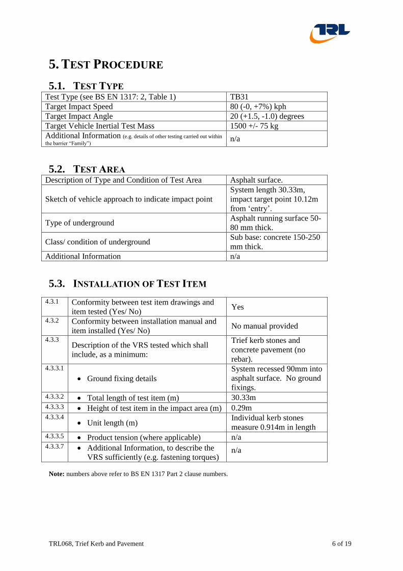
5. TEST PROCEDURE
5.1. TEST TYPE Test Type (see BS EN 1317: 2, Table 1) TB31
Target Impact Speed 80 (-0, +7%) kph
Target Impact Angle 20 (+1.5, -1.0) degrees
Target Vehicle Inertial Test Mass 1500 +/- 75 kg
Additional Information (e.g. details of other testing carried out within
the barrier “Family”) n/a
5.2. TEST AREA Description of Type and Condition of Test Area Asphalt surface.
Sketch of vehicle approach to indicate impact point
System length 30.33m,
impact target point 10.12m
from ‘entry’.
Type of underground Asphalt running surface 50-
80 mm thick.
Class/ condition of underground Sub base: concrete 150-250
mm thick.
Additional Information n/a
5.3. INSTALLATION OF TEST ITEM
4.3.1 Conformity between test item drawings and
item tested (Yes/ No) Yes
4.3.2 Conformity between installation manual and
item installed (Yes/ No) No manual provided
4.3.3 Description of the VRS tested which shall
include, as a minimum:
Trief kerb stones and
concrete pavement (no
rebar). 4.3.3.1
Ground fixing details
System recessed 90mm into
asphalt surface. No ground
fixings. 4.3.3.2 Total length of test item (m) 30.33m 4.3.3.3 Height of test item in the impact area (m) 0.29m 4.3.3.4
Unit length (m) Individual kerb stones
measure 0.914m in length 4.3.3.5 Product tension (where applicable) n/a 4.3.3.7 Additional Information, to describe the
VRS sufficiently (e.g. fastening torques) n/a
Note: numbers above refer to BS EN 1317 Part 2 clause numbers.
Page 7
TRL068, Trief Kerb and Pavement 7 of 19
5.4. VEHICLE
Make Rover
Model 75
Body Style Saloon
Year 2004
VIN SARRJHLPB4D326680
Vehicle roadworthiness assessment (inc.
date of assessment, e.g. MOT)
MOT Certificate present (ref: 377339902142),
expires 17/04/2013.
Condition Good.
Vehicle Mass 1500kg Compliance Yes
Ballast Mass 166kg Compliance Yes
Description of ballast 24kg remote brake system, 11kg DAU and
battery in boot, 5kg of guidance hub, 1.5kg
radio equipment on boot lid, 15.5kg rope
release mechanism on tunnel and 1kg rope
release battery. Ballast weights fitted in rear
foot wells and roof (108kg total).
Dummy Mass, Type & Position (if fitted) None
Total Test Mass 1,500kg Compliance Yes
Track Width Front 1511mm Compliance Yes
Rear 1489mm Compliance Yes
Centre of Mass Aft of front axle 1210mm Compliance Yes
Lateral from centre line 0mm to right Compliance Yes
Above ground 533mm Compliance Yes
Drive (LHD/ RHD) RHD
Drive (FWD/ RWD) FWD
Number of axles Two
Transmission (Manual/Automatic) Manual
Tyre Size 195/65 R15
Wheel radius mm 295mm
Tyre Pressure Front 30 psi
Rear 30 psi
Ride Height
Front LHS 693mm
RHS 681mm
Rear LHS 680mm
RHS 669mm
Wheelbase LHS 2753mm
RHS 2751mm
Maximum Width (excluding side mirrors) 1748mm
Front Overhang 911mm
Overall Vehicle Length 4727mm
Any additional information
The following parts were removed: Handbrake, jack and tools, boot liner, handbrake and
centre console (to accommodate rope release mechanism and instrumentation).
Page 8
TRL068, Trief Kerb and Pavement 8 of 19
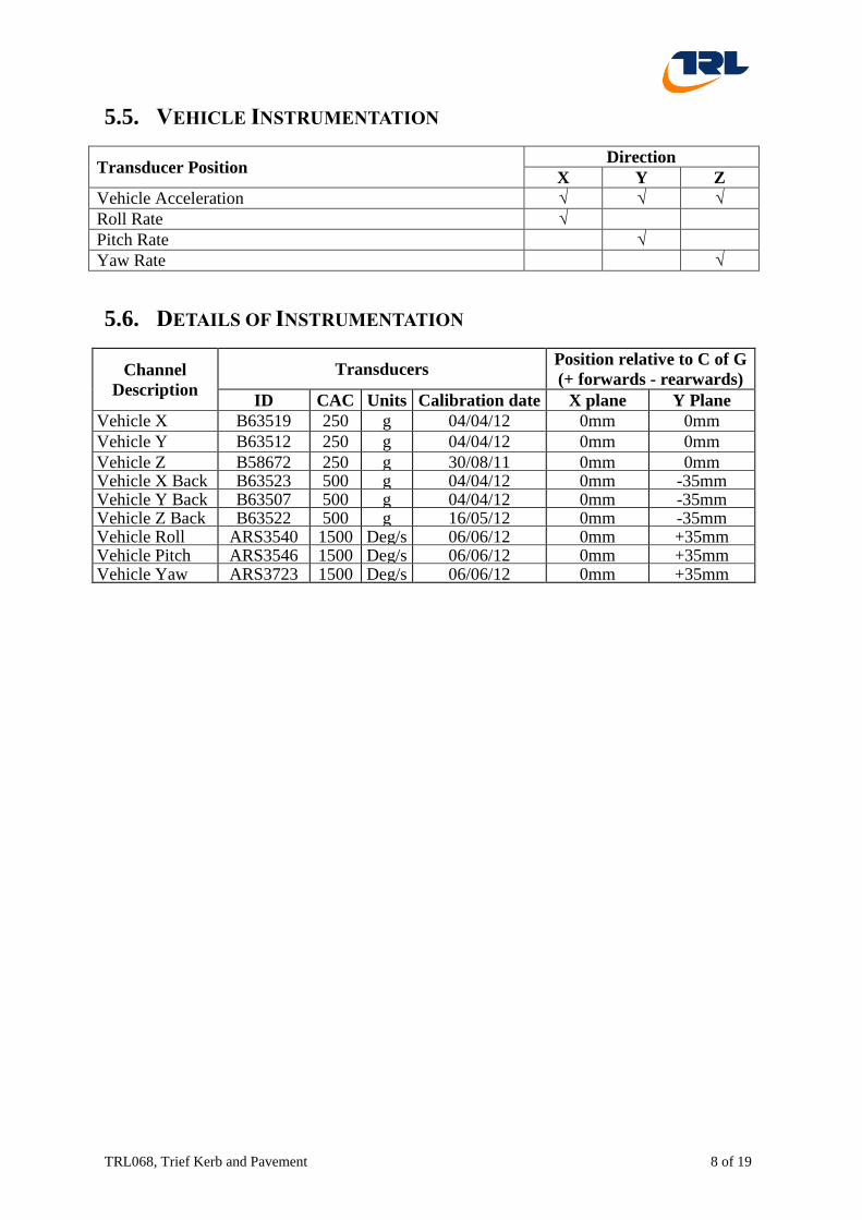
5.5. VEHICLE INSTRUMENTATION
Transducer Position Direction
X Y Z
Vehicle Acceleration √ √ √
Roll Rate √
Pitch Rate √
Yaw Rate √
5.6. DETAILS OF INSTRUMENTATION
Channel
Description
Transducers Position relative to C of G
(+ forwards - rearwards)
ID CAC Units Calibration date X plane Y Plane
Vehicle X B63519 250 g 04/04/12 0mm 0mm
Vehicle Y B63512 250 g 04/04/12 0mm 0mm
Vehicle Z B58672 250 g 30/08/11 0mm 0mm Vehicle X Back
up
B63523 500 g 04/04/12 0mm -35mm Vehicle Y Back
up
B63507 500 g 04/04/12 0mm -35mm Vehicle Z Back
up
B63522 500 g 16/05/12 0mm -35mm Vehicle Roll
Rate
ARS3540 1500 Deg/s 06/06/12 0mm +35mm Vehicle Pitch
Rate
ARS3546 1500 Deg/s 06/06/12 0mm +35mm Vehicle Yaw
Rate
ARS3723 1500 Deg/s 06/06/12 0mm +35mm
Page 9
TRL068, Trief Kerb and Pavement 9 of 19
6. RESULTS
Test Number TRL068
Date 17 July 2012
Weather Conditions Sunny/ overcast
Track Surface Dry, swept.
Temperature (nominal) 20.3deg C
Additional information n/a
6.1. IMPACT CONDITIONS AND INTERACTION WITH BARRIER
Impact speed 80.3km/h
Difference from target speed + 0.4%
Impact speed within tolerance Yes
Impact angle 19.9degrees
Difference from target angle -0.1 degrees
Within tolerance envelope (BS EN 1317–2 Figure 3) Yes
Vehicle breaches barrier No
During and after the impact, no more than one wheel of the vehicle
passes over the rearmost part of the deformed system (yes/ no/ n-a) n/a
Vehicle within ‘exit box’ Yes
Vehicle rolls over within test area No
Major part of vehicle detached No
For VRS to be mounted on bridges, retaining walls or on other
structures: vehicle or tested item supported by any structure beyond the
bridge deck edge (yes/ no/ n-a)
n/a
Graphs of the vehicle instrumentation output may be found in Section 11
6.2. TEST SEQUENCE The vehicle was towed and guided to the impact area by means of wire ropes, one of which
was attached to a continuous loop of steel cable, driven by a computer controlled hydraulic
propulsion system. Immediately before impact, the towing cable and guidance cables were
detached and the vehicle travelled freely, at the specified speed, into the barrier.
The speed of the vehicle immediately before impact was measured by a photoelectric device
positioned a short distance (approximately 5m) from the impact point. Photographic
coverage of the test was carried out using the required array of high speed cameras specified
in BS EN 1317-2.
The front right hand side (RHS) corner of the vehicle contacted the barrier, at the intended
impact point and immediately began to deform, leaving the first (bodywork) witness marks
9.830m from the entry end of the system. The RHS front wheel was damaged on impact. As
the deformation of the front RHS continued, the vehicle yawed, concurrently pitching and
rolling. During this movement, all four wheels lifted from the running surface. As the
Page 10
TRL068, Trief Kerb and Pavement 10 of 19
vehicle came back into contact with the running surface, the RHS front wheel was displaced
further (it should be noted that the damaged wheel remained attached throughout the impact).
The vehicle continued on its redirected path away from the kerbing, with minimal pitching
and rolling. The vehicle’s wheel track did not cross the exit box line, and it continued past
the departure end of the system, remaining within the exit box boundary line (see below for
additional details). The vehicle was remotely braked and came to rest, with no further impact
damage sustained.
Note: During the vehicle acceleration and approach, the vehicle experienced a left front
wheel lockup (non impact side); this did not affect the parameters of the test, and was later
determined to be a seized brake calliper.
6.3. TEST ITEM PERFORMANCE Maximum Dynamic Deflection (m) 0.0m
Normalised Dynamic Deflection (m) 0m
Working Width (m) 1.38m (the width of the system)
Normalised Working Width (m) 1.38m (the width of the system)
Class of Working Width W5
Maximum Permanent Deflection of Barrier (m) 0m
Length of Contact (m) 5.14m
Impact Point (start of paint witness marks) (m) 9.83m from entry
Major parts fractured or detached No
Describe movement of end anchors n/a
Ground Fixing meets design levels n/a
6.4. VISUAL MEDIA RECORDS Digital stills were taken of the barrier and the vehicle pre and post-test. Particular stills are
referred to in the text. Video evidence of the test was also taken.
6.4.1. PRE TEST PHOTOGRAPHS Description Photograph
Vehicle front TRL068_S015
Vehicle rear TRL068_S018
Vehicle left hand side TRL068_S019
Vehicle right hand side TRL068_S017
Vehicle at impact point (front view) TRL068_S028
DAU and remote brake unit TRL068_S027
Instrumentation TRL068_S022
Page 11
TRL068, Trief Kerb and Pavement 11 of 19
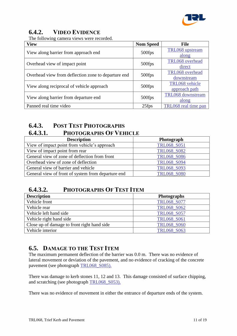
6.4.2. VIDEO EVIDENCE The following camera views were recorded.
View Nom Speed File
View along barrier from approach end 500fps TRL068 upstream
along
Overhead view of impact point 500fps TRL068 overhead
direct
Overhead view from deflection zone to departure end 500fps TRL068 overhead
downstream
View along reciprocal of vehicle approach 500fps TRL068 vehicle
approach path
View along barrier from departure end 500fps TRL068 downstream
along
Panned real time video 25fps TRL068 real time pan
6.4.3. POST TEST PHOTOGRAPHS
6.4.3.1. PHOTOGRAPHS OF VEHICLE Description Photograph
View of impact point from vehicle’s approach TRL068_S051
View of impact point from rear TRL068_S082
General view of zone of deflection from front TRL068_S086
Overhead view of zone of deflection TRL068_S094
General view of barrier and vehicle TRL068_S093
General view of front of system from departure end TRL068_S080
6.4.3.2. PHOTOGRAPHS OF TEST ITEM Description Photographs
Vehicle front TRL068_S077
Vehicle rear TRL068_S062
Vehicle left hand side TRL068_S057
Vehicle right hand side TRL068_S061
Close up of damage to front right hand side TRL068_S060
Vehicle interior TRL068_S063
6.5. DAMAGE TO THE TEST ITEM The maximum permanent deflection of the barrier was 0.0 m. There was no evidence of
lateral movement or deviation of the pavement, and no evidence of cracking of the concrete
pavement (see photograph TRL068_S085).
There was damage to kerb stones 11, 12 and 13. This damage consisted of surface chipping,
and scratching (see photograph TRL068_S053).
There was no evidence of movement in either the entrance of departure ends of the system.
Page 12
TRL068, Trief Kerb and Pavement 12 of 19
6.6. DAMAGE TO THE VEHICLE The following damage to the vehicle was recorded:
The RHS of the front bumper was displaced (cracked around fixing points);
The RHS front wing was dented and creased;
The RHS front wheel was damaged and displaced, with significant damage to the
steering arm;
The RHS sill between front and rear wheel, shows scratching and surface damage;
The RHS front tyre was deflated;
The LHS front tyre was deflated;
Engine coolant reservoir was displaced on impact.
There was no significant damage or intrusion to the passenger compartment.
6.7. EXIT BOX The exit box line was marked at 4.704m from the traffic face of the system (for calculations
of exit box criteria reference BS EN1317-2: 2010 paragraph 4.3).
To aid post-test analysis a line of sand was applied to the exit box line, so that (should the
vehicle cross the line) the displacement of the sand could be used to confirm whether or not
exit box criteria ‘B’ was met (reference EN1317-2: 2010 Table 7).
The vehicle did not cross the exit box line at any point, therefore the criteria was met.
6.8. VEHICLE COMPARTMENT DEFORMATION INDEX (VCDI)
Position Pre-Test
(mm)
Post-Test
(mm)
Difference
Pre-test – Post-test
mm %
Distance between the dashboard and top of
the rear seat 1843 1843 0 0
Distance between the roof and the floor
panel 1314 1313 -1 0
Distance between the rear seat and the
motor panel 2217 2217 0 0
Distance between the lower dashboard and
the floor panel 469 467 -2 -0.5
Interior width 1447 1447 0 0
Distance between the lower edge of the
right window and the upper edge of the left
window
1293 1292 -1 0
Distance between the lower edge of the left
window and the upper edge of the right
window
1294 1294 0 0
Vehicle cockpit deformation index VCDI AS0000000
Page 13
TRL068, Trief Kerb and Pavement 13 of 19
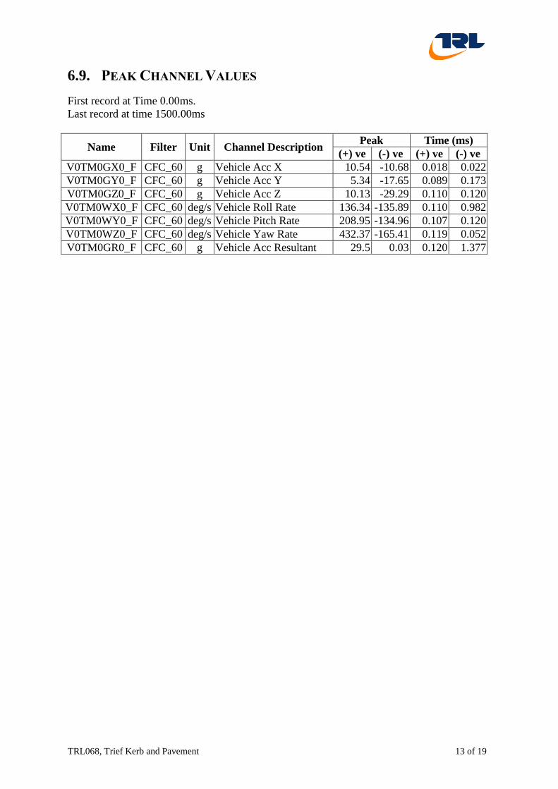
6.9. PEAK CHANNEL VALUES
First record at Time 0.00ms.
Last record at time 1500.00ms
Name Filter Unit Channel Description Peak Time (ms)
(+) ve (-) ve (+) ve (-) ve
V0TM0GX0_F CFC_60 g Vehicle Acc X 10.54 -10.68 0.018 0.022
V0TM0GY0_F CFC_60 g Vehicle Acc Y 5.34 -17.65 0.089 0.173
V0TM0GZ0_F CFC_60 g Vehicle Acc Z 10.13 -29.29 0.110 0.120
V0TM0WX0_F CFC_60 deg/s Vehicle Roll Rate 136.34 -135.89 0.110 0.982
V0TM0WY0_F CFC_60 deg/s Vehicle Pitch Rate 208.95 -134.96 0.107 0.120
V0TM0WZ0_F CFC_60 deg/s Vehicle Yaw Rate 432.37 -165.41 0.119 0.052
V0TM0GR0_F CFC_60 g Vehicle Acc Resultant 29.5 0.03 0.120 1.377
Page 14
TRL068, Trief Kerb and Pavement 14 of 19
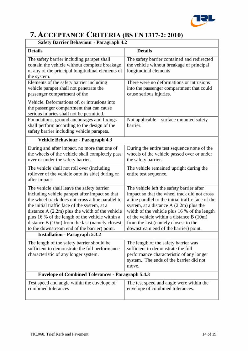
7. ACCEPTANCE CRITERIA (BS EN 1317-2: 2010)
Safety Barrier Behaviour - Paragraph 4.2
Details Details
The safety barrier including parapet shall
contain the vehicle without complete breakage
of any of the principal longitudinal elements of
the system.
The safety barrier contained and redirected
the vehicle without breakage of principal
longitudinal elements
Elements of the safety barrier including
vehicle parapet shall not penetrate the
passenger compartment of the
Vehicle. Deformations of, or intrusions into
the passenger compartment that can cause
serious injuries shall not be permitted.
There were no deformations or intrusions
into the passenger compartment that could
cause serious injuries.
Foundations, ground anchorages and fixings
shall perform according to the design of the
safety barrier including vehicle parapets.
Not applicable – surface mounted safety
barrier.
Vehicle Behaviour - Paragraph 4.3
During and after impact, no more that one of
the wheels of the vehicle shall completely pass
over or under the safety barrier.
During the entire test sequence none of the
wheels of the vehicle passed over or under
the safety barrier.
The vehicle shall not roll over (including
rollover of the vehicle onto its side) during or
after impact.
The vehicle remained upright during the
entire test sequence.
The vehicle shall leave the safety barrier
including vehicle parapet after impact so that
the wheel track does not cross a line parallel to
the initial traffic face of the system, at a
distance A (2.2m) plus the width of the vehicle
plus 16 % of the length of the vehicle within a
distance B (10m) from the last (namely closest
to the downstream end of the barrier) point.
The vehicle left the safety barrier after
impact so that the wheel track did not cross
a line parallel to the initial traffic face of the
system, at a distance A (2.2m) plus the
width of the vehicle plus 16 % of the length
of the vehicle within a distance B (10m)
from the last (namely closest to the
downstream end of the barrier) point.
Installation - Paragraph 5.3.2
The length of the safety barrier should be
sufficient to demonstrate the full performance
characteristic of any longer system.
The length of the safety barrier was
sufficient to demonstrate the full
performance characteristic of any longer
system. The ends of the barrier did not
move.
Envelope of Combined Tolerances - Paragraph 5.4.3
Test speed and angle within the envelope of
combined tolerances
The test speed and angle were within the
envelope of combined tolerances.
Page 15
TRL068, Trief Kerb and Pavement 15 of 19
7.1. ASSESSMENT OF IMPACT SEVERITY
Using vehicle accelerometer corrected to CofG
Limit CFC_180 13Hz filter
Acceleration Severity Index ASI (rounded to 1 d.p.) 1.9 1.0 0.9
Theoretical Head Impact Velocity THIV (km/h) 33 23 23
Post Impact Head Deceleration PHD (g) 20 9 5
Flail Space 0.6 x 0.3m 0.6 x 0.3m 0.6 x 0.3m
Time of Flight (ms) 241.2 247.5
Occupant Impact Velocity
OIV (m/s)
Forward Limits not
specified in
BS EN
1317
319 3.2
Lateral 5.4 5.3
Occupant Ridedown
Acceleration ORA (g)
Forward -3.8 -2.1
Lateral -9.3 -4.6
Injury severity parameters are calculated using TRL autosequence thiv_phdq.aut (date
10/02/2010) running in DIADEM version 9.10.2036 TDM.
8. CONCLUSION
The overall length of the system, measured from the extreme ends was 30.33m.
The total test mass of the vehicle was 1,500kg, the impact speed was 80.3km/h and the
impact angle was 19.9degrees, therefore the impact conditions were compliant with the
Standard and satisfactory.
The dynamic deflection was 0.0m and the working width was 1.38m (the width of the
system) (Class W5). The permanent deflection of the system was 0.0m.
The system fully complied with the acceptance criteria for this TB31 test with an ‘A’ rating
for impact severity level.
9. GENERAL STATEMENTS
The test results in this report relate only to the items tested.
This report may not be reproduced other than in full, except with the prior written approval of
the issuing laboratory.
The vehicle and test preparation were carried out by test engineers from TRL, under the
supervision of the TRL test manager.
Page 16
TRL068,Trief Kerb and Pavement 16 of 19
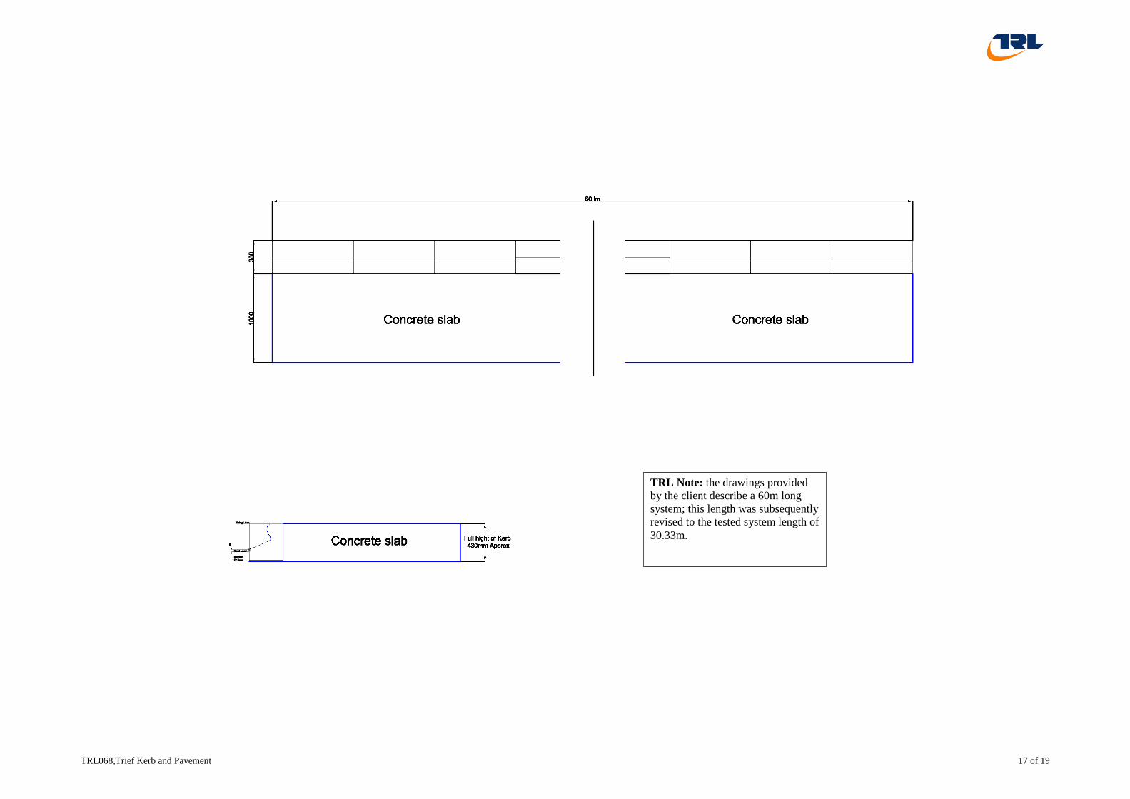
10. ANNEX A - DRAWINGS AND INSTALLATION OF THE TEST ITEM
Page 17
TRL068,Trief Kerb and Pavement 17 of 19
TRL Note: the drawings provided
by the client describe a 60m long
system; this length was subsequently
revised to the tested system length of
30.33m.
Page 18
TRL068, Trief Kerb and Pavement 18 of 19
11. ANNEX B - ACCELERATION & RATE GRAPHS 11.1. B1 - VEHICLE ACCELERATION
Max Value 10.5g Min Value -10.7g
TRL068
Filtered at CFC_60
Max Value 5.3g Min Value -17.7g
Filtered at CFC_60
Positive to right
Max Value 10.1g Min Value -29.3g
Filtered at CFC_60
Positive forwards
Positive downwards
Max Value 29.5g
Filtered at CFC_60
0 100 200 300 400 500 600 700 800 900 1000 1100 1200 1300 1400 1500
Time - ms
-30
-25
-20
-15
-10
-5
0
5
10
15
Ve
hic
le A
cc X
- g
0 100 200 300 400 500 600 700 800 900 1000 1100 1200 1300 1400 1500
Time - ms
-30
-25
-20
-15
-10
-5
0
5
10
15
Ve
hic
le A
cc Y
- g
0 100 200 300 400 500 600 700 800 900 1000 1100 1200 1300 1400 1500
Time - ms
-30
-25
-20
-15
-10
-5
0
5
10
15
Ve
hic
le A
cc Z
- g
0 100 200 300 400 500 600 700 800 900 1000 1100 1200 1300 1400 1500
Time - ms
0
5
10
15
20
25
30
Ve
hic
le A
cc R
esu
lta
nt
- g
Evalu
ation V
ers
ion
Page 19
TRL068, Trief Kerb and Pavement 19 of 19
11.2. B2 - ANGULAR RATE OF THE VEHICLE
Max Value 136.3deg/s Min Value -135.9deg/s
Filtered at CFC_60
Max Value 209.0deg/s Min Value -135.0deg/s
Filtered at CFC_60
Positive clockwise from rear
Positive clockwise from left
Roll Rate
Pitch Rate
Max Value 432.4deg/s Min Value -165.4deg/s
Filtered at CFC_60
Positive clockwise from above
Yaw Rate
TRL068
0 100 200 300 400 500 600 700 800 900 1000 1100 1200 1300 1400 1500
Time - ms
-200
-150
-100
-50
0
50
100
150
200
250
300
350
400
450
Ve
hic
le R
oll
Ra
te -
de
g/s
0 100 200 300 400 500 600 700 800 900 1000 1100 1200 1300 1400 1500
Time - ms
-200
-150
-100
-50
0
50
100
150
200
250
300
350
400
450
Ve
hic
le P
itch
Ra
te -
de
g/s
0 100 200 300 400 500 600 700 800 900 1000 1100 1200 1300 1400 1500Time - ms
-200
-150
-100
-50
0
50
100
150
200
250
300
350
400
450
Ve
hic
le Y
aw
Ra
te -
de
g/s
Evalu
ation V
ers
ion