BS EN 295-L: 1991 Incorporattng Amend.ments Nos l, 2 and 3 Vitrified clay pipes and fittings and pipe joints for drains and sewers - Part 1: Requirements The European Standard EN' zgs-t'tggt with the inclusion of ameadments A1:1996, A2:1996 and A3:1999has the status of a Briiish Standard ICS 91.140.80 ;i.p Obtained from !trd reprcduced by Global Engineeritrg Documents with the *::E permission of BSI under .oyalty agreernenl -.-:--- lslnrerdess Way East, Englewood, Colorado 80112-576 USA 301792-2181 8N4U-3n4 NO COPYING WITHOUT BSI PERMISSON EXCEPT AS PERMITTED BY COPYRIGHT LAW rlt\- I-f G- r! I'I--I uv-
Transcript
BS EN 295-L:1991IncorporattngAmend.ments Nos l, 2and 3
Vitrified clay pipes andfittings and pipe jointsfor drains and sewers -
Part 1: Requirements
The European Standard EN' zgs-t'tggt with the inclusion of ameadmentsA1:1996, A2:1996 and A3:1999 has the status of a Briiish Standard
ICS 91.140.80
;i.p Obtained from !trd reprcduced by Global Engineeritrg Documents with the*::E permission of BSI under .oyalty agreernenl-.-:---
lslnrerdess Way East, Englewood, Colorado 80112-576 USA 301792-2181 8N4U-3n4
NO COPYING WITHOUT BSI PERMISSON EXCEPT AS PERMITTED BY COPYRIGHT LAW
r l t \-I-f G- r!I ' I - - Iuv-
BS EN 295-l:1991
Cooperating organizations
The European Committee for Standardization, under whose supervision thisEuropean Standard was prepared, comprises the national standardsorganizations of the following Western European muntries.
Oesterreichisches NormungsinstitutInstitut belge de normalisationDansk StandardiseringsraadSuomen Standardisoimisliito, r.y.Association frangaise de normalisationDeutsches Institut fiir Norroung e.V.
Hellenic Organization for StandardizationTechnological Institute of IcelandNational Standards AuthoritY of IrelandEnte Nazionale Itaiiano di UnificazioneInspection du Travail et des !tinesNederlands Normalisatie-instituutNorges StandardiseringsforbundInstituto Portuguds da QualidadeAsociaci5n Espaiola de Normalizaci6n y Certificaci6n'Standardiseringskommissionen i Sverige
Association suisse de normaiisaiionBritish Standards Institution
This British Standard waspublished under the authoritt'of the StandaldsBoard and cornesinto effect on31 October 1991
o BsI t2-1999
The following BSI referencesrclate to the work on thisstandard:Committee reference 8/505Drafi for comnent E9/15819
Arrlendrnents issued since rrublication
{ t t
ifi
Contents
Cooperating organizationsNational foreword
PageInside front cover
ii
EN forewordText of EN 295-1:1991National appen{ix.rN$ (inform atlve) Inside back cover
@ BSI 12-1999
BS EN 295-1:1991
National foreword
This British Standard has been prepared by Technical Committee 8/505, Wastewater engineering. It is the English language version of EN 295'1:1991 includingamendments A1:1996. A2:1996 and A3:1999.
Cross-referencesThe British Standards which implement international or European publicationsreferred to in this document may be found in the BSI Standards Catalogue underthe section entitled "International Standards Correspondence Index", or by usingthe "Find" facility of the BSI Standards Electronic Catalogue.
A British Standard does not purport to include all the necessary provisions of acontract. Users of British Standards are responsible for their correct application.
Colnpliance with a British Standard does not of itself confer immunityfrom legal obligations.
Sumrnary of pages
This document comprises a front cover, an inside front cover, pages i and ii,the EN title page, pages 2 to 5 and a baek cover.The BSI copyright notice displayed in this document indicates when thednerrrncnf rwas I ect issrrcd
Vitrified clay pipes and fittings and pipe joints fordrains and sewers -Part 1: Requirements
(includes amendments A1:1996, A2:1996 and A3:1999)
Tuyaux et accessoires en grds et assemblages de Steinzeugrohre und Formstiicke sowletuyaux pour les rrlseaux de branchement et Rohrverbindungen fiir Abwasserleitungend'assainissement - und -kaniile -
Partie 1: Exigences TeiI 1: Adorderungen(inclut les amendements A1:1996, A2:1996 et (enthdlt Anderungen A1:1996, 42:1996 undA3:1999) 43:1999)
This European Standard was approved by CEN on 1996" 10- f6, amendment Alwas approved by CEN on 1996-02-23, amendment .{2 was approved by CENon 1996-09-14, amendment A3 was approved by CEN on 1991-01'28. CENmembers are bound to comply with the CEN/CENELEC Internal Regulationswhich stipulate the conditions for giving this European Standard the status ofa national standard without any alteration.Up-to-date lists and bibliographical references concerning such nationalstandards may be obtained on application to the Central Secretariat or to anyCEN member.This European Standard exists in three official versions (English, French,
' German). A version in any other language made by translation under theresponsibiiity of a CEN member into its own language and notilied to theCentral Secretariat has the same status as the official versions.
CEN members are the national standards bodies of Austria, Belgium,Denmark, Finland, France, Germany, Greece, Iceland, Ireland, Italy,Luxembourg, Netherlands, Norway, Portugal, Spain, Sweden, Switzerland andUnited Kingdom.
CEN
"'diiliu""",r#1|ii".?',f":ilff :*ffi'"Europiiisches Komitee fiir Normung
,_.,- Central Secretariatr rue de Stassart 36, 8-1050 Brussels
Oilbg1 All rights of reproduction and communication in any form and by any means reserved in allcoiiiitries to CEN and its membr)rs
Ref. No. EN 29b-1:199r + A1:1996 + 42:1996 + A3:1999 E
. /
EN 295-1:1991
Foreword
This part ofthe European Standard for vitrilied claypipes is the frrst ofthree parts which was drafted byWG2 "Vitrified clay pipes" of the technicalCommittee CEN/TC 165'Waste water engineering"secretariat of which is held by DIN.
Vitrified clay pipes and fittings and pipe joints fordrains and sewers Part 2: Quality control andsampling" contains the complete quality control.Vitrified clay pipes and fittings and pipe joints forlrains and sewers Part 3: Test methods" contains;he necessary statements on the testing methods.Other parls may be added later
Cn drafting this standard the provisional resultsrlready available of CEN/TC 165/!VCl "Generalrequirements on pipes, fittings, pipe joints including;ealings and manholes" or other relevant workinggroup ofTC 165 with general responsibilities were:aken into account- When further results areieceived, any necessary amendments will be made.
in accordance with the Common CEN/CENELECRules, the following countries are bound to:mplement this European Standard:-
lustria, Belgium, Denmark, Finland, France,3ermany, Greece, Iceland, Ireland, Italy,-uxembourg, Netherlands, Norway, Poftugal,ipain, Sweden, Switzerland and United Kingdom.y'itrified clay pipes in permanent or in temporaryrontact with water intended for human:onsumption will not affect the quality of that.vater. Therefore this standard does not contravene;he EC-Council Directives 75144O, 791869, 80177a.Ihis standard taki:s into account the essential'equirements of the EC-Council Directive for:onstruction products (89/1O6) and the Draftlirective on the treetment ofrnunicipal waste+ater ICOM (89) 5r8].
Foreword of amendment Al
lhis amendment EN 295- i:1991/A1:1996 to the1N 295-1:1991 has been prepared by Technicallommittee CEN/TC 165, Waste water engineering,.he secretariat of which is held by DIN.fhe draft European Standard contains changes andrdditions to Table 11 and Table 11 oflN 295.1:1991.
CEN rrembers will decide whether the complete orcorrected Table 11 and Table 11 will be publishedseparately from the original version ofEN 295-1:1991 as an amendment or the changeswill be incorporated in a revised publication of thestandard. It will be up to the CEN members todecide which option to take. These options areallowed under clause M.3 of the CEN InternalRegulations Part 3.This amendment to the European StandardEN 295-1:1991 shall be given the status of anational standard, either by publication of anidentical text or by endorsement, at the latest byOctober 1996, and conllicting national standardsshall be withdrawn at the latest by October 1996.
According to the CEN/CENELEC InternalRegulations, the national standards organizationsof the following countries are bound to implementthis amendment: Austria, Belgium, Denmark,Finland, France, Germany, Greece, Iceland,Ireland, Italy, Luxembourg, Netherlands, Norway,Portugal, Spain, Sweden, Switzerland and theUnited Kingdom
Foreword of amendment A2
This amendmeni EN 295-1:1991/A2:1996 to theEN 295-1:1991 has been prepared by TechnicalCommittee CEN/IC 165, Waste water engineering,the secretariat of which is held by DIN.
Amendment A1 contain changes and additions toTable 11 and Table 11 of EN 295-1:1991. Thisamendnent contains a change to Table 9 for thetensile strength ofpolypropylene for sleevecouplings. There will be-an amendment to 16.2 ofEN 295-3:1991 for the rate of grip separation to beSpeed C (50 mm/min + 10 %).CEN members will decide whether the complete orcorrected Table 11 and Table 11 wiil be publishedseparately from the original version ofEN 295-1:1991 as an amendment or the changeswill be incorporated in a revised publication of thestandard. It will be up to the CEN members todecide which option to take. These options areallowed under M.3 of the CEN/CENELEC InternalRegulations Part 3.This amendment to the European StandardEN 295-1:1991 shall be given the status of anational standard, either by publication of anidentical text or by endorsement, at the latest byApril 1997, and conllicting national standards shallbe withdrawn at the latest by April 1997.
;..!i
According to the CEN/CENELEC InternalRegu.lations, the national standards organizationsof thb following countries are bound to inplementthis European Standard: Austria, Belgium,Denmark, Finland, France, Germany, Greece,Iceland, Ireland, Italy, Luxembourg, Netherlands,Norway, Portugal, Spain, Sweden, Switzerland andthe United Kingdom.
Foreword to amendment AB
This amendment EN 295-1:1991/A3:1999 toEN 295-1:1991 has been prepared by TechnicalCommittee CEN/IC 165, Waste water engineering,the Secretariat of which is held by DIN.
This amendment to the European StandardEN 295-1:1991 shall be given the status ofanational standard, either by publication of anidentical text or by endorsement, at the Iatest bySeptember 1999, and con{licting national standardsshall be withdrawn at the latest by September 1999.
For adaptation of DN 295-1:1991 to new publishedEuropean Standards aroendments were necessary.
Ell295-1:1991 in the French version containseditorial mistakes concerning the use of auxiliaryverbs. For adaptation of the French versiorrto theEnglish and German versions this amendment alsocontains a list of additional editorial amendmentsconcerning only the French version and thereforeare not put at disposal in English and Germanlanguages.The CEN-members wiil decide whether the changeswill be published separately from the originaiversion of EN 295-1:1991 or the changes will beincorporated in a revised publication of thestandard. These options are allowed underclause M.3 of the CEN/CENELEC internalregulations Part 3.
According to the CEN/CENELEC InternalRegulations, the national standards organizationsof the following countries are bound to implementthis European Standard: Austria, Belgium, CzechRepublic, Denmark, Finland, France, Germany,Greece, Iceland, Ireland, Italy, Luxembourg,Netherlands, Norway. Portugal, Spain, Sweden,Switzerland and the United Kinsdom.
Cogtents
: '.-uN loreworoi. ' ueneral
1.1 Object and field ofapplication1.21:" References1-3.t Delinitions
1.3ff Nominal size
EN 295-1:1991
CurvatureJoint assembly
Bearing elements
Sealing elements
FairingsMinimum bore
Pipe sectionNominal length
Pipes and fittings
Materials and manufacture
Minimum bore
L€ngthSquareness of ends
Deviation from straightness
Water seal of httings
Angle of curvature and radius of bends
Branch angle of junctions
Crushing strength (Fl0
Bending tensile strength
Bending moment resistance (BMR)
Bond strength of adhesive used forfrxing fued clay pans together
3.7 Chemicai and physical resistanceto effluent 13
3.?.1 Joint assemblies 13
3.7.2 Jointing materials 13
3.8 Thermal cYcling stabilitY 14
3.9 Long-term thermal stability 14
4 SamPling for tests 14
5 Designation 14
6 Marking 14
? Quality Assurance 14
Figure 1- Joint dimensions 13
Table I - Minimum bore 6
Table 2 - Preferred nominal lengths 6
Table 3 - Deviation from straightness 6
Table 4 - Crushing strength (FN) in kN/m
DN 100 and 150 t
Table 5 - Crushing strength (FN)
in kN/m = DN 200 t
Table 6 - Bending moment resistance (BM
in kN.m for crushing strength values (FN)
in kN/m t
Table ? - Material requirements forpolyurethane sealing elements 9
Table 8 - Material requirements foqpolypropyiene sleeve couplings 10
Table 9 - Deflection 10
Table 10 - Dimensions and tolerances for
socket controlled jointing systems 12
Table 11 - Dimensions and tolerances for
sfigot controlled jointing systems 12
EN 295-1:1991
t General 1,3.2curvature
1.1 Obj ect and field of application the angle subtended by the Iength of a curve.d fitting
This part of this Eumpean stanclarcl specifies at the centre of a circle of nominal radius through
t"q"i'r".""t" fot nu*iily loint"d t'ittified clay pipes the centreline of the fitting
anil. frttings with or without sockets for thg. i ,,.,, . . ,. .1.3.3construction of drainage and sewerage systems. joint assemblyAlthough normally operated under gravity' thepifiJ and fittings covered by this standard willaciept periodic hydraulic surcharge.
Ifpipes are required to withstand continuouswoiking under low pressure, the pressure used intests in this standard shall be agreed between thema-nufacturer and the purchaser with a maximuntest pressure of 600 kPa (6,0 bar).
The preferred dimensions for pipe lengths,curvature of bends and angles ofjunction arms alespecifred in this standard. Other values for thesedimensions are acceptable providing the productsmeet all the relevant performance requirementsand are marked correctly.
Fittings groups covered by this part of this standardare given in Table 2 of EN 295-2
Where this standard provides for different strengthclasses, different syslems of jointing dimensions,different lengths and different Frttings, thespecifiers/purchasers may select according to theirrequirements.
1.2 ReferencesEN 295-2:1991, Vitrified clay pipes and fittings andpipe joints for dratns and sewers : Port 2: Qudlitfcontrol and sampling.
EN 295-3:1991, Vitrified clay pipes and fittings andpipe joints for drains and. sewers : Part 3: Testmelhods.
EN 681-1:1996, Elastomeric seals - Iliaiirial',':: '
requtrements lor pipe joint seals used in water andd.rainoge applications - Part l: Vulcanized rubber-
1.3 DefinitionsFor the purposes of this European Standard thefolloqing deiinitions. apply:
1.3:1:noffinal size (DN)
a riiiiierical designation of size which is acofflnient round numberequal to or approximatelyeq[i] to the bore in millimetres
the adjacent ends of pipes, fittings or adaptors andthe means ofjoining them
r..3.4bearing elements
spigots and sockets or couplings designed to includesealing elements with or without fairings
1.3.5sealing elements
factory made components which seal the joints, andare supplied by the pipe manufacturer
1.3.6fairings
any components located between bearing andsealing elements to reduce tolerances of sealingsurfaces
1.3.7minirnum bore
smallest bore measured within 100 mm of the endsof the pipe
r.3.8pipe section
a short length of pipe barrel equal to or greaterthan 300 mm
1.3.9nominal length
numerical designation of length approximatelyequal to the internal length of the pipe bairel
2 Pipes and fittings
2.1 Materials and manufacture
.Pipes and fittings shall be made from suitable clays'':and frred to'vitrification. The clays shall be of such
a quality and homogeneity that the final product isin accordance with this standard. Pipes and fittings
. shall be.sound and free from such defects as wouldimpair their function when rn servrce.
Visual imperfections, such as missing glaze,unevenness, creasings in the transition from pipe tosocket and slight surface damage are acceptable,providing the impermeability, durability and flowcharacteristics of the pipes and fittings areunaffected.
o Bsl 12.1999
EN 295-1:1991
Pipes and fittings may be unglazed or glazed on theinierior and/or exterior. When glazed they need notbe glazed on the jointing surfaces ofthe spigot andsocket.Pipes and fittings are regarded as rigid (stif0' thejoints as flexible, and all have a high corrosionreslstance.
Fittings may be completed by fxing fued partstogether.Products may be surface treated after firing.
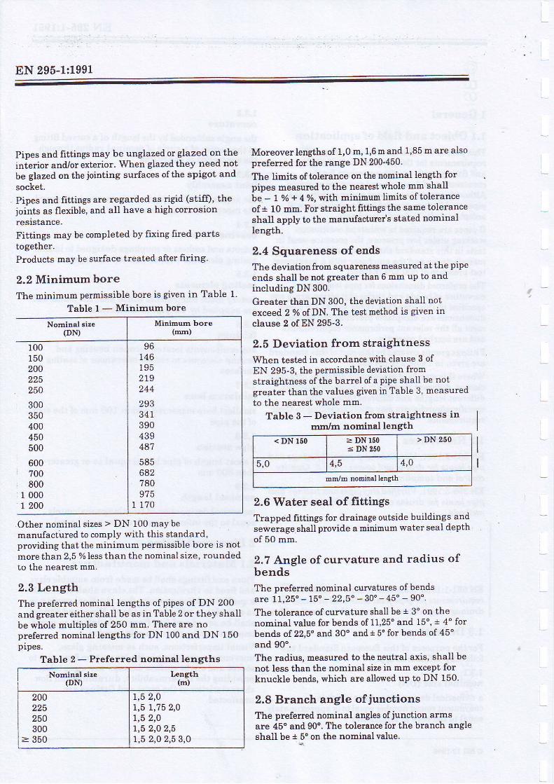
2.2 Minimum bore
The minimum permissible bore is given in Table 1.
Table l -Min imumbore
Nominal size(DN)
100i50200225250300350400450500
600700800
r 0001 200
.Other nominal sizes > DN 100 may bemanufactured to comply with this standard,providing that the minimum permissible bore is notmore than 2,5 % less than the nominal size, roundedto the nearest mm.
2.3 LengthThe preferred nominal lengths of pipes of DN 200and greater either shall be as in Table 2 or they shallbe whole multiples of 250 mm. There are nopreferred nominal lengths for DN 100 and DN 150prpes.
Table 2 - Preferred norninal lengths
Moreover lengths of 1,0 m, 1,6 m and 1'85 m are alsopreferred for the range DN 200'450.
The limits of tolerance on the nominal iength forpipes measured to the nearest whole mm shallbe - 1 o/o * 4 o/o, with minimum limits of toleranceof+ 10 mm. For straight fittings the same toleranceshall apply to the manufacturer's stated nominallength.
2.4 Squareness of endsThe deviation from squareness m€asured at the pipeends shall be not greater than 6 mm up to andincluding DN 300.
Greater than DN 300, the deviation shall notexceed 2 % of DN. The test method is given inclause 2 of EN 295-3.
2.5 Deviation from straightness
When tested in accordance with clause 3 ofEN 295-3, the permissible deviation fromstraightness of the barrel of a pipe shall be notgreater than the values given in Table 3, measuredto the nearest whole mm.
Table 3 - Deviation from straightness inmm/rrr nominal length
2.6 Water seal of fittingsTrappdd frttings for drainage outside buildings andsewerage shall provide a minimum water seal depthof 50 mm.
2.7 Angle of curvature and radius ofbendsThe preferred nominal curvatures of bendsare 11,25 ' - 15" - 22,5" - 30" - 45 ' - 90" .
The tolerance of curvature shall be + 3' on thenominal value for bends of 11,25' and 15", $ 4' forbends of 22,5" and 30" and + 5" for bends of 45"and 90'.The radius, measured to the neutral axis, shall benot less than the nominal size in mm except forknuekle bends, which are allowed up to DN 150.
2.8 Branch angle ofjunctionslhe preferreil nominal angles of junction armsare 45' and 90o. The tolerance for the branch angleshall be + 5o on the nominal value.
i.9 Crushing strength (FN)Iiiien tested in accordance with clause 4 ofEN 295-3, the crushing strength (FN) of pipes orpiie sections shall be not less than the values givenin Table 4 and Table 5.
Table 4 - Crushing strength (FM in kN/mDN 100 and 150
Higher crushing strengths may be declared forDN 100 or DN 150 pipes, provided that the increaseis in steps of 6 kN/m.
Table 5 - Crushing strength (FN) in kN/m
The crushing strength of other nominal sizes otherthan Class L shall be calculated from-the foqp.ula
Class number ' DN ^ -.,Llrushlng strength = -=j-jfroo- (kN/m)
Higtrer crushing strengths may be d"gi4.fgi-.,. .prgviding that they conform to the requirements ofthii next higher class. Class numbers are restrictedto 95, 120, 160 and 200, thereafter in incrementsoryO.NdiE For the purpose of skuctuBl desigh the nominal wallthiilness end/or nominal out.ride diametar should be declared bytlie.manufacturcr.
2.10 Bending tensile strength
Where whole pipes or pipe sections are not availablea bending tenlile strength test in accordahce withclause 5 of BN Zgf'g may be carried out on brokenpipe pieces to determine the crushing strength of apipe-
The crushing strength ofthe pipe shall be calculatedfrom the mean bending tensile strength ofat least 10 test pieces.
2.11 Bending moment resistance(BMR)When tested in accordance with clause 6 ofEN 295-3 the bending moment resistance for pipeswith nominal sizes up to and including 225 and withnominal iengths greater than 1,1 m shall be not lessthan that given in Table 6.
Higher bending moment resistance values may berequired ifhigher values for crushing strength thanthose in Table 4 and Table 5 are declared.
2.12 Bond strength of adhesive usedfor fixing fired clay parts together
2.12.1 Minimum bending tensile strength
Fabricated test specimens shall not fracturethrough the adhesive nor at the adhesive clayinterface under a bending tensile stressof 5 N/mm2 after full curing when made and testedin accordance with clause 7 of EN 295-3.
2.12.2 Minimum strength after immersion
Test as in 2.12.1 but after immersion in testsolutions as specified in clause 2O of EN 295-3.
i:::i,*
Nominalslze(D|0
Crushing strength(FI.O
100150
(22)(22)
z828
3434
4040
NOTE Brackets atound the stlengths denote shengths wherethere are no dirnensions Biven in Table 12
DN > 200
NominalSize(DM
Class [umber
I,1 r20 160 200 240
200225250300350
400450500600700
8001 0001 200
4 860
606060
4348
O J
7690
(24)(28)(30)3642
48
60728496
32364048oo
64728096
40
506070
80
48546072
96
NOTE Brackets around the shengths deuote strengths wherethere are no dimensions given in Tables 11 and 12.'i
lower strength pipes.
in kN/rn
Nominalsize(DN)
FN 3MR FN BMR F'N BMR rN BMR
100 22 1,0 2a 40 2,0
150 22 2,8 28 3,4 34 4,0 40 4,6
200 5,2 6,2 40 7,4 48 8,6
225 28 o,o 36 7,4 45 a n 54 10,6
o BSI 12.1999
EN 295-1:1991
2.13 Fatigue strength under pulsatingloadVitrified clay pipes specified in this standard areresistant to fatigue from pulsating loads. For specialcircumstances of application the relistance tofatigue shall be veiified by cyclic loading of 2 x 10⁶:ycles with an equivalent load varying between 0,1and 0,4 times the crushing strength of the pipe. Thespecimens shall withstand the test in accordancewith clause 8 of EN 295-3 without failure.
2.14 Watertightness of pipesWhen pipes, bends and junctions or pipe sectionsare tested in accordance with clause 9 of EN 295-3:he water addition Wlg needed to rnaintain thecressure of 50 kPa (0,5 bar) shall not exceed 0,07iitres/m2 of wetted internal pipe surface areawithout leakage.
2.15 Chemical resistancer'itrified clay pipes and fittings specified in this;tandard are resistant to chemical attack. For;pecial circumstances of application the chemicaliesistance may be determined by rhe use of the test:n clause 10 of EN 295-3.
2.16 Hydraulic roughnessVitrifred clay pipes and fittings specified in thisstanrlard have a low hydraulic roughness. Forspecial circumstances of application the hydraulicroughness may be verified by the use ofthe test inclause 1l of EN 295-3.
2.17 Abrasion resistanceVitri.fred clay pipes and httings specified in thisstandard are r'esistant to abrasion. For specialcircumstances of application the abrasion resistancemay be determined by the use of the test method inclause 12 of EN 295-3.
2.18 AirtightnessPipes, bends, junctions and pipe sections shall betested in accordance with clause 13 ofEN 295-3:1991.The barrels shall be tested by either method LA, LB,LC or LD given in Table 7 and shall withstand aninitial air pressure po. The measured drop inpressure Ap shali not be gteater than thir valuesgiven in Table 7 for the appropriate test method,nominal size (DN) and testing time.
Table 7 - Air test: initial pressure, pressure drop and testing times
Table 9 - Material requirernents forpolypropylene sleeve couPlings
3.1.4 Polypropylene sleeve couplings -
performance requirement
Polypropylene sleeve couplings purchased from ancutside supplier shall withstand either:
a) a constant internal water pressureof 60 kPa (0,6 bar) for a minimum of 1 minutewithout visible leakage,
or
b) a constani internal air pressureof 30 kPa (0,3 bar) for 1 minute whilst submergedin water rvithout visible leakage,
when tested in accordance with clause 17 ofEN 295-3.
3.1.5 Creep resistance ofrigid fairingmaterials
Rigid fairing materials used in socket joints shallmeet the requirements ofeither 3.1.5,1 or 3.1.5.2.
3.1.5.1 Defonnation
When tested in accqrdance with 23.1 ofEN 295-3:1991 the regression values for I = 100 andt = 104 shall be less than 5 % and 8 oZ respectivelywhere I is in minutes.
3.L.5.2 Indentation
When tested in accordance with 23.2 of . n .nEN 295-3:1991 the indentation afLer (24 ;
'- ) h
shall be less than 0,5 mm.
3.1.6 Other jointing materials
Other materials used i4 joint assemblies shall be inaccordance with the pipe and fitting manufacturer'sdeclared specification, which shall includerequirements for Iong term behaviour.
3.2 Watertightness of joints
3.2.1 Internal pressure
Joint assemblies shall satisfy the requirementsof 3.3 and 3.4 when tested at internal pressuresof 5 kPa (0,05 bar) and 50 kPa (0,5 bar).A ^^h-^s^-+ cL- l l - ^+ ! .d + . .+ .n . i - rn^ ; - +L- - ^ -^
3.2.2 External pressure
Joint assemblies shall satis& the requirementsof 3.3 and 3.4 when tested at external pressuresof 5 kPa (0,05 bar) and 50 kPa (0,5 bar)-
3,3 Angular dellectionOne pipe in a joint assembly shall be deflected bythe method described in clause 18 of EN 295-3 bvthe amount specfied in Table 10 for its relevantnominal size and when so deflected shall withstandconstant preasures of both 5 kPa (0,05 bar)and 50 kPa (0,5 bar) as specified in 3.2 for 5 minuteswithout visible leakaee.
3.4 Shear resistanceA joint assembly shall be tested by the methodsdescribed in clause 18 ofEN 295-3. An external loadis applied to one pipe to produce a shear load at thejoint assembly of25 N per mm of nominal size.
The joint assembly shall withstand both constantpressures specified in 3.2 for 15 minutes withoutvisible leakage.Higher figures for shear load resistance may berequired if higher crushing strengths than those inTable 4 or Table 5 are declared.
Joints passing this test are considered to beresistant to root penetration.
3.5 Invert conformityWhen tested in accordance with clause 19 ofEN 295-3 the diiference in invert levels of adjacentpipes and fittings shall not exceed the followingvalues:
5 mm up to and including DN 300
6 mm turn for greater than DN 300 up to andincluding DN 600
1 0.'6 of the nomiaal size in mm above DN 600
Table l0 - Deflection
Nomitral size(Dt9
Dellection Der metre ofdellected iipe length
(rffrr)
100 - 200
225 - 500
600 - 800> 800
80
3020
10
.. : '
. : : . :tEN 295-1:1991
LU' : -
3.€ Joint interchangeabilitY
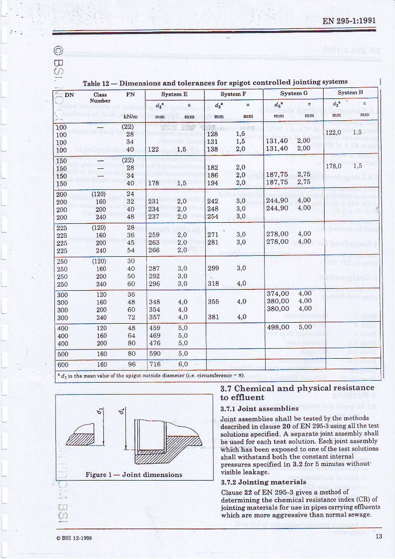
fiiite f r covers dimensional jointing systems forwhich the socket or socket fairing internal dianeter(da) is the controlling dimension. Table 12 coversdimensional jointing systems for which the spigotoutiide diameter (ds) is the controlligg dimF.q"sjon(see Figure 1). Pipes and frttings of the samedimensional jointing system of the same nominalsize and the same class are directlyinterchangeable. Other jointing systems aie
'
permitted provided that the pipes and frttings aisocomply with 2.2 and provided the joint assembliescomply with 3.1 where appropriate and 3.3 to 3.5,3.? to 3.9. Manufacturers ofjointing systems withdimensions dilTering from Tables 11 and 12 shall,when necessary, offer adaptors to connect to thedimensional requirements of systems given in' I ab les l 1 ano r z .
|..'-,:
@ BSI 12-1999 1 l
EN 295-1:1991
Table 11 - Dimensions and tolerances fo" "o"k"t "oottoll"'l
1380,0 0,5f zoo-L 60" do i" th" int att"l diamet€r of socket or socLei faidng'
NOTE d4 is measured within 20 mm of the shoulder of the socket'
@
."..
EN 295-1:1991
3.7 Chemical and physical resistanceto effluent3.7.1 Joint assernblies
Joint assemblies shall be tested by the methodsdescribed in clause 2O of EN 295-3 using all the testsolutions specfied. A separate joint assembly shallbe used for each test solution. Each joint assembly*hiih has been exposed to one ofthe test solutlonsshall withstand both the constant internalpressures specified in 3.2 for 5 minutes without'visible leakage.
3.7.2 Jointing naterials
Clause 22 of EN 295-3 gives a method ofdetermining the chemical resistance index (CR) ofjointing materials for use in pipes carrying effluentswhich are more aggressive than normal sewage.
Table 12 - Dimensions and tolerances for spigot controlled jointing systems
:: DN class FN! . : Numbe t
:. - kN/m
Sy6tem E Systed F System G SystemH
dt^
mm mta lntrt mm mm tllm mm mm
100100100100
(22)28
40
: . :'.::,,
r22 1,5
::'.:r281 3 1138
I , O
131,40131,40
2,002,00
122,0 1,5
150110150150
(22)28
40 1 , 5178
L82 2,O186 2,O194 2,0
t87,75 2,75L87,75 2,75
1?8,0 1,5
200200200200
(120) 24160 32200 40240 48
237 2,O234 2,0237 2,O
242 3,0248 3,0254 3,0
244,90 4,00244,90 4,00
225
225225
(120) 2a160 36200 45240 54
2 ,02,O2.0 .
259263266
z7r 3,028t 3,0
27 A,OO 4,0027 8,OO 4,00
250250250250
020) 30160 40200 50240 60
3 ,03,03.0
287292296
3,0
4,0
259
3 1 8
300300300300
I20 36160 4a200 60240 72
348 4,0354 4,O357 4,0
355 4,0
381 4,0
37 4,OO 4,00380,00 4,00380,00 4,00
400400400
720 48160 64200 80
459 5,0469 5,0476 5.0
498,00 5,00
500 80r60 5 , 0590
600 96160 716 6,0
"l/'-1 I
7-)"l
FiEure I - Joint dimensions
o BSI 12-1999
EN 295-1:1991
3.8 Therrnal cYcling stabilitY
Joint assemblies shall withstand cyclic temperature
changes between- 10 "C and + 70 oC without visible
impairment when tested in accordance with
clause 2L.1 of EN 295-3'
Finally, a water tightness test as specilied in 3'2'1
shall be carried out.
3.9 Long-term therrnal stabilitY
Joint assemblies shail withstand a long-terni
thermal stability test in accordance with clause 21'2
ofEN 295-3 for seven days at a temperature
of45 "C + b .C - 0 "C.
Finally, a watertightness test as specfied in 3'2'1
shall be carried out.
4 Sampling for tests
Sampling for pipes, Iittings and joint assemblies is
given in EN 295-2.
5 DesignationThe following shall be used for the designation ofpipes and fittings:
Block I Denomination
Block 2 EN 295-1
Block 3 Individual item block
Block 3.1 Nominal size
Block 3.2 StrengthBlock 3.3 Jointing sYstem
Example 1: PIPE EN295' 1-DN300-FN48-C
Example2: BEND4SEN295'1-DN200-FN40-E
6 Marking6.1 All pipes and fittings shall be marked with:
- EN 295-1- CE symbol (to be added after confirmation ofthe EC Council Regulation on the use of theCE symbol)- identification iymbol of the third partycertification bodY- manufacturet's identification- date of manufacturing- nominal size (DN...)- dimensional jointing system
In additi.on pipes shall be marked with:- crushing strength in kN/m- bending moment resistance in kN m if
I applicable
This marking shall preferably be impressed before
firing, or, if t'Lis is not possible, shall be indelibly
done after frring on each pipe and fitting'
In add.ition bends and junctions shall be marked to
indicate the angle'
6.2 AII flexible nechanical joints supplied as
separate cornponents shallbe marked to identify the
manufacturer and the dimensional jointing system'
Connectors andadaptors shallbe marked to identify
the dimensional jointing systems which they are
designed to connect.
6.3 Products shall be marked with the nurnber of
this stanclard only if certified in accordance with
clause ? by a third party certification body'
7 Quality Assurance
Quality Assurance shall be in accordance with
EN 295-2.
BS EN 295-1:1991
National appendix NA (informative)The United Kingdom participation in the preparation of this European Standard was entrusted by theTechnical Committee for Waste Water Engineering 8/505 to Subcomrnittee 8/505/2, upon which thefollowing bodies were represented:
British Ceramic Research LimitedClay Pipe Development Association LimitedDepartment ofthe Environment (Pioperty Services Agenc/Department of TransportFederation of Civil Engineering ContractorsInstitution of Civil EngineersInstitution of Water and Environmental ManagementSociety of British Water IndustriesWater Services Association of Ensland and Wales
o BsI 12.t999 1 0
BSI389 Chtswick HiSh RoadLndonW4,lAL
BSI - British Standards Institution
BSI is the indeperdent natiorul body re+onsible for prcparing British Standards lt
;;G $l; IJii;;* on stanaaros in ri:rope and at the int€rnational Iei€l It is
incorporared by RoYal Charter
Revisions
Brifish Startdads arc updated by amendnent or revision Users of British Standards
should make sure that they possess the latest amen&nents or editiors'
It is the constant aim of BSI to impmve t}e qualtty of orr products amd sewices We
*"-"fa L" g"rr"t rf if uryone finding an iruccuracy or ambiguily while using this
e.iti.L i'gfiau,6 *o,nd inform th;Secxetary of t1e technicat commitee resporsible,
the identity of *trich can be formd on the inside front cover' Tbl 020 8906 9000-
Far 020 8996 7,100.
BSI offers members an individual updating service catled PLUS which ensures that
subscribeF autornatically receive the latest editions o! standards'
Buying standards
Orders for all BSI, intemational and forcign standards publicatio-ns-should be
In rcsporise to odels for int€mational standards, it is BSI policy to supply the BSI
i*pi"ii""t"u"" of those tlnt have been published as British Standards' unless
ottrerwise requested
Information on st,andsrds
BSI provides a wide range of information on national, European ard international
standards through its Liirary and its'Ibclurical HeIp to Exporters Service' Variors
BSI eleclronic iiformation services are also available which give details on all itsproducts and seFices. Contact the Information Centre Tbl 020 8996 ?111'
Fbc 020 8996 7048.
Sutiscribing members of BSI are kept up to date with stan&rds developments and
receive sub=stanfial discorme on the pr:rctrase price of standards For details of
these and other benefits contact MembeFhip Administ-iition Tbl: 020 8996 7002'
Fax 020 8996 7001.
Coptright
Copyright subsiSts in a[ BSI publicatiors. BSI also holds the copyrighq in the UK of
tire iui'tcatiors of the intenitional standardization bodies Except as permitted
rmder the Coprright, Designs and Pat€nfs Act 1988 no exb'act rnay be reproduced,stored in a retieval system or Fansmited in any form or by arry means - elechonic'photocopying, recording or otherwise - without prior written permission from BSI'
This does not preclude the ftee use, in tlte course of irnplementing.the standard' of
necessary detils such as symbols, and size, type or grade designations' If these
details are t,o be used for any other purpose tlBn implementation then the prior
wdtten permi.*sion of BSI must be obtained.
If permission is grant€d, the temls rrlay indude royalty payments or a licensingagieement. Details and advice czn be obtained from the Copyright Manager'TbL 020 8996 7070