BSE Public CPD Lecture – Distributed Energy Systems on the Landscape - Few Large and Many Small on 28 September 2010 A public CPD lecture was held on 28 September 2010 (Tuesday) delivered by two Visiting Chair Professors - Professor Adrian Bejan jointly appointed by BSE and ME; and Professor Sylvie Lorente appointed by BSE. The topic was Distributed Energy Systems on the Landscape - Few Large and Many Small. Over 200 participants attended this lecture, jointly organized by the Department of Building Services Engineering and Alumni Association of Building Services Engineering. Powerpoint file of the CPD lecture Professor Bejan is jointly appointed by BSE department and ME department as a Visiting Chair Professor of Engineering. He is currently a Professor at Duke University, USA. He has published 500 peer-reviewed articles. His research covers a wide range of topics in thermodynamics, heat transfer, fluid mechanics, convection and porous media. More recently, he developed the constructal law of design in nature. He is ranked among the 100 most highly cited authors worldwide in engineering (all fields, all countries), the Institute for Scientific Information, 2001. Professor Lorente is appointed by BSE department as a Visiting Chair Professor of Engineering. She got her BS, MS and PhD from INSA Toulouse, France. Her research interests encompass vascularized materials, constructal theory, porous media, fluid mechanics, heat and mass transfer. Presentation by Professor Bejan Presentation by Professor Lorente
Transcript
BSE Public CPD Lecture – Distributed Energy Systems on the Landscape - Few Large and Many Small on 28 September 2010 A public CPD lecture was held on 28 September 2010 (Tuesday) delivered by two Visiting Chair Professors - Professor Adrian Bejan jointly appointed by BSE and ME; and Professor Sylvie Lorente appointed by BSE. The topic was Distributed Energy Systems on the Landscape - Few Large and Many Small. Over 200 participants attended this lecture, jointly organized by the Department of Building Services Engineering and Alumni Association of Building Services Engineering.
Powerpoint file of the CPD lecture Professor Bejan is jointly appointed by BSE department and ME department as a Visiting Chair Professor of Engineering. He is currently a Professor at Duke University, USA. He has published 500 peer-reviewed articles. His research covers a wide range of topics in thermodynamics, heat transfer, fluid mechanics, convection and porous media. More recently, he developed the constructal law of design in nature. He is ranked among the 100 most highly cited authors worldwide in engineering (all fields, all countries), the Institute for Scientific Information, 2001. Professor Lorente is appointed by BSE department as a Visiting Chair Professor of Engineering. She got her BS, MS and PhD from INSA Toulouse, France. Her research interests encompass vascularized materials, constructal theory, porous media, fluid mechanics, heat and mass transfer.
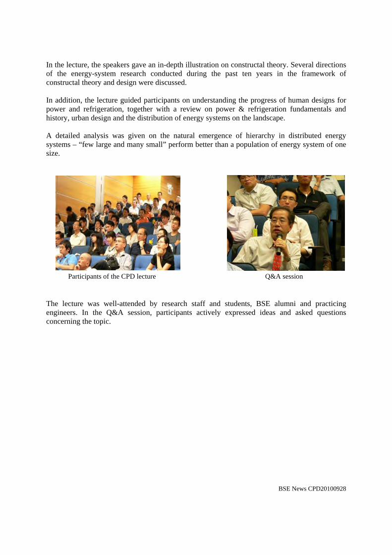
Presentation by Professor Bejan Presentation by Professor Lorente
In the lecture, the speakers gave an in-depth illustration on constructal theory. Several directions of the energy-system research conducted during the past ten years in the framework of constructal theory and design were discussed. In addition, the lecture guided participants on understanding the progress of human designs for power and refrigeration, together with a review on power & refrigeration fundamentals and history, urban design and the distribution of energy systems on the landscape. A detailed analysis was given on the natural emergence of hierarchy in distributed energy systems – “few large and many small” perform better than a population of energy system of one size.
Participants of the CPD lecture Q&A session The lecture was well-attended by research staff and students, BSE alumni and practicing engineers. In the Q&A session, participants actively expressed ideas and asked questions concerning the topic.
BSE News CPD20100928
www.constructal.org
Adrian BejanDuke University
USA
Distributed Energy Systems on the LandscapeFew Large and Many Small
Sylvie LorenteUniversity of Toulouse, INSA
France
*A. Bejan and S. Lorente, Design with Constructal Theory (Wiley, 2008)
www.constructal.org
“Design in Nature” is flow
“The design” vs. “to design”
“Design” unites
AnimateInanimate2
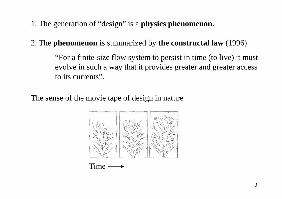
1. The generation of “design” is a physics phenomenon.
2. The phenomenonis summarized bythe constructal law(1996)
“For a finite-size flow system to persist in time (to live) it must evolve in such a way that it provides greater and greater access to its currents”.
The senseof the movie tape of design in nature
Time
The senseof the movie tape of design in nature
3
W ~ MgLµ
fW = ηm HV
4
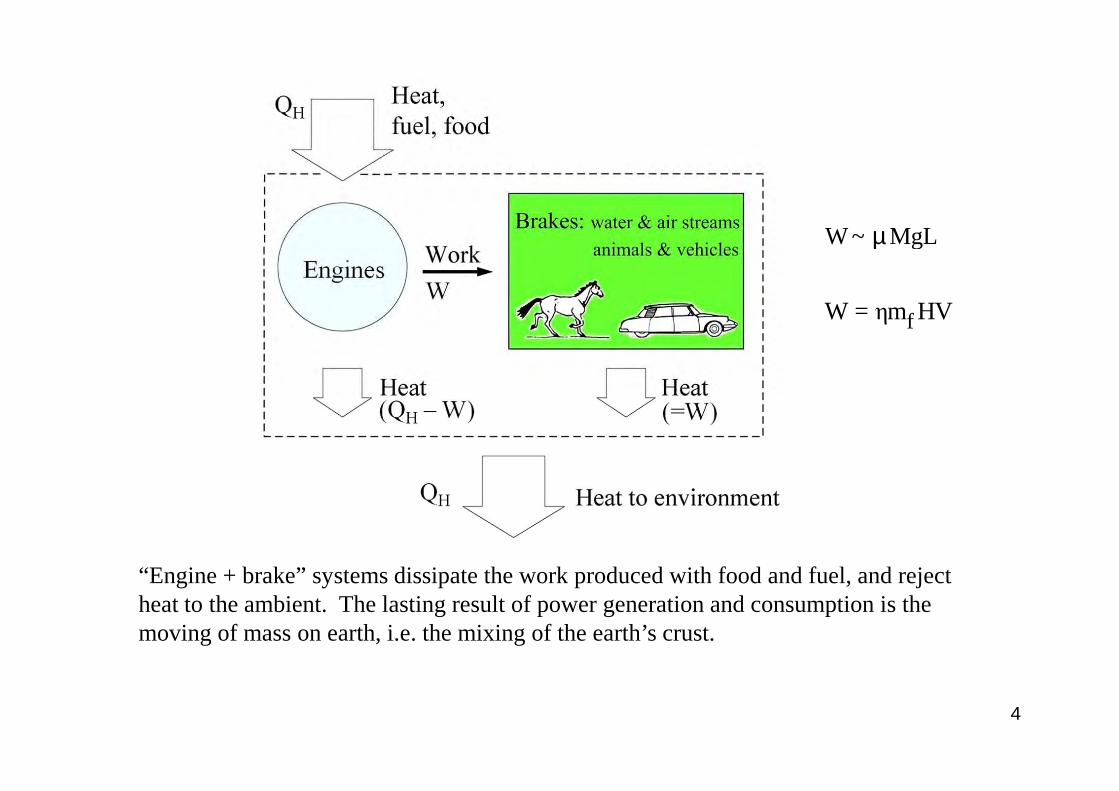
“Engine + brake” systems dissipate the work produced with food and fuel, and reject heat to the ambient. The lasting result of power generation and consumption is the moving of mass on earth, i.e. the mixing of the earth’s crust.
Fuel consumption
fµMgLm =ηHV
5
HQ&
HW = ηQ , whereη is the 'first law' efficiency of the engine.&&
fm .&The heating is proportional to the fuel flow rate
The power output isThe power is proportional to the . For more power, we need more fuel consumption and higher efficiencies.
W& fmη &
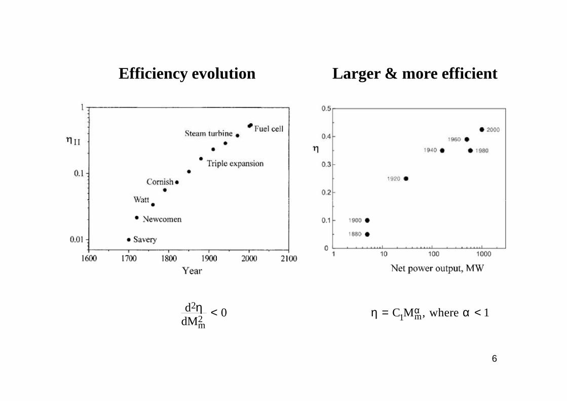
Efficiency evolution Larger & more efficient
6
2
2m
d 0dM
η < m1C M , where 1αη = α <
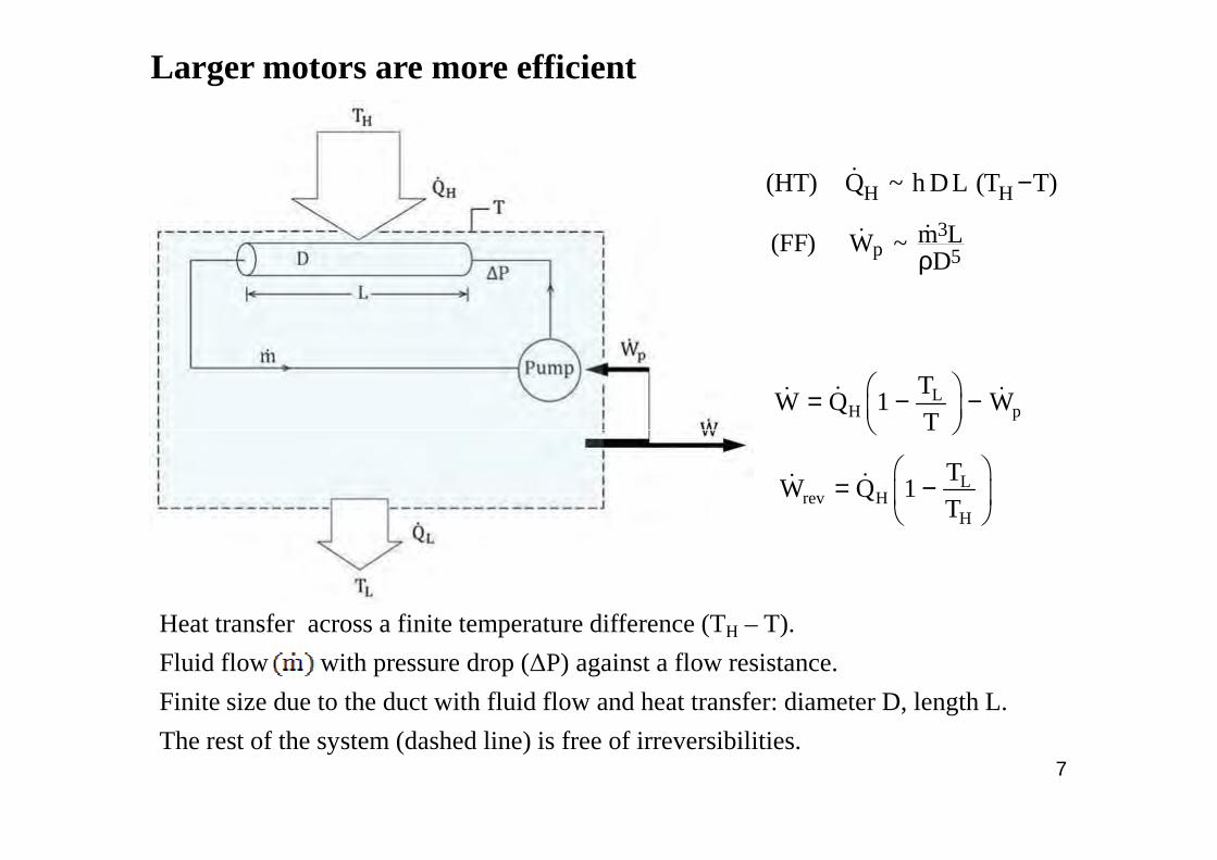
Larger motors are more efficient
H H(HT) Q ~ h DL (T T)−&
3p 5
m L(FF) W ~Dρ&&
LH p
TW Q 1 W
T = − −
&& &
7
Heat transfer across a finite temperature difference (TH – T).
Fluid flow with pressure drop (∆P) against a flow resistance.
Finite size due to the duct with fluid flow and heat transfer: diameter D, length L.
The rest of the system (dashed line) is free of irreversibilities.
T
Lrev H
H
TW Q 1
T
= −
&&
IIrev
W
Wη =
&
&
1/ 3
scaleM(D,L) ~ L ~
ρ
2 / 3 4 / 3II HT FF1 C M C M− −η = − −
2 / 3L H
HTH H L
T QC ~hT (T T )
ρ−& 1/ 3 3
FFrev
mC ~W
ρ &
&
The approximation
matches
kII 21 C M −η = −
m1C Mαη =
8
H H LhT (T T )− revW&
when
Conclusion
II
L H
1 k1 T /T
− ηα = −
kα ≤
Power generated by one power plantW = ηQ
Heat input, proportional to areaQ = aA, a = constant
Power spent on collecting fuel ! A · A1/2
Wnet = aAη – bA3/2
= 1 – me–nA
Optimal area size , constant
1/2netW bA
aA a= η −
1/2 nA b2A e
amn− =
9
10
11
12
Distributed energy systems
Nature � generation and use of power is distributed
Ex of the muscle:
power sources connected by 2 flow systems:
- tissues that generate the movement
- network that feeds and cleanses
13
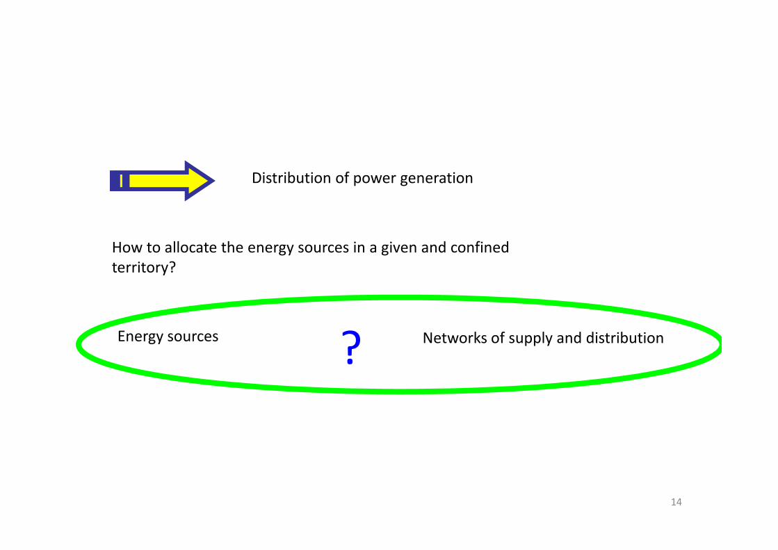
Distribution of power generation
How to allocate the energy sources in a given and confined
territory?
14
territory?
Energy sources Networks of supply and distribution?
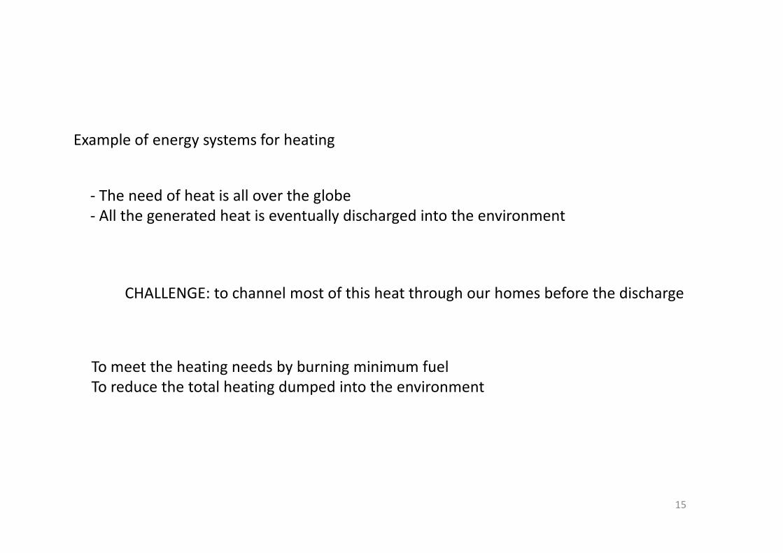
Example of energy systems for heating
- The need of heat is all over the globe
- All the generated heat is eventually discharged into the environment
15
CHALLENGE: to channel most of this heat through our homes before the discharge
To meet the heating needs by burning minimum fuel
To reduce the total heating dumped into the environment
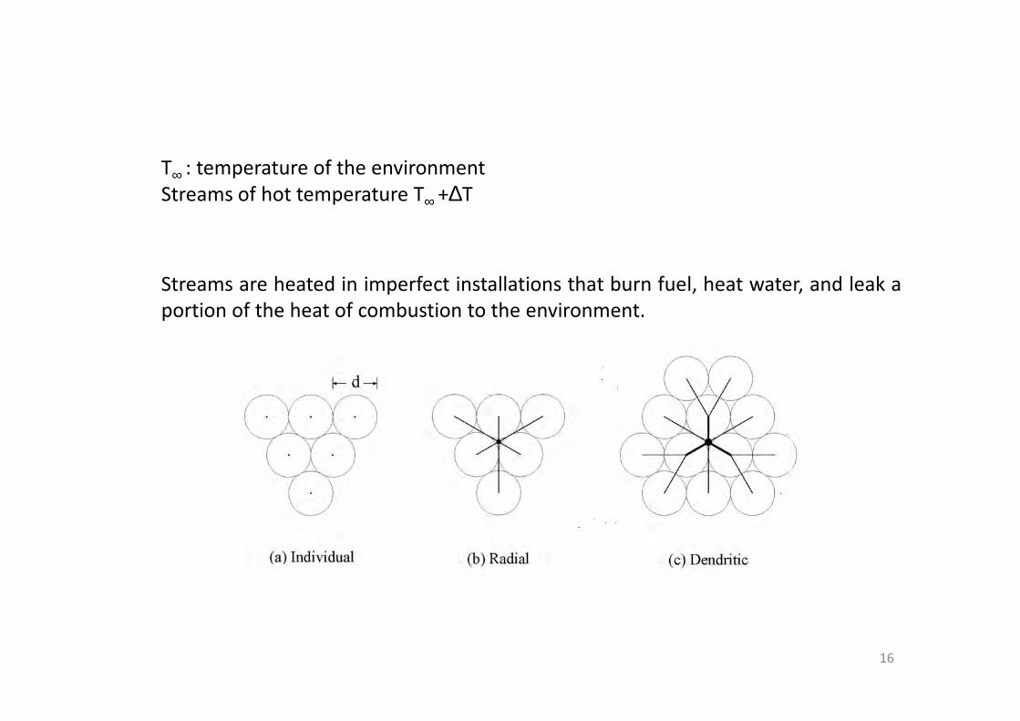
T∞ : temperature of the environment
Streams of hot temperature T∞ +∆T
Streams are heated in imperfect installations that burn fuel, heat water, and leak a
portion of the heat of combustion to the environment.
16
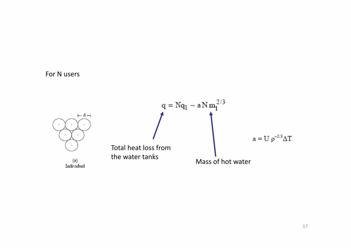
For N users
17
Total heat loss from
the water tanksMass of hot water
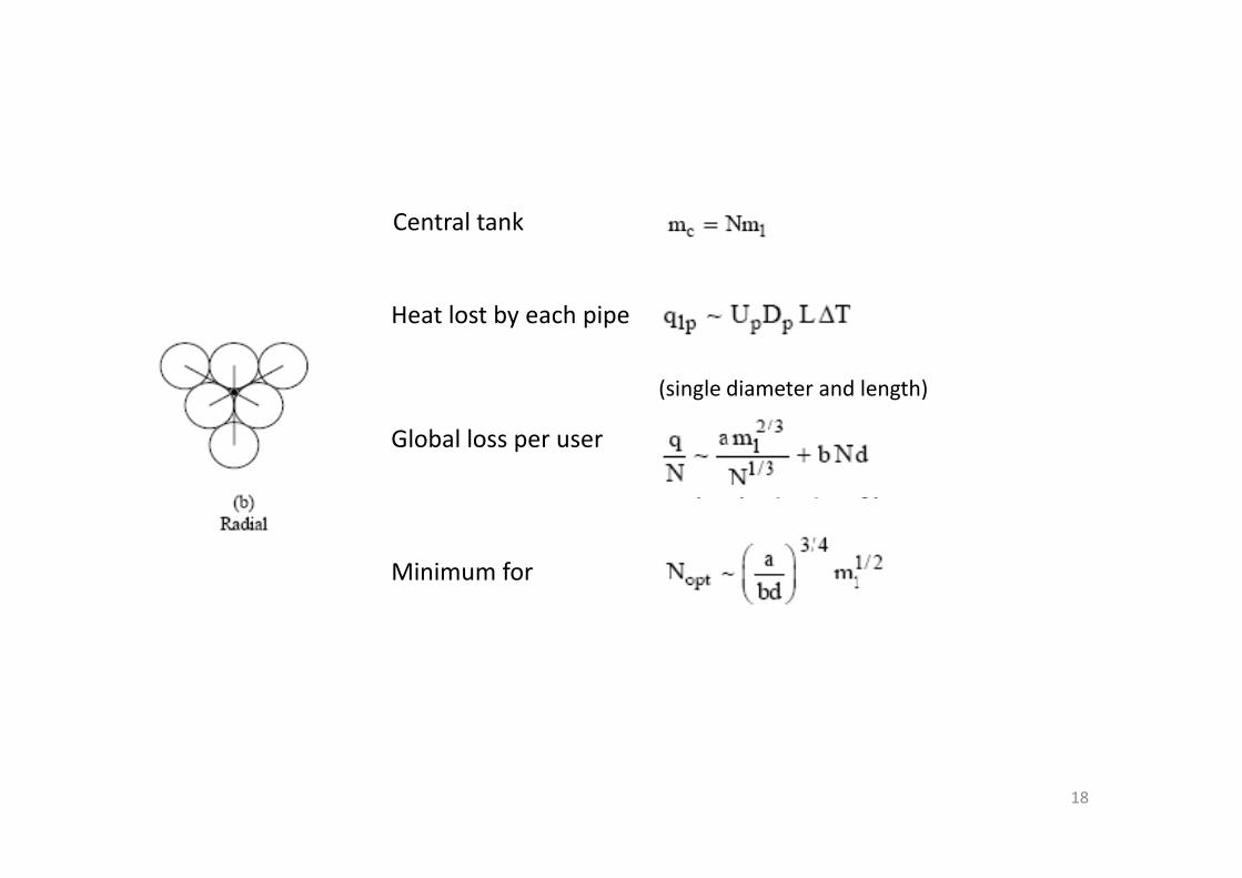
Central tank
Heat lost by each pipe
(single diameter and length)
Global loss per user
18
Global loss per user
Minimum for
Small m1: individual heaters
Above a critical size:
centralized water heating
19
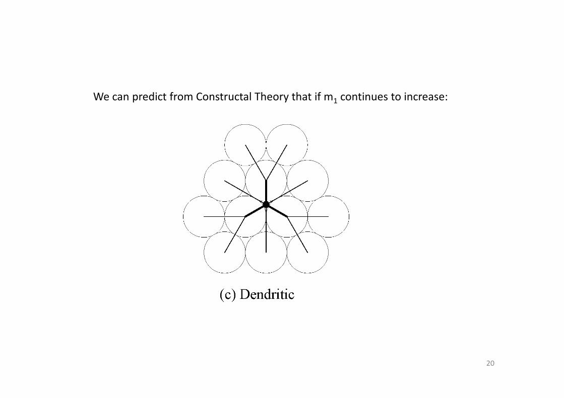
We can predict from Constructal Theory that if m1 continues to increase:
20
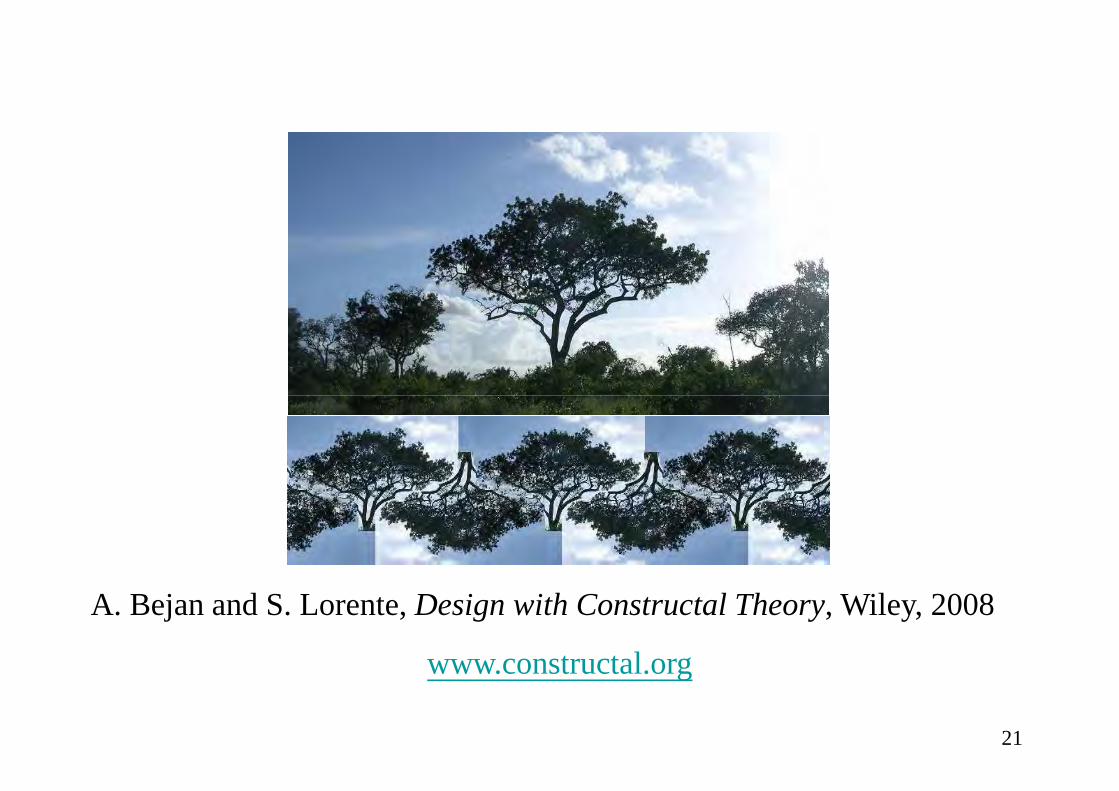
A. Bejan and S. Lorente, Design with Constructal Theory, Wiley, 2008
www.constructal.org
21
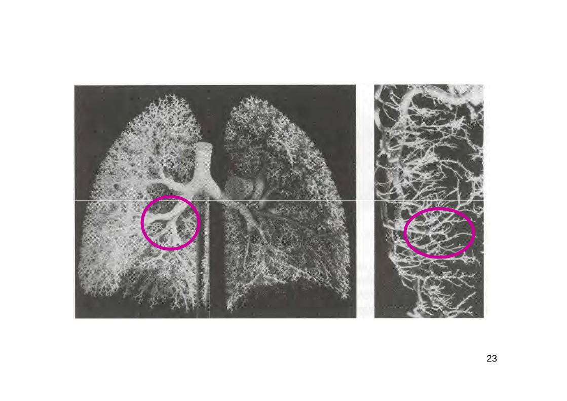
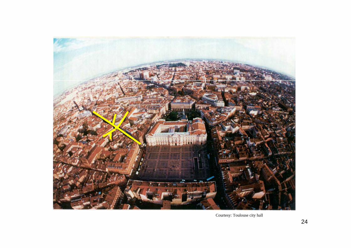
Tree architectures
Trees between a point and a circle
everywhere in nature and engineering
22
23
Courtesy: Toulouse city hall
24
Introduction
Complex flow structures with multiple scales: tree-shaped networks
Purpose to make a flow connection between one point and an infinity of pointsone point and an infinity of points
The flow resistances cannot beeliminated. They can be rearranged, assembled ...
To minimize their influence onperformance = optimization
25
best architecture: tree-shaped design
tree = geometric form deduced from a principle
Shape(or geometry) is the result ofthe minimization of imperfections, orthe optimal distribution of imperfections.
26
objectives To deliver a fluid from a source to a given number of outlets
Tree-shaped networks in a disc-shaped body
objectives
constraints Disc-shaped area Number of outletsTotal volume of the tubes
to a given number of outlets (users)
Minimum ∆P
27
L1
L2
2 levels of pairingN = 12 outlets
L0
αβγ
28
4i
i
i
i
D
L128
m
P
πν=∆
&
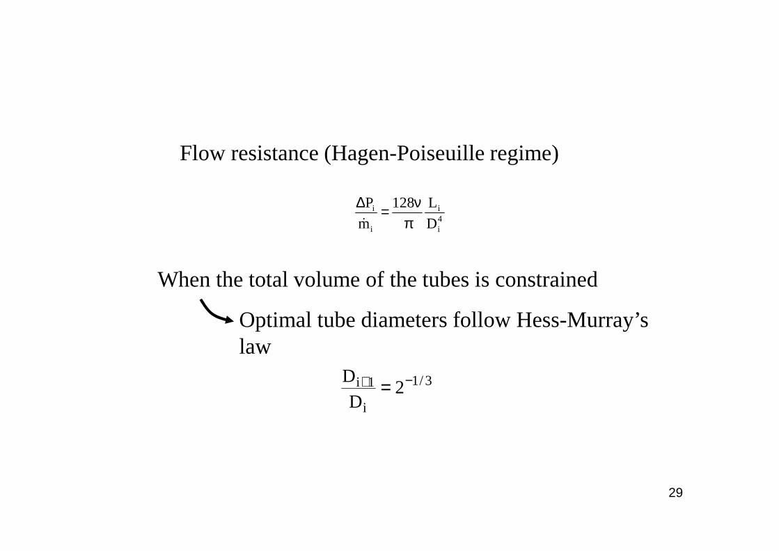
Flow resistance (Hagen-Poiseuille regime)
When the total volume of the tubes is constrained When the total volume of the tubes is constrained
Optimal tube diameters follow Hess-Murray’s law
3/1
i
1i 2D
D −+ =
29
First step
10 PPP ∆+∆=∆
L0 and L1 are expressedusing the angles α and β
0P =∆∂
Leads to
α/2
α /4
β
R
L1
L0 ∆ P75°
f²V
R8
mP 3
πν=∆&
0P =
β∂∆∂
Leads to
β=37.47°
With f a dimensionless resistance factor depending on tube lengths
Finally
30
We obtain the connecting angles
The shape of the network is the result.
(48 outlets)
It is « given » by the angles.
31
Resistancefactor
32
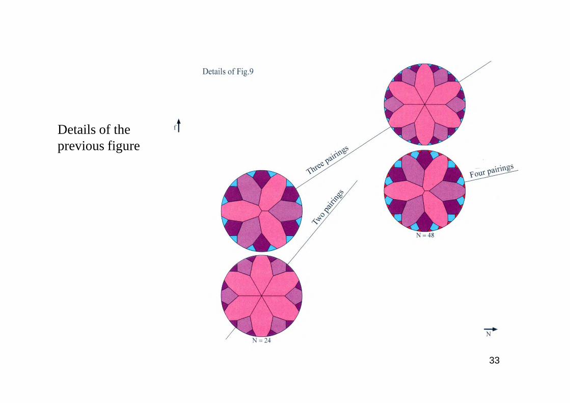
Details of theprevious figure
33
When optimized complexity is beneficial
N = constantpairing is a useful feature if N sufficiently large
N increases the level N increases the level of pairing increases
complexity increases
N constant
34
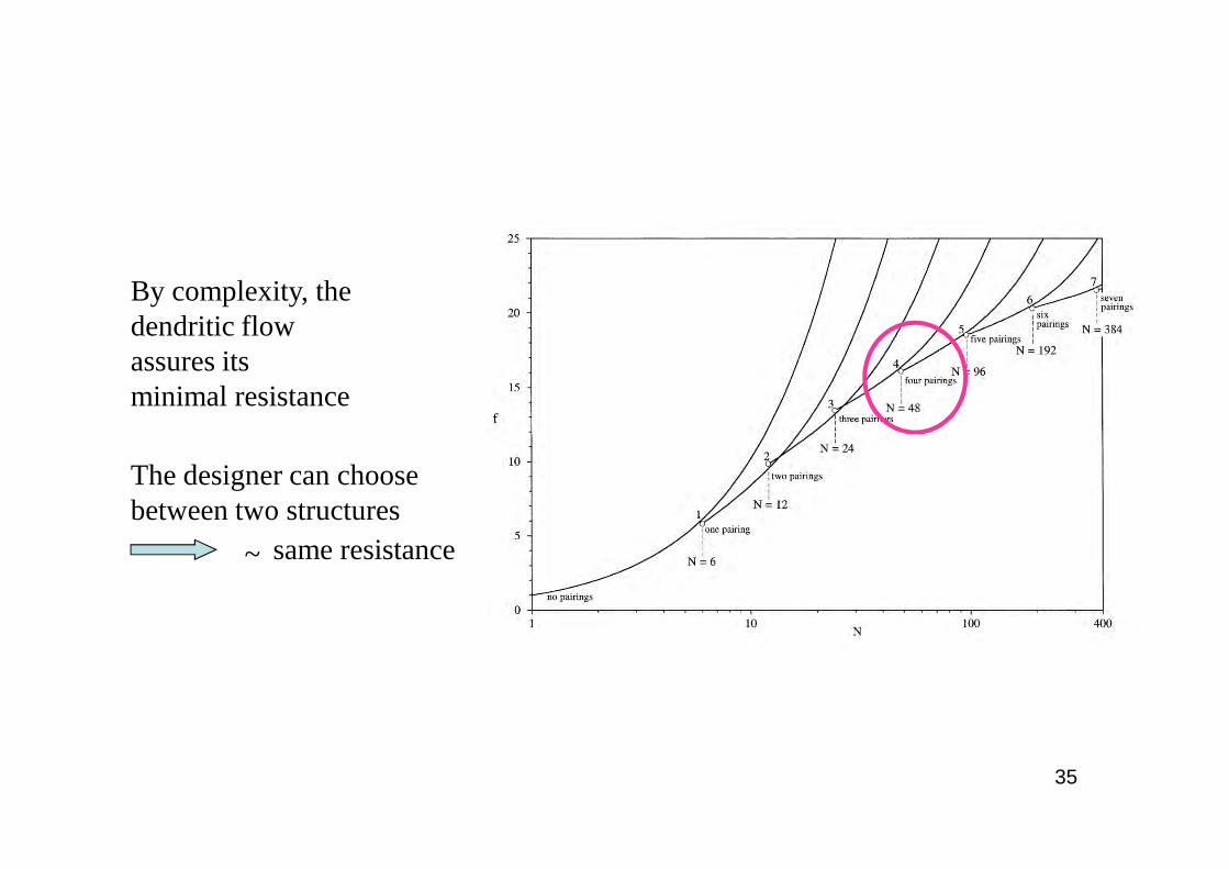
By complexity, the dendritic flowassures itsminimal resistance
The designer can choose between two structures
~ same resistance
35
Urban Networks
Maximum delivered temperatureMinimum pumping power
objectives
Tree-shaped networks of insulated pipes for the distribution of hot water uniformly over a given territory (area A)
36
Minimum pumping powerobjectives
constraints Total amount of insulationTotal volume of the pipes
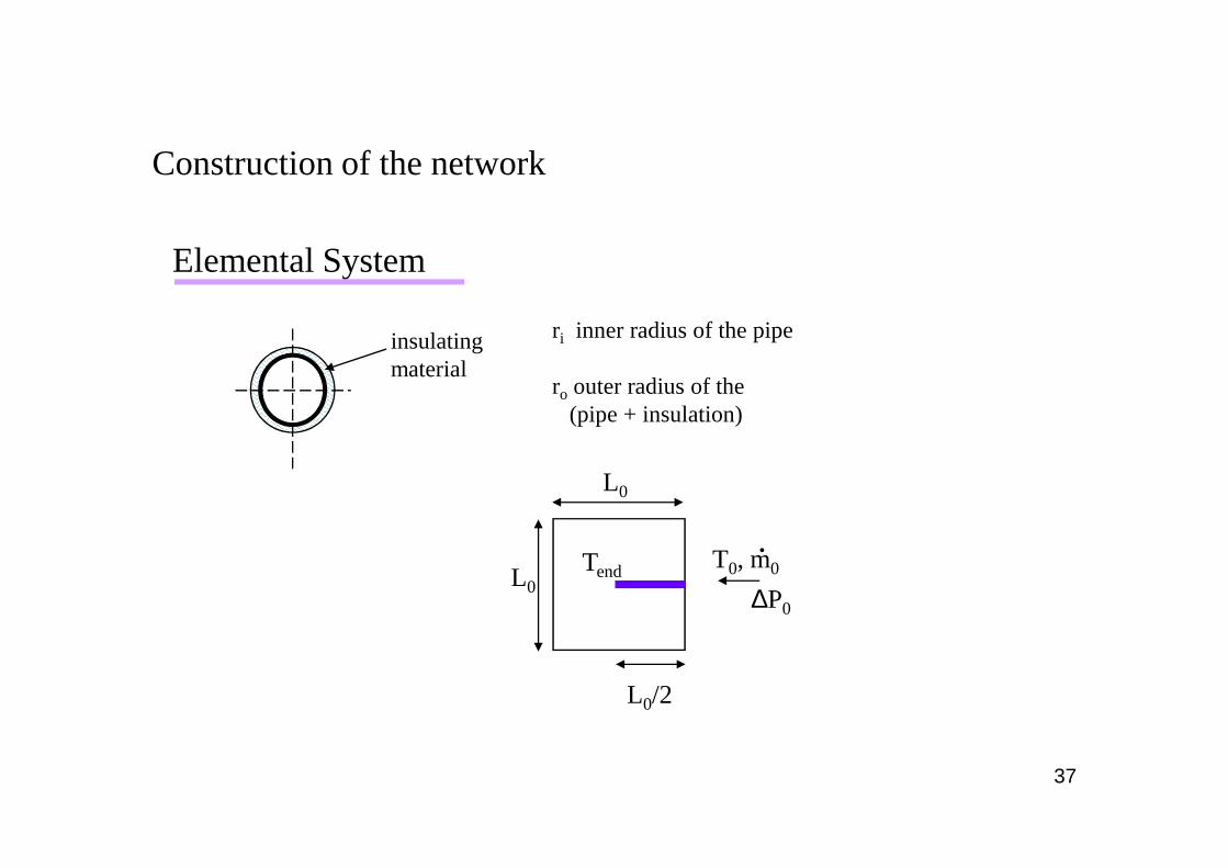
insulating material
ri inner radius of the pipe
ro outer radius of the(pipe + insulation)
Elemental System
Construction of the network
37
Tend T0, m0.
∆P0
L0
L0
L0/2
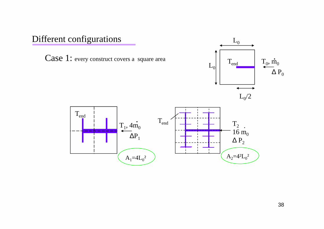
Different configurations
Case 1: every construct covers a square area
Tend .
Tend T0, m0.
∆ P0
L0
L0
L0/2
38
Tend T2
16 m0
∆ P2
.
Tend
T1, 4m0
.
∆P1
A1=4L0² A2=4²L0²
Case 2: the new construct is obtained by pairing the previous ones
A1=2L0²
Tend T0, m0.
∆ P0
L0
L0
39
L0/2
T2, 4m0
Tend.
∆ P2
A2=22L0²
.
Tend
A4=24L0²
T4
16 m0
∆ P4
Total volume occupied by the ducts
objective: minimization of the pressure drops
minimization of pumping powerFluidMechanicaspect
Total amount of insulation wrapped around the pipes
Constraints
40
Total amount of insulation wrapped around the pipes
objective: minimization of the heat losses
maximization of the temperature
of the hot water received by the end user
Heat Transfer aspect
Pressure drops and heat losses are minimizedat every step
Set of equations:
Fluid Mechanic aspect
METHOD
41
fully turbulent flow (rough)
∆P CL m
ri0
0 02
520
= &elemental system
∆P CL m
ri= & ²
5
example of case 1:
1st construct T1, 4m0
.
∆ P1
Tend
42
∆P CL m
rCL
m
rC
L m
ri i i1
0 05 0
05
0 02
524 2
21 1 0
= + +( & )² ( & )² &
∆P CL mr ri i
1 0 02
5 5
12 1
21 0
= +
&
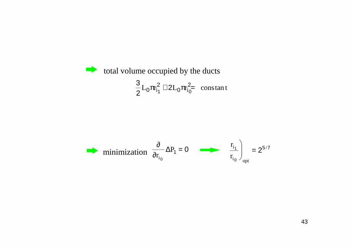
total volume occupied by the ducts
32
202
02
1 0L r L r cons ti iπ π+ = tan
43
∂∂r
Pi 0
1 0∆ =r
ri
i opt
1
0
25 7
= /
minimization
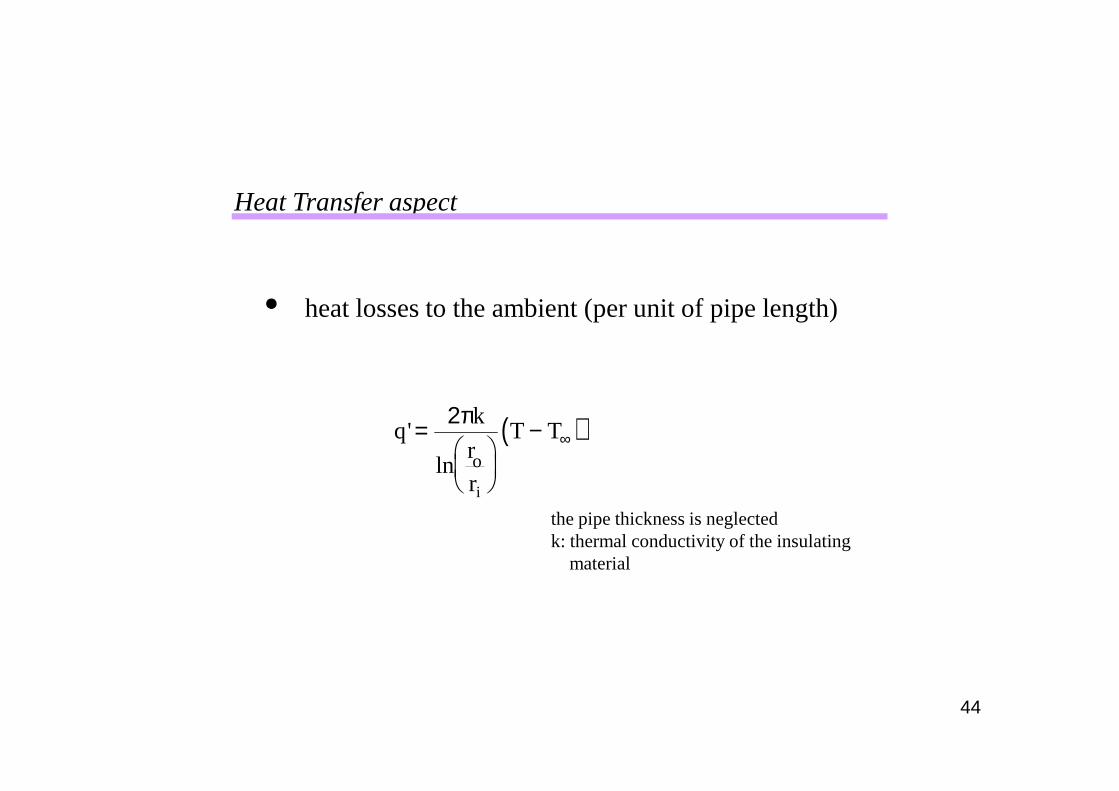
heat losses to the ambient (per unit of pipe length)
Heat Transfer aspect
44
( )qk
r
r
T Te
i
'
ln
=
− ∞2π
the pipe thickness is neglectedk: thermal conductivity of the insulating
material
o
& 'mC dT q dxp =
energy conservation
T T
T T
N
Rfinal
initial
−−
= −
∞
∞exp
lnend
45
Rr
re
i
= NkL
mCp
= 2π&
with ando
Nk
L
m Cp0
0
0
22=
π
&elemental system
"number of heat loss units"
example of case 1:
1st constructT1, 4m0
.
∆ P1
Tend
46
θ11
0
0
0
1
54
= −−
= − −
∞
∞
T T
T T
N
R
N
Rfinal exp
ln lnend
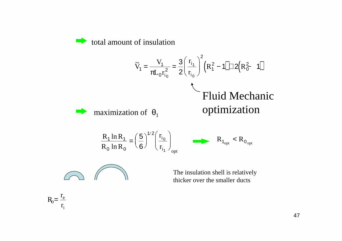
Fluid Mechanicoptimizationmaximization of θ1
( ) ( )~VV
L r
r
rR R
i
i
i1
1
02
2
12
02
0
1
0
32
1 2 1= =
− + −
π
total amount of insulation
47
R R
R R
r
ri
i opt
1 1
0 0
1 256
0
1
ln
ln
/
=
R Ropt opt1 0<
The insulation shell is relatively thicker over the smaller ducts
Rr
re
i
=o
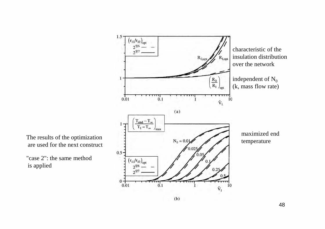
characteristic of theinsulation distributionover the network
independent of N0(k, mass flow rate)
48
maximized endtemperature
The results of the optimizationare used for the next construct
"case 2": the same methodis applied
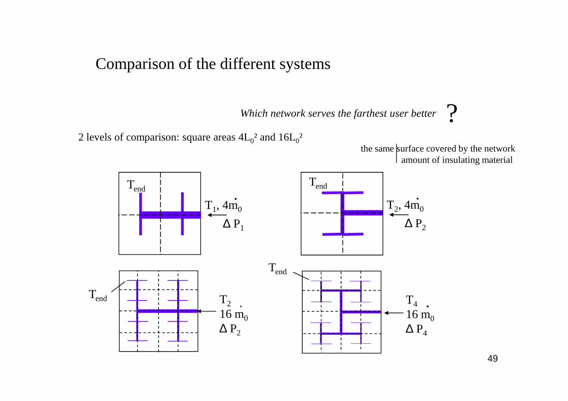
Comparison of the different systems
Which network serves the farthest user better ?2 levels of comparison: square areas 4L0² and 16L0²
the same surface covered by the networkamount of insulating material
Tend
T , 4m.
T , 4m
Tend.
49
T1, 4m0
.
∆ P1
Tend T2
16 m0
∆ P2
.
T2, 4m0
.
∆ P2
Tend
.T4
16 m0
∆ P4
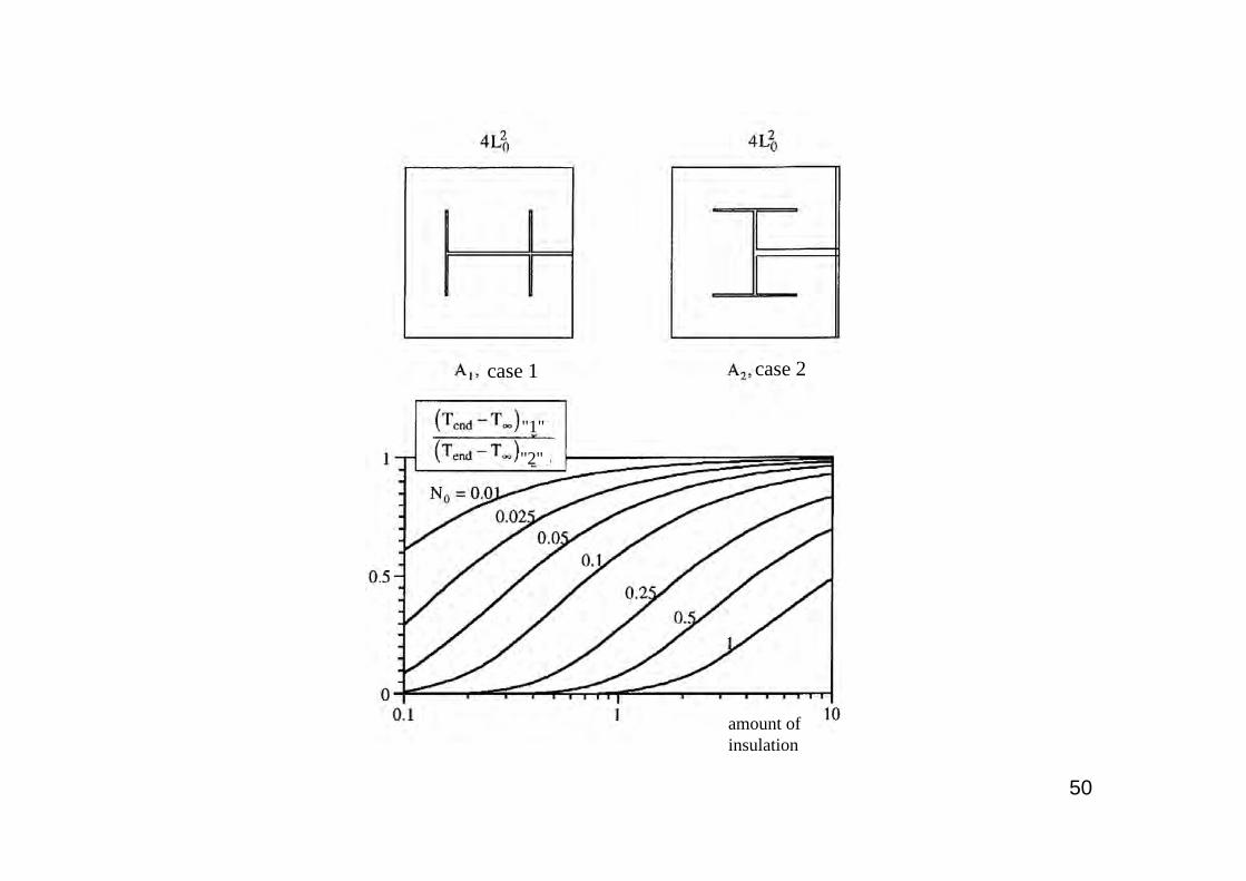
case 1 case 2
"1"
50
"2"
amount of insulation
case 1
"Case 2" performs best Tend
is higher. The difference decreases as the structurebecomes more complex
"Case 2" each user receives case 2
51
"1"
"2"
amount of insulation
"Case 2" each user receives hot water at the same temperature
The addition of new users to an existing network
Tend
T1, 4m0.
∆ P1
« one-by-one » design lessperformant than theconstructal one.But, the gap shrinks forlarger structures.