30
BSI TR-03105 Part 4 Test Plan for ICAO-compliant Proximity Coupling Devices (PCD) on Layers 1-4

BSI TR-03105 Part 4
Test Plan for ICAO-compliant Proximity Coupling Devices (PCD) on Layers 1-4

Document history
Version Date Editor Description
1.0 2006-03-30 BSI Initial release of Edition 1
2.0 2008-04-15 BSI Initial release of Edition 2
2.2 2010-03-17 BSI Update to Edition 2
3.0 2016-11-04 BSI Initial release of Edition 3
Federal Office for Information SecurityPost Box 20 03 63D-53133 BonnInternet: https://www.bsi.bund.de© Federal Office for Information Security 2016

Table of Contents
Table of ContentsDocument history.............................................................................................................................................................................. 2
1 Introduction.......................................................................................................................................................................................... 5
2 General Test Requirements............................................................................................................................................................ 6
2.1 Validity of Referenced Documents...................................................................................................................................... 6
2.2 Test Setup and Equipment...................................................................................................................................................... 6
2.3 PCD Test Features........................................................................................................................................................................ 62.3.1 Test Mode for Layer 1 and Layer 2 Tests..................................................................................................................... 62.3.2 Test Mode for Layer 3 and Layer 4 Tests..................................................................................................................... 7
2.4 Nominal Values............................................................................................................................................................................. 8
2.5 Definition of Measurement Positions................................................................................................................................ 8
2.6 Number of Test Samples........................................................................................................................................................... 9
2.7 Report................................................................................................................................................................................................ 9
3 Layer 1 Tests........................................................................................................................................................................................ 10
3.1 Alternating Magnetic Field................................................................................................................................................... 10
4 Layer 2 Tests........................................................................................................................................................................................ 11
4.1 Operating Field Strength....................................................................................................................................................... 11
4.2 Modulation Index and Waveform..................................................................................................................................... 11
4.3 Load Modulation Reception................................................................................................................................................. 11
4.4 EMD Immunity Test................................................................................................................................................................. 12
4.5 EMD Recovery Test................................................................................................................................................................... 12
5 Layer 3 Timing Tests....................................................................................................................................................................... 13
5.1 Frame Delay Time (Type A only)........................................................................................................................................ 135.1.1 Frame Delay Time PCD to PICC.................................................................................................................................. 135.1.2 Frame Delay Time PICC to PCD.................................................................................................................................. 14
5.2 Bit Boundaries (Type B only)............................................................................................................................................... 15
5.3 Start-of-Frame and End-of-Frame Timing (Type B only)......................................................................................16
5.4 Extra Guard Time (Type B only)......................................................................................................................................... 17
5.5 Timing before PICC SOF (TR0 and TR1) (Type B only)............................................................................................18
5.6 Timing before PCD SOF (TR2) (Type B only)................................................................................................................ 20
6 Layer 3 and Layer 4 Protocol Tests........................................................................................................................................... 21
Annex A Implementation Conformance Statement............................................................................................................. 22
Annex B Reader Design Types and Measurement Positions.............................................................................................23
B.1 Reader Design Type Definitions......................................................................................................................................... 23B.1.1 Type 01..................................................................................................................................................................................... 23B.1.2 Type 02..................................................................................................................................................................................... 23B.1.3 Type 11..................................................................................................................................................................................... 23B.1.4 Type 12..................................................................................................................................................................................... 24B.1.5 Type MO.................................................................................................................................................................................. 24
B.2 Measurement Positions.......................................................................................................................................................... 26B.2.1 Type 01..................................................................................................................................................................................... 26B.2.2 Type 02..................................................................................................................................................................................... 26B.2.3 Type 11..................................................................................................................................................................................... 26
Federal Office for Information Security 3

Table of Contents
B.2.4 Type 12..................................................................................................................................................................................... 27B.2.5 Type MO.................................................................................................................................................................................. 27
Reference Documentation........................................................................................................................................................... 28
Keywords and Abbreviations...................................................................................................................................................... 29
FiguresFigure 1: Measurement positions Type 11......................................................................................................................................... 26
TablesTable 1: FDT test conditions..................................................................................................................................................................... 13
Table 2: TR0/TR1 test conditions........................................................................................................................................................... 18
Table 3: TR2 coding options...................................................................................................................................................................... 20
Table 4: Volume definition Type 11 reader........................................................................................................................................ 23
Table 5: Volume definition Type 12 reader........................................................................................................................................ 24
Table 6: Measurement positions Type 11 reader............................................................................................................................. 26
4 Federal Office for Information Security

Introduction 1
1 IntroductionPassports are a key element of travels between countries. Although the individual document styles differ – depending on the issuing country – it has to be ensured that each passport's construction follows several general rules, in order to guarantee interoperability. These general rules are defined in “Document 9303”, published by ICAO (International Civil Aviation Organization).
Traditionally, passports only contained printed data (partially, in machine-readable form) but with the evolving technology of contactless smart card systems it was decided (at the beginning of the 21 st century) to allow integration of a contactless chip (together with an appropriate antenna) into the passport document. Consequently, this additional element is also defined in (an extension to) Document 9303.
The underlying technology of a so-called “ePassport” is defined in the ISO/IEC 14443 standard series (parts 1 to 4 covering aspects starting from physical characteristics up to transmission protocol definitions), extended by an application specification defined in Document 9303.
While reader devices of “traditional” (= non-electronically enhanced) passports only had to be able to optically read documents, an ePassport reader device (often called “inspection system” in this context) additionally has to be able to access the data stored on the document's contactless chip. The technology necessary to provide this functionality also is defined in the ISO/IEC 14443 standard series.
In order to ensure that given ePassport documents and reader devices match their specifications, it is of crucial importance to perform standardized tests. Especially due to the inclusion of smart card technology (which makes it necessary to test these components, too), the specification “TR-03105” was issued by the BSI (initially, in 2005).
BSI TR-03105 is a series of documents which is split up in general requirements (introduction and Part 1), card-testing (Parts 2 and 3.x), and reader-testing (Parts 4 and 5.x) aspects. Both card-testing and reader-testing topics consist of lower-layer (Parts 2 and 4) and application-layer (Parts 3.x and 5.x) parts.
Generally, the TR-03105 documents form the basis of certification testing for German ePassports (and, as introduced later, German eID cards) documents and readers. But they can also be applied to foreign ePassports and eID products (as long as it is guaranteed that they are constructed in a standardized way) – thus giving the TR-03105 an importance beyond the German market.
Within this specification, BSI TR-03105 Part 4, the focus is on lower-layer (meaning ISO/IEC 14443-1 .. -4) reader device testing. Both earlier editions of this specification were based on ISO/IEC 10373-6:2001 (the first edition of the general test standard for ISO/IEC 14443-compliant products) but this third edition is based on the new ePassport testing standard ISO/IEC 18745-2:2016.
The update of TR-03105 Part 4 was necessary in order to ensure that all current technology – ISO/IEC 14443 significantly changed and expanded during the past years – is still covered by this test specification. While former editions contained many unique test case definitions (which were not covered by ISO/IEC 10373-6 at that time), the new third edition is mainly referring to matching ISO/IEC 18745-2:2016 test scenarios (with only few own definitions remaining) in order to ensure a high compatibility to this standard.
Federal Office for Information Security 5

2 General Test Requirements
2 General Test Requirements
2.1 Validity of Referenced Documents
In order to prevent potential conflicts caused by updates of any of the referenced documents (see Annex), no modifications or extensions of these documents occurring after October 01, 2016 are taken into account. This especially holds for (yet unpublished) amendments to specifications which would have automatically become applicable right after publication otherwise.
2.2 Test Setup and Equipment
In general, the definitions given in ISO/IEC 18745-2:2016, Chapters 6.1 (“General test requirements”) and 6.1.1 (“Test setup”) shall be used without modifications.
If a certain test case requires a different setup, it shall be specified in the context of the individual test case definition.
2.3 PCD Test Features
In order to ensure that all test scenarios defined in this document can be performed without complications it is often not sufficient if the DUT functions in its “normal” operation mode. Thus it is required that the DUT is equipped with certain test modes.
As the test mode requirements significantly differ between Analog (Layers 1 and 2) and Digital (Layers 3 and 4) parts, they shall be separately presented in the following.
2.3.1 Test Mode for Layer 1 and Layer 2 Tests
It is not defined how the following characteristics are to be provided by the DUT – it may either be with an application running on a separate PC which controls (via an arbitrary interface) the reader module or it may also be installed on the reader itself (provided that the device has sufficient capabilities, e.g., a graphical user interface). The provision of the test interface is the task of the DUT provider.
The Layer 1/2 test mode must meet the following requirements:
• The DUT has to be able to send an unmodulated carrier in order to enable field strength measurements.
• The DUT must be able to send REQA/REQB (or WUPA/WUPB) commands at all supported bit rates1 in order to enable waveform and reception tests.
• The test interface must be able to display responses to REQA/REQB (or WUPA/WUPB) commands at all supported bit rates – this capability is needed for reception tests where a feedback is required in order to determine if a PICC response was detected by the DUT or not.
1 Usually, REQA/REQB (or WUPA/WUPB) must only be sent at default bit rate (fc/128). For the purpose of testing, they shall (exceptionally) also be available at (all supported) higher bit rates.
6 Federal Office for Information Security

General Test Requirements 2
2.3.2 Test Mode for Layer 3 and Layer 4 Tests
ISO/IEC 18745-2:2016 specifies – in Chapter 6.5 (“List of test command sequences”) - various test commands (“UT_TEST_COMMAND”) which shall be used for all tests where transitions at protocol level are made (such transitions occur within several Layer 3 and all Layer 4 tests). In general, this approach shall be followed within this document as well – but in a modified way.
The general problem with the “UT_TEST_COMMAND” approach is that it is not exactly defined how these test commands have to be provided by the DUT2. This leads to the practical problem that no unique test interface is available and a resource-consuming individual adaptation (ensuring that test system and DUT are able to correctly interact) is always required.
The definitions provided in the following take the “UT_TEST_COMMAND” approach into account but additionally define how the specified commands have to be provided (by the DUT) in practice. They may be implemented on the device itself (provided it has appropriate capabilities) or on an external control device (via an arbitrary interface to the DUT). DUT and test system only communicate via the contactless interface.
The Layer 3/4 test mode must meet the following requirements:
• In general, it is required that the DUT implements a full polling cycle for both types (A and B) – which means it must poll with REQA (or WUPA) and REQB (or WUPB) – and, after a correct ATQA/ATQB was received, it must lead the (simulated) card through all succeeding states until finally PROTOCOL state is reached. As ISO/IEC 14443-3/4 don’t give a fixed definition of such a polling sequence it is up to the DUT on how the concrete implementation is constructed (as long as it can successfully and reproducibly lead cards of both types to PROTOCOL state)3.
• Having reached PROTOCOL state (either Type A or Type B) the DUT has to provide a loopback interface which is defined as follows:
– The DUT sends a SELECT APDU of the form<PCB> [<CID>] 00 A4 04 0C 08 F0 42 53 49 20 65 50 50 00 <CRC1> <CRC2>.
– The card (simulated by the test system) either responds with<PCB> [<CID>] <<NEXT_COMMAND>>4 90 00 <CRC1> <CRC2> (loopback scenario)or <PCB> [<CID>] FF FF FF FF 90 00 <CRC1> <CRC2> (end loopback mode)
– The DUT has to react as follows:<PCB> [<CID>] <<NEXT_COMMAND>> <CRC1> <CRC2> or end communication (switch field off and restart polling cycle)
• This communication mode is continued until either the test system sends the “end loopback” frame or does not respond anymore (in this case, the DUT has to initialize the communication shutdown measures as defined in ISO/IEC 14443-4).
• In either case, the DUT is mandated to respect the block handling rules defined by ISO/IEC 14443-4 – especially regarding block numbering, chaining, handling of waiting time extensions, and error handling. These mechanisms will be used (by giving appropriate responses to DUT commands) by the test system during the Layer 4 tests.
2 It is obvious that the test commands have to be provided via the contactless interface but it additionally is required that also some trigger mechanism has to be present which allows to distinguish between sending UT_TEST_COMMAND1 and UT_TEST_COMMAND2.
3 ISO/IEC 18745-2:2016, Chapter 6.5 uses the abstract term “INITIATE_ANTICOLLISION” for this mechanism – it is described in more detail in ISO/IEC 10373-6:2016, Annexes H.1.3 and H.1.8.
4 In general, <<NEXT_COMMAND>> might be any byte array (including the empty one). Depending on the concrete scenario, it might be useful to place a formally correct Command-APDU here.
Federal Office for Information Security 7

2 General Test Requirements
The ISO/IEC command “UT_TEST_COMMAND1” will be the SELECT APDU for the loopback application itself (“00 A4 04 0C 08 F0 42 53 49 20 65 50 50 00”). This is a modification of the definition in ISO/IEC 18745-2:2016, Chapter 6.5.1.
• The fixed response to UT_TEST_COMMAND1 (“12 34 90 00”, as defined in ISO/IEC 18745-2:2016) shall not be used – as it would lead to a conflict with the loopback mechanism rules defined above. Instead, the response shall be flexibly chosen – depending on the requirements of the concrete test procedure.
In general, “UT_TEST_COMMAND2” should be similar to the command defined in ISO/IEC 18745-2:2016, Chapter 6.5.2.1 – but with some modifications in order to ensure that it is compliant with the loopback mechanism:
• UT_TEST_COMMAND2 will be (part of) the response to the SELECT loopback APDU (i.e., it will play the role of the <<NEXT_COMMAND>> defined above)5.
• Instead of using a fixed-length command (containing 255 data bytes) length and value of UT_TEST_COMMAND2 shall be flexibly chosen based on the requirements of the concrete test scenario (there are scenarios where a shorter command is more useful but a longer one might also be needed – if maximum frame sizes larger than 256 bytes have to be considered)6.
• The defined response to UT_TEST_COMMAND2 shall also be modified in order to both match (individual) test case and loopback requirements.
2.4 Nominal Values
In general, the values defined in ISO/IEC 18745-2:2016, Chapter 6.1.2 (“Values unless otherwise specified”) shall be used.
In contrast to the test temperature definition given in ISO/IEC 18745-2 (fixed range which might change on applicant's request) it is always mandatory for the applicant to define an individual temperature range. The extreme values of this range, together with room temperature, shall be used for testing.
2.5 Definition of Measurement Positions
The general requirements as given in ISO/IEC 18745-2:2016, Chapter 6.1.5 (“Definition of measurement points”) shall be used, without modifications.
As the selection of appropriate measurement positions heavily depends on the construction of the DUT, it is mandatory for the applicant to specify an appropriate reader design type (in the ICS). Details on this topic are presented in Annex B.
5 Implementing UT_TEST_COMMAND2 in this way requires a (slight) change in the ISO/IEC 10373-6:2016 Annex H test case definitions: There, the test scenarios define UT_TEST_COMMAND2 to be the first command sent by the DUT but – in the scenario described above – it will actually be the second (the SELECT loopback APDU always has to be sent first).
6 As this part of BSI TR is not about application testing, it actually does not make any difference which APDUs are selected as test commands – as long as it guaranteed that the goals of the various test cases are met (especially regarding frame handling).
8 Federal Office for Information Security

General Test Requirements 2
2.6 Number of Test Samples
When a product has to be tested according to this specification, three samples of the product shall be provided (preferably from the normal production line). Out of these three samples, the test laboratory randomly selects one to perform all tests.
This rule is applicable for all test cases in which the number of tested samples is given as “1 out of 3”.
2.7 Report
The test report shall include the number of passed tests versus the total number of tests. A description of each test, the information if the test was pass or fail, the number of different samples and the date of the test performance must be included.
In addition to this general claim, further requirements may be given in the definitions of the individual test scenarios.
Federal Office for Information Security 9

3 Layer 1 Tests
3 Layer 1 TestsAll tests within this group shall be performed using “1 out of 3” test samples (see Section 2.6 for details).
3.1 Alternating Magnetic Field
This test scenario is defined in ISO/IEC 18745-2:2016, Chapter 6.2 (“Test of ISO/IEC 14443-1 parameters”). It shall be performed as described there, without modifications.
10 Federal Office for Information Security

Layer 2 Tests 4
4 Layer 2 TestsAll tests within this group shall be performed using “1 out of 3” test samples (see Section 2.6 for details).
4.1 Operating Field Strength
This test scenario is defined in ISO/IEC 18745-2:2016, Chapter 6.3.1 (“eMRTD reader field strength”) and Chapter 7.3.1.
Depending on the PICC classes supported by the DUT,
• [only PICC class 1 supported] only the scenario defined in Chapter 6.3.1 shall be performed
• [further PICC classes supported] both variants of the test case shall be performed
In any case, no modifications to the ISO/IEC 18745-2 scenario(s) shall be applied. This also implies that the field strength requirements defined there (using Reference PICC 1, Hmin = 2 A/m and Hmax = 7.5 A/m) are valid for all reader design types (see Annex B) – except for Type MO where Hmin = 1.5 A/m.
4.2 Modulation Index and Waveform
This test scenario is defined in ISO/IEC 18745-2:2016, Chapter 6.3.2 and Chapter 7.3.2.
Depending on bit rates and PICC classes supported by the DUT,
• [no bit rates higher than fc/16 and only PICC class 1 supported] only the scenario defined in Chapter 6.3.2 shall be performed
• [any bit rate higher than fc/16 and/or further PICC classes supported] both variants of the test case shall be performed
In any case, no modifications to the ISO/IEC 18745-2 scenario(s) shall be applied.
4.3 Load Modulation Reception
This test scenario is defined in ISO/IEC 18745-2:2016, Chapter 6.3.3 and Chapter 7.3.3.
Depending on bit rates and PICC classes supported by the DUT,
• [no bit rates higher than fc/16 and only PICC class 1 supported] only the scenario defined in Chapter 6.3.3 shall be performed
• [any bit rate higher than fc/16 and/or further PICC classes supported] both variants of the test case shall be performed
In any case, no modifications to the ISO/IEC 18745-2 scenario(s) shall be applied.
Federal Office for Information Security 11

4 Layer 2 Tests
4.4 EMD Immunity Test
This test scenario is defined in ISO/IEC 18745-2:2016, Chapter 7.3.4.It shall be performed as described there, without modifications.
4.5 EMD Recovery Test
This test scenario is defined in ISO/IEC 18745-2:2016, Chapter 7.3.5.It shall be performed as described there, without modifications.
12 Federal Office for Information Security

Layer 3 Timing Tests 5
5 Layer 3 Timing TestsUnless further specified, all tests within this group shall be performed
• with 1 sample
• at RT
5.1 Frame Delay Time (Type A only)
5.1.1 Frame Delay Time PCD to PICC
The purpose of this test is to verify that the DUT respects the FDT (PCD to PICC) requirements as defined in ISO/IEC 14443-3:2016, Chapter 6.2.1.1.
Test conditions:
• Bit rates: All supported
• Number of runs: 10
Condition FDT Remark
1 default
2 default + 0.4 μs
3 default - 1/fc optional
4 default + 0.4 μs + 1/fc optional
Table 1: FDT test conditions
The “default” FDT value is defined in ISO/IEC 14443-3:2016, Chapter 6.2.1.1, Table 2. It depends on selected bit rate and whether the last transmitted bit (by the PCD) is 0 or 1.
If the default bit rate (fc/128) is selected, the following procedure has to be performed 10 times for all 4 conditions defined in Table 1:
1. Wait until the DUT sends REQA (or WUPA).
2. The test apparatus (PICC simulator) sends ATQA, using a delay time as defined for the selected condition (see Table 1).
3. Wait for the next command (if any) sent by the DUT and record it.
4. Ensure that a reset of the DUT is performed (the DUT has to re-start its polling cycle).
If at least one higher bit rate is supported by the DUT, the following procedure has to be additionally performed 10 times for all 4 conditions in Table 1 and for all supported bit rates:
1. The protocol activation procedure as defined in ISO/IEC 10373-6:2016, Annex H.1.8.2 shall be performed. During this procedure, it has to be ensured that the desired higher bit rate (> fc/128) is set (only symmetric bit rates PCD to PICC and PICC to PCD shall be used).
2. Wait until the DUT sends an I-block (using the selected bit rate).
3. The test apparatus (PICC simulator) sends an I-block response, using a delay time as defined for the selected condition (see Table 1).
Federal Office for Information Security 13
5 Layer 3 Timing Tests
4. Wait for the next command (if any) sent by the DUT and record it.
5. Ensure that a reset of the DUT is performed (the DUT has to re-start its polling cycle).
In order to pass this test, the following criteria have to be met:
• All individual test runs (performed as defined in both procedures above) have to pass (see below for handling of failures while using “optional” conditions).
• An individual test run is considered “Pass” if the “next command” (see procedure definitions above) is either ANTICOLLISION (default bit rate) or a valid7 I-block (higher bit rates).
• If any of the “optional” conditions fails, it shall have no negative influences on the overall test result but it shall be remarked in the test report.
5.1.2 Frame Delay Time PICC to PCD
The purpose of this test is to verify that the DUT respects the FDT (PICC to PCD) requirements as defined in ISO/IEC 14443-3:2016, Chapter 6.2.1.2.
Test conditions:
• Bit rates: All supported
• Number of runs: 10
If the default bit rate (fc/128) is selected, the test procedure defined in ISO/IEC 10373-6:2016, Annex H.2.1.2 shall be used. But it shall be extended (and performed 10 times) such that the following frame delay times are additionally measured8:
• Between UID and SELECT
• Between SAK and RATS
• Between ATS and the next command sent by the DUT (either PPS or I-block)
If at least one higher bit rate is supported by the DUT, the following procedure has to be additionally performed (10 times) for all supported bit rates:
1. The protocol activation procedure as defined in ISO/IEC 10373-6:2016, Annex H.1.8.2 shall be performed. During this procedure, it has to be ensured that the desired higher bit rate (> fc/128) is set (only symmetric bit rates PCD to PICC and PICC to PCD shall be used).
2. Wait until the DUT sends an I-block (using the selected bit rate).
3. The test apparatus (PICC simulator) sends an I-block response.
4. Wait until the DUT sends the next I-block.
5. Measure the time between the last modulation transmitted by the PICC (step 3) and the first modulation transmitted by the PCD (step 4).
6. Ensure that a reset of the DUT is performed (the DUT has to re-start its polling cycle).
In order to pass the test, all measured timings have to meet the FDT (PICC to PCD) requirements as defined by ISO/IEC 14443-3.
7 An I-block is considered valid if it is constructed according to the definition of the loopback test application (see Section 2.3.2) which means it must re-use the data contained in the preceding I-block response.
8 UID, SAK, and ATS are to be sent by the test apparatus (card simulator) as responses to the appropriate commands provided by the DUT.
14 Federal Office for Information Security

Layer 3 Timing Tests 5
5.2 Bit Boundaries (Type B only)
The purpose of this test is to verify that the DUT respects the bit boundary requirements as defined in ISO/IEC 14443-3:2016, Chapter 7.1.1.
Test conditions:
• Bit rates: All supported
• Number of runs: 10
If the default bit rate (fc/128) is selected, the following procedure has to be performed 10 times:
1. Wait until the DUT sends REQB (or WUPB).
2. Measure the duration of all bits contained in the first byte of the received REQB (or WUPB).
3. Ensure that a reset of the DUT is performed (the DUT has to re-start its polling cycle).
If at least one higher bit rate is supported by the DUT, the following procedure has to be additionally performed 10 times for all supported bit rates:
1. The protocol activation procedure as defined in ISO/IEC 10373-6:2016, Annex H.1.8.3 shall be performed. During this procedure, it has to be ensured that the desired higher bit rate (> fc/128) is set (only symmetric bit rates PCD to PICC and PICC to PCD shall be used).
2. Wait until the DUT sends an I-block (using the selected bit rate).
3. Measure the duration of all bits contained in the first byte of the received I-block.
4. Ensure that a reset of the DUT is performed (the DUT has to re-start its polling cycle).
In order to pass the test, all measured timings have to meet the bit boundary requirements as defined by ISO/IEC 14443-3.
Federal Office for Information Security 15

5 Layer 3 Timing Tests
5.3 Start-of-Frame and End-of-Frame Timing (Type B only)
The purpose of this test is to verify that the DUT respects the SOF and EOF requirements as defined in ISO/IEC 14443-3:2016, Chapters 7.1.4 and 7.1.5.
Test conditions:
• Bit rates: All supported
• Number of runs: 10
If the default bit rate (fc/128) is selected, the following procedure has to be performed 10 times:
1. Wait until the DUT sends REQB (or WUPB).
2. Measure the SOF (low and high) and EOF timings of the received REQB (or WUPB).
3. Ensure that a reset of the DUT is performed (the DUT has to re-start its polling cycle).
If at least one higher bit rate is supported by the DUT, the following procedure has to be additionally performed 10 times for all supported bit rates:
1. The protocol activation procedure as defined in ISO/IEC 10373-6:2016, Annex H.1.8.3 shall be performed. During this procedure, it has to be ensured that the desired higher bit rate (> fc/128) is set (only symmetric bit rates PCD to PICC and PICC to PCD shall be used).
2. Wait until the DUT sends an I-block (using the selected bit rate).
3. Measure the SOF (low and high) and EOF timings of the received I-block.
4. Ensure that a reset of the DUT is performed (the DUT has to re-start its polling cycle).
In order to pass the test, all measured timings have to meet the SOF and EOF requirements as defined by ISO/IEC 14443-3.
16 Federal Office for Information Security

Layer 3 Timing Tests 5
5.4 Extra Guard Time (Type B only)
The purpose of this test is to verify that the DUT respects the character separation requirements as defined in ISO/IEC 14443-3:2016, Chapter 7.1.2.
Test conditions:
• Bit rates: All supported
• Number of runs: 10
If the default bit rate (fc/128) is selected, the following procedure has to be performed 10 times:
1. Wait until the DUT sends REQB (or WUPB).
2. Measure the EGT (if any) between the characters of the received REQB (or WUPB).
3. Ensure that a reset of the DUT is performed (the DUT has to re-start its polling cycle).
If at least one higher bit rate is supported by the DUT, the following procedure has to be additionally performed 10 times for all supported bit rates:
1. The protocol activation procedure as defined in ISO/IEC 10373-6:2016, Annex H.1.8.3 shall be performed. During this procedure, it has to be ensured that the desired higher bit rate (> fc/128) is set (only symmetric bit rates PCD to PICC and PICC to PCD shall be used).
2. Wait until the DUT sends an I-block (using the selected bit rate).
3. Measure the EGT (if any) between the characters of the received I-block.
4. Ensure that a reset of the DUT is performed (the DUT has to re-start its polling cycle).
In order to pass the test, all measured timings have to meet the EGT requirements as defined by ISO/IEC 14443-3.
Federal Office for Information Security 17

5 Layer 3 Timing Tests
5.5 Timing before PICC SOF (TR0 and TR1) (Type B only)
The purpose of this test is to verify that the DUT respects the TR0 and TR1 requirements as defined in ISO/IEC 14443-3:2016, Chapter 7.1.6.
Test conditions:
• Bit rates: All supported
• Number of runs: 10
Condition TR0 TR1 Remark
1 minimum minimum
2 maximum maximum
3 minimum maximum
4 maximum minimum
5 minimum - 16/fc minimum - 1/fs optional
6 maximum + 16/fc maximum + 1/fs optional
7 minimum - 16/fc maximum + 1/fs optional
8 maximum + 16/fc minimum - 1/fs optional
Table 2: TR0/TR1 test conditions
The allowed minimum and maximum values for TR0 and TR1 are defined in ISO/IEC 14443-3. In case that the DUT indicates (in its ATTRIB command, see ISO/IEC 14443-3:2016, Chapter 7.10.3) lower minimum values for TR0 and/or TR1, these limits shall be used instead of the default settings.
If the default bit rate (fc/128) is selected, the following procedure has to be performed 10 times for all 8 conditions defined in Table 2:
1. Wait until the DUT sends REQB (or WUPB).
2. The test apparatus (PICC simulator) sends ATQB, using TR0 and TR1 timings as defined for the selected condition (see Table 2).
3. Wait for the next command (if any) sent by the DUT and record it.
4. Ensure that a reset of the DUT is performed (the DUT has to re-start its polling cycle).
If at least one higher bit rate is supported by the DUT, the following procedure has to be additionally performed 10 times for all 8 conditions in Table 2 and for all supported bit rates:
1. The protocol activation procedure as defined in ISO/IEC 10373-6:2016, Annex H.1.8.3 shall be performed. During this procedure, it has to be ensured that the desired higher bit rate (> fc/128) is set (only symmetric bit rates PCD to PICC and PICC to PCD shall be used).
2. Wait until the DUT sends an I-block (using the selected bit rate).
3. The test apparatus (PICC simulator) sends an I-block response, using TR0 and TR1 timings as defined for the selected condition (see Table 2).
4. Wait for the next command (if any) sent by the DUT and record it.
5. Ensure that a reset of the DUT is performed (the DUT has to re-start its polling cycle).
18 Federal Office for Information Security

Layer 3 Timing Tests 5
In order to pass this test, the following criteria have to be met:
• All individual test runs (performed as defined in both procedures above) have to pass (see below for handling of failures while using “optional” conditions).
• An individual test run is considered “Pass” if the “next command” (see procedure definitions above) is either ATTRIB (default bit rate) or a valid9 I-block (higher bit rates).
• If any of the “optional” conditions fails, it shall have no negative influences on the overall test result but it shall be remarked in the test report.
9 An I-block is considered valid if it is constructed according to the definition of the loopback test application (see Section 2.3.2) which means it must re-use the data contained in the preceding I-block response.
Federal Office for Information Security 19

5 Layer 3 Timing Tests
5.6 Timing before PCD SOF (TR2) (Type B only)
The purpose of this test is to verify that the DUT respects the TR2 requirements as defined in ISO/IEC 14443-3:2016, Chapter 7.1.7.
Test conditions:
• Bit rates: All supported
• Number of runs: 10
Condition b3 b2
1 0 0
2 0 1
3 1 0
4 1 1
Table 3: TR2 coding options
The minimum TR2 values matching the test conditions from Table 3 are defined in ISO/IEC 14443-3:2016, Chapter 7.9.4.4, Table 27.
If the default bit rate (fc/128) is selected, the following procedure has to be performed 10 times for all 4 conditions defined in Table 3:
1. Wait until the DUT sends REQB (or WUPB).
2. The test apparatus (PICC simulator) sends ATQB; it has to be ensured that the TR2 coding option is set as defined for the selected condition (see Table 3).
3. Wait until the DUT sends ATTRIB.
4. Measure the TR2 timing between ATQB and ATTRIB.
5. Ensure that a reset of the DUT is performed (the DUT has to re-start its polling cycle).
If at least one higher bit rate is supported by the DUT, the following procedure has to be additionally performed 10 times for all 4 conditions in Table 3 and for all supported bit rates:
1. The protocol activation procedure as defined in ISO/IEC 10373-6:2016, Annex H.1.8.3 shall be performed. During this procedure, it has to be ensured that the ATQB is correctly coded (setting the TR2 coding option as defined for the selected condition) and that the desired higher bit rate (> fc/128) is set (only symmetric bit rates PCD to PICC and PICC to PCD shall be used).
2. Wait until the DUT sends an I-block (using the selected bit rate).
3. The test apparatus (PICC simulator) sends an I-block response.
4. Wait until the DUT sends the next I-block.
5. Measure the TR2 timing between I-block response (step 3) and next I-block (step 4).
6. Ensure that a reset of the DUT is performed (the DUT has to re-start its polling cycle).
In order to pass the test, all measured timings have to meet the TR2 requirements as defined by ISO/IEC 14443-3.
20 Federal Office for Information Security

Layer 3 and Layer 4 Protocol Tests 6
6 Layer 3 and Layer 4 Protocol TestsThe test scenarios defined in ISO/IEC 18745-2:2016, Chapter 6.4 (“Test of ISO/IEC 14443-3 and ISO/IEC 14443-4 parameters”) and Chapter 7.5 (“Additional tests of ISO/IEC 14443-3 and ISO/IEC 14443-4 parameters for PCD”) shall be performed as described there, without modifications.
Federal Office for Information Security 21
Annex A Implementation Conformance Statement
Annex A Implementation Conformance StatementIn order to ensure a proper test setup, it is mandatory for an applicant to provide a completed ICS (Implementation Conformance Statement) document.
“Table 4” as defined in ISO/IEC 18745-2:2016, Chapter 6.1.4 (“Applicant declaration”) might be used as a template but the final definition of actual design and content of the ICS form is the task of the test laboratory (in coordination with the BSI).
In addition to the specification of the technical characteristics of the DUT, the ICS document shall contain the following information:
• Applicant's company name and address
• Contact partner (including name, phone number, and email address)
• DUT's product identifier, hardware version, and software version
It has to be ensured that the completed ICS (at least the technical parts) is provided to the test lab prior to the test start.
22 Federal Office for Information Security

Reader Design Types and Measurement Positions Annex B
Annex B Reader Design Types and Measurement Positions
In the following, 5 reader design types will be specified. While the general characteristics of each type are described in Annex B.1, Annex B.2 will focus on the positions which have to be used for measurement purposes.
B.1 Reader Design Type Definitions
Each DUT has to claim compliance to exactly one of the following design types.
B.1.1 Type 01
A reader of Type 01 is a so-called single step passport reader, it is equipped with two contactless antennas.
The definition given in ISO/IEC 18745-2:2016, Chapter 6.6, Table 5 – design type 1 – shall be used without modifications.
B.1.2 Type 02
A reader of Type 02 is a full page passport reader, with a single contactless antenna.
The definition given in ISO/IEC 18745-2:2016, Chapter 6.6, Table 5 – design type 2 – shall be used without modifications.
B.1.3 Type 11
A Type 11 reader is an eID card reader which supports multiple possible card positions. Its reader volume has to comply to the following specification:
X dimension Y dimension Z dimension
TD1 TD1 10 mm
Table 4: Volume definition Type 11 reader
Federal Office for Information Security 23

Annex B Reader Design Types and Measurement Positions
B.1.4 Type 12
A Type 12 reader also is an eID card reader. In contrast to Type 11, it only supports a single card position. Its operating volume is defined as follows:
X dimension Y dimension Z dimension
TD1 TD1 0 mm
Table 5: Volume definition Type 12 reader
In addition, it is required that the single card position is clearly indicated on the reader device. This might be done by applying one of the following options:
• A mechanical fixation – this might be in form of a slot (where the card has to be plugged in) or by some recess (in the surface of the device)
• A drawing on the surface of the device (in shape and size of a card) indicating the intended card position
B.1.5 Type MO
Reader Type MO10 is specially designed to allow certification testing for mobile devices (mobile phones, thumb drives, etc.) as they often use antenna constructions which significantly differ from those integrated in “typical” contactless reader devices. Due to this reason, mobile devices barely comply to any of the previously defined reader design types.
Similar to Type 12, it is also assumed that a Type MO device only supports a single card position. But in this case, it is not required that this position is clearly marked on the device itself – a description (as part of the device's documentation) is also considered sufficient.
In contrast to all other reader design types, the definition of Type MO also includes a reduced set of testing requirements (or, more precisely, a modification/simplification of Pass/Fail-criteria for several test scenarios) in order to ease the certification process of mobile devices (as it can not generally be assumed that they were constructed according to ISO/IEC 14443 specifications). Due to this specialty, it is not allowed that any “non-mobile” device claims compliance to Type MO11.
The following special requirements are to be applied for Type MO readers:
• The minimum required field strength (to be provided by the reader) – see Section 4.1 for details – is reduced to 1.5 A/m (the “safety margin” of 0.5 A/m, which is mandatory for all other reader types, is removed).
• The limits for over- and undershoots (10% or less, depending on the signal shape) are not strictly applied – practical experiences demonstrate that there is a high “tolerance” on card side regarding these parameters, thus the risk of raising interoperability problems remains moderate.
Further deviations from the “default” requirements may be allowed by explicit permission (granted by the BSI). In general, all applied deviations have to be clearly indicated in the test report.
10 Type MO – as defined in this document – is not identical to reader type M as specified in ISO/IEC 18745-2:2016.
11 In case of doubt, it is the decision of the BSI if a device qualifies for Type MO or not.
24 Federal Office for Information Security

Reader Design Types and Measurement Positions Annex B
As the introduction of design type “MO” mainly aims at mobile phones, it shall be possible to take an existing NFC Forum certification into account if the following requirements are met:
• In addition to the NFC Forum certificate, the applicant must provide a detailed test report which has to indicate all measured values (especially for the NFC Forum Analog tests).
• Based on this detailed report, the BSI has to decide if an acceptance is possible in general.
• Additional (BSI TR) tests might have to be performed (this might be necessary if the reported results don't clearly indicate if the DUT behavior is generally acceptable or not).
Due to significant differences in-between NFC Forum and ISO/IEC 14443 specifications, the decision whether an existing NFC Forum certification can be used as a basis for a BSI TR certification always has to be individually made by the BSI (on applicant's request)12.
12 In case of a negative BSI decision, the applicant still has the option to perform the complete BSI TR testing process.
Federal Office for Information Security 25
Annex B Reader Design Types and Measurement Positions
B.2 Measurement Positions
B.2.1 Type 01
The measurement positions defined in ISO/IEC 18745-2:2016, Chapter 6.6, Table 5 and Figure 1, shall be used without modifications.
B.2.2 Type 02
The measurement positions defined in ISO/IEC 18745-2:2016, Chapter 6.6, Table 5 and Figure 2, shall be used without modifications.
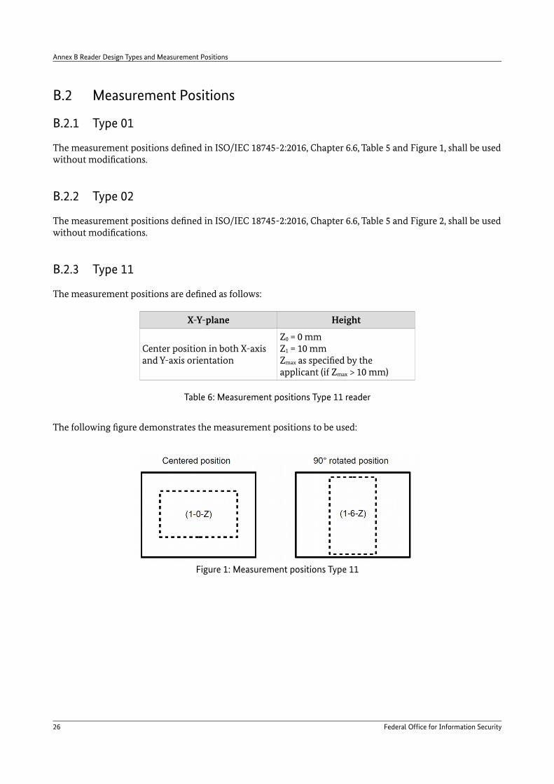
B.2.3 Type 11
The measurement positions are defined as follows:
X-Y-plane Height
Center position in both X-axis and Y-axis orientation
Z0 = 0 mmZ1 = 10 mmZmax as specified by the applicant (if Zmax > 10 mm)
Table 6: Measurement positions Type 11 reader
The following figure demonstrates the measurement positions to be used:
26 Federal Office for Information Security
Figure 1: Measurement positions Type 11

Reader Design Types and Measurement Positions Annex B
B.2.4 Type 12
As only a single card position is defined for a Type 12 reader (which has to be clearly marked on the device), this position shall also be the only measurement position.
B.2.5 Type MO
All tests with a Type MO reader are performed at a single measurement position which is to be defined by the applicant (in contrast to Type 12 readers, it is not required to clearly indicate the desired position on the device itself – an unambiguous description is considered sufficient).
Federal Office for Information Security 27

Reference Documentation
Reference Documentation
[1] ISO/IECISO/IEC 14443-1:2016Identification cards – Contactless integrated circuit cards – Proximity cards –Part 1: Physical characteristicsThird edition, 2016-03-15
[2] ISO/IECISO/IEC 14443-2:2016Identification cards – Contactless integrated circuit cards – Proximity cards –Part 2: Radio frequency power and signal interfaceThird edition, 2016-07-15
[3] ISO/IECISO/IEC 14443-3:2016Identification cards – Contactless integrated circuit cards – Proximity cards –Part 3: Initialization and anticollisionThird edition, 2016-06-01
[4] ISO/IECISO/IEC 14443-4:2016Identification cards – Contactless integrated circuit cards – Proximity cards –Part 4: Transmission protocolThird edition, 2016-06-01
[5] ISO/IECISO/IEC 10373-6:2016Identification cards – Test methods –Part 6: Proximity cardsThird edition, 2016-07-15
[6] ISO/IECISO/IEC 18745-2:2016Test methods for machine readable travel documents (MRTD) and associated readers –Part 2: Test methods for the contactless interface2016-08-15
[7] ISO/IECISO/IEC 7816-4:2013Identification cards – Integrated circuit cards –Part 4: Organization, security and commands for interchangeThird edition, 2013-04-15
[9] ICAODocument 9303Machine Readable Travel DocumentsParts 1 .. 12Seventh edition, 2015
28 Federal Office for Information Security

Keywords and Abbreviations
Keywords and Abbreviations
AA Active Authentication
ATQA Answer to request, type A
ATQB Answer to request, type B
ATS Answer To Select
BAC Basic Access Control
CID Card Identifier
DUT Device Under Test
EAC Extended Access Control
EGT Extra Guard Time
EMD Electromagnetic disturbance
EOF End Of Frame
ESD Electrostatic discharge
etu Elementary time unit
fc Carrier frequency (13.56 MHz)
FDT Frame delay time
fs Subcarrier frequency (847.5 kHz)
Hmax Maximum operating field strength
Hmin Minimum operating field strength
ICS Implementation Conformance Statement
m Modulation index
MRTD Machine Readable Travel Document
NAD Node address
PACE Password Authenticated Connection Establishment
PCD Proximity Coupling Device
PICC Proximity Integrated Circuit Card
PPS Protocol and Parameter Selection
RATS Request for Answer To Select
REQA Request command, type A
REQB Request command, type B
RF Radio frequency
RT Room temperature
SAC Supplemental Access Control
SCIC Secure Contactless Integrated Circuit
SOF Start Of Frame
Federal Office for Information Security 29

Keywords and Abbreviations
tr, tf Rise time, fall time
TR0 Guard time between the end of a PCD transmission and the start of the SCIC subcarrier generation
TR1 Synchronization time between the start of the SCIC subcarrier generation and the start of the SCIC subcarrier modulation
TR2 Synchronization time between the start of the SCIC’s EOF and the start of the PCD’s next SOF
30 Federal Office for Information Security


