36
PRODUCTS & SOLUTIONS BSR Series IE2-IE3-IE4 Synchronous Reluctance Motors

PRODUCTS &SOLUTIONS
BSR SeriesIE2-IE3-IE4
Synchronous Reluctance Motors


3
4 BSR series
5 BSR power drive system
6 Standard and directives
7 Efficiency classes and test method
8 Symbols and units of measure
9 Terms and definitions
10 The synchronous reluctance drive system
12 Selecting the BSR motor
14 Selecting Active Cube 410 for BSR motor
15 Rating plate
16 BSR Series designation
18 Technical data
19 Torque-speed characteristic
20 Dimensional tolerances
20 Bearings
21 Shaft loads
22 Flange versions
22 Ventilation
23 Degree of protection
24 Insulation class
24 Thermal protection
25 Mounting positions
26 Anti-condensation heaters
26 Second shaft extension
27 External mechanical protection
27 Terminal box
28 Dimensions
31 The BSR gearmotor package
32 Power drive system energy efficiency
34 Bonfiglioli Worldwide Presence
Index

4
The synchronous reluctance motor is an electric motor that combines a conventional three phase induction motor stator with an innovative rotor design.
The rotor is designed with a magnetic anisotropy resulting in the reluctance principle for the electromagnetic energy conversion without using
permanent magnets or rotor windings. The rotor design with the lamination holes yields a lower inertia and better dynamics in comparison with
an induction motor of the same size.
The reduction of rotor losses allows an increase of motor ratings in comparison with an induction motor in terms of both efficiency and power
density. Taking the advantage of this essential feature, Bonfiglioli is able to offer two distinctive versions in BSR synchronous reluctance motor series.
The High Efficiency (E) version is characterized by the Super Premium IE4 Efficiency Class level at all the rated operating points, including those in the
partial load range. The High Output (O) version allows to reduce the motor size in comparison with an induction motor of the same output power,
maintaining an efficiency level equal or higher than the IE2 Efficiency Class. When compared to high efficiency induction motors, the dynamic
performances are significantly higher, thanks to the lower rotor inertia.
Key benefits
• Efficient and Reliable:
- Competitive advantages in terms of Total Cost of Ownership
- Highest energy efficiency system IES2 and environmentally friendly solution
- High levels of reliability due to our production quality processes and internal know-how
• Dedicated to your application:
- BSR motors are designed to replace induction motors in variable speed applications, ensuring:
> Energy efficiency increase up to class IE4 if compared with induction motors
> A reduction of the motor frame up to two sizes with the same power of an induction motor
- BSR motors, in combination with Active Cube (ACU) 410, provide accurate speed, torque control
- Suitable for any variable speed applications, whether quadratic or constant torque
Typical applications are: pumps, fans, compressors, conveyors and winding machines
• Wide power range:
- 0.37…18.5 kW
• Accurate sensorless speed control:
- BSR in combination with Active Cube 410 provides excellent motor control without encoder feedbacks
Key features
• High energy efficiency of the motor up to class IE4 that lead to a remarkable energy saving.
• Extremely high efficiency from the partial load range up to the rated operating point
• Higher torque density in comparison with an induction motor of the same size
• High dynamic response through optimized control and low intrinsic moment of inertia
• High reliability and longer bearings life thanks to lower operating temperature
• High overload capability: Up to 300% of rated torque
• Effective torque and speed control (also at low speed) without encoder
• Perfect for retrofit thanks to IEC mechanical dimensions
• Optimized compatibility with Active Cube 410 drive series.
Areas of application:
BSR series • Synchronous Reluctance motor Economically and environmentally sustainable innovation
Illustration of the section of a Bonfiglioli synchronous reluctance motor BSR (left) in comparison with the one of an induction motor (right).
FOOD & BEVERAGE
PACKAGINGMATERIALHANDLING
TEXTILE
5
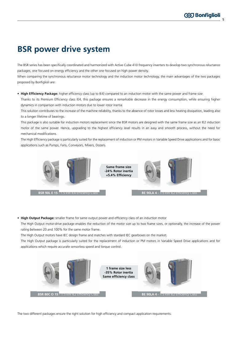
The BSR series has been specifically coordinated and harmonized with Active Cube 410 frequency inverters to develop two synchronous reluctance
packages, one focused on energy efficiency and the other one focused on high power density.
When comparing the synchronous reluctance motor technology and the induction motor technology, the main advantages of the two packages
proposed by Bonfiglioli are:
• High Efficiency Package: higher efficiency class (up to IE4) compared to an induction motor with the same power and frame size
Thanks to its Premium Efficiency class IE4, this package ensures a remarkable decrease in the energy consumption, while ensuring higher
dynamics in comparison with induction motors due to lower rotor inertia.
This solution contributes to the increase of the machine reliability, thanks to the absence of rotor losses and less heating dissipation, leading also
to a longer lifetime of bearings.
This package is also suitable for induction motors replacement since the BSR motors are designed with the same frame size as an IE2 induction
motor of the same power. Hence, upgrading to the highest efficiency level results in an easy and smooth process, without the need for
mechanical modifications.
The High Efficiency package is particularly suited for the replacement of induction or PM motors in Variable Speed Drive applications and for basic
applications such as Pumps, Fans, Conveyors, Mixers, Dozers.
• High Output Package: smaller frame for same output power and efficiency class of an induction motor
The High Output motor-drive package enables the reduction of the motor size up to two frame sizes, or optionally, the increase of the power
rating between 20 and 100% for the same motor frame.
The High Output motors have IEC design frame and matches with stardard IEC gearboxes on the market.
The High Output package is particularly suited for the replacement of induction or PM motors in Variable Speed Drive applications and for
applications which require accurate sensorless speed and torque control.
The two different packages ensure the right solution for high efficiency and compact application requirements.
BSR power drive system
BSR 80C O 15 - 1.5 kW IE2 Efficiency Class BE 90LA 4 - 1.5 kW IE2 Efficiency Class
1 frame size less-35% Rotor inertia
Same efficiency class
BSR 90L E 15 - 1.5 kW IE4 Efficiency Class BE 90LA 4 - 1.5 kW IE2 Efficiency Class
Same frame size-24% Rotor inertia+5.4% Efficiency

6
BSR motors are manufactured in accordance with applicable Standards and Directive listed on this page.
Standard and directives
BSR motors meet the requirements of Directives 2006/95/EC (Low Voltage Directive CE mark is applied to this product).
Directives
STANDARD TITLE STANDARD TITLE
General requirements for rotating electrical machines IEC 60034-1
Terminal marking and direction of rotation of rotating machines IEC 60034-8
Methods of cooling for electrical machines IEC 60034-6
Dimensions and output ratings for rotating electrical machines IEC 60072
Classification of degree of protection provided by enclosures for rotating machines IEC 60034-5
Noise limits IEC 60034-9
Classification of type of constructing and mounting arrangements IEC 60034-7
Vibration level of electric machines IEC 60034-14
Efficiency classes of variable speed AC motors (IE code) IEC TS 60034-30-2
Specific test methods for determining losses and efficiency of converter-fed AC motor IEC 60034-2-3
Standard
7
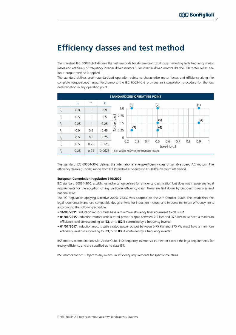
The standard IEC 60034-2-3 defines the test methods for determining total losses including high frequency motor
losses and efficiency of frequency inverter driven motors(1). For inverter driven motors like the BSR motor series, the
input-output method is applied.
The standard defines seven standardized operation points to characterize motor losses and efficiency along the
complete torque-speed range. Furthermore, the IEC 60034-2-3 provides an interpolation procedure for the loss
determination in any operating point.
The standard IEC 60034-30-2 defines the international energy-efficiency class of variable speed AC motors. The
efficiency classes (IE code) range from IE1 (Standard efficiency) to IE5 (Ultra Premium efficiency).
European Commission regulation 640/2009
IEC standard 60034-30-2 establishes technical guidelines for efficiency classification but does not impose any legal
requirements for the adoption of any particular efficiency class. These are laid down by European Directives and
national laws.
The EC Regulation applying Directive 2009/125/EC was adopted on the 21st October 2009. This establishes the
legal requirements and eco-compatible design criteria for induction motors, and imposes minimum efficiency limits
according to the following schedule:
• 16/06/2011: Induction motors must have a minimum efficiency level equivalent to class IE2
• 01/01/2015: Induction motors with a rated power output between 7.5 kW and 375 kW must have a minimum
efficiency level corresponding to IE3, or to IE2 if controlled by a frequency inverter
• 01/01/2017: Induction motors with a rated power output between 0.75 kW and 375 kW must have a minimum
efficiency level corresponding to IE3, or to IE2 if controlled by a frequency inverter
BSR motors in combination with Active Cube 410 frequency inverter series meet or exceed the legal requirements for
energy efficiency and are classified up to class IE4.
BSR motors are not subject to any minimum efficiency requirements for specific countries.
Efficiency classes and test method
STANDARDIZED OPERATING POINT
n T P
p.u. values refer to the nominal values
P1
0.9 1 0.9
P2
0.5 1 0.5
P3
0.25 1 0.25
P4
0.9 0.5 0.45
P5
0.5 0.5 0.25
P6
0.5 0.25 0.125
P7
0.25 0.25 0.0625
Torq
ue [p
.u.]
Speed [p.u.]
00.2 0.3 0.4 0.5 0.6 0.7 0.8 0.9 1
0.5
0.25
0.75
1.0(3)
(7)
(2)
(5)
(6)
(4)
(1)
(1) IEC 60034-2-3 uses “converter” as a term for frequency inverters.

8
Symbols and units of measure
SYMBOL U.M. DESCRIPTION
η4/4
[-] Efficiency at Pn
fH
[-] Altitude adjustment factor
fn
[Hz] Rated frequency
fT
[-] Temperature adjustment factor
In
[A] Rated current
Iol
[A] Overload current
Ip
[A] Peak current
Jm
[kgm2 x10-4] Motor moment of inertia
mIM B5
[kg] Mass with IM B5 mounting
MEQU
[Nm] Equivalent torque
Mn
[Nm] Rated torque
Mol
[Nm] Overload torque at nn
Mp
[Nm] Peak torque
nn
[min-1] Rated speed
nmax
[min-1] Maximum speed
Pn
[kW] Rated power
Unless otherwise specified, all dimensions are expressed in millimeters.

9
Duty type S1: Operation at constant load maintained for sufficient time to allow the machine to reach thermal equilibrium.
Duty type S3: sequence of identical duty cycles, each including a time of operation at constant load and a time de-energized and at rest. If not specified the cycle time is fixed equal to 10 minutes.
Electric time constant [τel]: is the time taken for the current to reach 63.2% of its steady state value when a step input voltage is applied while the rotor is stationary. It is calculated by dividing the winding phase-to-phase inductance (L
pp) by the winding phase-to-phase resistance (R
pp) at 20°C.
Terms and definitions
τel
= Lpp
/ Rpp
tf Work time under constant load
tr Rest time
Intermittence:
I = ∙ 100
tf
tf + t
r
P[kW]
t[°C]
tc
tf tr
t
Rated speed [nn]: is the speed at which the motor has been designed to operate with a reasonable level of control, in terms of overload torque (M
ol) and overspeed.
Rated torque [Mn]: is the thermally permissible continuous torque for S1 duty at the rated motor speed (nn).
Thermal equilibrium: is the state reached when the temperature rise of the several parts of the machine do not vary by more than a gradient of 2 K per hour.
Thermal time constant [τtherm]: is the time for the temperature to reach 63.2% of this final value between the motor housing and the ambient after a step-wise current change.
Winding temperature rise [dT]: is the temperature rise, in specified service conditions, of the motor windings above the maximum ambient reference temperature.
Rated power [Pn]: is the mechanical power available at shaft at rated speed nn.
Peak current [Ip]: is the current used to produce the peak torque (Mp). It is the current limit of the machine, and if
exceeded, even for a short period, an irreversible damage to the machine can occur.
Peak torque [Mp]: is the absolute maximum torque that can be produced by a motor for a short time.
Rated current [In]: is the RMS current to produce the rated torque (Mn).
Overload current [Iol]: is the RMS current to produce the overload torque (Mol) at rated speed (n
n).
Overload torque [Mol]: is the overload torque at rated speed (nn).
Rated frequency [fn]: is the frequency of the fundamental component of the output voltage corresponding at the rated speed (n
n) according to the following equation where p is the pole pairs.
fn = p ∙ n
n / 60
Pn = 2π ∙ M
n ∙ n
n / 60

10
The synchronous reluctance drive systemSmart motor control for your application
FLEXIBLE CONTROL STRATEGIES
ParameterIdentification
StartingOptions
Rotor Position Control
FluxControl
Optimized control for best PERFORMANCE and EFFICIENCY
Nom.Speed & Const. Torque
Range
High Speed & Const. Power
Range
Start with Current Injection
Start with Sensorless
Field Oriented Control
SensorlessStart with Feedback#
SensorBased#
Improved Efficiency
with MTPA Table
Operation at Voltage Limit
Standard Option for
Acceleration Ramps
At fast Acceleration
Ramps
Fundamental Model with Impedance
Map
If implemented
Beneficial at very low
Speed
The BSR motors are optimized for operating with Active Cube 410 inverter series. Thanks to the motor data
integration in the inverter software VPlus, the set up is extremely fast and easy.
The resulting power drive system meets all the requirements for the IES2 top efficiency classification.
Active Cube 410 Series
Power range:
from 0.25 kW to 400 kW
Overload capacity
• up to 150% for 60 seconds
• up to 200% for 1 second
Motor Control (open loop or optional closed loop):
• Asynchronous AC motors
• Synchronous reluctance motors
• Permanent magnet synchronous (brushless) motors
Communication modules
• Different field bus options like CANopen, PROFIBUS, Modbus, EtherCAT, PROFINET, Varan
• Optional I/O extensions for addtional digital and analogue inputs & outputs
# on request

11
The synchronous reluctance drive system guarantees excellent control performance thanks to optimized, model-
based sensorless control.
The dedicated Active Cube 410 motor control allows to operate the BSR motor with these features and benefits:
• Exploit the maximum peak torque and dynamic thanks to a precise flux control,
• Maximize the motor efficiency even at partial load thanks to the implemented motor model,
• Take advantage of the field weakening control at high speed.
The synchronous reluctance drive systemIncrease your machine productivity
Flux Control Benefits: Extracting Maximum Torque
Capability• Efficiency Optimisation• Field Weakening
Comprehensive Control Structurefor Flexible Adaption to Countless Applications
Field Oriented Sensorless Control:• Precise control with accurate machine model• Achieving Dynamics with Advanced Motor Model
Start-Up Manager:• Nominal Torque available at f = 0 Hz• Various Options for any Application
Speed Reference
Ref. Flux
Est. Flux
Est.Speed
i
id
i*
u*
iq
u*
FieldWeakening
Nominal SpeedRange
FieldController
SpeedController
CurrentController
Start-Up Manager• Current Injection• Field Oriented Start• Start with motor feedback#
Advanced Motor Model
Impedance Map
Voltage LimitOperation
Optimized FluxTable
FluxEstimation
AngleEstimation
Sensorless Reluctance Motor Control with Active Cube 410
# on customer request

12
Selecting the BSR motor
0
M(1)
n(2)
Load diagram [Nm]
Speed diagram [min-1]
M(3)
M(2)
t1 t2 t3 t4
Time [s]
(a) Equivalent torque MEQU
[Nm]M2
(1) · t
1 + M2
(2) · t
2 + ... + M2
(n) · t
n
t1 + t
2 + ... + t
n
=MEQU
(b) Temperature adjusting factor fT
-fT
Ambient temperature [°C]
1.3
1.2
1.1
1
0.9
0.8-20 0 20 40 60
(c) Altitude adjustment factor fH
-fH
Altitude meters above sea level
1
0.9
0.8
0.7
0.60 1000 2000 3000
(d) Equivalent current IEQU
[A]M2
(1) · t
1 + M2
(2) · t
2 + ... + M2
(n) · t
n
t1 + t
2 + ... + t
n
=IEQU

13
Selecting the BSR motor
Select a bigger motor size
NO
NO
NO
START
END
Select the required motor version:
E - High efficiency
O - High output
From load cycle determine:
Maximum torque and relative speed
Maximum speed and relative torque
Select motor size, power rating and nominal speed
Select a bigger motor size
Select a bigger motor size
Calculate equivalent torque
Calculate fT
Calculate fH
YES
YES
YES
Are all working points ofthe load cycle below the
motor limit curve?
Mn * f
T* f
H > M
EQU
Does the motorinertia match the load
inertia?
(a)
(b)
(c)

14
Selecting Active Cube 410 for BSR motor
Select a bigger inverter size
NO
END
YES
Is ACU410 selection fitting according to derating
figures?
Start Simplified Selection ACU410
Determine from load cycle:
Mmax
& tmax current
: Maximum torque & corresponding time
MEQU
: Equivalent torque
Select inverter based on Imax
, tmax current
and IEQU
Consider a 10 % current reserve when selecting the
inverter
Determine derating figures according to ACU410
operating instructions*:
Temperature, Altitude, Voltage, Switching Frequency
Determine from motor selection and load cycle:
Determine kT= M
N/I
N
Imax
: Maximum current IMAX
= MMAX
/kT
IEQU
: Equivalent current IEQU
= MEQU
/kT
*: Derating has to be considered in these cases:
More than 40°C
More than 1000 m altitude
More than 3~ 400 V mains supply
PWM switching frequency 8 kHz or higher

15
In accordance with IEC 60034-1, the motor rating plate summarizes the motor rating including the total weight.
Example of rating plate and field’s description are reported hereafter.
Fields:
1) Product designation
2) Product code
3) Serial number
4) Insulation class
5) Nominal power
6) Total weight
7) Degree of protection
8) Motor mounting
9) Duty cycle
10) Nominal frequency
11) Nominal voltage and winding connection
12) Nominal current
13) Nominal efficiency at full load
14) Nominal speed
15) Maximum speed
16) Maximum ambient temperature
17) Option data (e.g. fan unit data)
18) Efficiency class (IE code)
19) Drive end bearing type
20) Non drive end bearing type
21) Serial number as barcode
Rating plate
Example of BSR rating plate:
Cod. No. CLkW kg IP IM S
Ambnom max max
Y
DENDE
Made in Italy - Bonfiglioli Mechatronic Research S.p.a.
IEC - EN600034
3~ Mot.
INVERTER DUTY ONLY
1
min-1Hz V A %
EFFICIENCY CLASS
2 3 4
5 6 7 8 9
10 11 12 13 14 15 16
18
19
20 21
17

16
MOTOR
BSR Series designation
Degree of protection55 IP 55(2)
56 IP 56
Nominal line voltage40 400V (Y connection)
Motor ratingE High Efficiency(1)
O High Output
Nominal speed15 1500 min-1
30 3000 min-1
Motor typeBSR IEC 3-Phase Synchronous Reluctance Motor
Insulation classF Class F(2)
H Class H
BSR 40 FE80B 5515
Motor size71B … 132MB (IEC Motor)

17
OPTIONS
Thermal protective devicesK1(5) Silicon sensor type KTY 84-130E3 Thermistor PTCP1 Platinium sensor PT1000
Forced ventilationU1(6) Power supply 1~230V (71-100), 3~400V Y (112-132)
Anti-condensate heatersH1 Power supply 1~230V
Double-extended shaftPS(6)
External mechanical protectionTC(6)
Rotor balancing grade BRV
...
Motor mountingB3 IM B3, IM B6, IM B7, IM B8, IM V5, IM V6B5 IM B5, IM V1, IM V3B14 IM B14, IM V18, IM V19B5R IM B5 not standardized(3)
B14R IM B14 not standardized(4)
B5
Notes:(1) Not available with nominal speed 3000min-1
(2) Default value(3) Flange with through holes with reduced coupling dimensions (4) Flange with tapped holes with reduced coupling dimensions. Not available for motor size 112 and 132 (5) Not compatible with insulation class H (6) Options U1, PS and TC are mutually exclusive

18
Operation with ACU410 frequency inverter series - rated voltage 400V - 1.5xMn overload at nominal speed (Mol) - 3xMn Peak overload (Mp)
4-pole 50 Hz 1500rpm Y Connection
Pn Size - Rating - Speed η4/4 IE Mn In Iol Ip nmax Jm mIM B5
Suggested ACU410 inverter with150% overload for max. 60 s
High Efficiency (E) - S1 duty cycle
kW % Code Nm A A A min-1 kgm2 x10-4 kg
0,37 BSR 71B E 15 81,5 IE4 2,4 1,1 1,5 2,9 2250 8 5,7 ACU 410 03 1 F…
0,55 BSR 71C E 15 83,9 IE4 3,5 1,6 2,2 4,1 2250 10 7,1 ACU 410 03 1 F…
0,55 BSR 80B E 15 83,9 IE4 3,5 1,6 2,2 3,6 2250 17 9,5 ACU 410 03 1 F…
0,75 BSR 80C E 15 87,0 IE4 4,8 2,2 2,9 5,1 2250 22 12,2 ACU 410 07 1 F…
1,1 BSR 90S E 15 88,3 IE4 7,0 3,0 3,9 7,0 2250 22 13,1 ACU 410 09 1 F…
1,5 BSR 90L E 15 88,2 IE4 9,5 4,0 5,5 9,5 2250 26 14,5 ACU 410 12 2 F…
2,2 BSR 100LA E 15 89,5 IE4 14,0 5,8 8,0 14,3 2250 45 22 ACU 410 13 2 F…
3 BSR 100LB E 15 90,4 IE4 19,1 7,8 11,3 19,8 2250 50 24 ACU 410 15 2 F…
4 BSR 112M E 15 91,1 IE4 25 9,7 13,5 24,7 2250 82 31 ACU 410 19 3…
5,5 BSR 132S E 15 92,1 IE4 35 13,5 18,8 36 2250 220 51 ACU 410 19 3…
7,5 BSR 132MA E 15 92,7 IE4 48 17,8 25,5 52 2250 255 57 ACU 410 21 3…
9,2 BSR 132MB E 15 93,0 IE4 59 21,6 32 64 2250 280 67 ACU 410 22 3…
High Output (O) - S1 duty cylce
kW % Code Nm A A A min-1 kgm2 x10-4 kg
0,55 BSR 71B O 15 80,8 IE3 3,5 1,7 2,4 4,4 2250 8 5,7 ACU 410 05 1 F…
0,75 BSR 71C O 15 82,5 IE3 4,8 2,1 3,4 6,2 2250 10 7,1 ACU 410 07 1 F…
0,75 BSR 80A O 15 79,6 IE2 4,8 2,1 3,5 5,9 2250 13 8,0 ACU 410 07 1 F…
1,1 BSR 80B O 15 81,4 IE2 7,0 3,1 4,5 9,5 2250 17 9,5 ACU 410 09 1 F…
1,5 BSR 80C O 15 82,8 IE2 9,5 3,9 6,9 10,9 2250 22 12,2 ACU 410 12 2 F…
2,2 BSR 90S O 15 85,9 IE2 14,0 5,6 8,2 16,8 2250 22 13,1 ACU 410 13 2 F…
3 BSR 90L O 15 85,5 IE2 19,1 7,6 11,7 24,0 2250 26 14,5 ACU 410 15 2 F…
4 BSR 100LB O 15 88,6 IE3 25 10,5 15,3 30 2250 50 24 ACU 410 19 3…
5,5 BSR 112M O 15 89,6 IE3 35 13,5 19,5 42 2250 82 31 ACU 410 19 3…
7,5 BSR 132S O 15 91,3 IE3 48 18,4 25,3 52 2250 220 51 ACU 410 22 3…
9,2 BSR 132MA O 15 91,6 IE3 59 22,0 33 66 2250 255 57 ACU 410 23 3…
11 BSR 132MB O 15 91,5 IE3 70 24,7 32 77 2250 280 67 ACU 410 23 3…
Operation with ACU410 frequency inverter series - rated voltage 400V - 1.5xMn overload at nominal speed (Mol) - 3xMn Peak overload (Mp)
4-pole 100 Hz 3000rpm Y Connection
High Output (O) - S1 duty cylce
kW % Code Nm A A A min-1 kgm2 x10-4 kg
1,1 BSR 71B O 30 85,2 IE4 3,5 3,1 4,5 8,5 4500 8 5,7 ACU 410 09 1 F…
1,5 BSR 71C O 30 87,1 IE4 4,8 4,2 6,2 11,7 4500 10 7,1 ACU 410 12 2 F…
1,5 BSR 80A O 30 84,7 IE3 4,8 4,1 5,9 11,2 4500 13 8,0 ACU 410 12 2 F…
2,2 BSR 80B O 30 86,3 IE3 7,0 5,8 8,5 16,0 4500 17 9,5 ACU 410 13 2 F…
3 BSR 80C O 30 88,3 IE3 9,5 7,8 11,6 19,7 4500 22 12,2 ACU 410 15 2 F…
4 BSR 90S O 30 90,2 IE3 12,7 9,9 15,2 27,3 4500 22 13,1 ACU 410 19 3…
5,5 BSR 90L O 30 90,9 IE4 17,5 13,5 20,6 43 4500 26 14,5 ACU 410 19 3…
7,5 BSR 100LB O 30 91,7 IE4 24 20,0 27,8 56 4500 50 24 ACU 410 22 3…
11 BSR 112M O 30 91,9 IE3 35 24,5 36 77 4500 82 31 ACU 410 23 3…
15 BSR 132S O 30 92,0 IE3 48 36 53 107 4500 220 51 ACU 410 27 3…
18,5 BSR 132MA O 30 92,4 IE3 59 43 62 126 4500 255 57 ACU 410 29 3…
Technical data

19
The permissible operating range of a Synchronous Reluctance motor is defined by thermal, mechanical and sensorless control limit.
The behavior of the BSR synchronous reluctance motor is described by a torque-speed operating area obtained by the combination of the BSR motor series and the Active Cube 410 frequency inverter series. Exceeding the nominal speed the continuous torque curve decreases according to the constant power limit. The continuous duty zone is limited by the maximum continuous torque curve and the voltage limit curve. Continuous duty in the area above the S1 curve is not permitted. The intermittent periodic duty zone is limited by the peak torque line and the voltage limit curve.
The significant working points used to define the operation zone of the BSR motors are highlighted in the graph
above and the following table. The values refer to rated torque (Mn) and rated speed (n
n) as “per unit (p.u.)”
expression,
(1) The value is valid only for BSR motor with nominal speed 1500 min-1
(2) The value is valid only for BSR motor with nominal speed 3000 min-1
Torque-speed characteristic
Voltage limit
Torq
ue [N
m]
Speed [min-1] nn
nmax
Mp
Mol
Mn
Intermittent Duty
Continuous Duty
BSR ... E
BSR ...
O
1
4
2
5
3
6
7
SYMBOL U.M. DESCRIPTION
1 2 3 4 5 6 7
Torque [p.u.] 0.4 1 0.4 1.5 3 3 1.5
Speed [p.u.] 0 0.4(1) 0.2(2) 1.5 0 0.3 0.8 1
Duty - Continuous Intermittent

20
Dimensions and tolerances of shaft end, key and flange are in accordance with IEC 60072-1. Shaft ends feature an
axial threaded hole in accordance with UNI 3221, DIN 332 and a key inserted in the suitable keyway. The following
table reports the tolerances for the different parts:
Dimensional tolerances
COUPLING DIMENSION DIMENSIONS RANGE TOLERANCE
Shaft end D - DAØ 11-28 j6
Ø 38-48 k6
Key F - FA - h9
Flange N Ø < 250 j6
BSR motors use radial ball bearings, lubricated for life with grease and axially pre-loaded. The type of bearings in use
are listed in the following table.
(1) Only for the B5R motor mounting variant.
Bearings
SIZE PROTECTION DEGREE IP55 PROTECTION DEGREE IP56
DRIVE END NON DRIVE END DRIVE END NON DRIVE END
BSR 71 6202 2Z C3 6203 2Z C3(1) 6202 2Z C3 6202 2RS C3 6203 2RS C3(1) 6202 2RS C3
BSR 80 6204 2Z C3 6204 2Z C3 6204 2RS C3 6204 2RS C3
BSR 90 6205 2Z C3 6205 2Z C3 6205 2RS C3 6205 2RS C3
BSR 100 6206 2Z C3 6207 2Z C3(1) 6206 2Z C3 6206 2RS C3 6207 2RS C3(1) 6206 2RS C3
BSR 112 6306 2Z C3 6306 2Z C3 6306 2RS C3 6306 2RS C3
BSR 132 6308 2Z C3 6308 2Z C3 6308 2RS C3 6308 2RS C3

21
The maxium radial load (FR) and maximum axial load (F
A) are computed using ISO 281 calculation L
10h assuming a
bearing life of 20.000h. The load and the speed are assumed to be constant throughout the bearing life.
The maximum radial load is reported as a function of the distance (X) between flange plane and the point of force
applicaton. The maximum radial loads FR are valid only for the horizontal installation of the motor without additional
axial load.
Shaft loads
FA
FR
x
X [mm]0 10 20 30
FR
[N
]
600
650
700
750
800
850
900
950BSR 71B-71C
1500 min-1
3000 min-1
X [mm]0 20 40 60
FR
[N
]
900
1000
1100
1200
1300
1400
1500BSR 100LA-100LB
1500 min-1
3000 min-1
X [mm]0 20 40
FR
[N
]
500
550
600
650
700
750
800
850
900
950
1000BSR 80A-80B-80C
1500 min-1
3000 min-1
X [mm]0 20 40 60
FR
[N
]
1300
1400
1500
1600
1700
1800
1900
2000
2100BSR 112M
1500 min-1
3000 min-1
X [mm]0 20 40
FR
[N
]
650
700
750
800
850
900
950
1000
1050BSR 90S-90L
1500 min-1
3000 min-1
X [mm]0 20 40 60 80
FR
[N
]
2000
2200
2400
2600
2800
3000
BSR 132S-132MA-132MB
1500 min-1
3000 min-1

22
Flange output motors are available with reduced coupling dimensions corresponding to product variants B5R (with
through holes) and B14R (with tapped holes). Dimensions are indicated in the table below:
Flange versions
The standard BSR motor is equipped with a self-cooling fan (IC 411 in accordance with CEI EN 60034-6). The fan and
the resulting cooling is optimized for rated speed. Installation must take into account a minimum distance of the fan
cover from the nearest wall to ensure unobstructed air circulation.
For machines operating frequently or for long periods of time at small speeds the BSR motor can be equipped with
the optional fan unit U1 (referred to as IC 416 in standard CEI EN60034-6). The terminals of the U1 fan unit are
housed in a separate terminal box.
The following table summarizes the electrical data of the fan unit U1 and the increase of motor length.
(1) Dimension variation compared to length LB of the corresponding standard motor.
Ventilation
MOTOR SIZE ELECTRICAL DATA OF FAN UNIT U1 ΔLB(1)
VAC ±10% Hz P [W] I [A] [mm]
BSR 71
1 ~ 230
50/60
22 0.12 93
BSR 80 22 0.12 127
BSR 90 40 0.30 131
BSR 100 50 0.25 119
BSR 1123 ~ 230 Δ / 400 Y
50 0.26 / 0.15 130
BSR 132 110 0.38 / 0.22 161
SIZE D E M N P
BSR 71B5R 11 23 115 95 140
B14R 11 23 75 60 90
BSR 80B5R 14 30 130 110 160
B14R 14 30 85 70 105
BSR 90 B5R 19 40 165 130 200
B14R 19 40 100 80 120
BSR 100B5R 24 50 165 130 200
B14R 24 50 115 95 140
BSR 112 B5R 24 50 165 130 200
BSR 132 B5R 28 60 215 180 250
E
DP

23
IP55 is used as default protection class for the BSR motor configuration. Optionally the protection class IP56 is
available as variant, please check the product designation.
In accordance with IEC 60034-5:
Degree of protection
0 0
1 1
2 2
3 3
4 4
5 5
6 6
7
8
∅ 50 mm
∅ 12 mm
∅ 2,5 mm
∅ 1 mm
IP 5 5
Not protected
Protected against extraneous solid bodies having Ø ≥ 50 mm
Protected against extraneous solid bodies having Ø ≥ 12.5 mm
Protected against extraneous solid bodies having Ø ≥ 2.5 mm
Protected against extraneous solid bodies having Ø ≥ 1.0 mm
No dust ingress
Protected against dust
Not protected
Protected against vertical water drips
Protected against vertical water drips inclined up to 15°
Protected against rain
Protected against water splashes
Protected against powerful jets of water
Protected against the effects of temporary immersion
Protected against the effects of continuous immersion
Protected against jets of water

24
BSR motors are designed according to class F insulating materials as standard variant. Optionally the insulation class H
is available for BSR motors.
For application involving the presence of aggressive chemicals or high humidity, please contact Bonfiglioli.
During the commissioning of the Active Cube 410 frequency inverter, the connected BSR motor is set up. During this setup
a software I²t monitoring is activated offering an inexpensive solution for thermal monitoring with the possibility to set up a
fault switch off inside the frequency inverter.
Optionally the BSR motor can be equipped with a hardware thermal switch that can be evaluated with the Active Cube 410.
A hardware monitoring is especially recommended for motors with forced ventilation (U1 option). The available thermal
switches are:
Insulation class
Thermal protection
F H
Hottest point margin with temperature determination by resistance method
Increase allowed bythe temperature
Max. ambienttemperature
OPTION THERMAL SWITCH DESCRIPTION
K1 Type KTY 84-130
A KTY silicon semi-conductor resistance sensor is placed in contact with the motor winding. The working temperature range is from 0°C to 170°C. This sensor cannot be used in combination with insulation class H.
E3 PTC
3 PTC thermistors are placed in contact with the motor winding. The thermistor switch temperature is in accordance with the insulation class of the motor. For the PTC thermistor resistance curve please refer to the Standard DIN 44081-82.
P1 PT1000
A platinum resistance temperature sensor is placed in contact with the motor winding. The PT1000 characteristic is in accordance with IEC 60751 : 2008, tolerance class B. The working temperature is from -40°C to 250°C.

25
EC-normalised BSR motors are available in the design versions as indicated in the following table according to
Standards EN 60034-7.
BSR is available with the following mounting versions:
IM B3 (basic)
IM B6, IM B7, IM B8, IM V5, IM V6 (derived)
IM B5 (basic)
IM V1, IM V3 (derived)
IM B14 (basic)
IM V18, IM V19 (derived)
IM B3 design motors can be installed in positions IM B6, IM B7, IM B8, IM V5 and IM V63; IM B5 design motors can
be installed in positions IM V1 and IM V3; IM B14 design motors can be installed in positions IM V18 and IM V19.
In such cases, the basic design IM B5 or IM B14 is indicated on the motor name plate.
Mounting positions
IM B3 IM B6 IM B7
IM B5 IM V1 IM V3
IM B14 IM V18 IM V19
IM B8 IM V5 IM V6
26
Where an application involves high humidity or extreme temperature fluctuations, motors can be equippen optionally
with an anti-condensation heater (option H1). A single-phase power supply is available in the auxiliary terminal board
inside the main terminal box.
The following table summarizes the electrical properties of the anti-condensation heater.
Anti-condensation heaters
VOLTAGE POWER
[V] [W]
BSR 71 - BSR 801 ~ 230 ±10%
10
BSR 90 … BSR 132 25
Second shaft extension
A second shaft extension is available selecting the option PS. This option cannot be used in combination with options
U1 or TC. The shaft dimensions correspond to the first shaft and are summarized in the dimensions table in this
catalogue.
PS

27
Terminal board features 6 studs for eyelet terminal connections. A ground terminal is also supplied for hearting of the
equipment. Terminal number and dimension are shown in the following table. In motor design IM B3, the terminal
box is on the top (side opposite to feet).
The cable entries of the terminal boxes use metric threads in accordance with standard EN 50262 as indicated in
the following table.
Terminal box
BSR SIZENUMBERS OFTERMINALS
TERMINALTHREADS
WIRE CROSSSECTION AREA
[mm2]
BSR 71 … BSR 906
M4 2.5
BSR 100 … BSR132 M5 6
BSR SIZE CABLE GLAND AND DIMENSIONSMAXIMUM CABLE
DIAMETER ALLOWED
[mm]
BSR 71 2 x M25 x 1.51 Hole on each side
17
BSR 80 ... BSR 90 2 x M25 x 1.5 17
BSR 100 ... BSR 1122 x M32 x 1.52 x M25 x 1.5 2 Holes on each side
2117
BSR 132 4 x M32 x 1.5 21
In applications with high risk of obstructions of the fan (i.e. flying lints in textile industry environments) the option TC
(textile canopy) can be added as option.
The following table summarizes the dimensions per motor size.
AQ ΔV
BSR 71 134 27
BSR 80 152 25
BSR 90 168 30
BSR 100 190 28
BSR 112 211 32
BSR 132 254 32
External mechanical protection

28
Dimensions
LC
L
LBE EA
BCK
BB
LLV
D
DA
AC
DB
GC
FA
DB
GA
F
AF
A
AB
HA
HA
D
B3
SHAFT
D DA E EA DB GA GC F FA
BSR 71 14 30 M5 16 5
BSR 80 19 40 M6 21,5 6
BSR 90 24 50 M8 27
5BSR 10028 60 M10 31
BSR 112
BSR 132 38 80 M12 41 10
HOUSING B3
B A HA BB AB K C H
BSR 71 90 112 8 112 135 45 71
BSR 80100
125 8 124 153
10
50 80
BSR 90 S140 8 155 174 56 90
BSR 90 L 125
BSR 100140
16010 175
192
12
63 100
BSR 112 190 224 70 112
BSR 132 178 216 12 218 254 89 132
MOTOR
AC L LB LC AD AF LL V
BSR 71 138 249 219 281 10874 80
37
BSR 80 156 274 234 315 119 38
BSR 90 176 326 276 378 133
98 98
44
BSR 100 195 367 307 429 142 50
BSR 112 219 385 325 448 157 52
BSR 132 258 493 413 576 193 118 118 58
EA: Second shaft available as option

29
Dimensions
DB
GC
FADA
P DN
T
V LL
E LB EAL
LC
AC
LA
DB
GA
F
AF
45°
MS
AD
B5
SHAFT
D DA E EA DB GA GC F FA
BSR 71 14 30 M5 16 5
BSR 80 19 40 M6 21,5 6
BSR 90 24 50 M8 27
5BSR 10028 60 M10 31
BSR 112
BSR 132 38 80 M12 41 10
HOUSING B5
M N P S T LA
BSR 71 130 110 160 9.5
3.5
10
BSR 80165 130 200 11.5 11.5
BSR 90
BSR 100215 180 250
14 4
14
BSR 112 15
BSR 132 265 230 300 20
MOTOR
AC L LB LC AD AF LL V
BSR 71 138 249 219 281 10874 80
37
BSR 80 156 274 234 315 119 38
BSR 90 176 326 276 378 133
98 98
44
BSR 100 195 367 307 429 142 50
BSR 112 219 385 325 448 157 52
BSR 132 258 493 413 576 193 118 118 58
EA: Second shaft available as option

30
Dimensions
DB
GC
FADA
P N D
T
V LL
E LB EAL
LC
AC
DB
GA
F
AF
45°
M
S
AD
B14
SHAFT
D DA E EA DB GA GC F FA
BSR 71 14 30 M5 16 5
BSR 80 19 40 M6 21,5 6
BSR 90 24 50 M8 27
5BSR 10028 60 M10 31
BSR 112
BSR 132 38 80 M12 41 10
HOUSING B14
M N P S T
BSR 71 85 70 105M6
2.5
BSR 80 100 80 1203
BSR 90 115 95 140
M8BSR 100130 110 160 3,5
BSR 112
BSR 132 165 130 200 M10 4
MOTOR
AC L LB LC AD AF LL V
BSR 71 138 249 219 281 10874 80
37
BSR 80 156 274 234 315 119 38
BSR 90 176 326 276 378 133
98 98
44
BSR 100 195 367 307 429 142 50
BSR 112 219 385 325 448 157 52
BSR 132 258 493 413 576 193 118 118 58
EA: Second shaft available as option

31
Control, flexibility, efficiency and compactness are fundamental characteristics in a wide range of industrial processes
and applications.
To match these needs Bonfiglioli has developed a new solution, represented by the Bonfiglioli synchronous reluctance
motor (BSR), combined with the helical or worm technology of Bonfiglioli A, C, F, S and VF-W gear units.
The synergy between BSR motors and A, C, F, S and VF-W gearboxes allows to exploit the robustness and wide torque
range of Bonfiglioli industrial gear units, as well as the flexibility and efficiency of Bonfiglioli reluctance motors.
The BSR gearmotor package
CAF
VF, W
BSRSynchronous Reluctance Motor
Maximum Flexibility
Two different solutions available:
• High Efficiency Package: BSR in IE4 efficiency class combined with A, C, F, S gearboxes
• High Output Package: BSR in IE2, IE3, IE4 efficiency class combined with A, C, F, S and VF-W gearboxes
Modularity
The modular coupling between BSR and Bonfiglioli gearboxes guarantees extended customization capability. Indeed,
the full range of versions and options of the A, C, F, S and VF-W gearboxes, can be used to customize the solution
and perfectly match customers’ needs.
One stop shop
All the components of the drive package are manufactured by Bonfiglioli. This ensures the highest level of
performances and compatibility. At the same time our customers can rely on a unique supplier for all gearboxes,
motors and inverters.
Areas of Application
PACKAGING RORATYTABLE
ROTARYMACHINES
PICK & PLACE SOLUTIONS
MATERIALHANDLING

32
The international standard IEC61800-9 deals with the energy efficiency of complete drive modules (CDM) and power
drive systems (PDS). The standard IEC 61800-9 is harmonized in Europe as EN 61800-9 and replaces the earlier
standard EN 50598 (-1 and -2).
As represented in the following diagram, the power drive system consists of the complete drive module and the
electrical motor, including the motor cable. The standard defines the IE classes for CDM and the IES classes for PDS.
The IEC standard 61800-9-2 specifies the procedure for determining the losses of the PDS in 8 application-relevant
operating points for motor drive applications in the power range from 0.12 kW to 1,000 kW.
Losses of the reference power drive system (RPDS) are defined for the 8 specific operating points and the international
efficiency of systems classes (IES) for the PDS. The PDS energy efficiency is classified in the range of IES0 - IES2 as
described in the following illustration.
Illustration of the operating points (shaft speed, torque)
for the determination of the relative losses of the PDS
according to IEC 61800-9-2.
Illustration of the IES classes of a PDS
according to IEC 61800-9-2.
Power drive system energy efficiency
PDS
Electric powerfrom mains
Motor electricpower
Mechanical poweron shaft
CDM losses Motor losses
MainsSupply
CDM Motor Load
PDS
rela
tive
torq
ue (%
)
PDS relative speed (%)
50 100
50
25
100p
L, PDS (0; 100)
pL, PDS (0; 50)
pL, PDS (0; 25)
pL, PDS (50; 25)
pL, PDS (50; 100)
pL, PDS (50; 50)
pL, PDS (100; 100)
pL, PDS (100; 50)
[3] [2] [1]
[6] [5] [4]
[8] [7]
0%IEC
IES2
IES1
IES0
120%
80%
100%
50%
pL, PDS (100; 100)
pL, RPDS (100; 100)

33
The following tables summarize the relative losses in the operating points defined in the standard IEC 61800-9-2. The tables shows the losses for
the suggested combinations of BSR and Active Cube 410.
Power drive system energy efficiency
Pn Size - Rating - Speed IES RPDS IES1 Operating points
kW Class Point 1 1 2 3 4 5 6 7 8
0,37 BSR 71B E 15 IES2 79,7% 32,1% 29,2% 26,1% 24,1% 19,4% 15,2% 14,9% 13,1%
0,55 BSR 71C E 15 IES2 61,4% 29,1% 27,7% 24,1% 19,7% 14,7% 15,1% 11,2% 10,1%
0,55 BSR 80B E 15 IES2 61,4% 31,1% 28,5% 25,9% 23,0% 18,9% 16,7% 14,7% 12,5%
0,75 BSR 80C E 15 IES2 51,7% 24,6% 22,0% 19,9% 16,0% 14,1% 13,1% 10,3% 9,5%
1,1 BSR 90S E 15 IES2 44,0% 21,0% 18,0% 15,2% 14,3% 11,6% 10,3% 8,0% 7,3%
1,5 BSR 90L E 15 IES2 39,1% 20,6% 17,4% 15,2% 13,5% 10,2% 9,0% 7,2% 6,2%
2,2 BSR 100LA E 15 IES2 34,6% 18,9% 15,9% 15,0% 11,8% 9,1% 8,5% 6,1% 5,5%
3 BSR 100LB E 15 IES2 31,6% 16,9% 16,1% 15,1% 10,1% 8,3% 7,6% 5,0% 4,4%
4 BSR 112M E 15 IES2 29,1% 13,9% 11,8% 10,4% 7,5% 6,1% 5,4% 4,7% 3,2%
5,5 BSR 132S E 15 IES2 26,6% 12,9% 11,4% 9,8% 7,4% 5,1% 4,9% 3,5% 2,8%
7,5 BSR 132MA E 15 IES2 24,1% 11,4% 10,1% 8,5% 6,8% 4,7% 3,9% 2,6% 2,8%
9,2 BSR 132MB E 15 IES2 - 9,7% 7,8% 7,1% 4,8% 4,1% 3,2% 2,0% 1,9%
0,55 BSR 71B O 15 IES2 61,4% 36,6% 45,0% 48,9% 20,8% 18,4% 16,6% 12,2% 11,4%
0,75 BSR 71C O 15 IES2 51,7% 32,4% 30,2% 22,2% 15,4% 12,7% 10,2% 9,6% 9,1%
0,75 BSR 80A O 15 IES2 51,7% 36,6% 35,1% 29,1% 20,8% 18,4% 16,6% 12,2% 11,4%
1,1 BSR 80B O 15 IES2 44,0% 32,5% 31,2% 24,8% 16,3% 13,1% 11,1% 9,4% 8,8%
1,5 BSR 80C O 15 IES2 39,1% 28,0% 30,0% 25,1% 13,1% 12,0% 10,9% 12,0% 7,0%
2,2 BSR 90S O 15 IES2 34,6% 21,8% 22,0% 22,6% 11,1% 9,3% 9,0% 5,6% 5,0%
3 BSR 90L O 15 IES2 31,6% 21,4% 21,5% 20,5% 10,0% 8,5% 8,1% 4,9% 4,6%
4 BSR 100LB O 15 IES2 29,1% 18,4% 19,3% 19,6% 9,1% 7,8% 7,1% 4,6% 4,1%
5,5 BSR 112M O 15 IES2 26,6% 17,1% 18,3% 17,9% 8,1% 7,0% 6,2% 4,0% 3,6%
7,5 BSR 132S O 15 IES2 24,1% 15,3% 17,0% 16,4% 7,1% 6,3% 5,3% 3,4% 3,2%
9,2 BSR 132MA O 15 IES2 - 13,6% 15,7% 14,9% 6,1% 5,5% 4,4% 2,9% 2,7%
11 BSR 132MB O 15 IES2 21,7% 11,9% 14,3% 13,4% 5,1% 4,7% 3,4% 2,4% 2,3%
1,1 BSR 71B O 30 IES2 44,0% 26,1% 23,1% 19,4% 17,5% 11,1% 10,1% 8,1% 6,9%
1,5 BSR 71C O 30 IES2 39,1% 24,9% 21,4% 20,1% 17,4% 10,1% 9,8% 8,4% 6,1%
1,5 BSR 80A O 30 IES2 39,1% 25,3% 22,1% 19,3% 16,2% 11,5% 9,3% 7,5% 5,5%
2,2 BSR 80B O 30 IES2 34,6% 21,8% 18,7% 15,9% 13,5% 9,6% 7,9% 5,7% 4,4%
3 BSR 80C O 30 IES2 31,6% 17,6% 16,8% 12,7% 11,0% 7,5% 12,2% 4,8% 11,7%
4 BSR 90S O 30 IES2 29,1% 15,4% 13,2% 9,7% 9,7% 6,5% 5,1% 4,1% 3,1%
5,5 BSR 90L O 30 IES2 26,6% 14,6% 13,1% 12,7% 8,3% 5,6% 5,0% 3,3% 2,7%
7,5 BSR 100LB O 30 IES2 24,1% 14,8% 11,7% 9,8% 8,9% 5,7% 7,7% 3,4% 6,6%
11 BSR 112M O 30 IES2 21,7% 10,2% 8,4% 5,7% 6,3% 4,1% 3,1% 3,1% 3,0%
15 BSR 132S O 30 IES2 19,9% 11,0% 7,5% 4,9% 6,0% 4,0% 3,0% 2,8% 2,9%
18,5 BSR 132MA O 30 IES2 18,9% 9,0% 6,5% 4,7% 5,9% 3,9% 2,7% 2,6% 2,4%

34
Global Presence
We Are a Global CompanyThanks to an international network of sales branches and closely interconnecting production plants, we can guarantee the same high standards of Bonfiglioli quality anywhere at any given time. Aware that our direct presence in local markets is the key to long-lasting success, our family includes 20 sales branches, 14 production plants and more than 500 distributors around the world.
Our organization is always close by, offering complete and efficient solutions and supporting our customers with dedicated services, such as co-engineering or after-sales assistance.
With a broad and extensive presence in 22 countries and 5 continents, Bonfiglioli is one of the international market leaders. Our organization makes the most of geographic proximity to offer complete solutions combining efficiency and competence.
3700EMPLOYEES
550DISTRIBUTORS
14PLANTS
20BRANCHES
80COUNTRIES
BR_C
AT_
BSR_
STD
_EN
G_R
01_0

Bonfiglioli Worldwide Locations
New Zealand Bonfiglioli Transmission (Aust.) Pty Ltd 88 Hastie Avenue, Mangere Bridge, 2022 Auckland PO Box 11795, Ellerslie Tel. +64 09 634 6441
Singapore Bonfiglioli South East Asia Pte Ltd 8 Boon Lay Way, #04-09, 8@ Tadehub 21, Singapore 609964 Tel. +65 6268 9869
Slovakia Bonfiglioli Slovakia s.r.o. Robotnícka 2129 Považská Bystrica, 01701 Slovakia Tel. +421 42 430 75 64
South Africa Bonfiglioli South Africa Pty Ltd 55 Galaxy Avenue, Linbro Business Park - Sandton Tel. +27 11 608 2030
Spain Tecnotrans Bonfiglioli, S.A. Pol. Ind. Zona Franca, Sector C, Calle F, nº 6 08040 Barcelona Tel. +34 93 447 84 00
Turkey Bonfiglioli Turkey Jsc Atatürk Organize Sanayi Bölgesi, 10007 Sk. No. 30 Atatürk Organize Sanayi Bölgesi, 35620 Çiğli - Izmir Tel. +90 0 232 328 22 77
United Kingdom Bonfiglioli UK Ltd. Unit 1 Calver Quay, Calver Road, Winwick Warrington, Cheshire - WA2 8UD Tel. +44 1925 852667
USA Bonfiglioli USA Inc. 3541 Hargrave Drive Hebron, Kentucky 41048 Tel. +1 859 334 3333
Vietnam Bonfiglioli Vietnam Ltd Lot C-9D-CN My Phuoc Industrial Park 3 Ben Cat - Binh Duong Province Tel. +84 650 3577411
Australia Bonfiglioli Transmission (Aust.) Pty Ltd 2, Cox Place Glendenning NSW 2761 Locked Bag 1000 Plumpton NSW 2761 Tel. +61 2 8811 8000
Brazil Bonfiglioli Redutores do Brasil Ltda Travessa Cláudio Armando 171 - Bloco 3 - CEP 09861-730 Bairro Assunção - São Bernardo do Campo - São Paulo Tel. +55 11 4344 2322
China Bonfiglioli Drives (Shanghai) Co. Ltd. #68, Hui-Lian Road, QingPu District, 201707 Shanghai Tel. +86 21 6700 2000
France Bonfiglioli Transmission s.a. 14 Rue Eugène Pottier Zone Industrielle de Moimont II - 95670 Marly la Ville Tel. +33 1 34474510
Germany Bonfiglioli Deutschland GmbH Sperberweg 12 - 41468 Neuss Tel. +49 0 2131 2988 0 Bonfiglioli Vectron GmbH Europark Fichtenhain B6 - 47807 Krefeld Tel. +49 0 2151 8396 0 O&K Antriebstechnik GmbH Ruhrallee 8-12 - 45525 Hattingen Tel. +49 0 2324 2050 1
India Bonfiglioli Transmission Pvt Ltd Plot No. AC7-AC11, SIDCO Industrial Estate, Thirumudivakkam - 600 044 Chennai Tel. +91 44 2478 1035 Industrial Survey No. 528, Porambakkam High Road, Mannur Village, Sriperambudur Taluk - 602 105 Chennai Tel. +91 44 6710 3800 Plot No. A-95, Phase IV, MIDC Chakan, Village Nighoje Pune, Maharashtra - 410 501
Italy Bonfiglioli Riduttori S.p.A. Headquarters Via Giovanni XXIII, 7/A - 40012 Lippo di Calderara di Reno Tel. +39 051 647 3111 Mobile, Wind Via Enrico Mattei, 12 Z.I. Villa Selva - 47100 Forlì Tel. +39 0543 789111 Industrial Via Bazzane, 33/A - 40012 Calderara di Reno Tel. +39 051 6473111 Via Trinità, 1 - 41058 Vignola Tel. +39 059 768511 Bonfiglioli Italia S.p.A Via Sandro Pertini lotto 7b - 20080 Carpiano Tel. +39 02 985081 Bonfiglioli Mechatronic Research S.p.A Via F. Zeni 8 - 38068 Rovereto Tel. +39 0464 443435/36

HEADQUARTERSBonfiglioli Riduttori S.p.A.Via Giovanni XXIII, 7/A40012 Lippo di Calderara di RenoBologna (Italy)www.bonfiglioli.com
We have a relentless commitment to excellence, innovation and sustainability. Our team creates, distributes and services world-class power transmission and drive solutions to keep the world in motion.

![Republika Srpska · Web view[Type the company name] Republika Srpska [Type the document subtitle] BsR Geografija REPUBLIKA SRPSKA Republika Srpska je danas parlamentarna republika](https://static.documents.pub/doc/80x56/5e5df45329961b090f6f0ad3/republika-srpska-web-view-type-the-company-name-republika-srpska-type-the-document.jpg)


