Page 1
BSR/ASHRAE Standard 90.4P, Energy Standard for Data Centers
Second Public Review Draft
1
BSR/ASHRAE Standard 90.4P
3rd ISC Public Review Draft
Energy Standard for Data Centers
Third ISC Public Review (January 2016) (Independent Substantive Chance Draft for Review)
This draft has been recommended for public review by the responsible project committee. To submit a comment on this proposed standard, go to the ASHRAE website at www.ashrae.org/standards-research--technology/public-review-drafts and access the online comment database. The draft is subject to modification until it is approved for publication by the Board of Directors and ANSI. Until this time, the current edition of the standard (as modified by any published addenda on the ASHRAE website) remains in effect. The current edition of any standard may be purchased from the ASHRAE Online Store at www.ashrae.org/bookstore or by calling 404-636-8400 or 1-800-727-4723 (for orders in the U.S. or Canada). The appearance of any technical data or editorial material in this public review document does not constitute endorsement, warranty, or guaranty by ASHRAE of any product, service, process, procedure, or design, and ASHARE expressly disclaims such.
© 2016 ASHRAE. This draft is covered under ASHRAE copyright. Permission to reproduce or redistribute all or any
part of this document must be obtained from the
ASHRAE Manager of Standards, 1791 Tullie Circle, NE, Atlanta, GA 30329. Phone: 404-636-8400, Ext. 1125. Fax:
404-321-5478. E-mail: [email protected] .
ASHRAE, 1791 Tullie Circle, NE, Atlanta GA 30329-2305
Page 2
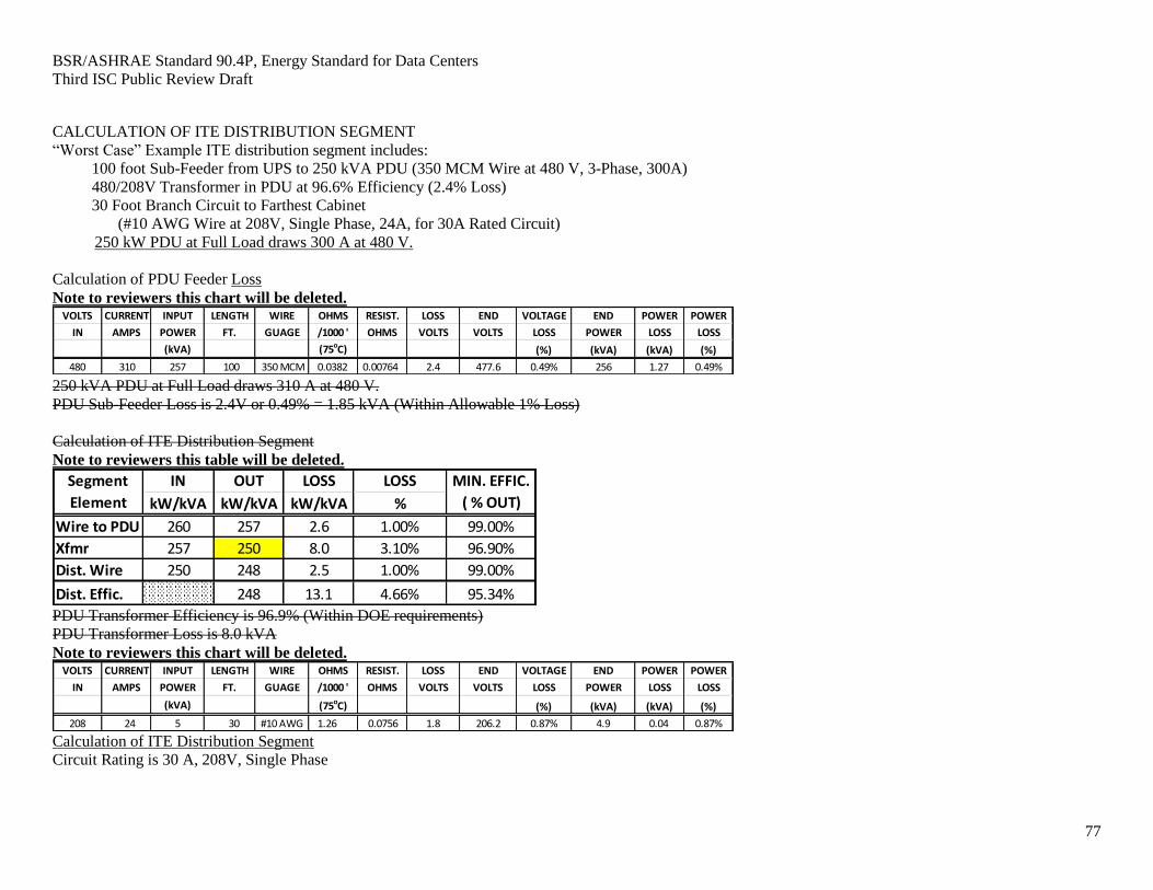
BSR/ASHRAE Standard 90.4P, Energy Standard for Data Centers
Third ISC Public Review Draft
2
SPECIAL NOTE This American National Standard (ANS) is a national voluntary consensus standard developed under the
auspices of the American Society of Heating, Refrigerating and Air-Conditioning Engineers (ASHRAE).
Consensus is defined by the American National Standards Institute (ANSI), of which ASHRAE is a
member and which has approved this standard as an ANS, as "substantial agreement reached by directly
and materially affected interest categories. This signifies the concurrence of more than a simple majority,
but not necessarily unanimity. Consensus requires that all views and objections be considered, and that an
effort be made toward their resolution." Compliance with this standard is voluntary until and unless a
legal jurisdiction makes compliance mandatory through legislation.
ASHRAE obtains consensus through participation of its national and international members, associated
societies, and public review.
ASHRAE Standards are prepared by a Project Committee appointed specifically for the purpose of
writing the Standard. The Project Committee Chair and Vice-Chair must be members of ASHRAE; while
other members may or may not be members of ASHRAE, all must be technically qualified in the subject
area of the standard. Every effort is made to balance the concerned interests on all Project Committees.
The Manager of Standards of ASHRAE should be contacted for:
a. interpretation of the contents of this Standard,
b. participation in the next review of the Standard,
c. offering constructive criticism for improving the Standard,
d. permission to reprint portions of the Standard.
DISCLAIMER ASHRAE uses its best efforts to promulgate standards for the benefit of the public in light of available
information and accepted industry practices. However, ASHRAE does not guarantee, certify, or assure
the safety or performance of any products, components, or systems tested, designed, installed, or operated
in accordance with ASHRAE's Standards or Guidelines or that any tests conducted under its standards
will be nonhazardous or free from risk.
ASHRAE INDUSTRIAL ADVERTISING POLICY ON STANDARDS ASHRAE Standards and Guidelines are established to assist industry and the public by offering a uniform
method of testing for rating purposes, by suggesting safe practices in designing and installing equipment,
by providing proper definitions of this equipment, and by providing other information that may serve to
guide the industry. The creation of ASHRAE Standards and Guidelines is determined by the need for
them, and conformance to them is completely voluntary.
In referring to this standard and marking of equipment and in advertising, no claim shall be made, either
stated or implied, that the product has been approved by ASHRAE.
Page 3
BSR/ASHRAE Standard 90.4P, Energy Standard for Data Centers
Third ISC Public Review Draft
3
TABLE OF CONTENTS
FOREWORD ................................................................................................................................................ 5
1. PURPOSE .............................................................................................................................................. 7
2. SCOPE ................................................................................................................................................... 7
3. DEFINITIONS ...................................................................................................................................... 8
3.1 General ........................................................................................................................................... 8
3.2 Definition ........................................................................................................................................ 8
4. ADMINISTRATION AND ENFORCEMENT ................................................................................... 16
4.1 General ......................................................................................................................................... 16
4.2 Compliance ................................................................................................................................... 18
5. BUILDING ENVELOPE .................................................................................................................... 21
5.1 General ......................................................................................................................................... 21
5.2 Compliance Paths ......................................................................................................................... 21
6. HEATING, VENTILATING, AND AIR CONDITIONING .............................................................. 22
6.1 General ......................................................................................................................................... 22
6.2 Definition of Compliance Paths ................................................................................................... 22
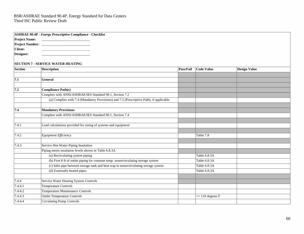
7. SERVICE WATER HEATING ......................................................................................................... 32
7.1 General ......................................................................................................................................... 32
7.2 Definition of Compliance Paths ................................................................................................... 32
8. ELECTRICAL ..................................................................................................................................... 33
8.1 General ......................................................................................................................................... 33
8.2 Definition of Compliance Paths ................................................................................................... 33
8.3 Compliance Path ........................................................................................................................... 34
8.4 Submittals ..................................................................................................................................... 35
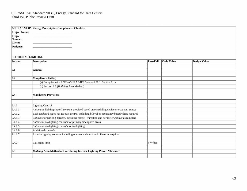
9. LIGHTING .......................................................................................................................................... 37
9.1 General ......................................................................................................................................... 37
9.2 Definition of Compliance Paths ................................................................................................... 37
10. OTHER EQUIPMENT ........................................................................................................................ 38
10.1 General ......................................................................................................................................... 38
11. GUIDE TO COMPLIANCE ................................................................................................................ 39
11.1 General ......................................................................................................................................... 39
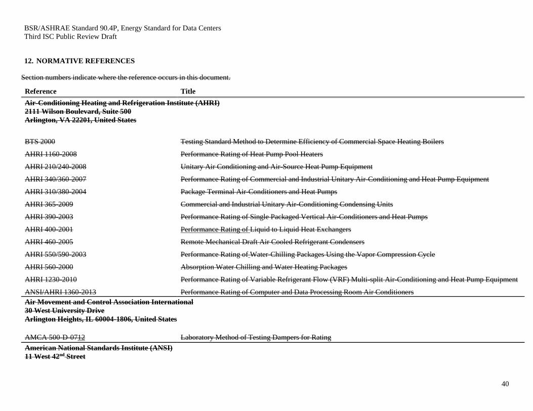
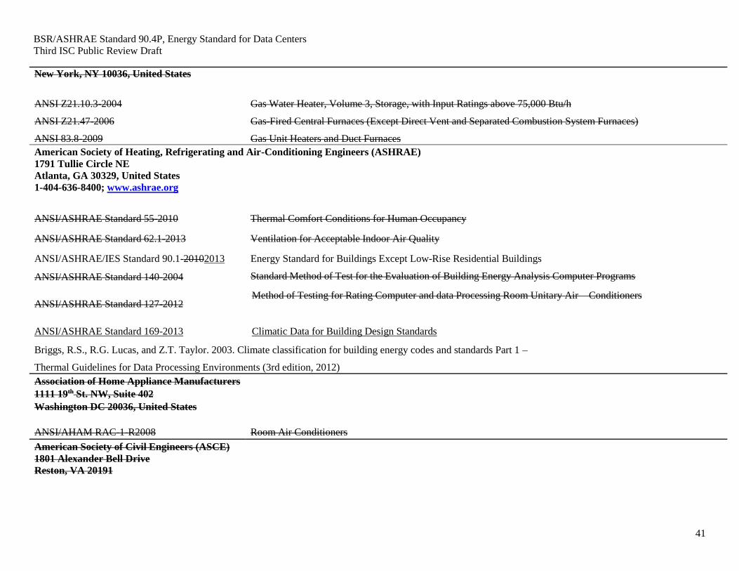
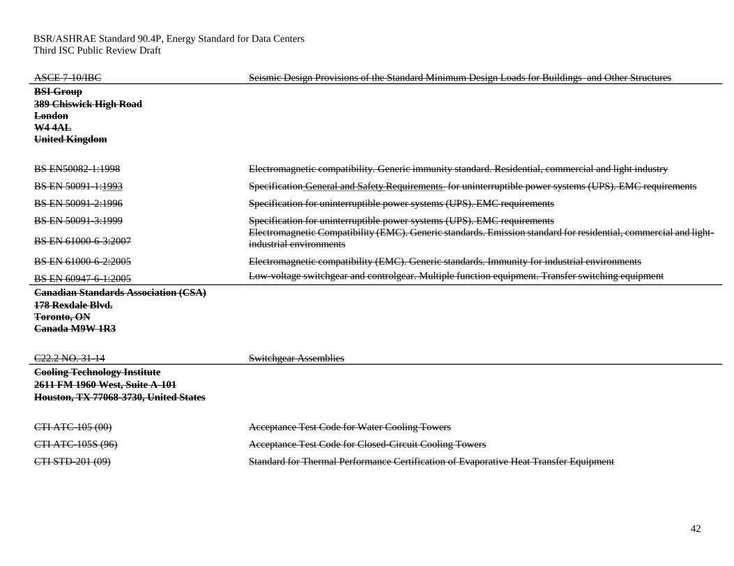
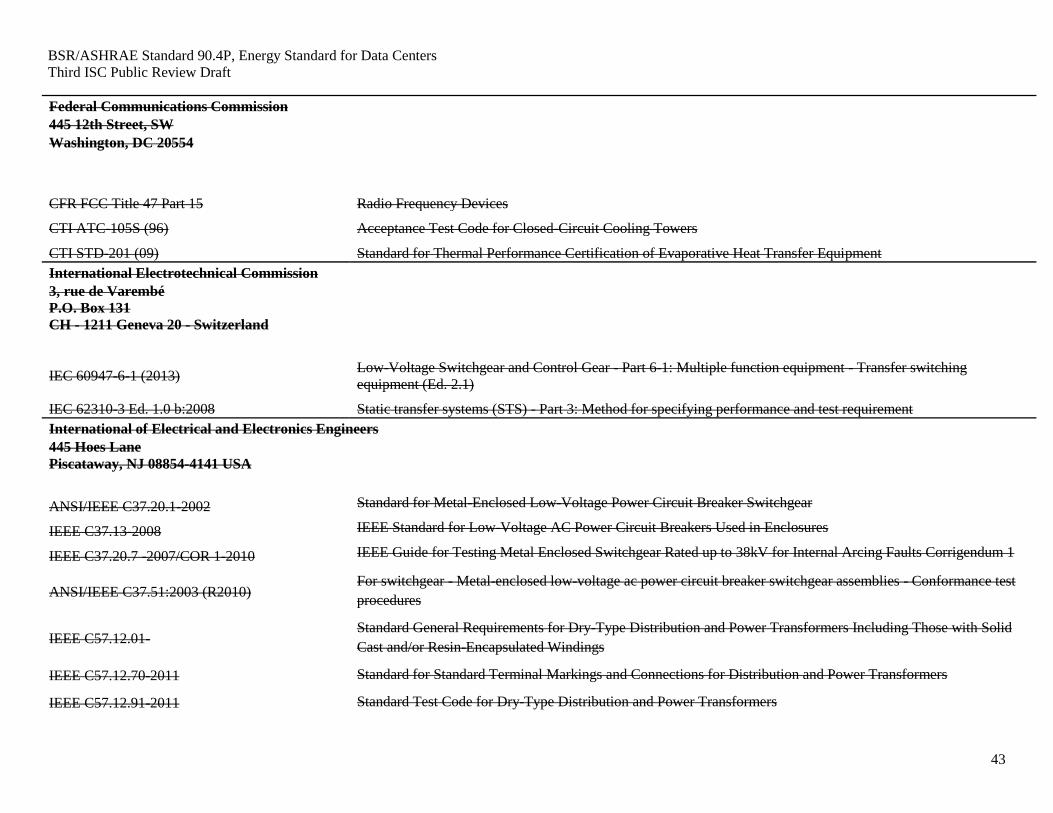
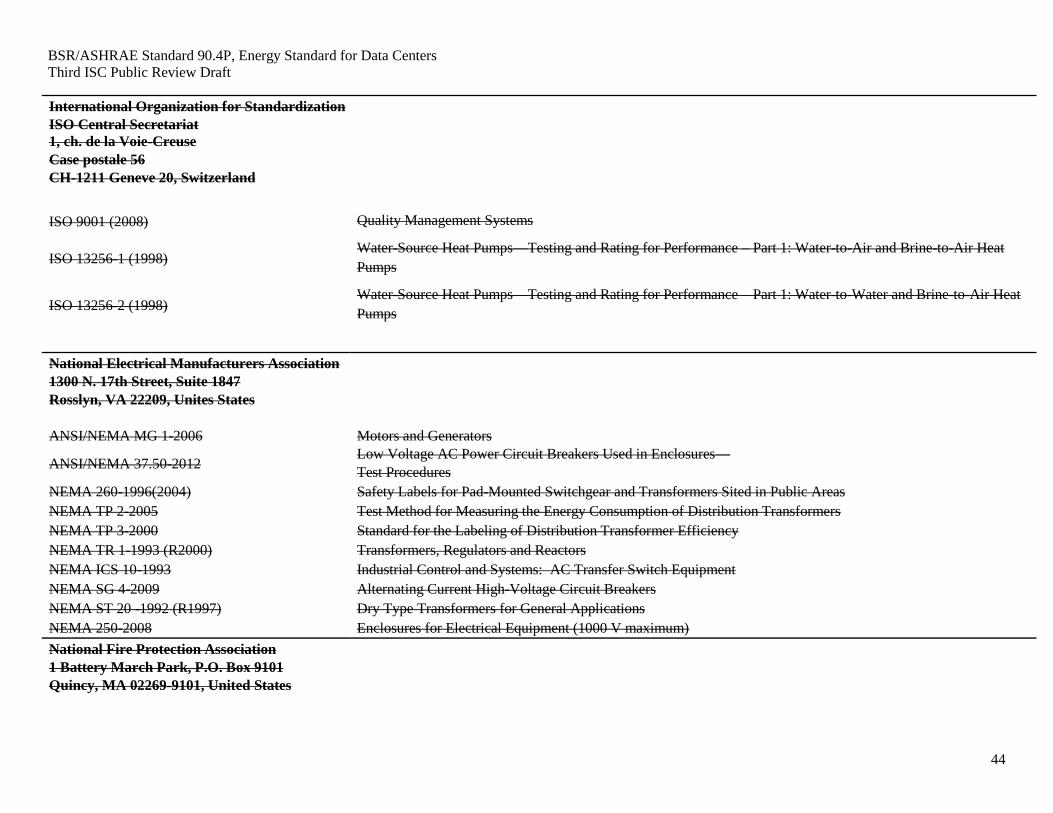
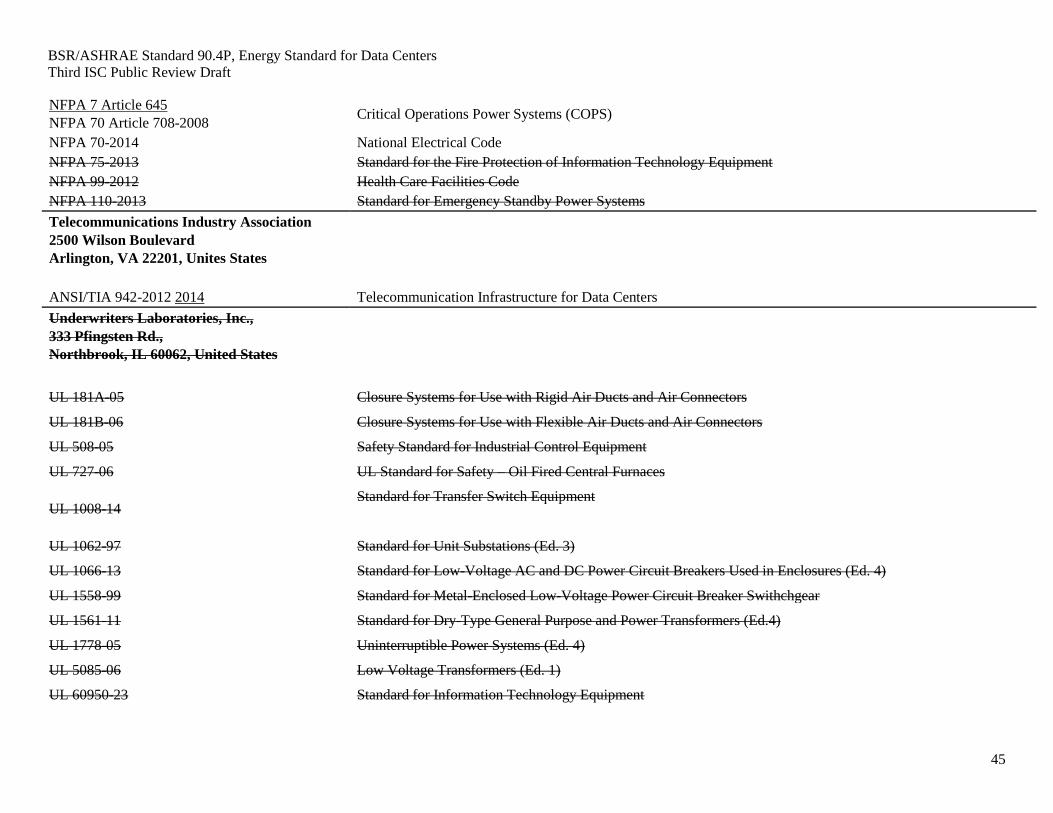
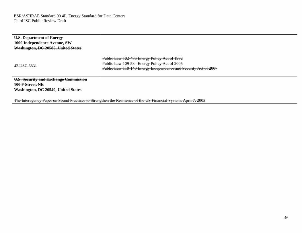
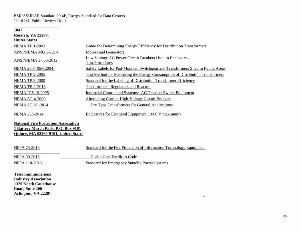
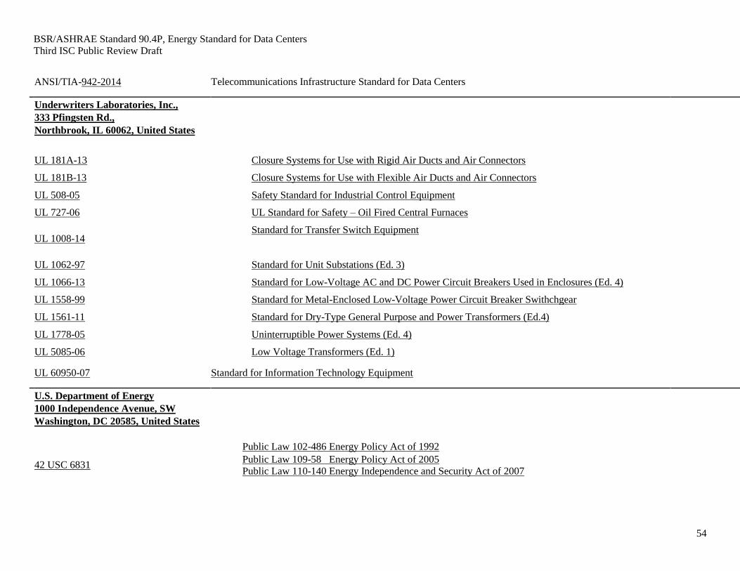
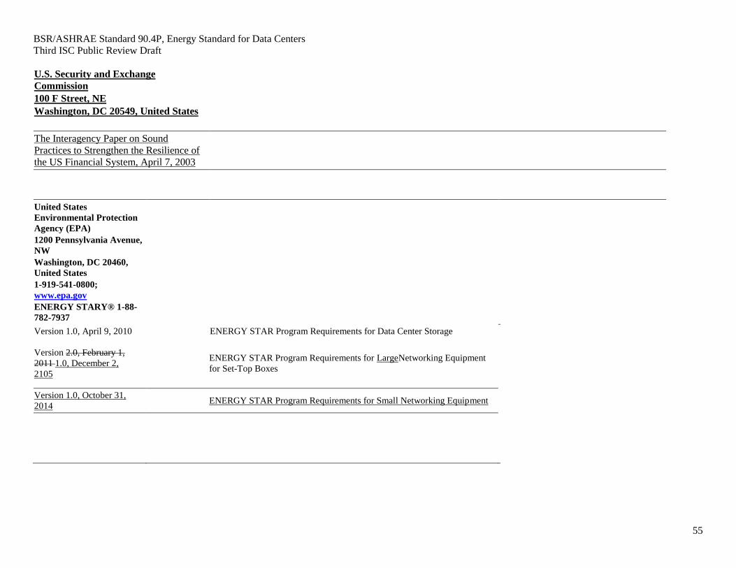
12. NORMATIVE REFERENCES ........................................................................................................... 40
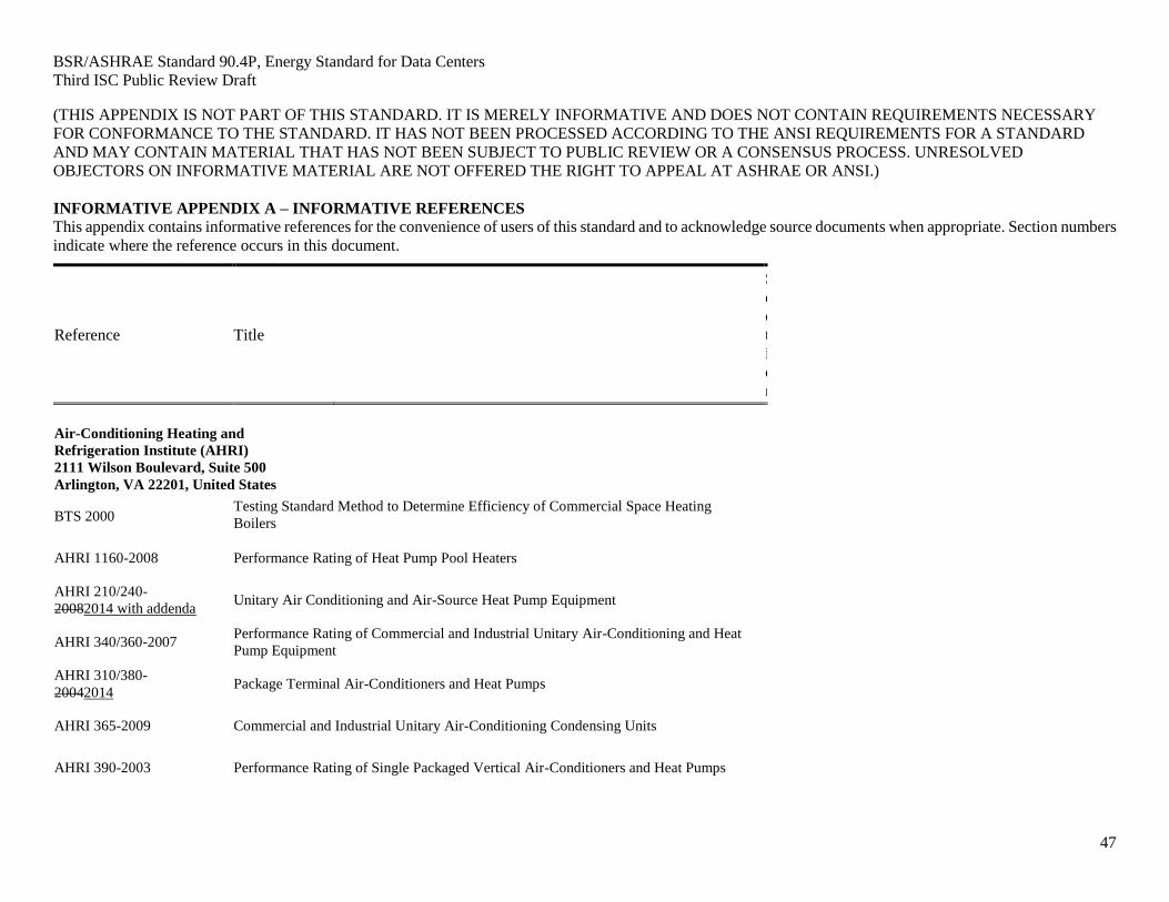
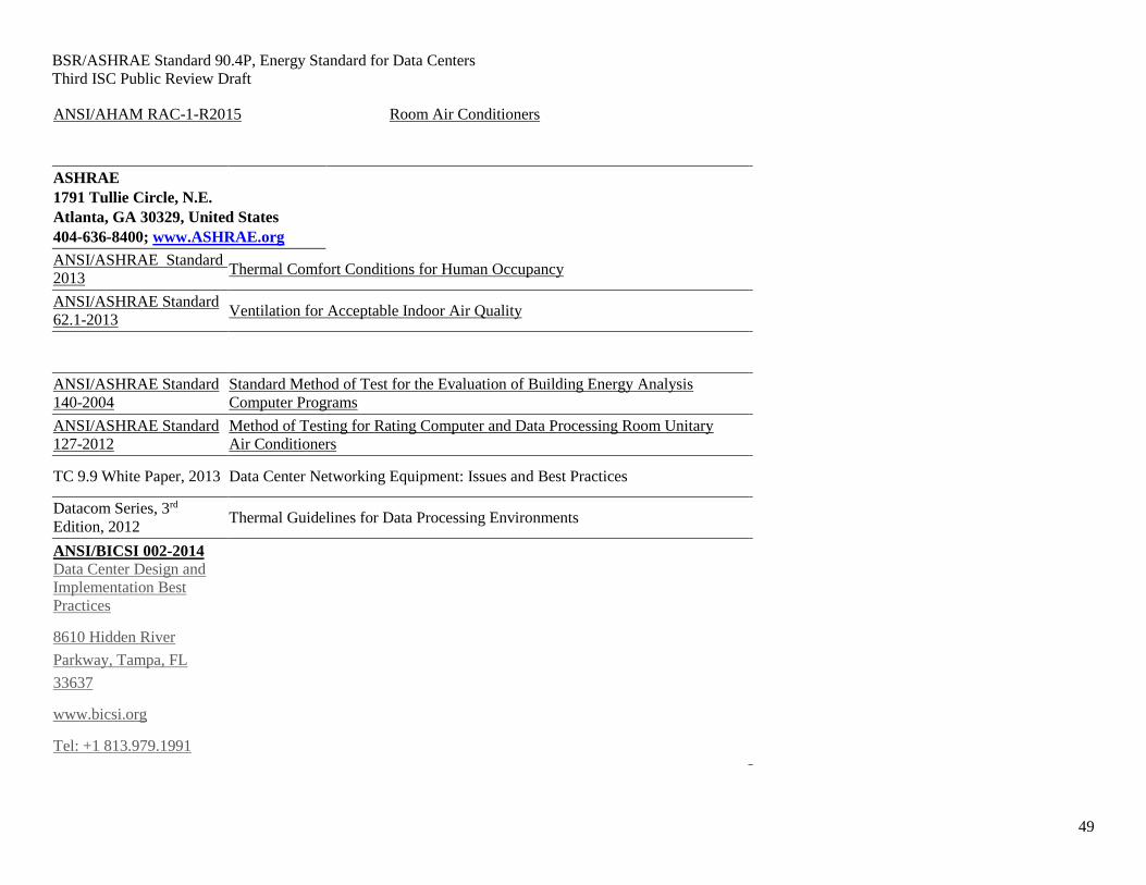
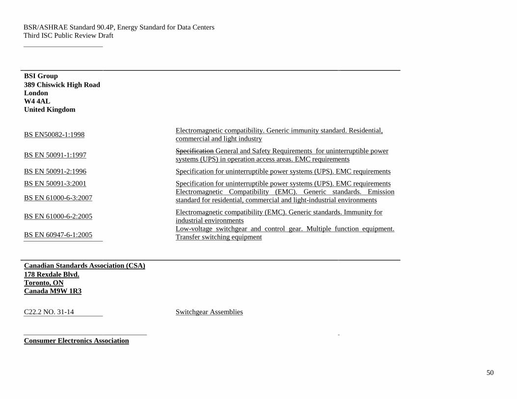
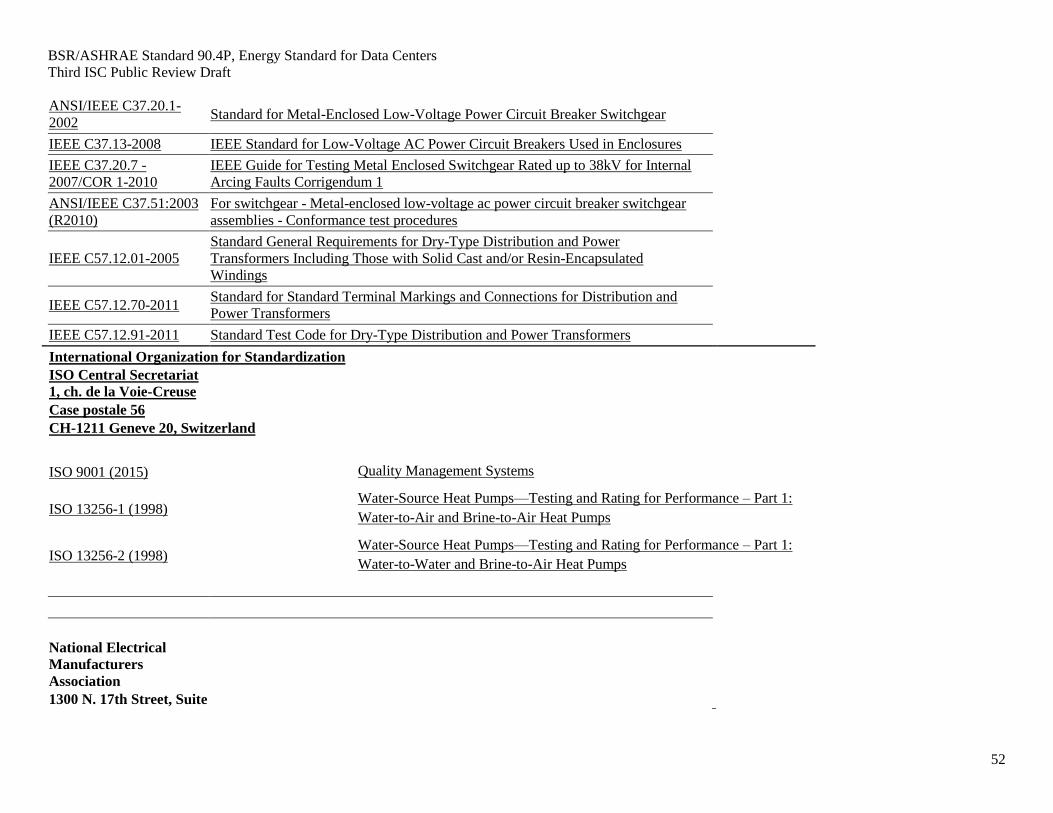
INFORMATIVE APPENDIX A ................................................................................................................ 47
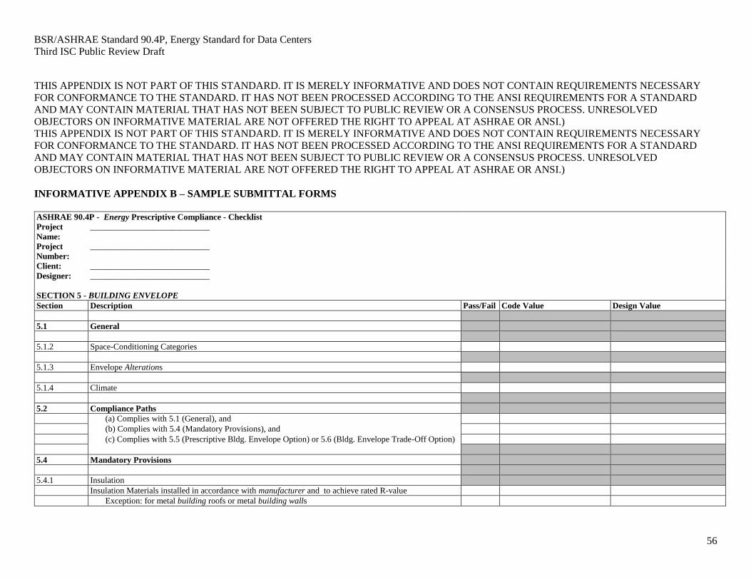
INFORMATIVE APPENDIX B ................................................................................................................. 50
INFORMATIVE APPENDIX C ................................................................................................................. 58
INFORMATIVE APPENDIX D
Page 4
BSR/ASHRAE Standard 90.4P, Energy Standard for Data Centers
Second Public Review Draft
4
Note to Reviewers: This draft has been recommended for a third independent substantive change public
review by the responsible project committee. To submit a comment on this proposed standard, go to the
ASHRAE website at
https://www.ashrae.org/standards-research--technology/public-review-drafts and access the online
comment database. Apart from acknowledging receipt of each comment, communication with
commenters by the authoring project committee is optional but may be undertaken to clarify a comment's
intent or to invite further participation in the standard’s development process. Please note that only the
changes that are in strike through and underline are open for public review comments.
Notes and examples are informational (non-mandatory) and are integrated in the text of this document to
give additional information intended to assist in the understanding or use of this document. Notes and
examples do not contain requirements or any information considered indispensable for the use of the
document.
(This foreword is not part of this standard. It is merely informative and does not contain
requirements necessary for conformance to the standard. It has not been processed according to the
ANSI requirements for a standard and may contain material that has not been subject to public
review or a consensus process. Unresolved objectors on informative material are not offered the right
to appeal at ASHRAE or ANSI.)
FOREWORD
We would like to thank all of the people who registered comments on the second Public Review draft.
The feedback has been very valuable in identifying improvements to the proposed Standard and the
Committee believes it has successfully made changes to resolve the majority of the comments.
Here are some of the significant changes that were made in response to public comments:
Revised the definition section to remove definitions used in ASHRAE Standard 90.1 and to
instead reference the definitions.
Revised several additional definitions to provide further clarity.
Revised Section 4.2 to reference the Alternate Compliance Option
Deleted Section 6.3 Alternative Compliance Path and created a revised Alternative Compliance
Path in Section 11.
Revised the numbers in Tables 8.2.1.1 and 8.2.1.2.
Revised portions in Section 8
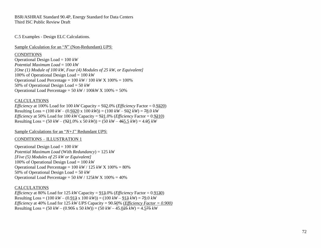
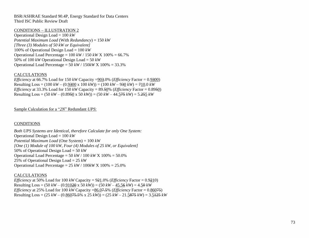
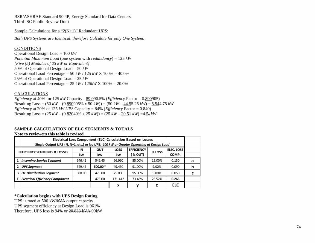
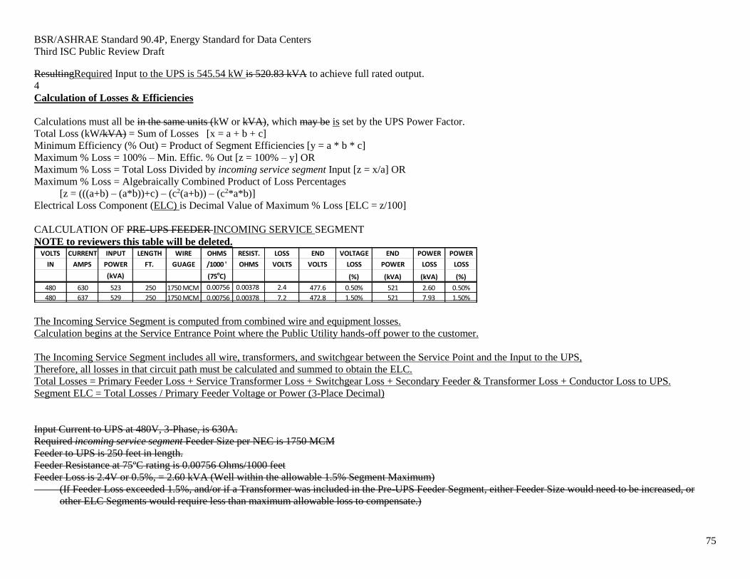
Revised Figures in Informative Appendix C and the Examples in C5
Updated the Normative and Informative References
Added Additional Sample Submittal Forms to Informative Appendix B
Reviewers of this draft should understand that the Committee intended for this standard to allow
innovation while still saving energy in data centers. There is also a related document that is out
concurrently for public review. This is Addendum cz to ANSI/ASHRAE/IES Standard 90.1-2013 to
eliminate scope overlap between 90.1 and 90.4.
Please be advised that the committee intends to put Standard 90.4, when published, on continuous
maintenance to allow the committee to make changes in real time with the IT industry.
Ron Jarnagin, Chairman Standard 90.4 Committee
Page 5
BSR/ASHRAE Standard 90.4P, Energy Standard for Data Centers
Third ISC Public Review Draft
5
Title: BSR/ASHRAE Standard 90.4P, Energy Standard for Data Centers
1. PURPOSE
The purpose of this standard is to establish the minimum energy efficiency requirements of Data Centers
for:
a. design, construction, and a plan for operation and maintenance, and
b. utilization of on-site, or off-site renewable energy resources
2. SCOPE
2.1 This Standard applies to:
a. new Data Centers or portions thereof and their systems,
b. new additions to Data Centers or portions thereof and their systems, and
c. modifications to systems and equipment in existing Data Centers or portions thereof
2.2 The provisions of this standard do not apply to:
a. telephone exchange(s)
b. essential facility(ies)
c. information technology equipment (ITE)
2.3 Where specifically noted in this standard, certain other buildings or elements of buildings shall be
exempt.
2.4 This Standard shall not be used to circumvent any safety, health, or environmental requirements.
Page 6
BSR/ASHRAE Standard 90.4P, Energy Standard for Data Centers
Third ISC Public Review Draft
6
3. DEFINITIONS
3.1 General. Certain terms, abbreviations, and acronyms are defined in this section for the purposes of
this standard. These definitions are applicable to all sections of this standard. Terms that are not
defined shall have their ordinary accepted meanings within the context in which they are used.
Ordinarily accepted meanings shall be based upon standard American English language usage as
documented in an unabridged dictionary accepted by the adopting authority.
3.1.1 Coordination. Where terms are not defined in this standard, but are defined in ASHRAE Standard
90.1, those terms shall have the meanings as assigned to them in ASHRAE Standard 90.1. Where terms
are not defined in either document they shall have their ordinary accepted meanings within the context in
which they are used. Ordinarily accepted meanings shall be based upon standard American English
language usage as documented in an unabridged dictionary accepted by the adopting authority.
3.2 Definition
adopting authority: the agency or agent that adopts this standard.
air; ambient: the air surrounding a building or space; the source of outdoor air brought into a building.
air; exhaust: air removed from a space and discharged to outside the building by means of mechanical or
natural ventilation systems.
air, recirculated: air removed from a space and reused as supply air.
air, return: air removed from a space to be then recirculated or exhausted.
air, supply: air delivered by mechanical or natural ventilation to a space, composed of any combination
of outdoor air, recirculated air, or transfer air.
alteration: a replacement not in kind or addition to a building or its systems and equipment. Routine
maintenance, repair, replace in kind, and service or a change in the building’s use classification or
category shall not constitute an alteration. Alterations exclude ITE adds, moves and changes
annualized mechanical load component (annualized MLC): the sum of all cooling, fan, pump, and heat
rejection annual energy use divided by the Data Center ITE energy.
authority having jurisdiction (AHJ): the agency or agent responsible for enforcing this standard.
automatic: self-acting, operating by its own mechanism when actuated by some non-manual influence
and without human intervention, such as a change in current strength, pressure, temperature, or
mechanical configuration. (See manual.)
branch circuit: the circuit conductors between the final overcurrent device protecting the circuit and the
outlet(s); the final wiring run to the load.
building: a structure wholly or partially enclosed within exterior walls, or within exterior and party walls,
and a roof, affording shelter to persons, animals, or property.
building envelope: the exterior plus the semi-exterior portions of a building.
building official: the officer or other designated representative authorized to act on behalf of the authority
having jurisdiction.
Page 7
BSR/ASHRAE Standard 90.4P, Energy Standard for Data Centers
Third ISC Public Review Draft
7
cabinet: A container that encloses connection devices, terminations, apparatus, wiring, and equipment.
circuit breaker: a device designed to open and close a circuit by non-automatic means and to open the
circuit automatically at a predetermined overcurrent without damage to itself when properly applied
within its rating.
computer room: A room or portions of a building serving an ITE load less than or equal to10 kW, or 20
watts/sf (215 Watts/m2) or less of conditioned floor area.
conditioned floor area: floor area of a building or structure that is conditioned space. See space,
conditioned.
construction: the fabrication and erection of a new building or any addition to or alteration of an existing
building.
construction documents: drawings and specifications used to construct a building, building systems, or
portions thereof.
control: to regulate the operation of equipment.
cooled space: space, conditioned.
Cooling energy (kWh): the sum of all site energy required to provide cooling via vapor- compression,
ventilation, dehumidification, humidification, evaporation, absorption, adsorption, or other means.
data center: A room or building, or portions thereof, including computer rooms being served by the data
center systems, serving a total ITE load greater than 10 kW and 20 watts/sf (215 Watts/m2) of conditioned
floor area.
data center energy: annual energy use of the data center including all IT equipment energy plus energy
that supports the IT equipment and data center space.
data center ITE design power (kW): the sum of all power for the ITE. ITE power is not assumed to be
seasonably variable in this Standard. Therefore, ITE energy can be calculated by multiplying ITE power
by 8,760, the number of hours in a normal year.
design data center ITE design powerload: The combined load power, in kW or kVA, of all the ITE loads
for which the ITE system was designed. The data center design ITE Load power shall be specified on the
construction documents, and shall not include any additional loads such as cabinet fans or other devices
that are not inherent parts of the ITE, even if they the loads are part of the UPS Operational Design Load.
data center ITE energy (kWh): the sum of all energy consumed by the ITE on an annual basis.
data center point of presence (PoP): The location where the common carrier connects to the data center
telecommunication equipment.
design conditions: specified environmental conditions, such as temperature and light intensity, required
to be produced and maintained by a system and under which the system must operate.
Data center design systems: HVAC systems, electrical systems, equipment, or portions thereof, used to
condition ITE or electrical systems, whichData center systems may also be shared serving other data
center additions or non-data center loads. portions of a building or portions thereof.
Page 8
BSR/ASHRAE Standard 90.4P, Energy Standard for Data Centers
Third ISC Public Review Draft
8
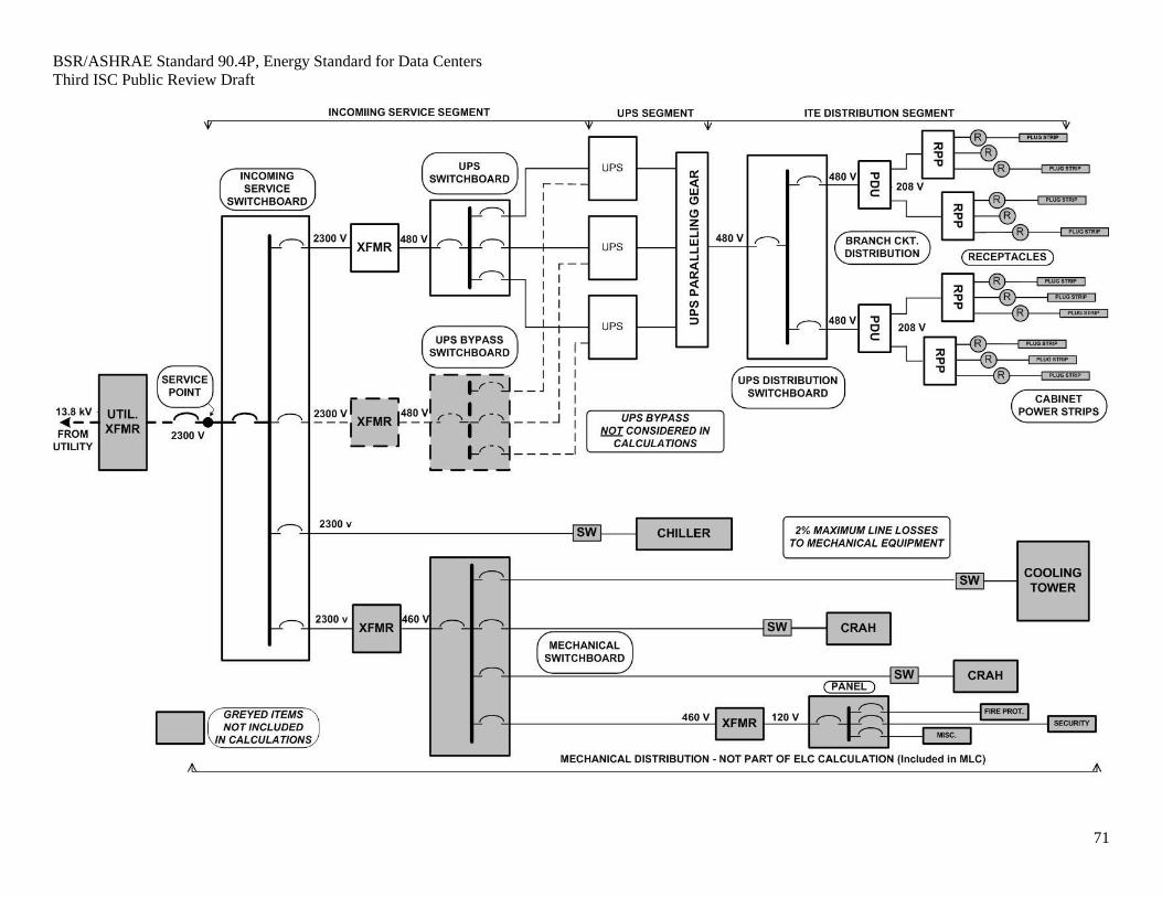
design electrical loss component (design ELC): the design electrical loss component of the ITE room
efficiency for the data center or data center addition shall be the combined losses (or the losses calculated
from efficiencies) of three segments of the electrical chain: incoming service segment; UPS segment and
ITE distribution segment. The design electrical Loss component shall be calculated using the worst case
parts of each segment of the power chain in order to demonstrate a minimum level of electrically efficient
design. The design ELC does not, and is not intended to, integrate all electrical losses in the facility.
design ELC demarcation: The incoming service point as defined by the National Electrical Code
(NFPA 70).
design mechanical load component (design MLC): the sum of all cooling, fan, pump, and heat rejection
design power divided by the data center ITE design power.
design power usage effectiveness (PUE): total data center power or energy divided by total IT equipment
power or energy as calculated by a design professional in accordance with industry-accepted standards.
design power usage effectiveness—category 0 (PUE0): peak electric demand power (kW), as
designed, for the entire data center, including IT equipment and supporting infrastructure,
divided by peak electric demand power (kW) of the IT equipment.
design power usage effectiveness—category 1 (PUE1): annual energy consumption (kWh), as
designed, for the entire data center, including IT equipment and supporting infrastructure,
divided by annual energy consumption (kWh) of the IT equipment.
design professional: an architect or engineer licensed to practice in accordance with applicable state
licensing laws.
dew point: the temperature to which air must be cooled (assuming constant air pressure and moisture
content) to reach a relative humidity of 100% (i.e. saturation).
distribution system: conveying means, such as ducts, pipes, and wires, to bring substances or energy from
a source to the point of use. The distribution system includes such auxiliary equipment as fans, pumps,
and transformers.
efficiency: performance at specified rating conditions, usually expressed as a percentage or as a decimal
factor of 1.0 or less.
enclosed space: a volume substantially surrounded by solid surfaces such as walls, floors, roofs, and
openable devices such as doors and operable windows.
energy: the capacity for doing work. It takes a number of forms that may be transformed from one into
another such as thermal (heat), mechanical (work), electrical, and chemical. Customary measurement
units are British thermal units (Btu) and kilowatt hours (kWh).
equipment: devices for conditioning of electric power and information technology equipment (ITE)
essential facility: Those portions of a building data center whether on the same site or at a remote
location, serving one of the following functions:
a. Hospitals and other health care facilities having surgery or emergency treatment facilities
b. Fire, rescue, and police stations and emergency vehicle garages
c. Designated earthquake, hurricane, or other emergency shelters
d. Designated emergency preparedness, communication, and operation centers and other facilities
required for emergency response
e. Power-generation, transmission and distribution stations, and other public utility facilities required
as emergency backup facilities for other essential facilities
Page 9
BSR/ASHRAE Standard 90.4P, Energy Standard for Data Centers
Third ISC Public Review Draft
9
f. Structures containing highly toxic materials where the quantity of the material exceeds the
maximum allowable quantities
g. Aviation control towers, air traffic control centers, and emergency aircraft hangars
h. Buildings Data centers and other structures having critical national defense functions
i. Those spaces having a mechanical cooling or electrical design of Rating IV as defined by ANSI/TIA-
942.
j. Those spaces classified under NFPA 70 Article 708 – Critical Operations Power Systems (COPS); or
k. Those spaces where core clearing and settlement services are performed such that failure to settle
pending financial transactions could present systematic risk as described in “The Interagency Paper on
Sound Practices to Strengthen Resilience of the Financial System, April 17, 2003.”
existing building: a building or portion thereof that was previously occupied or approved for occupancy
by the authority having jurisdiction.
existing equipment: equipment previously installed in an existing building.
existing system: a system or systems previously installed in an existing building.
fan brake horsepower: the horsepower delivered to the fan’s shaft. Brake horsepower (bhp) does not
include the mechanical drive losses (e.g., belts, gears).
floor area: the sum of the floor areas of the spaces within the building, including basements, mezzanine
and intermediate-floored tiers, and penthouses with a headroom height of 7.5 ft. or greater. It is measured
from the exterior faces of exterior walls or from the centerline of walls separating buildings, but
excluding covered walkways, open roofed-over areas, porches and similar spaces, pipe trenches, exterior
terraces or steps, chimneys, roof overhangs, and similar features.
fossil fuel: fuel derived from a hydrocarbon deposit such as petroleum, coal, or natural gas derived from
living matter of a previous geologic time.
fuel: a material that may be used to produce heat or generate power by combustion.
historic: a building or space that has been specifically designated as historically significant by the
adopting authority or is listed in The National Register of Historic Places or has been determined to be
eligible for such listing by the US Secretary of the Interior.
HVAC system: the equipment, distribution systems, and terminals that provide, either collectively or
individually, the processes of heating, ventilating, or air conditioning to a building or portion of a
building.
Incoming electrical service point: The terminal at which the Public Utility hands-off the incoming
power to the Owner, as defined by the National Electrical Code (NFPA 70).
incoming electrical service segment: the incoming electrical service segment of the design electrical loss
component (ELC) shall include all elements of the electrical power chain system delivering power to the
UPS and mechanical equipment, beginning with the load side of the incoming electrical service point
supplying the building, continuing through all other intervening transformers, wiring and switchgear, and
ending at the manufacturer-provided input terminals of the UPS and mechanical equipment. Although the
mechanical equipment is normally powered from the same incoming electrical service point, its path and
losses are not part of the ELC and, therefore, not part of the incoming electrical service segment
calculation.
incoming service segment: The segment of the electrical loss component (ELC) that shall include all
elements of the power chain delivering power to the UPS, beginning at the design ELC demarcation and
continuing through all intervening devices and switchgear to the input load terminals of the UPS segment.
Page 10
BSR/ASHRAE Standard 90.4P, Energy Standard for Data Centers
Third ISC Public Review Draft
10
information technology equipment (“ITE”): IT Equipment includes computers, data storage, servers and
network/communication equipment.
ITE adds, moves and changes: The normal and somewhat perpetual additions, moves, and changes to
ITE equipment such as a server moving from one ITE enclosure to another.
ITE distribution segment: The segment of the electrical loss component that includes all elements of the
power chain beginning at the manufacturer-provided output load terminals of the UPS segment, through
all transformers, wiring and switchgear, and up to and including the receptacles to which information
technology equipment (ITE) or power distribution strips for connection of multiple pieces of ITE to a
circuit, are intended to be connected. The ITE distribution segment shall not include the actual ITE, its
power cords or any accessory part of the ITE. In cases where power is to be hard-wired into self-
contained, manufacturer-configured cabinets, the calculation path shall terminate at the power input
terminals provided by the manufacturer within that equipment. The ITE distribution segment used to
calculate the electrical loss component shall be the longest path that also contains the largest numbers of
loss producing devices such as transformers, switchgear and/or panelboards.
ITE enclosure: A rack, cabinet, or chassis that is designed to mount and enable appropriate ventilation
of ITE.
IT equipment energy: annual energy used for computer, data storage and network equipment along with
supplemental equipment represented by the uninterruptible power supply (UPS) output.
ITE room: A room dedicated for ITE.
ITE room efficiency: the total efficiency of the electrical, mechanical and lighting systems serving the
ITE Room, combined mathematically and used in the computation of the data center’s design PUE.
kilovolt-ampere (kVA): where the term kilovolt-ampere (kVA) is used in this standard, it is the product of
the line current (amperes) times the nominal system voltage (kilovolts) times 1.732 for three-phase
currents. For single-phase applications, kVA is the product of the line current (amperes) times the nominal
system voltage (kilovolts).
kilowatt (kW): the basic unit of electric power, equal to 1000 W. For Alternating Current circuits and
single-phase equipment it is the kVAproduct of the voltage times the ampage times the Power Factor (pf)
of the connected equipment.
labeled: equipment or materials to which a symbol or other identifying mark has been attached by the
manufacturer indicating compliance with specified standards or performance in a specified manner.
lighting power density (LPD): the maximum lighting power per unit area (Watts/square foot or
Watts/square meter) of a building classification of space function.
loss: The difference between the power or energy entering a device or system segment and the power or
energy leaving that device or system segment. The loss may be measured in physical units (volts, watts,
psi, etc.) or may be calculated as one minus the Efficiency of the device or system segment.
manual (non-automatic): requiring personal intervention for control. Non-automatic does not necessarily
imply a manual controller, only that personal intervention is necessary. (See automatic.)
manufacturer: the company engaged in the original production and assembly of products or equipment or
a company that purchases such products and equipment manufactured in accordance with company
specifications.
Page 11
BSR/ASHRAE Standard 90.4P, Energy Standard for Data Centers
Third ISC Public Review Draft
11
mechanical cooling: reducing the temperature of a gas or liquid by using vapor compression, absorption,
desiccant dehumidification combined with evaporative cooling, or another energy-driven thermodynamic
cycle. Indirect or direct evaporative cooling alone is not considered mechanical cooling.
mechanical switchboard: the switchboard or circuit breaker panel from which sub-mains and/or branch
circuits emanate to deliver power to the mechanical elements of the ITE Room cooling equipment.
N: see redundancy.
outdoor (outside) air: air that is outside the building envelope or is taken from outside the building that
has not been previously circulated through the building.
proposed design: a computer representation of the actual proposed building design or portion thereof used
as the basis for calculating the design energy cost.
record drawings: drawings that record the conditions of the project as constructed. These include any
refinements of the construction or bid documents.
redundancy: the duplication of critical deliberate duplication of components, equipment, controls or
systems and their interconnections to enable continued operations at needed functional capacities during
and after the loss of the primary components, equipment, controls or systems due to failure, maintenance,
servicing or other modification activities. or functions of a system with the intention of increasing
reliability of the system , usually in the form of a backup or fail-safe
N = Base System Number of capacity components needed to provide design system functional
capacity
N+1, N+2, etc. = Parallel Redundant single system redundancy having one or more additional
capacity components
2N, 2N+1 or 2(N+1), etc. = Complete Redundancy dual systems redundancy having one or more
additional capacity components
repair: the reconstruction or renewal of any part of an existing building for the purpose of its
maintenance.
roof: the upper portion of the building envelope, including opaque areas and fenestration, that is
horizontal or tilted at an angle of less than 60° from horizontal.
service: the equipment for delivering energy from the supply or distribution system to the premises
served.
service point: The point of connection between the facilities of the serving utility and the premises
wiring. The service point can be described as the point of demarcation between where the serving utility
ends and the premises continuation begins. The serving utility generally specifies the location of the
service point based on the conditions of service.
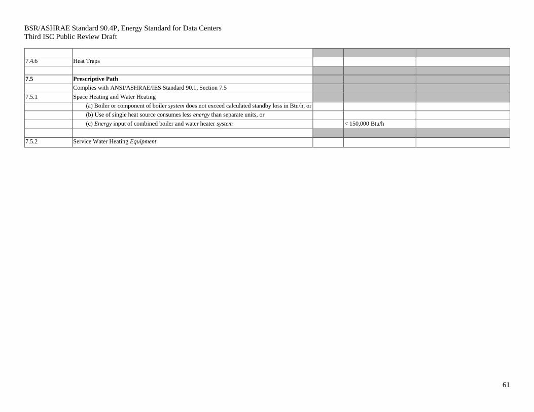
service water heating: heating water for domestic or commercial purposes other than space heating and
process requirements.
single-line diagram: a simplified schematic drawing that shows the connections among two or more
items. Common multiple connections are shown as one line.
skylight: an area of the building envelope that lets in light that has a slope of less than 60 degrees from the
horizontal plan.
space: an enclosed space within a building. The classifications of spaces are as follows for the purpose of
determining building envelope requirements:
Page 12
BSR/ASHRAE Standard 90.4P, Energy Standard for Data Centers
Third ISC Public Review Draft
12
conditioned space: a cooled space, heated space, or indirectly conditioned space defined as follows:
1. cooled space: an enclosed space within a building that is cooled by a cooling system whose
sensible output capacity exceeds 5 Btu/h·ft2 of floor area.
2. heated space: an enclosed space within a building that is heated by a heating system whose
output capacity relative to the floor area is greater than or equal to the criteria in Table 3.1.
3. indirectly conditioned space: an enclosed space within a building that is not a heated space or a
cooled space, but which is heated or cooled indirectly by being connected to adjacent space(s)
provided:
a. the product of the U-factor(s) and surface area(s) of the space adjacent to connected space(s)
exceeds the combined sum of the product of the U-factor(s) and surface area(s) of the space
adjoining the outdoors, unconditioned spaces, and to or from semi-heated spaces (e.g.,
corridors) or
b. that air from heated or cooled spaces is intentionally transferred (naturally or mechanically)
into the space at a rate exceeding 3 ach (e.g., atria).
semi-heated space: an enclosed space within a building that is heated by a heating system whose
output capacity is greater than or equal to 3.4 Btu/h·ft2 of floor area but is not a conditioned space.
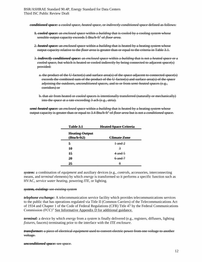
Table 3.1 Heated Space Criteria
Heating Output
(Btu/h·ft2) Climate Zone
5 1 and 2
10 3
15 4 and 5
20 6 and 7
25 8
system: a combination of equipment and auxiliary devices (e.g., controls, accessories, interconnecting
means, and terminal elements) by which energy is transformed so it performs a specific function such as
HVAC, service water heating, powering ITE, or lighting.
system, existing: see existing system
telephone exchange: A telecommunication service facility which provides telecommunications services
to the public that has operations regulated via Title II (Common Carriers) of the Telecommunications Act
of 1934 and Chapter 1 of the Code of Federal Regulations (CFR) Title 47 by the Federal Communications
Commission (FCC)” See Informative Appendix D for additional guidance.
terminal: a device by which energy from a system is finally delivered (e.g., registers, diffusers, lighting
fixtures, faucets) terminating prior to the interface with the ITE enclosure.
transformer: a piece of electrical equipment used to convert electric power from one voltage to another
voltage.
unconditioned space: see space.
Page 13
BSR/ASHRAE Standard 90.4P, Energy Standard for Data Centers
Third ISC Public Review Draft
13
uninterruptable power supply (UPS): a system intended to deliver continuous, stable power to the critical
load. The majority of modern UPS systems are of two fundamental types: “Double conversion static” in
which incoming AC power is rectified to DC and then inverted back to AC, with batteries in the DC
portion that assume the load when incoming power fails or anomalies occur; and “flywheel rotary” in
which incoming AC power drives a propulsion unit that turns a generating device, with a largeheavy
flywheel storing kinetic energy that continues to turn the generating portion when incoming power fails or
anomalies occur. Either type can be made up of one or more modules running in parallel to add capacity
or redundancy or both. Direct Current UPS systems, which eliminate the inverter and deliver DC power
to the ITE are also used.
UPS “economy mode”: a mode of UPS operation in which power is normally fed to the load without
going through power conversions within the UPS for the purpose of reducing loss during normal
operation so as to save energy. Circuitry is incorporated to rapidly switch the load to the
rectifier/battery/inverter in the event of a power failure or voltage drop below a preset threshold.
“Economy Mode” is normally a configurable option that can be utilized or overridden at user discretion.
UPS operational design load: The load in kW or kVA at which the UPS is intended to operate by design.
This will be the Design data center ITE Load design power plus any other loads such as cabinet door fans
or refrigerant pumps that will be connected to the UPS. The UPS operational design load is typically less
than the UPS rated capacity.
UPS rated capacity: The maximum load in kW or kVA at which an individual UPS is designed and
specified by the manufacturer to operate on a continuous basis under specified environmental conditions.
The UPS rated capacity does not include the capacity of any redundant UPS components or systems.
UPS segment: the UPS segment of the design electrical loss component (design ELC)shall include the
manufacturer-provided UPS system from the input terminals to the output terminals, including all
transformers, switchgear, rectifiers, inverters flywheel rotary propulsion units and wiring provided by the
manufacturer between those two points. Transformers and switchgear provided by the UPS
manufacturer but housed in different cabinets from the actual UPS capacity components shall be
considered parts of the UPS segment along with associated wiring. Transformers and switchgear
functioning as parts of the UPS, but installed separately and not provided by the UPS manufacturer (such
as custom-configured bypass) shall not be considered part of the UPS segment. All such associated
components shall be included with the incoming service segment and/or the ITE distribution segment in
accordance with their specific design logic.
ventilation: the process of supplying air to or removing air from a space for the purpose of controlling air
contaminant levels, humidity, or temperature within the space.
wall: that portion of the building envelope, including opaque area and fenestration, that is vertical or tilted
at an angle of 60 degrees from horizontal or greater. This includes above and below grade walls, between
floor spandrels, peripheral edges of floors, and foundation walls.
Page 14
BSR/ASHRAE Standard 90.4P, Energy Standard for Data Centers
Third ISC Public Review Draft
14
4. ADMINISTRATION AND ENFORCEMENT
4.1 General
4.1.1 Scope
4.1.1.1 New Data Centers. New Data Centers shall comply with the standard as described in
Section 4.2.
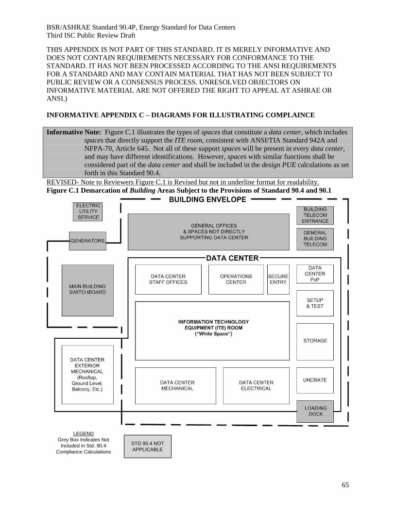
Informative Note: Refer to Figure C.1 for Building Areas Subject to the Provisions of Standard 90.4
4.1.1.2 Additions to Existing Data Centers. An extension or increase in the floor area or height
of a data center outside of the existing data center envelope shall be considered additions to existing data
centers and shall comply with the standard as described in Section 4.2.
4.1.1.3 Alterations of Existing Data Centers. Alterations of existing data centers shall
comply with the standard as described in Section 4.2.
4.1.1.4 Replacement of Portions of Existing Data Center. Portions of a data center envelope,
heating, ventilating, air-conditioning, service water heating, power, lighting, and other systems and equipment
that are being replaced shall be considered as alterations of existing data centers and shall comply with
the standard as described in Section 4.2.
4.1.1.5 Changes in Space Conditioning. When unconditioned or semi-heated spaces in a data
center are converted to conditioned spaces, such conditioned spaces shall be brought into compliance
with the requirements of this standard that apply to the data center envelope, heating, ventilating, air-
conditioning, service water heating, power, lighting, and other systems and equipment of the space as if the
data center was new.
4.1.2 Administrative Requirements. Administrative requirements relating to permit requirements,
enforcement by the authority having jurisdiction, locally adopted energy standards, interpretations,
claims of exemption, and rights of appeal are specified by the authority having jurisdiction.
4.1.3 Alternative Materials, Methods of Construction, or Design. The provisions of this standard
are not intended to prevent the use of any material, method of construction, design, equipment, or data
center system not specifically prescribed herein.
4.1.4 Validity. If any term, part, provision, section, paragraph, subdivision, table, chart, or referenced
standard of this standard shall be held unconstitutional, invalid, or ineffective, in whole or in part, such
determination shall not be deemed to invalidate any remaining term, part, provision, section, paragraph,
subdivision, table, chart, or referenced standard of this standard.
4.1.5 Other Laws. The provisions of this standard shall not be deemed to nullify any provisions of
local, state, or federal law. Where there is a conflict between a requirement of this standard and such other
law affecting construction of the data center, precedence shall be determined by the authority having
jurisdiction.
4.1.6 Referenced Standards. The standards referenced in this standard and listed in Section 12
shall be considered part of the requirements of this standard to the prescribed extent of such reference.
Where differences occur between the provision of this standard and referenced standards, the provisions
of this standard shall apply. Informative references are cited to acknowledge sources and are not part of this
standard. They are identified in Informative Appendix A.
Page 15
BSR/ASHRAE Standard 90.4P, Energy Standard for Data Centers
Third ISC Public Review Draft
15
4.1.7 Normative Appendices. The normative appendices to this standard are considered to be
integral parts of the mandatory requirements of this standard, which, for reasons of convenience, are
placed apart from all other normative elements.
4.1.8 Informative Appendices. The informative appendices to this standard and informative notes
located within this standard contain additional information and are not mandatory or part of this standard.
Page 16
BSR/ASHRAE Standard 90.4P, Energy Standard for Data Centers
Third ISC Public Review Draft
16
4.2 Compliance
4.2.1 Compliance Paths
4.2.1.1 New Data Centers. New data centers shall comply with the provisions of Sections 5, 6,
7, 8, 9, and 10 and 11. and one of the following:
a. Sections 6 and 8 or
b. Section 11.
Informative Note: See informative reference C.1 for an illustrative diagram.
4.2.1.2 Additions to Existing Data Centers. Additions to existing data center shall comply with
the provisions of Sections 5, 6, 7, 8, 9, and 10 and 11. and one of the following:
a. Sections 6 and 8 or
b. Section 11.
Exception: 1. Additions that result in less than a 10% increase in area or less than a 10% increase in connected
load (kW) are excluded.
2. When an addition to an existing data center cannot comply by itself, trade-offs will is unable to
demonstrate compliance the facility shall be allowed to demonstrate through trade-offs via be
allowed by modification to one or more of the existing components of the existing data center.
Modeling of the modified components of the existing data center addition shall employ the
procedures in Section 11 of ANSI/ASHRAE/IES Standard 90.1.
4.2.1.3 Alterations of Existing Data Centers. Alterations of existing data centers shall comply
with the provisions of Sections 5, 6, 7, 8, 9, and 10 and 11 and with either Sections 6 and 8 or Section 11,
provided such compliance will not result in the increase of energy consumption of the building.
Exceptions:
1. ITE adds, moves and changes are excluded.
2. ITE enclosures are excluded.
3. A data center that has been specifically designated as historically significant by the adopting
authority, listed in The National Register of Historic Places or has been determined to be
eligible for listing by the US Secretary of the Interior, need not comply with these
requirements.
4. Where one or more components or portions of an existing data center mechanical, electrical
or lighting system is being replaced without changing capacities; the annual energy
consumption of the of the system in which replacements are made shall not be greater than
the annual energy consumption of the existing system. Compliance can be demonstrated
using manufacturer’s published efficiency data for the new and existing devices, or by
comparative calculations of the annual energy consumptions of the existing and revised
systems, performed by a design professional using calculation methods commonly accepted
in the industry.
Component or system replacements or modifications that result in changes in either capacity
or type of technology require compliance with the applicable sections and versions of this
Standard in accordance with 4.2.2.4.
4.2.1.4 Compliance Standard Review Reference. For alterations or additions to an existing
building the version used for compliance shall be the most current version of the standard or that as
specified in Table 4.2.1.4.
Page 17
BSR/ASHRAE Standard 90.4P, Energy Standard for Data Centers
Third ISC Public Review Draft
17
TABLE 4.2.1.4 Compliance Standard for Project Plan Review
Build Type ENVELOPE MECHANICAL MECHANICAL LIGHTING POWER POWER
•4.2.1.1 New
SYSTEMS
INDIVIDUAL
COMPONENTS SYSTEMS
INDIVIDUAL
COMPONENTS
Full Build-out M M M M M M
Initial Phase Scaled Build M M M M M C
Initial Phase Modular Build M M M M M C
Initial Modular SHELL Build M M M M M M
Shell and Core Build M M M M M M
•4.2.1.2 Additions to existing
Phase Scaled Build C M C C M C
Phase Modular Build C C C C C C
Modular SHELL Build C C C C C C
Core Build C C C C C C
•4.2.1.3 Alterations to Existing
All M M C C M C
• 4.2.1.3b Replacement of Portions of Existing
Full Build-out M M C C M C
Phase Scaled Build M M C C M C
Phase Modular Build M M C C M C
Modular SHELL Build M M C C M C
Shell and Core Build-out M M C C M C
(C) – Current edition of the Standard
(M) – Master plan standard edition, the edition of the standard used to create the original data center plan
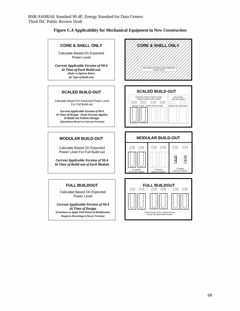
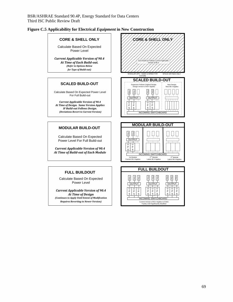
Informative Note: Refer to Figures C.3, C.4 and C.5 for guidance on applicability.
4.2.2 Compliance Documentation
4.2.2.1 Construction Details. Compliance documents shall show all the pertinent data and features
of the data center, equipment, and systems in sufficient detail to permit a determination of compliance by the
building official and to indicate compliance with the requirements of this standard.
4.2.2.2 Supplemental Information. Supplemental information necessary to verify compliance with
this standard, such as calculations, worksheets, compliance forms, vendor literature, or other data, shall be
made available when required by the building official. Compliance may be documented using mechanical
and electrical calculations to complete each required path shown below. If compliance is to be shown for
mechanical systems only; designer performs calculation 6.2.1.1 or 6.2.1.2. If compliance is to be shown
for electrical system only, designer performs calculation 8.2.1.1. Calculation 6.2.1.2 can be used to take
credit for existing mechanical system efficiencies, when compliance is to be shown for electrical system
only. Calculation 8.2.1.1 and 6.2.1.2 can be used to take credit for existing electrical system efficiencies,
when compliance is to be shown for mechanical system only.
Informative Note: See Informative Figure C.2 Mechanical and Electrical Compliance Path.
4.2.2.3 Manuals. Operating and maintenance information shall be provided to the data center owner.
This information shall include, but not be limited to, the information specified below:
a. Submittal data stating equipment size.
Page 18
BSR/ASHRAE Standard 90.4P, Energy Standard for Data Centers
Third ISC Public Review Draft
18
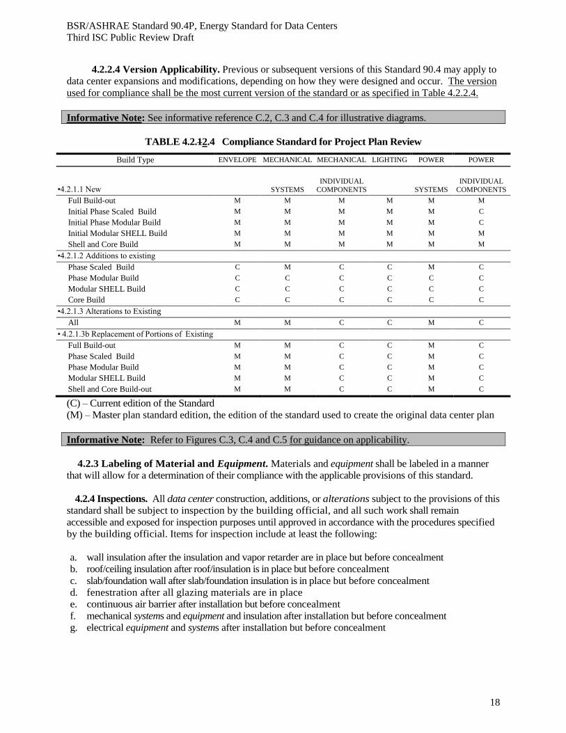
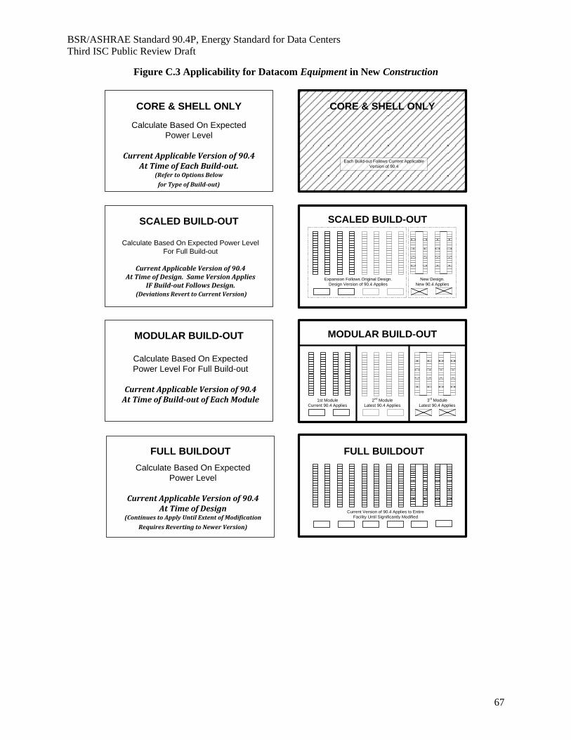
4.2.2.4 Version Applicability. Previous or subsequent versions of this Standard 90.4 may apply to
data center expansions and modifications, depending on how they were designed and occur. The version
used for compliance shall be the most current version of the standard or as specified in Table 4.2.2.4.
Informative Note: See informative reference C.2, C.3 and C.4 for illustrative diagrams.
TABLE 4.2.12.4 Compliance Standard for Project Plan Review
Build Type ENVELOPE MECHANICAL MECHANICAL LIGHTING POWER POWER
•4.2.1.1 New
SYSTEMS INDIVIDUAL
COMPONENTS SYSTEMS INDIVIDUAL
COMPONENTS
Full Build-out M M M M M M
Initial Phase Scaled Build M M M M M C
Initial Phase Modular Build M M M M M C
Initial Modular SHELL Build M M M M M M
Shell and Core Build M M M M M M
•4.2.1.2 Additions to existing
Phase Scaled Build C M C C M C
Phase Modular Build C C C C C C
Modular SHELL Build C C C C C C
Core Build C C C C C C
•4.2.1.3 Alterations to Existing
All M M C C M C
• 4.2.1.3b Replacement of Portions of Existing
Full Build-out M M C C M C
Phase Scaled Build M M C C M C
Phase Modular Build M M C C M C
Modular SHELL Build M M C C M C
Shell and Core Build-out M M C C M C
(C) – Current edition of the Standard
(M) – Master plan standard edition, the edition of the standard used to create the original data center plan
Informative Note: Refer to Figures C.3, C.4 and C.5 for guidance on applicability.
4.2.3 Labeling of Material and Equipment. Materials and equipment shall be labeled in a manner
that will allow for a determination of their compliance with the applicable provisions of this standard.
4.2.4 Inspections. All data center construction, additions, or alterations subject to the provisions of this
standard shall be subject to inspection by the building official, and all such work shall remain
accessible and exposed for inspection purposes until approved in accordance with the procedures specified
by the building official. Items for inspection include at least the following:
a. wall insulation after the insulation and vapor retarder are in place but before concealment
b. roof/ceiling insulation after roof/insulation is in place but before concealment
c. slab/foundation wall after slab/foundation insulation is in place but before concealment
d. fenestration after all glazing materials are in place
e. continuous air barrier after installation but before concealment
f. mechanical systems and equipment and insulation after installation but before concealment
g. electrical equipment and systems after installation but before concealment
Page 19
BSR/ASHRAE Standard 90.4P, Energy Standard for Data Centers
Third ISC Public Review Draft
19
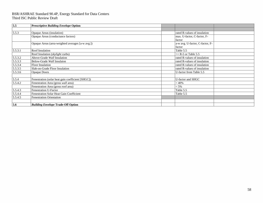
5. BUILDING ENVELOPE
5.1 General
5.1.1 Scope: This section defines the minimum requirements of the data center building envelope.
5.2 Compliance Paths
5.2.1 Compliance. Provisions of this section shall comply with Section 5 of ANSI/ASHRAE/IES
Standard 90.1, or demonstrate energy efficiency improvement compared to a data center designed to
comply with Section 5 of ANSI/ASHRAE/IES Standard 90.1.
Page 20
BSR/ASHRAE Standard 90.4P, Energy Standard for Data Centers
Third ISC Public Review Draft
20
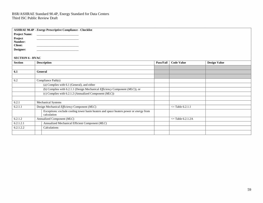
6. HEATING, VENTILATING, AND AIR CONDITIONING
6.1 General
6.1.1 Scope
6.1.1.1 New Buildings Data Centers. Mechanical equipment and systems serving the heating,
cooling, ventilating needs of new buildings data centers shall comply with the requirements of this
section as described in Section 6.2 or Section 6.3.
6.1.1.2 Additions to Existing Buildings Data Centers. Mechanical equipment and systems serving
the heating, cooling, or ventilating needs of additions to existing buildings data centers shall comply with
the requirements of this section as described in Section 6.2 or Section 6.3.
Exception: Where conditioned air is provided to an a data center addition by using the HVAC
systems and equipment of the existing building, such existing systems and equipment shall not be required
to comply with this standard.
6.1.1.3 Alterations to Heating, Ventilating, Air Conditioning, and Refrigeration (HVACR) in
Existing Buildings Data Centers
6.1.1.3.1 Replacing existing HVAC equipment with new HVAC equipment shall comply with
the specific minimum efficiency requirements applicable to that equipment in ANSI/ASHRAE/IES 90. 1
or Table 6.3.1.1.
Exceptions: 1. for equipment that is being modified or repaired but not replaced, provided that such
modifications and/or repairs will not result in an increase in the annual energy consumption
of the equipment using the same energy type;
2. where a replacement or alteration of equipment requires extensive revisions to other
systems, equipment, or elements of a building, and such replaced or altered equipment is a
like-for-like replacement;
3. for a refrigerant change of existing equipment;
4. for the relocation of existing equipment.
6.1.1.3.2 New cooling systems installed to serve previously uncooled spaces shall comply with
this section as described in Section 6.2.
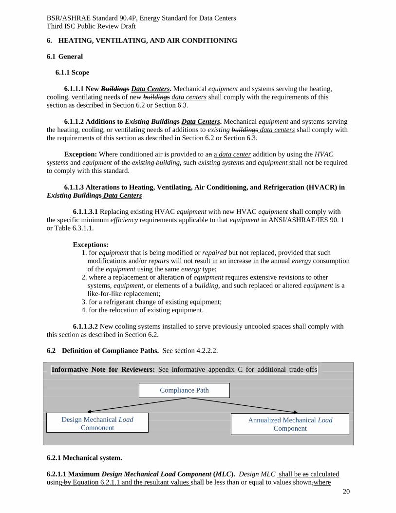
6.2 Definition of Compliance Paths. See section 4.2.2.2.
6.2.1 Mechanical system.
6.2.1.1 Maximum Design Mechanical Load Component (MLC). Design MLC shall be as calculated
using by Equation 6.2.1.1 and the resultant values shall be less than or equal to values shown,where
Compliance Path
Design Mechanical Load
Component Annualized Mechanical Load
Component
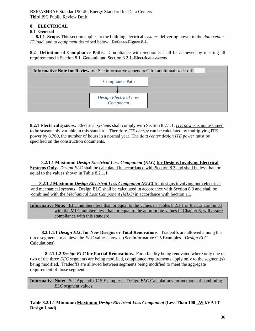
Informative Note for Reviewers: See informative appendix C for additional trade-offs
options
Page 21
BSR/ASHRAE Standard 90.4P, Energy Standard for Data Centers
Third ISC Public Review Draft
21
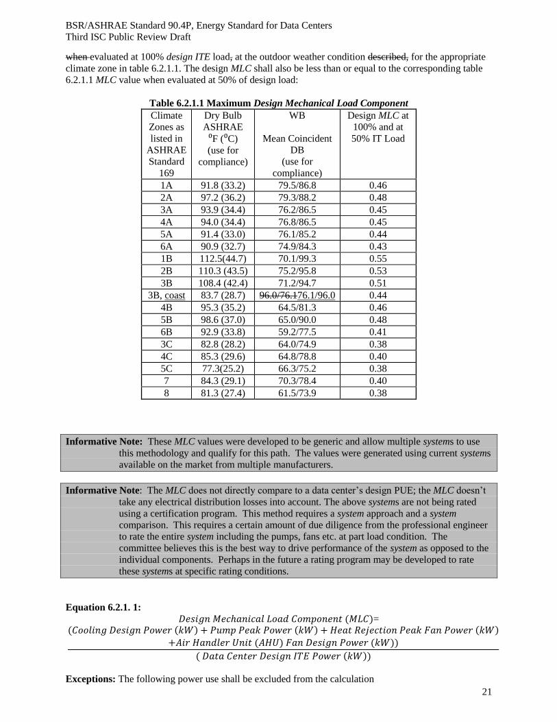
when evaluated at 100% design ITE load, at the outdoor weather condition described, for the appropriate
climate zone in table 6.2.1.1. The design MLC shall also be less than or equal to the corresponding table
6.2.1.1 MLC value when evaluated at 50% of design load:
Table 6.2.1.1 Maximum Design Mechanical Load Component
Climate
Zones as
listed in
ASHRAE
Standard
169
Dry Bulb
ASHRAE
⁰F (⁰C)
(use for
compliance)
WB
Mean Coincident
DB
(use for
compliance)
Design MLC at
100% and at
50% IT Load
1A 91.8 (33.2) 79.5/86.8 0.46
2A 97.2 (36.2) 79.3/88.2 0.48
3A 93.9 (34.4) 76.2/86.5 0.45
4A 94.0 (34.4) 76.8/86.5 0.45
5A 91.4 (33.0) 76.1/85.2 0.44
6A 90.9 (32.7) 74.9/84.3 0.43
1B 112.5(44.7) 70.1/99.3 0.55
2B 110.3 (43.5) 75.2/95.8 0.53
3B 108.4 (42.4) 71.2/94.7 0.51
3B, coast 83.7 (28.7) 96.0/76.176.1/96.0 0.44
4B 95.3 (35.2) 64.5/81.3 0.46
5B 98.6 (37.0) 65.0/90.0 0.48
6B 92.9 (33.8) 59.2/77.5 0.41
3C 82.8 (28.2) 64.0/74.9 0.38
4C 85.3 (29.6) 64.8/78.8 0.40
5C 77.3(25.2) 66.3/75.2 0.38
7 84.3 (29.1) 70.3/78.4 0.40
8 81.3 (27.4) 61.5/73.9 0.38
Informative Note: These MLC values were developed to be generic and allow multiple systems to use
this methodology and qualify for this path. The values were generated using current systems
available on the market from multiple manufacturers.
Informative Note: The MLC does not directly compare to a data center’s design PUE; the MLC doesn’t
take any electrical distribution losses into account. The above systems are not being rated
using a certification program. This method requires a system approach and a system
comparison. This requires a certain amount of due diligence from the professional engineer
to rate the entire system including the pumps, fans etc. at part load condition. The
committee believes this is the best way to drive performance of the system as opposed to the
individual components. Perhaps in the future a rating program may be developed to rate
these systems at specific rating conditions.
Equation 6.2.1. 1:
𝐷𝑒𝑠𝑖𝑔𝑛 𝑀𝑒𝑐ℎ𝑎𝑛𝑖𝑐𝑎𝑙 𝐿𝑜𝑎𝑑 𝐶𝑜𝑚𝑝𝑜𝑛𝑒𝑛𝑡 (𝑀𝐿𝐶)=
(𝐶𝑜𝑜𝑙𝑖𝑛𝑔 𝐷𝑒𝑠𝑖𝑔𝑛 𝑃𝑜𝑤𝑒𝑟 (𝑘𝑊) + 𝑃𝑢𝑚𝑝 𝑃𝑒𝑎𝑘 𝑃𝑜𝑤𝑒𝑟 (𝑘𝑊) + 𝐻𝑒𝑎𝑡 𝑅𝑒𝑗𝑒𝑐𝑡𝑖𝑜𝑛 𝑃𝑒𝑎𝑘 𝐹𝑎𝑛 𝑃𝑜𝑤𝑒𝑟 (𝑘𝑊)
+𝐴𝑖𝑟 𝐻𝑎𝑛𝑑𝑙𝑒𝑟 𝑈𝑛𝑖𝑡 (𝐴𝐻𝑈) 𝐹𝑎𝑛 𝐷𝑒𝑠𝑖𝑔𝑛 𝑃𝑜𝑤𝑒𝑟 (𝑘𝑊))
( 𝐷𝑎𝑡𝑎 𝐶𝑒𝑛𝑡𝑒𝑟 𝐷𝑒𝑠𝑖𝑔𝑛 𝐼𝑇𝐸 𝑃𝑜𝑤𝑒𝑟 (𝑘𝑊))
Exceptions: The following power use shall be excluded from the calculation
Page 22
BSR/ASHRAE Standard 90.4P, Energy Standard for Data Centers
Third ISC Public Review Draft
22
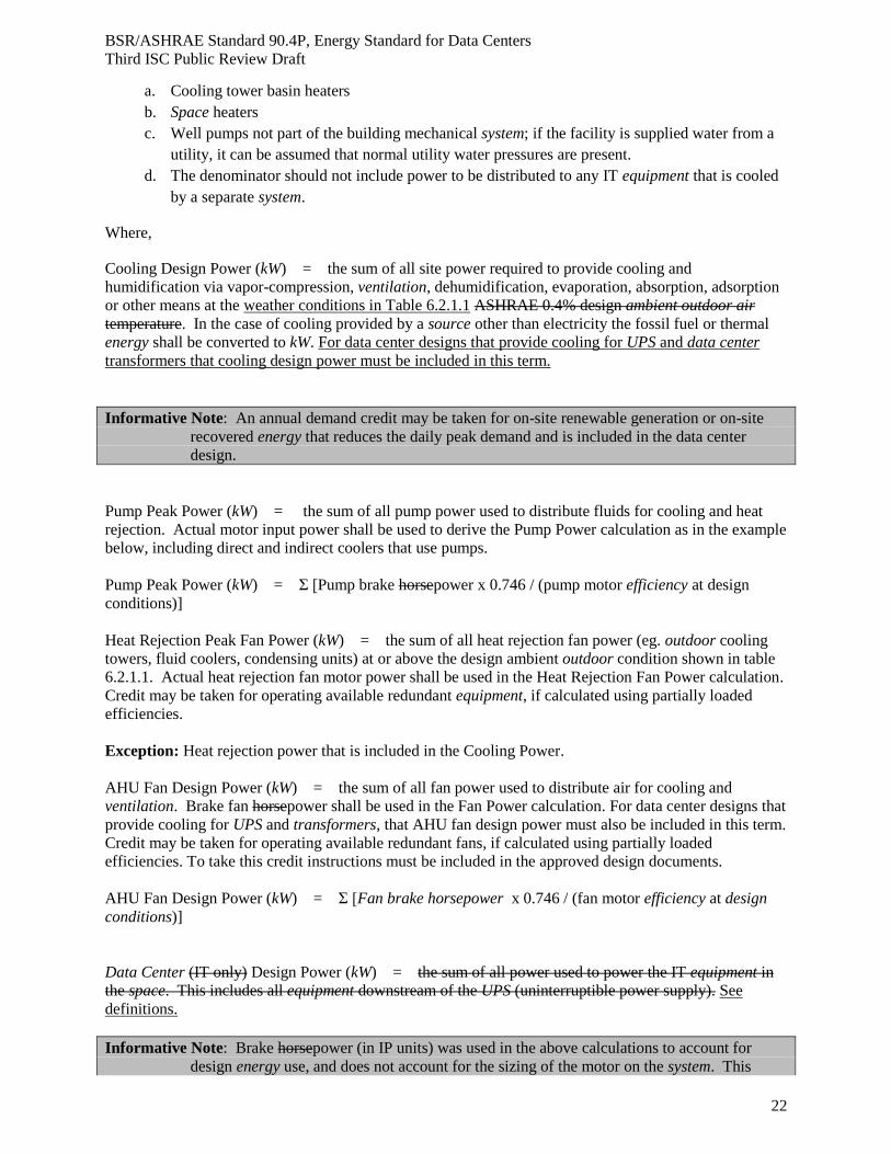
a. Cooling tower basin heaters
b. Space heaters
c. Well pumps not part of the building mechanical system; if the facility is supplied water from a
utility, it can be assumed that normal utility water pressures are present.
d. The denominator should not include power to be distributed to any IT equipment that is cooled
by a separate system.
Where,
Cooling Design Power (kW) = the sum of all site power required to provide cooling and
humidification via vapor-compression, ventilation, dehumidification, evaporation, absorption, adsorption
or other means at the weather conditions in Table 6.2.1.1 ASHRAE 0.4% design ambient outdoor air
temperature. In the case of cooling provided by a source other than electricity the fossil fuel or thermal
energy shall be converted to kW. For data center designs that provide cooling for UPS and data center
transformers that cooling design power must be included in this term.
Informative Note: An annual demand credit may be taken for on-site renewable generation or on-site
recovered energy that reduces the daily peak demand and is included in the data center
design.
Pump Peak Power (kW) = the sum of all pump power used to distribute fluids for cooling and heat
rejection. Actual motor input power shall be used to derive the Pump Power calculation as in the example
below, including direct and indirect coolers that use pumps.
Pump Peak Power (kW) = Σ [Pump brake horsepower x 0.746 / (pump motor efficiency at design
conditions)]
Heat Rejection Peak Fan Power (kW) = the sum of all heat rejection fan power (eg. outdoor cooling
towers, fluid coolers, condensing units) at or above the design ambient outdoor condition shown in table
6.2.1.1. Actual heat rejection fan motor power shall be used in the Heat Rejection Fan Power calculation.
Credit may be taken for operating available redundant equipment, if calculated using partially loaded
efficiencies.
Exception: Heat rejection power that is included in the Cooling Power.
AHU Fan Design Power (kW) = the sum of all fan power used to distribute air for cooling and
ventilation. Brake fan horsepower shall be used in the Fan Power calculation. For data center designs that
provide cooling for UPS and transformers, that AHU fan design power must also be included in this term.
Credit may be taken for operating available redundant fans, if calculated using partially loaded
efficiencies. To take this credit instructions must be included in the approved design documents.
AHU Fan Design Power (kW) = Σ [Fan brake horsepower x 0.746 / (fan motor efficiency at design
conditions)]
Data Center (IT only) Design Power (kW) = the sum of all power used to power the IT equipment in
the space. This includes all equipment downstream of the UPS (uninterruptible power supply). See
definitions.
Informative Note: Brake horsepower (in IP units) was used in the above calculations to account for
design energy use, and does not account for the sizing of the motor on the system. This
Page 23
BSR/ASHRAE Standard 90.4P, Energy Standard for Data Centers
Third ISC Public Review Draft
23
eliminates issues with a design that is close to the motor nameplate being less efficient than
a motor that is oversized compared to the nameplate.
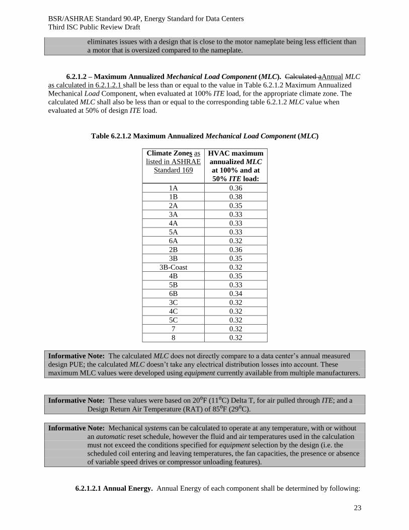
6.2.1.2 – Maximum Annualized Mechanical Load Component (MLC). Calculated aAnnual MLC
as calculated in 6.2.1.2.1 shall be less than or equal to the value in Table 6.2.1.2 Maximum Annualized
Mechanical Load Component, when evaluated at 100% ITE load, for the appropriate climate zone. The
calculated MLC shall also be less than or equal to the corresponding table 6.2.1.2 MLC value when
evaluated at 50% of design ITE load.
Table 6.2.1.2 Maximum Annualized Mechanical Load Component (MLC)
Climate Zones as
listed in ASHRAE
Standard 169
HVAC maximum
annualized MLC
at 100% and at
50% ITE load:
1A 0.36 1B 0.38
2A 0.35
3A 0.33 4A 0.33 5A 0.33 6A 0.32 2B 0.36 3B 0.35
3B-Coast 0.32 4B 0.35 5B 0.33 6B 0.34 3C 0.32 4C 0.32 5C 0.32
7 0.32 8 0.32
Informative Note: The calculated MLC does not directly compare to a data center’s annual measured
design PUE; the calculated MLC doesn’t take any electrical distribution losses into account. These
maximum MLC values were developed using equipment currently available from multiple manufacturers.
Informative Note: These values were based on 20⁰F (11⁰C) Delta T, for air pulled through ITE; and a
Design Return Air Temperature (RAT) of 85⁰F (29⁰C).
Informative Note: Mechanical systems can be calculated to operate at any temperature, with or without
an automatic reset schedule, however the fluid and air temperatures used in the calculation
must not exceed the conditions specified for equipment selection by the design (i.e. the
scheduled coil entering and leaving temperatures, the fan capacities, the presence or absence
of variable speed drives or compressor unloading features).
6.2.1.2.1 Annual Energy. Annual Energy of each component shall be determined by following:
Page 24
BSR/ASHRAE Standard 90.4P, Energy Standard for Data Centers
Third ISC Public Review Draft
24
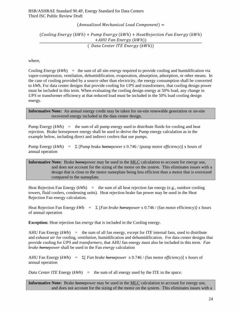
(𝐴𝑛𝑛𝑢𝑎𝑙𝑖𝑧𝑒𝑑 𝑀𝑒𝑐ℎ𝑎𝑛𝑖𝑐𝑎𝑙 𝐿𝑜𝑎𝑑 𝐶𝑜𝑚𝑝𝑜𝑛𝑒𝑛𝑡) =
(𝐶𝑜𝑜𝑙𝑖𝑛𝑔 𝐸𝑛𝑒𝑟𝑔𝑦 (𝑘𝑊ℎ) + 𝑃𝑢𝑚𝑝 𝐸𝑛𝑒𝑟𝑔𝑦 (𝑘𝑊ℎ) + 𝐻𝑒𝑎𝑡𝑅𝑒𝑗𝑒𝑐𝑡𝑖𝑜𝑛 𝐹𝑎𝑛 𝐸𝑛𝑒𝑟𝑔𝑦 (𝑘𝑊ℎ)
+𝐴𝐻𝑈 𝐹𝑎𝑛 𝐸𝑛𝑒𝑟𝑔𝑦 (𝑘𝑊ℎ))
( 𝐷𝑎𝑡𝑎 𝐶𝑒𝑛𝑡𝑒𝑟 𝐼𝑇𝐸 𝐸𝑛𝑒𝑟𝑔𝑦 (𝑘𝑊ℎ))
where,
Cooling Energy (kWh) = the sum of all site energy required to provide cooling and humidification via
vapor-compression, ventilation, dehumidification, evaporation, absorption, adsorption, or other means. In
the case of cooling provided by a source other than electricity, the energy consumption shall be converted
to kWh. For data center designs that provide cooling for UPS and transformers, that cooling design power
must be included in this term. When evaluating the cooling design energy at 50% load, any change in
UPS or transformer efficiency at that reduced load must be included in the 50% load cooling design
energy.
Informative Note: An annual energy credit may be taken for on-site renewable generation or on-site
recovered energy included in the data center design.
Pump Energy (kWh) = the sum of all pump energy used to distribute fluids for cooling and heat
rejection. Brake horsepower energy shall be used to derive the Pump energy calculation as in the
example below, including direct and indirect coolers that use pumps.
Pump Energy (kWh) = Σ [Pump brake horsepower x 0.746 / (pump motor efficiency)] x hours of
annual operation
Informative Note: Brake horsepower may be used in the MLC calculation to account for energy use,
and does not account for the sizing of the motor on the system. This eliminates issues with a
design that is close to the motor nameplate being less efficient than a motor that is oversized
compared to the nameplate.
Heat Rejection Fan Energy (kWh) = the sum of all heat rejection fan energy (e.g., outdoor cooling
towers, fluid coolers, condensing units). Heat rejection brake fan power may be used in the Heat
Rejection Fan energy calculation.
Heat Rejection Fan Energy kWh = Σ [Fan brake horsepower x 0.746 / (fan motor efficiency)] x hours
of annual operation
Exception: Heat rejection fan energy that is included in the Cooling energy.
AHU Fan Energy (kWh) = the sum of all fan energy, except for ITE internal fans, used to distribute
and exhaust air for cooling, ventilation, humidification and dehumidification. For data center designs that
provide cooling for UPS and transformers, that AHU fan energy must also be included in this term. Fan
brake horsepower shall be used in the Fan energy calculation
AHU Fan Energy (kWh) = Σ[ Fan brake horsepower x 0.746 / (fan motor efficiency)] x hours of
annual operation
Data Center ITE Energy (kWh) = the sum of all energy used by the ITE in the space.
Informative Note: Brake horsepower may be used in the MLC calculation to account for energy use,
and does not account for the sizing of the motor on the system. This eliminates issues with a
Page 25
BSR/ASHRAE Standard 90.4P, Energy Standard for Data Centers
Third ISC Public Review Draft
25
design that is close to the motor nameplate being less efficient than a motor that is oversized
compared to the nameplate.
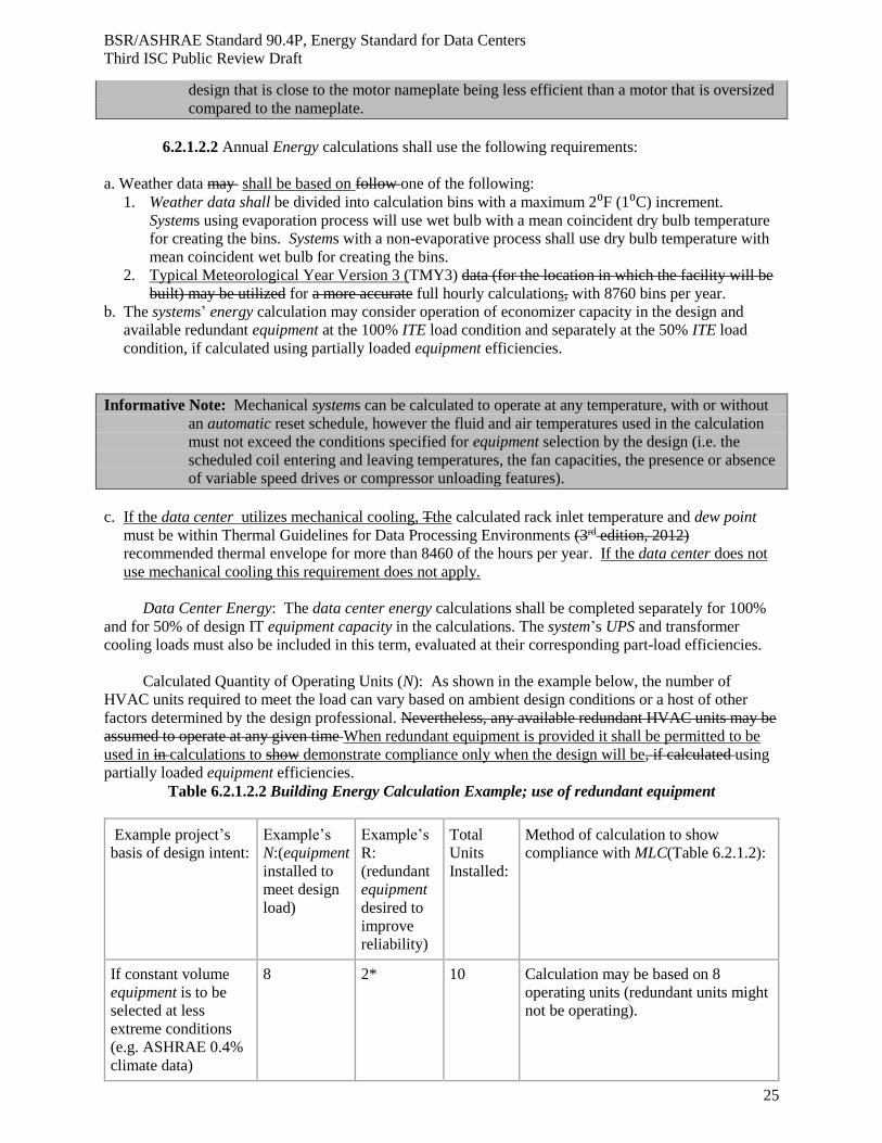
6.2.1.2.2 Annual Energy calculations shall use the following requirements:
a. Weather data may shall be based on follow one of the following:
1. Weather data shall be divided into calculation bins with a maximum 2⁰F (1⁰C) increment.
Systems using evaporation process will use wet bulb with a mean coincident dry bulb temperature
for creating the bins. Systems with a non-evaporative process shall use dry bulb temperature with
mean coincident wet bulb for creating the bins.
2. Typical Meteorological Year Version 3 (TMY3) data (for the location in which the facility will be
built) may be utilized for a more accurate full hourly calculations, with 8760 bins per year.
b. The systems’ energy calculation may consider operation of economizer capacity in the design and
available redundant equipment at the 100% ITE load condition and separately at the 50% ITE load
condition, if calculated using partially loaded equipment efficiencies.
Informative Note: Mechanical systems can be calculated to operate at any temperature, with or without
an automatic reset schedule, however the fluid and air temperatures used in the calculation
must not exceed the conditions specified for equipment selection by the design (i.e. the
scheduled coil entering and leaving temperatures, the fan capacities, the presence or absence
of variable speed drives or compressor unloading features).
c. If the data center utilizes mechanical cooling, Tthe calculated rack inlet temperature and dew point
must be within Thermal Guidelines for Data Processing Environments (3rd edition, 2012)
recommended thermal envelope for more than 8460 of the hours per year. If the data center does not
use mechanical cooling this requirement does not apply.
Data Center Energy: The data center energy calculations shall be completed separately for 100%
and for 50% of design IT equipment capacity in the calculations. The system’s UPS and transformer
cooling loads must also be included in this term, evaluated at their corresponding part-load efficiencies.
Calculated Quantity of Operating Units (N): As shown in the example below, the number of
HVAC units required to meet the load can vary based on ambient design conditions or a host of other
factors determined by the design professional. Nevertheless, any available redundant HVAC units may be
assumed to operate at any given time When redundant equipment is provided it shall be permitted to be
used in in calculations to show demonstrate compliance only when the design will be, if calculated using
partially loaded equipment efficiencies.
Table 6.2.1.2.2 Building Energy Calculation Example; use of redundant equipment
Example project’s
basis of design intent: Example’s
N:(equipment
installed to
meet design
load)
Example’s
R:
(redundant
equipment
desired to
improve
reliability)
Total
Units
Installed:
Method of calculation to show
compliance with MLC(Table 6.2.1.2):
If constant volume
equipment is to be
selected at less
extreme conditions
(e.g. ASHRAE 0.4%
climate data)
8 2* 10 Calculation may be based on 8
operating units (redundant units might
not be operating).
Page 26
BSR/ASHRAE Standard 90.4P, Energy Standard for Data Centers
Third ISC Public Review Draft
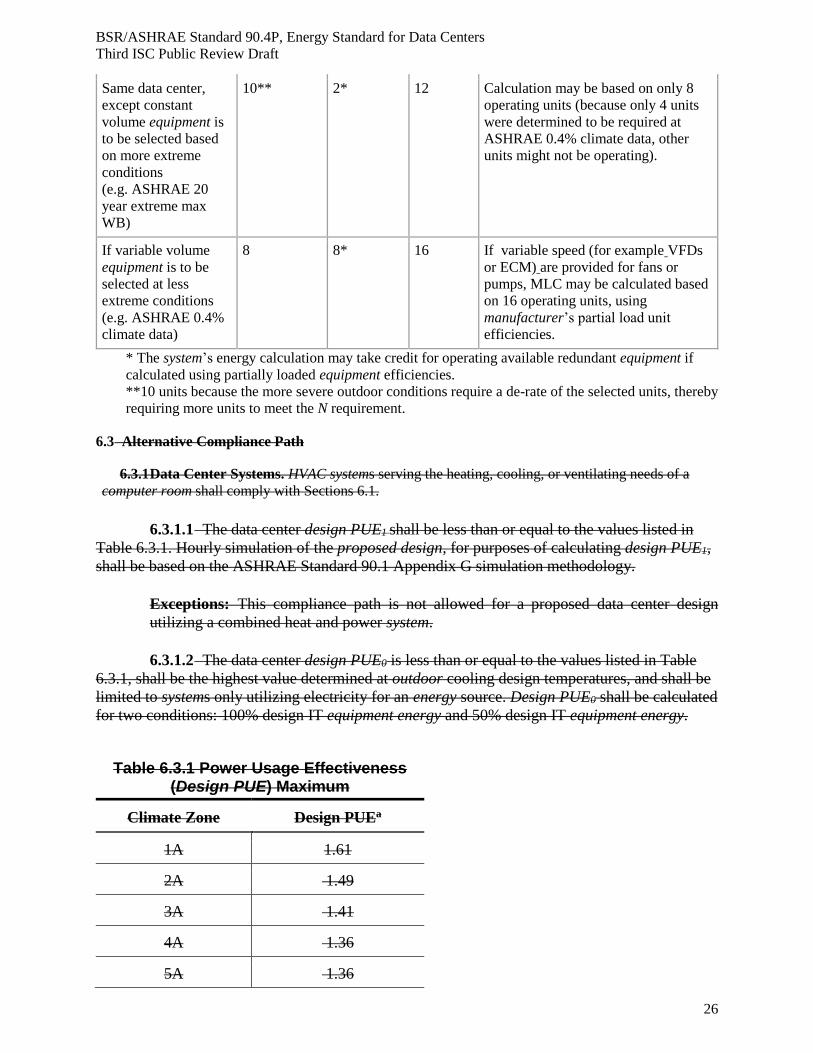
26
Same data center,
except constant
volume equipment is
to be selected based
on more extreme
conditions
(e.g. ASHRAE 20
year extreme max
WB)
10** 2* 12 Calculation may be based on only 8
operating units (because only 4 units
were determined to be required at
ASHRAE 0.4% climate data, other
units might not be operating).
If variable volume
equipment is to be
selected at less
extreme conditions
(e.g. ASHRAE 0.4%
climate data)
8 8* 16 If variable speed (for example VFDs
or ECM) are provided for fans or
pumps, MLC may be calculated based
on 16 operating units, using
manufacturer’s partial load unit
efficiencies.
* The system’s energy calculation may take credit for operating available redundant equipment if
calculated using partially loaded equipment efficiencies.
**10 units because the more severe outdoor conditions require a de-rate of the selected units, thereby
requiring more units to meet the N requirement.
6.3 Alternative Compliance Path
6.3.1 Data Center Systems. HVAC systems serving the heating, cooling, or ventilating needs of a
computer room shall comply with Sections 6.1.
6.3.1.1 The data center design PUE1 shall be less than or equal to the values listed in
Table 6.3.1. Hourly simulation of the proposed design, for purposes of calculating design PUE1,
shall be based on the ASHRAE Standard 90.1 Appendix G simulation methodology.
Exceptions: This compliance path is not allowed for a proposed data center design
utilizing a combined heat and power system.
6.3.1.2 The data center design PUE0 is less than or equal to the values listed in Table
6.3.1, shall be the highest value determined at outdoor cooling design temperatures, and shall be
limited to systems only utilizing electricity for an energy source. Design PUE0 shall be calculated
for two conditions: 100% design IT equipment energy and 50% design IT equipment energy.
Table 6.3.1 Power Usage Effectiveness (Design PUE) Maximum
Climate Zone Design PUEa
1A 1.61
2A 1.49
3A 1.41
4A 1.36
5A 1.36
Page 27
BSR/ASHRAE Standard 90.4P, Energy Standard for Data Centers
Third ISC Public Review Draft
27
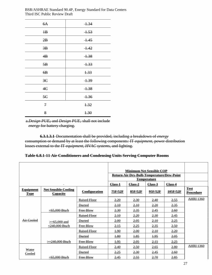
6.3.1.3.1 Documentation shall be provided, including a breakdown of energy
consumption or demand by at least the following components: IT equipment, power distribution
losses external to the IT equipment, HVAC systems, and lighting.
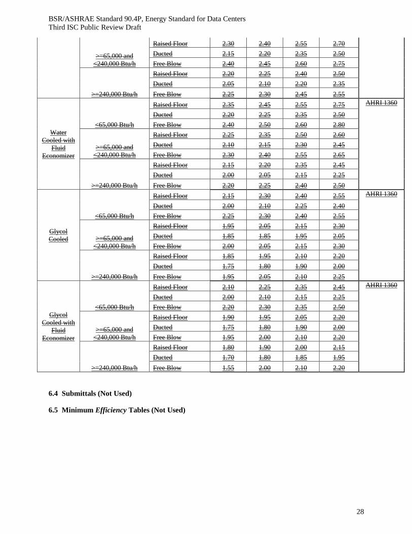
Table 6.8.1-11 Air Conditioners and Condensing Units Serving Computer Rooms
Minimum Net Sensible COP
Return Air Dry-Bulb Temperature/Dew-Point
Temperature
Class 1 Class 2 Class 3 Class 4
Equipment
Type
Net Sensible Cooling
Capacity Configuration 75F/52F 85F/52F 95F/52F 105F/52F
Test
Procedure
Air Cooled
<65,000 Btu/h
Raised Floor 2.20 2.30 2.40 2.55 AHRI 1360
Ducted 2.10 2.10 2.20 2.35
Free Blow 2.30 2.35 2.45 2.60
>=65,000 and
<240,000 Btu/h
Raised Floor 2.10 2.20 2.30 2.45
Ducted 2.00 2.05 2.10 2.25
Free Blow 2.15 2.25 2.35 2.50
>=240,000 Btu/h
Raised Floor 1.90 2.00 2.10 2.20
Ducted 1.80 1.85 1.95 2.05
Free Blow 1.95 2.05 2.15 2.25
Water
Cooled <65,000 Btu/h
Raised Floor 2.40 2.50 2.65 2.80 AHRI 1360
Ducted 2.25 2.30 2.45 2.60
Free Blow 2.45 2.55 2.70 2.85
6A 1.34
1B 1.53
2B 1.45
3B 1.42
4B 1.38
5B 1.33
6B 1.33
3C 1.39
4C 1.38
5C 1.36
7 1.32
8 1.30
a. Design PUE0 and Design PUE1 shall not include
energy for battery charging.
Page 28
BSR/ASHRAE Standard 90.4P, Energy Standard for Data Centers
Third ISC Public Review Draft
28
>=65,000 and
<240,000 Btu/h
Raised Floor 2.30 2.40 2.55 2.70
Ducted 2.15 2.20 2.35 2.50
Free Blow 2.40 2.45 2.60 2.75
>=240,000 Btu/h
Raised Floor 2.20 2.25 2.40 2.50
Ducted 2.05 2.10 2.20 2.35
Free Blow 2.25 2.30 2.45 2.55
Water
Cooled with
Fluid
Economizer
<65,000 Btu/h
Raised Floor 2.35 2.45 2.55 2.75 AHRI 1360
Ducted 2.20 2.25 2.35 2.50
Free Blow 2.40 2.50 2.60 2.80
>=65,000 and
<240,000 Btu/h
Raised Floor 2.25 2.35 2.50 2.60
Ducted 2.10 2.15 2.30 2.45
Free Blow 2.30 2.40 2.55 2.65
>=240,000 Btu/h
Raised Floor 2.15 2.20 2.35 2.45
Ducted 2.00 2.05 2.15 2.25
Free Blow 2.20 2.25 2.40 2.50
Glycol
Cooled
<65,000 Btu/h
Raised Floor 2.15 2.30 2.40 2.55 AHRI 1360
Ducted 2.00 2.10 2.25 2.40
Free Blow 2.25 2.30 2.40 2.55
>=65,000 and
<240,000 Btu/h
Raised Floor 1.95 2.05 2.15 2.30
Ducted 1.85 1.85 1.95 2.05
Free Blow 2.00 2.05 2.15 2.30
>=240,000 Btu/h
Raised Floor 1.85 1.95 2.10 2.20
Ducted 1.75 1.80 1.90 2.00
Free Blow 1.95 2.05 2.10 2.25
Glycol
Cooled with
Fluid
Economizer
<65,000 Btu/h
Raised Floor 2.10 2.25 2.35 2.45 AHRI 1360
Ducted 2.00 2.10 2.15 2.25
Free Blow 2.20 2.30 2.35 2.50
>=65,000 and
<240,000 Btu/h
Raised Floor 1.90 1.95 2.05 2.20
Ducted 1.75 1.80 1.90 2.00
Free Blow 1.95 2.00 2.10 2.20
>=240,000 Btu/h
Raised Floor 1.80 1.90 2.00 2.15
Ducted 1.70 1.80 1.85 1.95
Free Blow 1.55 2.00 2.10 2.20
6.4 Submittals (Not Used)
6.5 Minimum Efficiency Tables (Not Used)
Page 29
BSR/ASHRAE Standard 90.4P, Energy Standard for Data Centers
Third ISC Public Review Draft
29
7. SERVICE WATER HEATING
7.1 General. Provisions of this section shall comply with provisions of Section 7.1 of
ANSI/ASHRAE/IES Standard 90.1.
7.2 Definition of Compliance Paths. Provisions of this section shall comply with provisions of Section
7 of ANSI/ASHRAE/IES Standard 90.1 or demonstrate energy efficiency improvement compared to a data
center designed to comply with Section 7 of ANSI/ASHRAE/IES Standard 90.1.
Page 30
BSR/ASHRAE Standard 90.4P, Energy Standard for Data Centers
Third ISC Public Review Draft
30
8. ELECTRICAL
8.1 General
8.1.1 Scope. This section applies to the building electrical systems delivering power to the data center
IT load, and to equipment described below. Refer to Figure 8.1.
8.2 Definition of Compliance Paths. Compliance with Section 8 shall be achieved by meeting all
requirements in Section 8.1, General; and Section 8.2.1, Electrical systems.
8.2.1 Electrical systems. Electrical systems shall comply with Section 8.2.1.1. ITE power is not assumed
to be seasonably variable in this standard. Therefore ITE energy can be calculated by multiplying ITE
power by 8,760, the number of hours in a normal year. The data center design ITE power must be
specified on the construction documents.
8.2.1.1 Maximum Design Electrical Loss Component (ELC) for Designs Involving Electrical
Systems Only. Design ELC shall be calculated in accordance with Section 8.3 and shall be less than or
equal to the values shown in Table 8.2.1.1.
8.2.1.2 Maximum Design Electrical Loss Component (ELC) for designs involving both electrical
and mechanical systems. Design ELC shall be calculated in accordance with Section 8.3 and shall be
combined with the Mechanical Loss Component (MLC) in accordance with Section 11.
Informative Note: ELC numbers less than or equal to the values in Tables 8.2.1.1 or 8.2.1.2 combined
with the MLC numbers less than or equal to the appropriate values in Chapter 6, will assure
compliance with this standard.
8.2.1.1.1 Design ELC for New Designs or Total Renovations. Tradeoffs are allowed among the
three segments to achieve the ELC values shown. (See Informative C.5 Examples - Design ELC
Calculations)
8.2.1.1.2 Design ELC for Partial Renovations. For a facility being renovated where only one or
two of the three EEC segments are being modified, compliance requirements apply only to the segment(s)
being modified. Tradeoffs are allowed between segments being modified to meet the aggregate
requirement of those segments.
Informative Note: See Appendix C.5 Examples = Design ELC Calculations for methods of combining
ELC segment values.
Table 8.2.1.1 Minimum Maximum Design Electrical Loss Component (Less Than 100 kW kVA IT
Design Load)
Compliance Path
Design Electrical Loss
Component
Informative Note for Reviewers: See informative appendix C for additional trade-offs
Page 31
BSR/ASHRAE Standard 90.4P, Energy Standard for Data Centers
Third ISC Public Review Draft
31
ASHRAE 90.4P – Design Electrical Loss Component (ELC) and ELC Segments
Systems with IT Design Load Less Than 100 kVAkW
UPS Redundancy Configuration
Single Feed UPS
(N, N+1, etc.) or No UPS
See Informative Note A
Active Dual Feed UPS
(2N, 2N+1, etc.)
See Informative Note B
Calculation Percentage
100% of
IT Design Load
Segment ELC
50% of
IT Design Load
Segment ELC
50% of
IT Design Load
Segment ELC
25% of
IT Design Load
Segment ELC
Segments of Electrical Loss
Component and Overall ELC Loss / Efficiency Loss / Efficiency Loss / Efficiency Loss / Efficiency
Incoming Service Segment 15.0%/85.0% 11.0%/89.0% 11.0%/89.0% 10.0%/90.0%
UPS Segment 12.0%/88.0% 14.0%/86.0% 14.0%/86.0% 20.0%/80.0%
ITE Distribution Segment 6.0%/94.0% 4.0%/96.0% 4.0%/96.0% 3.0%/97.0%
Electrical Loss / Efficiency Total 11.6% / 88.4%
29.7%/70.3%
12.6% / 87.4%
26.5%/73.5%
12.6% / 87.4%
26.5%/73.5%
13.5% / 86.5%
30.2%/69.8%
Electrical Loss Component
(ELC)
0.116
0.297
0.126
0.265
0.126
0.265
0.135
0.302
Table 8.2.1.2 MinimumMaximum Design Electrical Loss Component (100 kVA kW or Greater IT
Design Load)
ASHRAE 90.4P - Electrical Loss Component (ELC) and ELC Segments
Systems with IT Design Load of 100 kVA kW or Greater
UPS Redundancy Configuration
Single Feed UPS
(N, N+1, etc.) or No UPS
See Informative Note A
Active Dual Feed UPS
(2N, 2N+1, etc.)
See Informative Note B
Calculation Percentage
100% of
IT Design Load
Segment ELC
50% of
IT Design Load
Segment ELC
50% of
IT Design Load
Segment ELC
25% of
IT Design Load
Segment ELC
Segments of Electrical Loss
Component and Overall ELC Loss / Efficiency Loss / Efficiency Loss / Efficiency Loss / Efficiency
Incoming Service Segment 15.0%/85.0% 11.0%/89.0% 11.0%/89.0% 10.0%/90.0%
UPS Segment 9.0%/91.0% 10.0%/90.0% 10.0%/90.0% 15.0%/85.0%
ITE Distribution System 5.0%/95.0% 4.0%/96.0 % 4.0%/96.0% 3.0%/97.0%
Electrical Loss / Efficiency Total* 10.2% / 89.8%
26.5%/73.5%
11.4% / 88.6%
23.1%/76.9%
11.4% / 88.6%
23/1%/76.9%
11.9% / 88.1%
25.8%/74.2%
Electrical Loss Component
(ELC)
0.102
0.265
0.114
0.231
0.114
0.231
0.119
0.258 *Example calculations shown in Informative Appendix C
Informative Note A: These columns in Tables 8.2.1.1 and 8.2.1.2 apply to electrical configurations
resulting in a single output feed from the UPS, irrespective of the number of UPS modules
that are may be paralleled prior to the output feed, or the number of branches or sub-feeders
into which that output feeder may be divided.
Page 32
BSR/ASHRAE Standard 90.4P, Energy Standard for Data Centers
Third ISC Public Review Draft
32
Informative Note B: These columns in Tables 8.2.1.1and 8.2.1.2 apply to electrical configurations made
up of two distinct and electrically separated UPS systems resulting in two distinct and
electrically separate output feeds, either of which is capable of independently supporting the
total design load. Systems that meet these criteria may be made up of any number of UPS
modules that are paralleled prior to each output feed. Cross-ties and/or transfer switches
downstream of the independent feeds shall not continually tie the two output sections
together.
8.2.2 Electrical Distribution Systems. Provisions of this section shall comply either with provisions
of Section 8 of ANSI/ASHRAE/IES Standard 90.1 or with Section 8.3 below.
8.3 Compliance Path
8.3.1 Electrical Distribution Systems for Mechanical Loads. The electrical distribution systems
serving mechanical loads shall be designed with pathway losses not exceeding 2%; however, these losses
shall not be incorporated into the Design ELC calculations set forth in this Section 8.0.
8.3.1.1 Where there are multiple paths for any segment of the electrical distribution system, the
calculations shall use the paths with the highest losses and/or lowest efficiencies for each segment to
demonstrate compliance.
8.3.1.2 The Design ELC calculations shall use the minimum operating efficiency or maximum
operating loss of each component, unless a specific mode of operation (with higher efficiency or lower
loss) is designated on the approved design documents.
8.3.1.3 It shall be permissible to apply corrections for losses and/or efficiencies of each component
and/or segment for actual conditions to the extent those conditions can be demonstrated and such
adjustments are in compliance with applicable codes and ordinances. (e.g., Conductor resistance
correction as a function of actual operating temperature.)
8.3.1.4 Incoming Service Segment. A segment loss value shall be calculated for the incoming service
segment of the design electrical loss component. This value shall be based on all equipment efficiencies
and resulting losses in this segment at the design load for all downstream equipment served.
Exception: Emergency or stand-by power systems are not considered a part of the incoming service
segment, with the exception of individual elements such as associated transfer switches,
transformers or other devices that are also included between the design ELC demarcation and the
UPS
8.3.1.5 UPS Segment Efficiency. Efficiency and resulting loss through the UPS segment shall be
calculated at both full and partial loads, depending on configuration, as follows:
a. For “N” or , “N+1” or “N+n” UPS configurations, losses shall be based on manufacturer’s stated
efficiencies at 100% and 50% of the UPS operational design load
b. For “2N”, “2N+1”, 2(N+1) or other Dual Feed UPS configurations, the systems are each intended to
normally operate at no more than half capacity. Therefore the UPS losses shall be based on
manufacturer’s stated efficiencies at 50% and 25% of the UPS operational design load. Where UPS
systems are identical, only one of the systems shall be used in the calculation. Where UPS systems
are not identical, both systems shall be calculated and the system with the lowest efficiency shall be
used to compute the UPS segment of the Electrical Loss Component.
c. Where UPS’s have more than one mode of operation (e.g. normal and UPS economy modes), the
mode used in these calculations shall be the same as the mode used as the basis of design and so-
designated on the approved construction documents.
Page 33
BSR/ASHRAE Standard 90.4P, Energy Standard for Data Centers
Third ISC Public Review Draft
33
d. Where non-rated UPS systems are utilized the efficiencies and losses shall be as published or
provided in writing by the manufacturer.
8.3.1.6 ITE Distribution Segment Efficiency. Where significant numbers of power paths exist
between the UPS and the many equipment cabinets, the ITE distribution segment efficiency shall be that
with the lowest path efficiency. This shall be the longest path with the largest numbers of loss producing
components such as transformers, switchgear and/or panelboards. Calculations are required to determine
the path with the greatest loss or lowest efficiency, which shall be used in developing the total Electrical
Loss Component.
8.3.1.7 Combined UPS and Pathway Loss Calculations. The design electrical loss component
(ELC) shall be calculated as the product of the calculated Pre-UPS Incoming Service Segment loss, the
UPS segment loss, and the ITE distribution segment loss.
Informative Note: See Appendix C.5, Examples Design ELC Calculations, for methods of combining
ELC Segment Values.
8.3.1.8 Alternate Designs. In the event a UPS is not used in the design, the incoming and
distribution segments shall meet at the point(s) where a UPS would logically be inserted. Where another
device is used in place of the UPS, such as a rectifier, voltage regulator or harmonic neutralizing
transformer, the efficiency and loss for that device shall be used in the efficiency calculation in the same
manner as defined for a UPS.
8.3.1.9 Derivation of Electrical Component Efficiencies. Compliance shall be demonstrated by
the following:
a. Rated Equipment The efficiency values used in the calculations, or the loss numbers used in
equivalent efficiency calculations, shall be the manufacturer’s numbers as derived from the
standardized testing, and shall be based on the design ITE load.
b. Unrated Equipment – Where no testing and rating standards exist for an electrical component the
efficiency values or loss shall be as published by, or as stated in writing by, the component
manufacturer.
c. Wiring and cable – the efficiency or loss shall be calculated per the applicable electrical code.
8.3.2 Power Compliance Path. See informative reference C.5 for an illustrative diagram of the power
compliance path.
8.4 Submittals
8.4.1 Drawings. Construction documents shall require that within 30 days a time determined by the
building owner and the contractor(s) after the date of system acceptance, record drawings of the actual
installation shall be provided to the building owner, including
a. a single-line diagram of the building electrical distribution system,
b. floor plans indicating locations of and areas served by all distribution,
c. all conditions used for the basis of design and calculations such as UPS n+1, UPS economy mode
operation, and
d. Electrical Loss Component calculations showing the actual numbers used and demonstrating
compliance with the applicable Table 8.2.1.1 values.
Page 34
BSR/ASHRAE Standard 90.4P, Energy Standard for Data Centers
Third ISC Public Review Draft
34
8.4.2 Manuals. Construction documents shall require that an operating manual and maintenance
manual be provided to the building owner. The manuals shall include, at a minimum, the following:
a. Submittal data stating equipment rating and selected options for each piece of equipment requiring
maintenance.
b. Operation and maintenance manuals for each piece of equipment requiring maintenance. Required
routine maintenance actions shall be clearly identified.
c. Names and addresses of at least one qualified service agency.
d. A complete narrative of how each system is intended to operate.
Page 35
BSR/ASHRAE Standard 90.4P, Energy Standard for Data Centers
Third ISC Public Review Draft
35
9. LIGHTING
9.1 General
9.1.1 Scope. This section shall apply to interior equipment spaces of data centers.
9.2 Definition of Compliance Paths
Lighting Systems. Lighting systems and equipment shall comply with Section 9 of
ANSI/ASHRAE/IES Standard 90.1
Page 36
BSR/ASHRAE Standard 90.4P, Energy Standard for Data Centers
Third ISC Public Review Draft
36
10. OTHER EQUIPMENT
10.1 General. Provisions of this section shall comply with Section 10 of ANSI/ASHRAE/IES Standard
90.1.
Informative Note: This standard is intended to provide a fair method of comparison between
the estimated annual energy of the proposed design and a base design for purposes of
compliance with the Standard. It is not intended to provide the most accurate prediction of
actual energy consumption or other utilities and costs for the building as it is actually built or as
it relates to other buildings. Site energy and related metrics can be measured and verified,
where the facility designers (and building owners or designees) have the most control and
provides an incentive at the building level of preferred items. In addition to focusing on these
site energy uses, this standard also does not evaluate overall use of related utilities such as
water, including site harvested or source water provided from the local utility. Both can play a
part in the overall energy use of the facility, in addition to the overall water use of the facility
and its effect on the region. While these are important items to consider, including the efficient
use of water, they are outside the scope and purpose of this document.
Page 37
BSR/ASHRAE Standard 90.4P, Energy Standard for Data Centers
Third ISC Public Review Draft
37
11. GUIDE TO ALTERNATIVE COMPLIANCE METHOD
11.1 General. Provisions of this Standard require the user to demonstrate compliance with provisions of
Sections 5 through Section 9.
The complete submittal data requirements that the user must complete and provide to the AHJ as required
for the specific project and outlined in section 4.
Informative Note: See the table in the Informative Appendix C for a sample submittal form.
11.1.1 Section 6 and 8 Trade-Off Method Scope. The Chapter 6 and 8 Trade-Off Method is an
alternative to individually demonstrating compliance with Chapter 6 and Chapter 8 requirements. It shall
be allowed for demonstrating compliance when evaluating the proposed designs when either the Design
MLC or Design ELC is greater than the maximum allowed by the standard.
11.1.2 Section 6 and 8 Trade-Off Method Rationale. A design that has various physical or other types
of constraints shall be allowed flexibility to demonstrate compliance with this standard. These constraints
may impact the mechanical or electrical design. This trade-off method allows a less efficient electrical
system to be off-set by a more efficient mechanical system of visa-versa in order to demonstrate
compliance.
11.2 Chapter 6 and 8 Trade-off Method
11.2.1 Compliance. Compliance with Section 11 is demonstrated if
a. all requirements of Sections 5, 7, 9, and 10 are met;
b. The sum of the The required Design MLC value and the Design ELC value create a Design overall
systems value. The calculated values of the proposed Design MLC and Design ELC values summed
shall be equal to or less than the Max Overall systems value. in for the mechanical and electrical system
may be summed to create an overall systems value. Compliance may be achieved if the calculated values
of the proposed mechanical and electrical systems summed are equal to or less than the required summed
values. (See Informative Appendix C.2 for an illustrative flow chart.)
Informative Note: See below for examples of demonstrating compliance with the Trade-Off Method.
For a particular design in Climate Zone 1A with a single feed UPS at 100% load, the Max MLC= .46
from Table 6.2.1.1 and the Max ELC .116 from Table 8.2.1.1. Adding the two values together provides a
Max overall systems value of 0.576.
Max MLC Value 0.46
+Max ELC Value +0.297
=Data Center Target Value =0.757
If the electrical system design produces a Design ELC of .14 which exceeds the Max ELC value, a more
efficient mechanical system can be used to off-set this. If the mechanical system had a Design MCL of
0.39, then the overall systems design value would be less than the Max overall systems value and would
demonstrate compliance with the standard.
-
Design MLC Value 0.39
+Design ELC Value +0.21
Page 38
BSR/ASHRAE Standard 90.4P, Energy Standard for Data Centers
Third ISC Public Review Draft
38
=Data Center Proposed Value =0.60
Informative note: See Informative Appendix C.2 for guidance on complying with the standard and for
use of the trade-off method.
11.3 Use of Shared Systems. When existing or proposed mechanical and/or electrical systems are
intended to be routinely support the data center and other spaces (spaces that may or may not meet the
definition of a data center), the data center or data center addition may document its compliance using the
annualized energy performance method (as described in Chapters 6.2.1.2 and 8.3). The shared systems’
future total hourly loads must be determined for a typical year (using TMY3 weather data) to determine
what fraction of the total shared systems’ capacity (for each hour of the typical year) will be utilized by
the data center addition. The total shared system input energy is multiplied by the data center addition’s
fraction of total system capacity, for each hour, to determine the data center addition’s input energy used
to show compliance. In the case where other spaces sharing systems with the data center are within the
scope of ASHRAE Standard 90.1, the Energy Cost Budget Method described in Chapter 11 of Standard
90.1 may be followed to determine (for compliance’s sake) the hour-by-hour fraction of the shared
system’s capacity that is utilized by the non-data center spaces.
Informative Note: Shared mechanical systems serving data centers and other spaces (within the scope of
Standard 90.1) may or may not be required to provide economizer savings to the non-data center spaces.
Standard 90.4 will not affect that requirement, nor require that economizer capacity be provided for the
portion of a shared system serving a data center or data center addition that otherwise meets 90.4 annual
energy performance targets when calculated as described above.
Informative Note: Recovered heat from a data center that routinely shares a mechanical system with non-
data center spaces can reduce the energy use of non-data center spaces which are designed to accept the
recovered heat. If the heat required by the non-data center spaces is significant, such a relationship can
provide energy savings far beyond the savings which would be brought by applying an economizer to the
data center addition.
Page 39
BSR/ASHRAE Standard 90.4P, Energy Standard for Data Centers
Third ISC Public Review Draft
39
Page 40
BSR/ASHRAE Standard 90.4P, Energy Standard for Data Centers
Third ISC Public Review Draft
40
12. NORMATIVE REFERENCES
Section numbers indicate where the reference occurs in this document.
Reference Title
Air-Conditioning Heating and Refrigeration Institute (AHRI)
2111 Wilson Boulevard, Suite 500
Arlington, VA 22201, United States
BTS 2000 Testing Standard Method to Determine Efficiency of Commercial Space Heating Boilers
AHRI 1160-2008 Performance Rating of Heat Pump Pool Heaters
AHRI 210/240-2008 Unitary Air Conditioning and Air-Source Heat Pump Equipment
AHRI 340/360-2007 Performance Rating of Commercial and Industrial Unitary Air-Conditioning and Heat Pump Equipment
AHRI 310/380-2004 Package Terminal Air-Conditioners and Heat Pumps
AHRI 365-2009 Commercial and Industrial Unitary Air-Conditioning Condensing Units
AHRI 390-2003 Performance Rating of Single Packaged Vertical Air-Conditioners and Heat Pumps
AHRI 400-2001 Performance Rating of Liquid to Liquid Heat Exchangers
AHRI 460-2005 Remote Mechanical Draft Air Cooled Refrigerant Condensers
AHRI 550/590-2003 Performance Rating of Water-Chilling Packages Using the Vapor Compression Cycle
AHRI 560-2000 Absorption Water Chilling and Water Heating Packages
AHRI 1230-2010 Performance Rating of Variable Refrigerant Flow (VRF) Multi-split Air-Conditioning and Heat Pump Equipment
ANSI/AHRI 1360-2013 Performance Rating of Computer and Data Processing Room Air Conditioners
Air Movement and Control Association International
30 West University Drive
Arlington Heights, IL 60004-1806, United States
AMCA 500-D-0712 Laboratory Method of Testing Dampers for Rating
American National Standards Institute (ANSI)
11 West 42nd Street
Page 41
BSR/ASHRAE Standard 90.4P, Energy Standard for Data Centers
Third ISC Public Review Draft
41
New York, NY 10036, United States
ANSI Z21.10.3-2004 Gas Water Heater, Volume 3, Storage, with Input Ratings above 75,000 Btu/h
ANSI Z21.47-2006 Gas-Fired Central Furnaces (Except Direct Vent and Separated Combustion System Furnaces)
ANSI 83.8-2009 Gas Unit Heaters and Duct Furnaces
American Society of Heating, Refrigerating and Air-Conditioning Engineers (ASHRAE)
1791 Tullie Circle NE
Atlanta, GA 30329, United States
1-404-636-8400; www.ashrae.org
ANSI/ASHRAE Standard 55-2010 Thermal Comfort Conditions for Human Occupancy
ANSI/ASHRAE Standard 62.1-2013 Ventilation for Acceptable Indoor Air Quality
ANSI/ASHRAE/IES Standard 90.1-20102013 Energy Standard for Buildings Except Low-Rise Residential Buildings
ANSI/ASHRAE Standard 140-2004 Standard Method of Test for the Evaluation of Building Energy Analysis Computer Programs
ANSI/ASHRAE Standard 127-2012 Method of Testing for Rating Computer and data Processing Room Unitary Air Conditioners
ANSI/ASHRAE Standard 169-2013 Climatic Data for Building Design Standards
Briggs, R.S., R.G. Lucas, and Z.T. Taylor. 2003. Climate classification for building energy codes and standards Part 1 –
Thermal Guidelines for Data Processing Environments (3rd edition, 2012)
Association of Home Appliance Manufacturers
1111 19th St. NW, Suite 402
Washington DC 20036, United States
ANSI/AHAM RAC-1-R2008 Room Air Conditioners
American Society of Civil Engineers (ASCE)
1801 Alexander Bell Drive
Reston, VA 20191
Page 42
BSR/ASHRAE Standard 90.4P, Energy Standard for Data Centers
Third ISC Public Review Draft
42
ASCE 7-10/IBC Seismic Design Provisions of the Standard Minimum Design Loads for Buildings and Other Structures
BSI Group
389 Chiswick High Road
London
W4 4AL
United Kingdom
BS EN50082-1:1998 Electromagnetic compatibility. Generic immunity standard. Residential, commercial and light industry
BS EN 50091-1:1993 Specification General and Safety Requirements for uninterruptible power systems (UPS). EMC requirements
BS EN 50091-2:1996 Specification for uninterruptible power systems (UPS). EMC requirements
BS EN 50091-3:1999 Specification for uninterruptible power systems (UPS). EMC requirements
BS EN 61000-6-3:2007 Electromagnetic Compatibility (EMC). Generic standards. Emission standard for residential, commercial and light-
industrial environments
BS EN 61000-6-2:2005 Electromagnetic compatibility (EMC). Generic standards. Immunity for industrial environments
BS EN 60947-6-1:2005 Low-voltage switchgear and controlgear. Multiple function equipment. Transfer switching equipment
Canadian Standards Association (CSA)
178 Rexdale Blvd.
Toronto, ON
Canada M9W 1R3
C22.2 NO. 31-14 Switchgear Assemblies
Cooling Technology Institute
2611 FM 1960 West, Suite A-101
Houston, TX 77068-3730, United States
CTI ATC-105 (00) Acceptance Test Code for Water Cooling Towers
CTI ATC-105S (96) Acceptance Test Code for Closed-Circuit Cooling Towers
CTI STD-201 (09) Standard for Thermal Performance Certification of Evaporative Heat Transfer Equipment
Page 43
BSR/ASHRAE Standard 90.4P, Energy Standard for Data Centers
Third ISC Public Review Draft
43
Federal Communications Commission
445 12th Street, SW
Washington, DC 20554
CFR FCC Title 47 Part 15 Radio Frequency Devices
CTI ATC-105S (96) Acceptance Test Code for Closed-Circuit Cooling Towers
CTI STD-201 (09) Standard for Thermal Performance Certification of Evaporative Heat Transfer Equipment
International Electrotechnical Commission
3, rue de Varembé
P.O. Box 131
CH - 1211 Geneva 20 - Switzerland
IEC 60947-6-1 (2013) Low-Voltage Switchgear and Control Gear - Part 6-1: Multiple function equipment - Transfer switching
equipment (Ed. 2.1)
IEC 62310-3 Ed. 1.0 b:2008 Static transfer systems (STS) - Part 3: Method for specifying performance and test requirement
International of Electrical and Electronics Engineers
445 Hoes Lane
Piscataway, NJ 08854-4141 USA
ANSI/IEEE C37.20.1-2002 Standard for Metal-Enclosed Low-Voltage Power Circuit Breaker Switchgear
IEEE C37.13-2008 IEEE Standard for Low-Voltage AC Power Circuit Breakers Used in Enclosures
IEEE C37.20.7 -2007/COR 1-2010 IEEE Guide for Testing Metal Enclosed Switchgear Rated up to 38kV for Internal Arcing Faults Corrigendum 1
ANSI/IEEE C37.51:2003 (R2010) For switchgear - Metal-enclosed low-voltage ac power circuit breaker switchgear assemblies - Conformance test
procedures
IEEE C57.12.01- Standard General Requirements for Dry-Type Distribution and Power Transformers Including Those with Solid
Cast and/or Resin-Encapsulated Windings
IEEE C57.12.70-2011 Standard for Standard Terminal Markings and Connections for Distribution and Power Transformers
IEEE C57.12.91-2011 Standard Test Code for Dry-Type Distribution and Power Transformers
Page 44
BSR/ASHRAE Standard 90.4P, Energy Standard for Data Centers
Third ISC Public Review Draft
44
International Organization for Standardization
ISO Central Secretariat
1, ch. de la Voie-Creuse
Case postale 56
CH-1211 Geneve 20, Switzerland
ISO 9001 (2008) Quality Management Systems
ISO 13256-1 (1998) Water-Source Heat Pumps—Testing and Rating for Performance – Part 1: Water-to-Air and Brine-to-Air Heat
Pumps
ISO 13256-2 (1998) Water-Source Heat Pumps—Testing and Rating for Performance – Part 1: Water-to-Water and Brine-to-Air Heat
Pumps
National Electrical Manufacturers Association
1300 N. 17th Street, Suite 1847
Rosslyn, VA 22209, Unites States
ANSI/NEMA MG 1-2006 Motors and Generators
ANSI/NEMA 37.50-2012 Low Voltage AC Power Circuit Breakers Used in Enclosures—
Test Procedures
NEMA 260-1996(2004) Safety Labels for Pad-Mounted Switchgear and Transformers Sited in Public Areas
NEMA TP 2-2005 Test Method for Measuring the Energy Consumption of Distribution Transformers
NEMA TP 3-2000 Standard for the Labeling of Distribution Transformer Efficiency
NEMA TR 1-1993 (R2000) Transformers, Regulators and Reactors
NEMA ICS 10-1993 Industrial Control and Systems: AC Transfer Switch Equipment
NEMA SG 4-2009 Alternating Current High-Voltage Circuit Breakers
NEMA ST 20 -1992 (R1997) Dry Type Transformers for General Applications
NEMA 250-2008 Enclosures for Electrical Equipment (1000 V maximum)
National Fire Protection Association
1 Battery March Park, P.O. Box 9101
Quincy, MA 02269-9101, United States
Page 45
BSR/ASHRAE Standard 90.4P, Energy Standard for Data Centers
Third ISC Public Review Draft
45
NFPA 7 Article 645
NFPA 70 Article 708-2008 Critical Operations Power Systems (COPS)
NFPA 70-2014 National Electrical Code
NFPA 75-2013 Standard for the Fire Protection of Information Technology Equipment
NFPA 99-2012 Health Care Facilities Code
NFPA 110-2013 Standard for Emergency Standby Power Systems
Telecommunications Industry Association
2500 Wilson Boulevard
Arlington, VA 22201, Unites States
ANSI/TIA 942-2012 2014 Telecommunication Infrastructure for Data Centers
Underwriters Laboratories, Inc.,
333 Pfingsten Rd.,
Northbrook, IL 60062, United States
UL 181A-05 Closure Systems for Use with Rigid Air Ducts and Air Connectors
UL 181B-06 Closure Systems for Use with Flexible Air Ducts and Air Connectors
UL 508-05 Safety Standard for Industrial Control Equipment
UL 727-06 UL Standard for Safety – Oil Fired Central Furnaces
UL 1008-14 Standard for Transfer Switch Equipment
UL 1062-97 Standard for Unit Substations (Ed. 3)
UL 1066-13 Standard for Low-Voltage AC and DC Power Circuit Breakers Used in Enclosures (Ed. 4)
UL 1558-99 Standard for Metal-Enclosed Low-Voltage Power Circuit Breaker Swithchgear
UL 1561-11 Standard for Dry-Type General Purpose and Power Transformers (Ed.4)
UL 1778-05 Uninterruptible Power Systems (Ed. 4)
UL 5085-06 Low Voltage Transformers (Ed. 1)
UL 60950-23 Standard for Information Technology Equipment
Page 46
BSR/ASHRAE Standard 90.4P, Energy Standard for Data Centers
Third ISC Public Review Draft
46
U.S. Department of Energy
1000 Independence Avenue, SW
Washington, DC 20585, United States
42 USC 6831
Public Law 102-486 Energy Policy Act of 1992
Public Law 109-58 Energy Policy Act of 2005
Public Law 110-140 Energy Independence and Security Act of 2007
U.S. Security and Exchange Commission
100 F Street, NE
Washington, DC 20549, United States
The Interagency Paper on Sound Practices to Strengthen the Resilience of the US Financial System, April 7, 2003
Page 47
BSR/ASHRAE Standard 90.4P, Energy Standard for Data Centers
Third ISC Public Review Draft
47
(THIS APPENDIX IS NOT PART OF THIS STANDARD. IT IS MERELY INFORMATIVE AND DOES NOT CONTAIN REQUIREMENTS NECESSARY
FOR CONFORMANCE TO THE STANDARD. IT HAS NOT BEEN PROCESSED ACCORDING TO THE ANSI REQUIREMENTS FOR A STANDARD
AND MAY CONTAIN MATERIAL THAT HAS NOT BEEN SUBJECT TO PUBLIC REVIEW OR A CONSENSUS PROCESS. UNRESOLVED
OBJECTORS ON INFORMATIVE MATERIAL ARE NOT OFFERED THE RIGHT TO APPEAL AT ASHRAE OR ANSI.)
INFORMATIVE APPENDIX A – INFORMATIVE REFERENCES
This appendix contains informative references for the convenience of users of this standard and to acknowledge source documents when appropriate. Section numbers
indicate where the reference occurs in this document.
Reference Title
S
e
c
t
i
o
n
Air-Conditioning Heating and
Refrigeration Institute (AHRI)
2111 Wilson Boulevard, Suite 500
Arlington, VA 22201, United States
BTS 2000 Testing Standard Method to Determine Efficiency of Commercial Space Heating
Boilers
AHRI 1160-2008 Performance Rating of Heat Pump Pool Heaters
AHRI 210/240-
20082014 with addenda Unitary Air Conditioning and Air-Source Heat Pump Equipment
AHRI 340/360-2007 Performance Rating of Commercial and Industrial Unitary Air-Conditioning and Heat
Pump Equipment
AHRI 310/380-
20042014 Package Terminal Air-Conditioners and Heat Pumps
AHRI 365-2009 Commercial and Industrial Unitary Air-Conditioning Condensing Units
AHRI 390-2003 Performance Rating of Single Packaged Vertical Air-Conditioners and Heat Pumps
Page 48
BSR/ASHRAE Standard 90.4P, Energy Standard for Data Centers
Third ISC Public Review Draft
48
AHRI 400-20012015 Performance Rating for Liquid to Liquid Heat Exchangers
AHRI 460-2005 Remote Mechanical Draft Air Cooled Refrigerant Condensers
AHRI 550/590-
20032015 Performance Rating of Water-Chilling Packages Using the Vapor Compression Cycle
AHRI 560-2000 Absorption Water Chilling and Water Heating Packages
AHRI 1230-2010 Performance Rating of Variable Refrigerant Flow (VRF) Multi-split Air-Conditioning
and Heat Pump Equipment
ANSI/AHRI 1360-2013 Performance Rating of Computer and Data Processing Room Air Conditioners
Air Movement and Control Association International
30 West University Drive
Arlington Heights, IL 60004-1806, United States
AMCA 500-D-12 Laboratory Method of
Testing Dampers for Rating
American National Standards Institute (ANSI)
11 West 42nd Street
New York, NY 10036, United States
ANSI Z21.10.3-2014 Gas Water Heater, Volume 3, Storage, with Input Ratings above 75,000
Btu/h
ANSI Z21.47-2012 Gas-Fired Central Furnaces (Except Direct Vent and Separated Combustion
System Furnaces)
ANSI 83.8-2013 Gas Unit Heaters and Duct Furnaces
Association of Home Appliance Manufacturers
1111 19th St. NW, Suite 402
Washington DC 20036, United States
Page 49
BSR/ASHRAE Standard 90.4P, Energy Standard for Data Centers
Third ISC Public Review Draft
49
ANSI/AHAM RAC-1-R2015 Room Air Conditioners
ASHRAE
1791 Tullie Circle, N.E.
Atlanta, GA 30329, United States
404-636-8400; www.ASHRAE.org
ANSI/ASHRAE Standard 55-
2013 Thermal Comfort Conditions for Human Occupancy
ANSI/ASHRAE Standard
62.1-2013 Ventilation for Acceptable Indoor Air Quality
ANSI/ASHRAE Standard
140-2004
Standard Method of Test for the Evaluation of Building Energy Analysis
Computer Programs
ANSI/ASHRAE Standard
127-2012
Method of Testing for Rating Computer and Data Processing Room Unitary
Air Conditioners
TC 9.9 White Paper, 2013 Data Center Networking Equipment: Issues and Best Practices
Datacom Series, 3rd
Edition, 2012 Thermal Guidelines for Data Processing Environments
ANSI/BICSI 002-2014
Data Center Design and
Implementation Best
Practices
8610 Hidden River
Parkway, Tampa, FL
33637
www.bicsi.org
Tel: +1 813.979.1991
Page 50
BSR/ASHRAE Standard 90.4P, Energy Standard for Data Centers
Third ISC Public Review Draft
50
BSI Group
389 Chiswick High Road
London
W4 4AL
United Kingdom
BS EN50082-1:1998 Electromagnetic compatibility. Generic immunity standard. Residential,
commercial and light industry
BS EN 50091-1:1997 Specification General and Safety Requirements for uninterruptible power
systems (UPS) in operation access areas. EMC requirements
BS EN 50091-2:1996 Specification for uninterruptible power systems (UPS). EMC requirements
BS EN 50091-3:2001 Specification for uninterruptible power systems (UPS). EMC requirements
BS EN 61000-6-3:2007 Electromagnetic Compatibility (EMC). Generic standards. Emission
standard for residential, commercial and light-industrial environments
BS EN 61000-6-2:2005 Electromagnetic compatibility (EMC). Generic standards. Immunity for
industrial environments
BS EN 60947-6-1:2005 Low-voltage switchgear and control gear. Multiple function equipment.
Transfer switching equipment
Canadian Standards Association (CSA)
178 Rexdale Blvd.
Toronto, ON
Canada M9W 1R3
C22.2 NO. 31-14 Switchgear Assemblies
Consumer Electronics Association
Page 51
BSR/ASHRAE Standard 90.4P, Energy Standard for Data Centers
Third ISC Public Review Draft
51
CEA-310-E(2005)
Cabinets, Racks, Panels and Associated
Equipment
Cooling Technology Institute
2611 FM 1960 West, Suite A-101
Houston, TX 77068-3730, United States
CTI ATC-105 (00) Acceptance Test Code for Water Cooling Towers
CTI ATC-105S (96) Acceptance Test Code for Closed-Circuit Cooling Towers
CTI STD-201 Feb 15 Standard for Thermal Performance Certification of Evaporative Heat
Transfer Equipment
Federal Communications Commission
445 12th Street, SW
Washington, DC 20554
CFR FCC Title 47 Part 15 Radio Frequency Devices
International Institute of Electrical and
Electronics Engineers
445 Hoes Lane Piscataway, NJ 08854-4141 USA
ANSI/IEEE C62.41-2002 IEEE Recommended Practice for Surge Voltages in Low-Voltage AC Power Circuits
IEEE C37.16-2009
IEEE Standard for Preferred Ratings, Related Requirements, and Application
Recommendations for Low-Voltage AC (635 V and below) and DC (3200 V and
below) Power Circuit Breakers
IEEE 446-1995 IEEE Recommended Practice for Emergency and Standby Power Systems for
Industrial and Commercial Applications
Page 52
BSR/ASHRAE Standard 90.4P, Energy Standard for Data Centers
Third ISC Public Review Draft
52
ANSI/IEEE C37.20.1-
2002 Standard for Metal-Enclosed Low-Voltage Power Circuit Breaker Switchgear
IEEE C37.13-2008 IEEE Standard for Low-Voltage AC Power Circuit Breakers Used in Enclosures
IEEE C37.20.7 -
2007/COR 1-2010
IEEE Guide for Testing Metal Enclosed Switchgear Rated up to 38kV for Internal
Arcing Faults Corrigendum 1
ANSI/IEEE C37.51:2003
(R2010)
For switchgear - Metal-enclosed low-voltage ac power circuit breaker switchgear
assemblies - Conformance test procedures
IEEE C57.12.01-2005
Standard General Requirements for Dry-Type Distribution and Power
Transformers Including Those with Solid Cast and/or Resin-Encapsulated
Windings
IEEE C57.12.70-2011 Standard for Standard Terminal Markings and Connections for Distribution and
Power Transformers
IEEE C57.12.91-2011 Standard Test Code for Dry-Type Distribution and Power Transformers
International Organization for Standardization
ISO Central Secretariat
1, ch. de la Voie-Creuse
Case postale 56
CH-1211 Geneve 20, Switzerland
ISO 9001 (2015) Quality Management Systems
ISO 13256-1 (1998) Water-Source Heat Pumps—Testing and Rating for Performance – Part 1:
Water-to-Air and Brine-to-Air Heat Pumps
ISO 13256-2 (1998) Water-Source Heat Pumps—Testing and Rating for Performance – Part 1:
Water-to-Water and Brine-to-Air Heat Pumps
National Electrical
Manufacturers
Association
1300 N. 17th Street, Suite
Page 53
BSR/ASHRAE Standard 90.4P, Energy Standard for Data Centers
Third ISC Public Review Draft
53
1847
Rosslyn, VA 22209,
Unites States
NEMA TP 1-2002 Guide for Determining Energy Efficiency for Distribution Transformers
ANSI/NEMA MG 1-2014 Motors and Generators
ANSI/NEMA 37.50-2012 Low Voltage AC Power Circuit Breakers Used in Enclosures—
Test Procedures
NEMA 260-1996(2004) Safety Labels for Pad-Mounted Switchgear and Transformers Sited in Public Areas
NEMA TP 2-2005 Test Method for Measuring the Energy Consumption of Distribution Transformers
NEMA TP 3-2000 Standard for the Labeling of Distribution Transformer Efficiency
NEMA TR 1-2013 Transformers, Regulators and Reactors
NEMA ICS 10-2005 Industrial Control and Systems: AC Transfer Switch Equipment
NEMA SG 4-2009 Alternating Current High-Voltage Circuit Breakers
NEMA ST 20 -2014 Dry Type Transformers for General Applications
NEMA 250-2014 Enclosures for Electrical Equipment (1000 V maximum)
National Fire Protection Association
1 Battery March Park, P.O. Box 9101
Quincy, MA 02269-9101, United States
NFPA 75-2013 Standard for the Fire Protection of Information Technology Equipment
NFPA 99-2015 Health Care Facilities Code
NFPA 110-2013 Standard for Emergency Standby Power Systems
Telecommunications
Industry Association
1320 North Courthouse
Road, Suite 200
Arlington, VA 22201
Page 54
BSR/ASHRAE Standard 90.4P, Energy Standard for Data Centers
Third ISC Public Review Draft
54
ANSI/TIA-942-2014 Telecommunications Infrastructure Standard for Data Centers
Underwriters Laboratories, Inc.,
333 Pfingsten Rd.,
Northbrook, IL 60062, United States
UL 181A-13 Closure Systems for Use with Rigid Air Ducts and Air Connectors
UL 181B-13 Closure Systems for Use with Flexible Air Ducts and Air Connectors
UL 508-05 Safety Standard for Industrial Control Equipment
UL 727-06 UL Standard for Safety – Oil Fired Central Furnaces
UL 1008-14 Standard for Transfer Switch Equipment
UL 1062-97 Standard for Unit Substations (Ed. 3)
UL 1066-13 Standard for Low-Voltage AC and DC Power Circuit Breakers Used in Enclosures (Ed. 4)
UL 1558-99 Standard for Metal-Enclosed Low-Voltage Power Circuit Breaker Swithchgear
UL 1561-11 Standard for Dry-Type General Purpose and Power Transformers (Ed.4)
UL 1778-05 Uninterruptible Power Systems (Ed. 4)
UL 5085-06 Low Voltage Transformers (Ed. 1)
UL 60950-07 Standard for Information Technology Equipment
U.S. Department of Energy
1000 Independence Avenue, SW
Washington, DC 20585, United States
42 USC 6831
Public Law 102-486 Energy Policy Act of 1992
Public Law 109-58 Energy Policy Act of 2005
Public Law 110-140 Energy Independence and Security Act of 2007
Page 55
BSR/ASHRAE Standard 90.4P, Energy Standard for Data Centers
Third ISC Public Review Draft
55
U.S. Security and Exchange
Commission
100 F Street, NE
Washington, DC 20549, United States
The Interagency Paper on Sound
Practices to Strengthen the Resilience of
the US Financial System, April 7, 2003
United States
Environmental Protection
Agency (EPA)
1200 Pennsylvania Avenue,
NW
Washington, DC 20460,
United States
1-919-541-0800;
www.epa.gov
ENERGY STARY® 1-88-
782-7937
Version 1.0, April 9, 2010 ENERGY STAR Program Requirements for Data Center Storage
Version 2.0, February 1,
2011 1.0, December 2,
2105
ENERGY STAR Program Requirements for LargeNetworking Equipment
for Set-Top Boxes
1
0
.
1
Version 1.0, October 31,
2014 ENERGY STAR Program Requirements for Small Networking Equipment
1
0
.
1
Page 56
BSR/ASHRAE Standard 90.4P, Energy Standard for Data Centers
Third ISC Public Review Draft
56
THIS APPENDIX IS NOT PART OF THIS STANDARD. IT IS MERELY INFORMATIVE AND DOES NOT CONTAIN REQUIREMENTS NECESSARY
FOR CONFORMANCE TO THE STANDARD. IT HAS NOT BEEN PROCESSED ACCORDING TO THE ANSI REQUIREMENTS FOR A STANDARD
AND MAY CONTAIN MATERIAL THAT HAS NOT BEEN SUBJECT TO PUBLIC REVIEW OR A CONSENSUS PROCESS. UNRESOLVED
OBJECTORS ON INFORMATIVE MATERIAL ARE NOT OFFERED THE RIGHT TO APPEAL AT ASHRAE OR ANSI.)
INFORMATIVE APPENDIX B – SAMPLE SUBMITTAL FORMS ASHRAE 90.4P - Energy Prescriptive Compliance - Checklist
Project
Name:
____________________________
Project
Number:
____________________________
Client: ____________________________
Designer: ____________________________
SECTION 5 - BUILDING ENVELOPE
Section Description Pass/Fail Code Value Design Value
5.1 General
5.1.2 Space-Conditioning Categories
5.1.3 Envelope Alterations
5.1.4 Climate
5.2 Compliance Paths
(a) Complies with 5.1 (General), and
(b) Complies with 5.4 (Mandatory Provisions), and
(c) Complies with 5.5 (Prescriptive Bldg. Envelope Option) or 5.6 (Bldg. Envelope Trade-Off Option)
5.4 Mandatory Provisions
5.4.1 Insulation
Insulation Materials installed in accordance with manufacturer and to achieve rated R-value
Exception: for metal building roofs or metal building walls
Page 57
BSR/ASHRAE Standard 90.4P, Energy Standard for Data Centers
Third ISC Public Review Draft
57
Loose-fill insulation not used in attic roof spaces when slope of ceiling is more than three in twelve
Attic eave vents have baffling to deflect the incoming air above the surface of the insulation
Insulation installed in permanent manner in substantial contact with inside surface
Batt insulation installed in floor cavities supported in permanent manner by supports <= 24 in. o.c.
Lighting fixtures, HVAC, and other equipment not recessed in ceilings to affect insulation thickness
Exception: recessed area is less than 1%
Exception: entire roof, wall, or floor covered with insulation to full depth required
Exception: effects of reduced insulation included in calculations using area weighted averages
Roof insulation not installed over suspended ceiling with removable ceiling panels
Exterior insulation covered with protective material to prevent damage
Insulation protected in attics and mechanical rooms where access needed
Foundation vents do not interfere with insulation
Insulation materials in ground contact water absorption rate limit <= 0.3%
5.4.2 Fenestration and Doors
U-Factor. U-factors for skylights determined for slope of 20 degrees above horizontal accordance with NFRC 100
Exception: Skylights U-factor Table A8.1A
Exception: Other fenestration products U-factor Table A8.2
Exception: Opaque doors U-factor accordance with NFRC 100
Exception: Garage doors U-factor accordance with DASMA 105
Solar Heat Gain Coefficient accordance with NFRC 200
Exception: SHGC is determined by multiplying the shading coefficient (SC) by 0.86 accordance with NFRC 300
Exception: SHGC for the center of glass is used accordance with NFRC 300
Exception: Skylights SGHC Table A8.1B
Exception: Vertical fenestration SGHC Table A8.2
Visible Light Transmittance accordance with NFRC 200
5.4.3 Air Leakage
5.4.3.1 Continuous Air Barrier
5.4.3.2 Fenestration and Doors
Exception: Field fabricated fenestration and doors
Exception: Metal coiling doors in semi-heated spaces in climate zones 1 through 6
5.4.3.3 Cargo doors and loading dock doors equipped with weatherseals in climates zones 4 through 8
5.4.3.4 Entrance doors have vestibules
Exception: Building has revolving doors
Exception:Doors not intended as building entrance
Exception: Doors open from dwelling unit(s)
Exception: Climate zone 1 or 2
Exception: Building in climate zone 3 less than four stories and smaller than 10,000 ft²
Exception: Buildings entrances in buildings less than 1,000 ft² in climate zones 4, 5, 6, 7, and 8
Exception: Doors opening from spaces smaller than 3,000 ft² separate from a building entrance
Page 58
BSR/ASHRAE Standard 90.4P, Energy Standard for Data Centers
Third ISC Public Review Draft
58
5.5 Prescriptive Building Envelope Option
5.5.3 Opaque Areas (insulation) rated R-values of insulation
Opaque Areas (conductance factors) max. U-factor, C-factor, F-
factor
Opaque Areas (area-weighted averages [a-w avg.]) a-w avg. U-factor, C-factor, F-
factor
5.5.3.1 Roof Insulation Table 5.5
Roof Insulation (skylight curbs) >= R-5 or Table 5.5
5.5.3.2 Above-Grade Wall Insulation rated R-values of insulation
5.5.3.3 Below-Grade Wall Insulaion rated R-values of insulation
5.5.3.4 Floor Insulation rated R-values of insulation
5.5.3.5 Slab-on-Grade Floor Insulation rated R-values of insulation
5.5.3.6 Opaque Doors U-factor from Table 5.5
5.5.4 Fenestration (solar heat gain coefficient [SHGC]) U-factor and SHGC
5.5.4.2 Fenestration Area (gross wall area) < 40%
Fenestration Area (gross roof area) < 5%
5.5.4.3 Fenestration U-Factor Table 5.5
5.5.4.4 Fenestration Solar Heat Gain Coefficient Table 5.5
5.5.4.5 Fenestration Orientation
5.6 Building Envelope Trade-Off Option
Page 59
BSR/ASHRAE Standard 90.4P, Energy Standard for Data Centers
Third ISC Public Review Draft
59
ASHRAE 90.4P - Energy Prescriptive Compliance - Checklist
Project Name: ____________________________
Project
Number:
____________________________
Client: ____________________________
Designer: ____________________________
SECTION 6 - HVAC
Section Description Pass/Fail Code Value Design Value
6.1 General
6.2 Compliance Path(s)
(a) Complies with 6.1 (General), and either
(b) Complies with 6.2.1.1 (Design Mechanical Efficiency Component (MLC)), or
(c) Complies with 6.2.1.2 (Annualized Component (MLC))
6.2.1 Mechanical Systems
6.2.1.1 Design Mechanical Efficiency Component (MLC) <= Table 6.2.1.1
Exceptions: exclude cooling tower basin heaters and space heaters power or energy from
calculation
6.2.1.2 Annualized Component (MLC) <= Table 6.2.1.2A
6.2.1.2.1 Annualized Mechanical Efficient Component (MLC)
6.2.1.2.2 Calculations
Page 60
BSR/ASHRAE Standard 90.4P, Energy Standard for Data Centers
Third ISC Public Review Draft
60
ASHRAE 90.4P - Energy Prescriptive Compliance - Checklist
Project Name: ____________________________
Project Number: ____________________________
Client: ____________________________
Designer: ____________________________
SECTION 7 - SERVICE WATER HEATING
Section Description Pass/Fail Code Value Design Value
7.1 General
7.2 Compliance Path(s)
Complies with ANSI/ASHRAE/IES Standard 90.1, Section 7.2
(a) Complies with 7.4 (Mandatory Provisions) and 7.5 (Prescriptive Path), if applicable
7.4 Mandatory Provisions
Complies with ANSI/ASHRAE/IES Standard 90.1, Section 7.4
7.4.1 Load calculations provided for sizing of systems and equipment
7.4.2 Equipment Efficiency Table 7.8
7.4.3 Service Hot-Water Piping Insulation
Piping meets insulation levels shown in Table 6.8.3A
(a) Recirculating system piping Table 6.8.3A
(b) First 8 ft of outlet piping for constant temp. nonrecirculating storage system Table 6.8.3A
(c) Inlet pipe between storage tank and heat trap in nonrecirculating storage system Table 6.8.3A
(d) Externally heated pipes Table 6.8.3A
7.4.4 Service Water Heating System Controls
7.4.4.1 Temperature Controls
7.4.4.2 Temperature Maintenance Controls
7.4.4.3 Outlet Temperature Controls <= 110 degrees F
7.4.4.4 Circulating Pump Controls
Page 61
BSR/ASHRAE Standard 90.4P, Energy Standard for Data Centers
Third ISC Public Review Draft
61
7.4.6 Heat Traps
7.5 Prescriptive Path
Complies with ANSI/ASHRAE/IES Standard 90.1, Section 7.5
7.5.1 Space Heating and Water Heating
(a) Boiler or component of boiler system does not exceed calculated standby loss in Btu/h, or
(b) Use of single heat source consumes less energy than separate units, or
(c) Energy input of combined boiler and water heater system < 150,000 Btu/h
7.5.2 Service Water Heating Equipment
Page 62
BSR/ASHRAE Standard 90.4P, Energy Standard for Data Centers
Third ISC Public Review Draft
62
ASHRAE 90.4P - Energy Prescriptive Compliance - Checklist
Project Name: ____________________________
Project
Number:
____________________________
Client: ____________________________
Designer: ____________________________
SECTION 8 - ELECTRICAL
Section Description Pass/Fail Code Value Design Value
8.1 General
8.2 Compliance Path(s)
(a) Complies with Section 8.1 (General), and
(b) Section 8.2.1 (Electrical Systems)
8.2.1 Electrical Systems
8.2.1.1 Minimum Design Electrical Efficiency Component (EEC) >= Table 8.2.1.1
Page 63
BSR/ASHRAE Standard 90.4P, Energy Standard for Data Centers
Third ISC Public Review Draft
63
ASHRAE 90.4P - Energy Prescriptive Compliance - Checklist
Project Name: ____________________________
Project
Number:
____________________________
Client: ____________________________
Designer: ____________________________
SECTION 9 - LIGHTING
Section Description Pass/Fail Code Value Design Value
9.1 General
9.2 Compliance Path(s)
(a) Complies with ANSI/ASHRAE/IES Standard 90.1, Section 9, or
(b) Section 9.5 (Building Area Method)
9.4 Mandatory Provisions
9.4.1 Lighting Control
9.4.1.1 Automatic lighting shutoff controls provided based on scheduling device or occupant sensor
9.4.1.2 Each enclosed space has its own control including bilevel or occupancy based where required
9.4.1.3 Controls for parking garages, including bilevel, transition and perimeter control as required
9.4.1.4 Automatic daylighting controls for primary sidelighted areas
9.4.1.5 Automatic daylighting controls for toplighting
9.4.1.6 Additional controls
9.4.1.7 Exterior lighting controls including automatic shutoff and bilevel as required
9.4.2 Exit signs limit 5W/face
9.5 Building Area Method of Calculating Interior Lighting Power Allowance
Page 64
BSR/ASHRAE Standard 90.4P, Energy Standard for Data Centers
Third ISC Public Review Draft
64
ASHRAE 90.4P - Energy Prescriptive Compliance - Checklist
Project Name: ____________________________
Project
Number:
____________________________
Client: ____________________________
Designer: ____________________________
SECTION 11.2 Data Center Target Value Trade Off Method
Section Description Pass/Fai
l
Code
Value
Design Value
11.1 General Presciptive compliance see Chapters 6 and 8
11.2 Trade Off Method Compliance Path
Enter 6.2.1.1 (Design Mechanical Efficiency Component (MLC)), or
enter 6.2.1.2 (Annualized Component (MLC)) Value
Enter Minimum Design Electrical Efficiency Component (EEC) Table 8.2.1.1
Sum the MLC and ELC values above to create the Data Center Target Value
6.2.1.1 Enter Design Mechanical Efficiency Component (MLC) or 6.2.1.2 <=
Table
6.2.1.1
Exceptions: exclude cooling tower basin heaters and space heaters power or energy from calculation
6.2.1.2 Enter Annualized Component (MLC) <=
Table
6.2.1.2
A
Annualized Mechanical Efficient Component (MLC)
Enter Design Electrical Efficiency Component (EEC)
Sum the Design MLC Value and the Design ELC Value
If the Design Sum is =< Data Center Target Value the Design Passes
Page 65
BSR/ASHRAE Standard 90.4P, Energy Standard for Data Centers
Third ISC Public Review Draft
65
THIS APPENDIX IS NOT PART OF THIS STANDARD. IT IS MERELY INFORMATIVE AND
DOES NOT CONTAIN REQUIREMENTS NECESSARY FOR CONFORMANCE TO THE
STANDARD. IT HAS NOT BEEN PROCESSED ACCORDING TO THE ANSI REQUIREMENTS
FOR A STANDARD AND MAY CONTAIN MATERIAL THAT HAS NOT BEEN SUBJECT TO
PUBLIC REVIEW OR A CONSENSUS PROCESS. UNRESOLVED OBJECTORS ON
INFORMATIVE MATERIAL ARE NOT OFFERED THE RIGHT TO APPEAL AT ASHRAE OR
ANSI.)
INFORMATIVE APPENDIX C – DIAGRAMS FOR ILLUSTRATING COMPLAINCE
Informative Note: Figure C.1 illustrates the types of spaces that constitute a data center, which includes
spaces that directly support the ITE room, consistent with ANSI/TIA Standard 942A and
NFPA-70, Article 645. Not all of these support spaces will be present in every data center,
and may have different identifications. However, spaces with similar functions shall be
considered part of the data center and shall be included in the design PUE calculations as set
forth in this Standard 90.4.
REVISED- Note to Reviewers Figure C.1 is Revised but not in underline format for readability.
Figure C.1 Demarcation of Building Areas Subject to the Provisions of Standard 90.4 and 90.1
STD 90.4 NOT
APPLICABLE
LEGEND
Grey Box Indicates Not
Included in Std. 90.4
Compliance Calculations
Page 66
BSR/ASHRAE Standard 90.4P, Energy Standard for Data Centers
Third ISC Public Review Draft
66
Informative Note: Figures C.2, C.3 ad C.4 illustrate the applicability of Standard 90.4 to different types of construction, expansions, and existing facility
modifications. The specifics of each project will be differ. These illustrations are provided only to exemplify how different versions of Standard 90.4
would apply to typical situations.
Figure C.2 Mechanical and Electrical Compliance Path
NOTE TO REVIEWERS: THIS REVISION IS NOT IN TRACK CHANGES FOR READABILITY.
Std. 90.4 Mechanical & Electrical Compliance Paths
START
Compliance
Calculations
Calculate Peak MLC
@ 100% & 50%
Design Load
(Use 6.2.1.1 Formulas
& Relevant Conditions)
PATH ?
Power Compliance Path Energy Compliance Path
Both MLCs
< Appropriate Values
in Table 6.2.1.1
?
Y
N
Sum Total
< Sum of Appropriate
Values From Tables
6.2.1.1, 8.2.1.1,
6.2.1.2 & 8.2.1.2
?
Electrical Compliance Path
100 kVA/kW or
Greater?
YN
YN
Calculate
ELC @
100% & 50%
Design Load
Both ELCs
< Values in
Table 8.2.1.1
?
N Y
ADD
ELC + MLC
Values
UPS 2N
Redundant ?
Calculate
ELC @
50% & 25%
Design Load
Y
Y
Electrical
Only
?
Y
N
N
NON-COMPLIANT
(Try Energy
Compliance Path)
Mech.
Only?
Y
N
YN
Calculate
ELC @
100% & 50%
Design Load
UPS 2N
Redundant ?
Calculate
ELC @
50% & 25%
Design Load
N Electrical
Only
?
Both ELCs
< Values in
Table 8.2.1.2
?
Y
N
DESIGN
NON-COMPLIANT
Mechanical Compliance Path
Calculate Annualized
MLC
@ 100% & 50%
Design Load
(Use 6.2.1.2 Formulas
& Relevant Conditions)
Both MLCs
< Appropriate Values
in Table 6.2.1.2
?
Y
Proposed Design
Mechanically Compliant
With Standard
Proposed Design
Mechanically & Electrically
Compliant
With Standard
Proposed Design
Electrically Compliant
With Standard
Proposed Design
Electrically Compliant
With Standard
NON-COMPLIANT
(Try Energy
Compliance Path Using
Exist. Mech. System
Data)
NON-COMPLIANT
(Try Energy
Compliance Path Using
Exist. Mech. System
Data)
NON-COMPLIANT
(Try Power
Compliance Path)
Page 67
BSR/ASHRAE Standard 90.4P, Energy Standard for Data Centers
Third ISC Public Review Draft
67
Figure C.3 Applicability for Datacom Equipment in New Construction
NEW CONSTRUCTION OPTIONS – DATACOM EQUIPMENT
SPC 90.4 APPLICABILITY
CORE & SHELL ONLY
Calculate Based On Expected
Power Level
Current Applicable Version of 90.4 At Time of Each Build-out.
(Refer to Options Below
for Type of Build-out)
SCALED BUILD-OUT
Calculate Based On Expected Power Level
For Full Build-out
Current Applicable Version of 90.4At Time of Design. Same Version Applies
IF Build-out Follows Design. (Deviations Revert to Current Version)
MODULAR BUILD-OUT
Calculate Based On Expected
Power Level For Full Build-out
Current Applicable Version of 90.4 At Time of Build-out of Each Module
FULL BUILDOUT
Calculate Based On Expected
Power Level
Current Applicable Version of 90.4 At Time of Design
(Continues to Apply Until Extent of Modification
Requires Reverting to Newer Version)
CORE & SHELL ONLY
SCALED BUILD-OUT
MODULAR BUILD-OUT
FULL BUILDOUT
Expansion Follows Original Design.
Design Version of 90.4 Applies
New Design.
New 90.4 Applies
1st Module
Current 90.4 Applies
2nd
Module
Latest 90.4 Applies
3rd
Module
Latest 90.4 Applies
Current Version of 90.4 Applies to Entire
Facility Until Significantly Modified
Each Build-out Follows Current Applicable
Version of 90.4
Page 68
BSR/ASHRAE Standard 90.4P, Energy Standard for Data Centers
Third ISC Public Review Draft
68
Figure C.4 Applicability for Mechanical Equipment in New Construction
NEW CONSTRUCTION OPTIONS – MECHANICAL EQUIPMENT
SPC 90.4 APPLICABILITY
CORE & SHELL ONLY
Calculate Based On Expected
Power Level
Current Applicable Version of 90.4 At Time of Each Build-out.
(Refer to Options Below
for Type of Build-out)
SCALED BUILD-OUT
Calculate Based On Expected Power Level
For Full Build-out
Current Applicable Version of 90.4At Time of Design. Same Version Applies
IF Build-out Follows Design. (Deviations Revert to Current Version)
MODULAR BUILD-OUT
Calculate Based On Expected
Power Level For Full Build-out
Current Applicable Version of 90.4 At Time of Build-out of Each Module
FULL BUILDOUT
Calculate Based On Expected
Power Level
Current Applicable Version of 90.4 At Time of Design
(Continues to Apply Until Extent of Modification
Requires Reverting to Newer Version)
CORE & SHELL ONLY
SCALED BUILD-OUT
MODULAR BUILD-OUT
FULL BUILDOUT
New Design.
New 90.4 Applies
1st Module
Current 90.4 Applies
2nd
Module
Latest 90.4 Applies
3rd
Module
Latest 90.4 Applies
Current Version of 90.4 Applies to Entire
Facility Until Significantly Modified
Each Build-out Follows Current Applicable
Version of 90.4
Expansion Follows Original Design.
Design Version of 90.4 Applies
SPACE OR PADS ONLYINITIAL PLANT – PIPED FOR FUTURE
Page 69
BSR/ASHRAE Standard 90.4P, Energy Standard for Data Centers
Third ISC Public Review Draft
69
Figure C.5 Applicability for Electrical Equipment in New Construction NEW CONSTRUCTION OPTIONS – ELECTRICAL EQUIPMENT
SPC 90.4 APPLICABILITY
CORE & SHELL ONLY
Calculate Based On Expected
Power Level
Current Applicable Version of 90.4 At Time of Each Build-out.
(Refer to Options Below
for Type of Build-out)
SCALED BUILD-OUT
Calculate Based On Expected Power Level
For Full Build-out
Current Applicable Version of 90.4At Time of Design. Same Version Applies
IF Build-out Follows Design. (Deviations Revert to Current Version)
MODULAR BUILD-OUT
Calculate Based On Expected
Power Level For Full Build-out
Current Applicable Version of 90.4 At Time of Build-out of Each Module
FULL BUILDOUT
Calculate Based On Expected
Power Level
Current Applicable Version of 90.4 At Time of Design
(Continues to Apply Until Extent of Modification
Requires Reverting to Newer Version)
CORE & SHELL ONLY
SCALED BUILD-OUT
MODULAR BUILD-OUT
FULL BUILDOUT
New Design.
New 90.4 Applies
1st Module
Current 90.4 Applies
2nd
Module
Latest 90.4 Applies3
rd Module
Latest 90.4 Applies
Current Version of 90.4 Applies to Entire
Facility Until Significantly Modified
Each Build-out Follows Current Applicable
Version of 90.4
Expansion Follows Original Design.
Design Version of 90.4 Applies
SPACE OR PADS ONLYMODULAR UPS – SIZED & WIRED FOR
FUTURE
U
P
S
U
P
S
U
P
S
U
P
S
INCOMING SWITCHBOARD
OUTPUT OUTPUT
PD
U
PD
U
PD
U
PD
U
U
P
S
U
P
S
INCOMING SWITCHBOARD
OUTPUT
PD
U
PD
U
U
P
S
U
P
S
U
P
S
U
P
S
INCOMING SWITCHBOARD
OUTPUT OUTPUT
PD
U
PD
U
PD
U
PD
U
PD
U
PD
U
PD
U
PD
U
PD
U
OUTPUT
U
P
S
U
P
S
U
P
S
U
P
S
U
P
S
Page 70
BSR/ASHRAE Standard 90.4P, Energy Standard for Data Centers
Third ISC Public Review Draft
70
Informative Note: Figure C.5 illustrates the Electrical Loss Component (ELC) Compliance Path for the electrical power system serving the ITE. This diagram is
not in any way intended to recommend or dictate any particular electrical design, and not all of the devices shown will be present in every data center,
or connected in the same order or the same way. This diagram is provided only to illustrate the Electrical Loss Component Compliance Path using
components of the ITE electrical system that typically appear in many designs.
Figure C.6 Electrical Efficiency Compliance Path NOTE TO REVIEWERS: THIS REVISION IS NOT IN TRACK CHANGES FOR READABILITY
Page 71
BSR/ASHRAE Standard 90.4P, Energy Standard for Data Centers
Third ISC Public Review Draft
71
Page 72
BSR/ASHRAE Standard 90.4P, Energy Standard for Data Centers
Third ISC Public Review Draft
72
C.5 Examples - Design ELC Calculations.
Sample Calculation for an “N” (Non-Redundant) UPS:
CONDITIONS
Operational Design Load = 100 kW
Potential Maximum Load = 100 kW
[One (1) Module of 100 kW, Four (4) Modules of 25 kW, or Equivalent]
100% of Operational Design Load = 100 kW
Operational Load Percentage = 100 kW / 100 kW X 100% = 100%
50% of Operational Design Load = 50 kW
Operational Load Percentage = 50 kW / 100kW X 100% = 50%
CALCULATIONS
Efficiency at 100% Load for 100 kW Capacity = 932.0% (Efficiency Factor = 0.9320)
Resulting Loss = (100 kW – (0.9320 x 100 kW)) = (100 kW – 932 kW) = 78.0 kW
Efficiency at 50% Load for 100 kW Capacity = 921.0% (Efficiency Factor = 0.9210)
Resulting Loss = (50 kW – (921.0% x 50 kW)) = (50 kW – 465.5 kW) = 4.05 kW
Sample Calculations for an “N+1” Redundant UPS:
CONDITIONS – ILLUSTRATION 1
Operational Design Load = 100 kW
Potential Maximum Load (With Redundancy) = 125 kW
[Five (5) Modules of 25 kW or Equivalent]
100% of Operational Design Load = 100 kW
Operational Load Percentage = 100 kW / 125 kW X 100% = 80%
50% of Operational Design Load = 50 kW
Operational Load Percentage = 50 kW / 125kW X 100% = 40%
CALCULATIONS
Efficiency at 80% Load for 125 kW Capacity = 913.0% (Efficiency Factor = 0.9130)
Resulting Loss = (100 kW – (0.913 x 100 kW)) = (100 kW – 913 kW) = 79.0 kW
Efficiency at 40% Load for 125 kW UPS Capacity = 90.50% (Efficiency Factor = 0.900)
Resulting Loss = (50 kW – (0.905 x 50 kW)) = (50 kW – 45.025 kW) = 4.575 kW
Page 73
BSR/ASHRAE Standard 90.4P, Energy Standard for Data Centers
Third ISC Public Review Draft
73
CONDITIONS – ILLUSTRATION 2
Operational Design Load = 100 kW
Potential Maximum Load (With Redundancy) = 150 kW
[Three (3) Modules of 50 kW or Equivalent]
100% of Operational Design Load = 100 kW
Operational Load Percentage = 100 kW / 150 kW X 100% = 66.7%
50% of 100 kW Operational Design Load = 50 kW
Operational Load Percentage = 50 kW / 150kW X 100% = 33.3%
CALCULATIONS
Efficiency at 66.7% Load for 150 kW Capacity =903.0% (Efficiency Factor = 0.9300)
Resulting Loss = (100 kW – (0.9300 x 100 kW)) = (100 kW – 930 kW) = 710.0 kW
Efficiency at 33.3% Load for 150 kW Capacity = 89.50% (Efficiency Factor = 0.8950)
Resulting Loss = (50 kW – (0.8950 x 50 kW)) = (50 kW – 44.575 kW) = 5.255 kW
Sample Calculation for a “2N” Redundant UPS:
CONDITIONS
Both UPS Systems are Identical, therefore Calculate for only One System:
Operational Design Load = 100 kW
Potential Maximum Load (One System) = 100 kW
[One (1) Module of 100 kW, Four (4) Modules of 25 kW, or Equivalent]
50% of Operational Design Load = 50 kW
Operational Load Percentage = 50 kW / 100 kW X 100% = 50.0%
25% of Operational Design Load = 25 kW
Operational Load Percentage = 25 kW / 100kW X 100% = 25.0%
CALCULATIONS
Efficiency at 50% Load for 100 kW Capacity = 921.0% (Efficiency Factor = 0.9210)
Resulting Loss = (50 kW – (0.91020 x 50 kW)) = (50 kW – 45.56 kW) = 4.50 kW
Efficiency at 25% Load for 100 kW Capacity =86.07.5% (Efficiency Factor = 0.86075)
Resulting Loss = (25 kW – (0.86075.5% x 25 kW)) = (25 kW – 21.5875 kW) = 3.5125 kW
Page 74
BSR/ASHRAE Standard 90.4P, Energy Standard for Data Centers
Third ISC Public Review Draft
74
Sample Calculations for a “2(N+1)” Redundant UPS:
Both UPS Systems are Identical, therefore Calculate for only One System:
CONDITIONS
Operational Design Load = 100 kW
Potential Maximum Load (one system with redundancy) = 125 kW
[Five (5) Modules of 25 kW or Equivalent]
50% of Operational Design Load = 50 kW
Operational Load Percentage = 50 kW / 125 kW X 100% = 40.0%
25% of Operational Design Load = 25 kW
Operational Load Percentage = 25 kW / 125kW X 100% = 20.0%
CALCULATIONS
Efficiency at 40% for 125 kW Capacity =89.090.5% (Efficiency Factor = 0.890905)
Resulting Loss = (50 kW – (0.890905% x 50 kW)) = (50 kW – 44.55.25 kW) = 5.544.75 kW
Efficiency at 20% of 125 kW UPS Capacity = 84% (Efficiency Factor = 0.840)
Resulting Loss = (25 kW – (0.82040% x 25 kW)) = (25 kW – 20.51 kW) =4.50 kW
SAMPLE CALCULATION OF ELC SEGMENTS & TOTALS
Note to reviewers this table is revised.
*Calculation begins with UPS Design Rating
UPS is rated at 500 kW/kVA output capacity.
UPS segment efficiency at Design Load is 961%
Therefore, UPS loss is 94% or 20.833 kVA 90kW
IN OUT LOSS
kW kW kW
1 Incoming Service Segment 646.41 549.45 96.960 85.00% 15.00% 0.150 a2 UPS Segment 549.45 500.00 * 49.450 91.00% 9.00% 0.090 b
3 ITE Distribution Segment 500.00 475.00 25.000 95.00% 5.00% 0.050 cT Electrical Efficiency Component 475.00 171.412 73.48% 26.52% 0.265
x y z ELC
Electrical Loss Component (ELC) Calculation Based on LossesSingle Output UPS (N, N+1, etc.) or No UPS: 100 kW or Greater Operating at Design Load
EFFICIENCY SEGMENTS & LOSSESEFFICIENCY
( % OUT) % LOSS
ELEC. LOSS
COMP.
Page 75
BSR/ASHRAE Standard 90.4P, Energy Standard for Data Centers
Third ISC Public Review Draft
75
ResultingRequired Input to the UPS is 545.54 kW is 520.83 kVA to achieve full rated output.
4
Calculation of Losses & Efficiencies
Calculations must all be in the same units (kW or kVA), which may be is set by the UPS Power Factor.
Total Loss (kW/kVA) = Sum of Losses [x = a + b + c]
Minimum Efficiency (% Out) = Product of Segment Efficiencies [y = a * b * c]
Maximum % Loss = 100% – Min. Effic. % Out [z = 100% – y] OR
Maximum % Loss = Total Loss Divided by incoming service segment Input [z = x/a] OR
Maximum % Loss = Algebraically Combined Product of Loss Percentages
[z = (((a+b) – (a*b))+c) – (c2(a+b)) – (c2*a*b)]
Electrical Loss Component (ELC) is Decimal Value of Maximum % Loss [ELC = z/100]
CALCULATION OF PRE-UPS FEEDER INCOMING SERVICE SEGMENT
NOTE to reviewers this table will be deleted.
The Incoming Service Segment is computed from combined wire and equipment losses.
Calculation begins at the Service Entrance Point where the Public Utility hands-off power to the customer.
The Incoming Service Segment includes all wire, transformers, and switchgear between the Service Point and the Input to the UPS,
Therefore, all losses in that circuit path must be calculated and summed to obtain the ELC.
Total Losses = Primary Feeder Loss + Service Transformer Loss + Switchgear Loss + Secondary Feeder & Transformer Loss + Conductor Loss to UPS.
Segment ELC = Total Losses / Primary Feeder Voltage or Power (3-Place Decimal)
Input Current to UPS at 480V, 3-Phase, is 630A.
Required incoming service segment Feeder Size per NEC is 1750 MCM
Feeder to UPS is 250 feet in length.
Feeder Resistance at 75oC rating is 0.00756 Ohms/1000 feet
Feeder Loss is 2.4V or 0.5%, = 2.60 kVA (Well within the allowable 1.5% Segment Maximum)
(If Feeder Loss exceeded 1.5%, and/or if a Transformer was included in the Pre-UPS Feeder Segment, either Feeder Size would need to be increased, or
other ELC Segments would require less than maximum allowable loss to compensate.)
VOLTS CURRENT INPUT LENGTH WIRE OHMS RESIST. LOSS END VOLTAGE END POWER POWER
IN AMPS POWER FT. GUAGE /1000 ' OHMS VOLTS VOLTS LOSS POWER LOSS LOSS
(kVA) (75oC) (%) (kVA) (kVA) (%)
480 630 523 250 1750 MCM 0.00756 0.00378 2.4 477.6 0.50% 521 2.60 0.50%
480 637 529 250 1750 MCM 0.00756 0.00378 7.2 472.8 1.50% 521 7.93 1.50%
Page 76
BSR/ASHRAE Standard 90.4P, Energy Standard for Data Centers
Third ISC Public Review Draft
76
At 1.5%, Power Loss in Feeder would be 7.2V or 7.93 kVA
Required Input to UPS Feeder would then be 529 kVA
Page 77
BSR/ASHRAE Standard 90.4P, Energy Standard for Data Centers
Third ISC Public Review Draft
77
CALCULATION OF ITE DISTRIBUTION SEGMENT
“Worst Case” Example ITE distribution segment includes:
100 foot Sub-Feeder from UPS to 250 kVA PDU (350 MCM Wire at 480 V, 3-Phase, 300A)
480/208V Transformer in PDU at 96.6% Efficiency (2.4% Loss)
30 Foot Branch Circuit to Farthest Cabinet
(#10 AWG Wire at 208V, Single Phase, 24A, for 30A Rated Circuit)
250 kW PDU at Full Load draws 300 A at 480 V.
Calculation of PDU Feeder Loss
Note to reviewers this chart will be deleted.
250 kVA PDU at Full Load draws 310 A at 480 V.
PDU Sub-Feeder Loss is 2.4V or 0.49% = 1.85 kVA (Within Allowable 1% Loss)
Calculation of ITE Distribution Segment
Note to reviewers this table will be deleted.
PDU Transformer Efficiency is 96.9% (Within DOE requirements)
PDU Transformer Loss is 8.0 kVA
Note to reviewers this chart will be deleted.
Calculation of ITE Distribution Segment
Circuit Rating is 30 A, 208V, Single Phase
VOLTS CURRENT INPUT LENGTH WIRE OHMS RESIST. LOSS END VOLTAGE END POWER POWER
IN AMPS POWER FT. GUAGE /1000 ' OHMS VOLTS VOLTS LOSS POWER LOSS LOSS
(kVA) (75oC) (%) (kVA) (kVA) (%)
480 310 257 100 350 MCM 0.0382 0.00764 2.4 477.6 0.49% 256 1.27 0.49%
IN OUT LOSS LOSS
kW/kVA kW/kVA kW/kVA %
Wire to PDU 260 257 2.6 1.00% 99.00%
Xfmr 257 250 8.0 3.10% 96.90%
Dist. Wire 250 248 2.5 1.00% 99.00%
Dist. Effic. 248 13.1 4.66% 95.34%
Segment
Element
MIN. EFFIC.
( % OUT)
VOLTS CURRENT INPUT LENGTH WIRE OHMS RESIST. LOSS END VOLTAGE END POWER POWER
IN AMPS POWER FT. GUAGE /1000 ' OHMS VOLTS VOLTS LOSS POWER LOSS LOSS
(kVA) (75oC) (%) (kVA) (kVA) (%)
208 24 5 30 #10 AWG 1.26 0.0756 1.8 206.2 0.87% 4.9 0.04 0.87%
Page 78
BSR/ASHRAE Standard 90.4P, Energy Standard for Data Centers
Third ISC Public Review Draft
78
Maximum Allowable Continuous Current is 24A (80% of Breaker Rating) per NEC.
Branch Circuit Loss is 1.8V or 0.87 (Within 1.0% allowable.)
*Calculation begins with PDU Design Rating
PDU is rated at 250 kW output capacity.
PDU Transformer Efficiency is 96.9% (Within DOE requirements)
PDU Transformer Loss is 8.0 kW
ELC is Less Than Distribution Component Value of 0.04.
(THIS APPENDIX IS NOT PART OF THIS STANDARD. IT IS MERELY INFORMATIVE AND DOES NOT CONTAIN REQUIREMETNS FOR
CONFORMANCE TO THE STANDARD. IT HAS NOT BEEN PROCESSED ACCORDING TO THE ANSI REQUIREMENTS FOR A STANDARD AND
MAY CONTAIN MATERIAL THAT HAS NOT BEEN SUBJECT TO PUBLIC REVIEW OR A CONSENSUS PROCESS. UNRESOLVED OBJECTORS ON
INFORMATIVE MATERIAL ARE NOT OFFERED THE RIGHT TO APPEAL AT ASHRAE OR ANSI.)
INFORMATIVE APPENDIX D – ADDITIONAL GUIDANCE ON TELEPHONE EXCHANGES
The Telephone Exchange definition is a specific reference to a facility that is owned, managed or operated by a company or organization that is either designated
by or recognized by public service commissions or public utility commissions, or recognized as such under federal, state, or local law, as installing, operating, and
maintaining telecommunication systems.
Page 79
BSR/ASHRAE Standard 90.4P, Energy Standard for Data Centers
Third ISC Public Review Draft
79
These are facilities that have historically been classified by Code Enforcement officials and the industry as sites where telecommunications services such as
telephone (landline, wireless) transmission, data transmission, internet transmission, voice-over internet protocol (VoIP) transmission, and video transmission are
rendered. As such, the facilities typically include signal-processing equipment areas, cable entrance facility areas, power areas, main distribution frame areas,
standby engine areas, and technical support areas. However, these space allocations and equipment profiles are also characteristics of a data center not delivering
telecommunications services to the public, therefore the definition is properly applied where the facility being occupied by a telecommunications provider is the
distinguishing factor.
Page 80
BSR/ASHRAE Standard 90.4P, Energy Standard for Data Centers
Third ISC Public Review Draft
80