TNT-OM # 7.2.3-040 Rev: 05/23/12 1/38 BT-1.5 , BT-1.5-LP (NITRO) POWER UNIT Operations Manual BT-1.5 BT-1.5-LP TNT Rescue Systems, Inc. 2490 West Oak Street Ashippun, WI 53003 920-474-4101 or 800-474-4189 E-Mail: [email protected]! WARNING! Read This Manual Before Operating Equipment
The employees of TNT Rescue Systems, Inc. and your local dealer thank you for selecting our quality products. We want to help you to get the best results from your new rescue equipment and to operate it safely. This manual contains basic information on how to do that; please read it carefully before operating your equipment. Our commitment to you and your equipment begins with quality production and service. All information in this manual is based on the latest product information available at the time of printing. TNT Rescue Systems, Inc. reserves the right to make changes at any time without notice and without incurring any obligation. No part of this publication may be reproduced without the written consent of TNT Rescue Systems, Inc. This manual should be considered a permanent part of the tool, and should remain with the rescue equipment if resold. When you need warranty repairs, your authorized dealer is responsible for taking care of your equipment. Certain repairs could require your equipment to be returned to the factory. In the event your local dealer cannot repair your equipment, the dealer may provide you with loaner equipment until the factory can make the necessary repairs.
If you should need customer assistance, parts, accessories, or service, please contact your local dealer:
If you cannot reach your local dealer, contact TNT Rescue Systems at:
1-800-474-4189
TNT Rescue Systems, Inc.
2490 West Oak Street
Ashippun, WI 53003
920-474-4101 or 800-474-418
TNT-OM # 7.2.3-040 Rev: 05/23/12 4/38
!! IMPORTANT SAFETY INFORMATION !!
IN THE EVENT OF ANY DAMAGE TO YOUR TNT RESCUE EQUIPMENT, REMOVE THE TOOL FROM SERVICE AND CONTACT YOUR AUTHORIZED TNT SERVICE REPRESENTATIVE
•Understand the operation of all controls and learn how to stop the engine quickly in case of
emergency. Make sure the operator receives adequate instructions before operating the equipment.
•Do not allow children to operate the equipment. Keep children and untrained personnel away from
the area of operation.
•Your engine’s exhaust contains poisonous carbon monoxide. Do not run engine without adequate
ventilation, and never run engine indoors.
•The engine and exhaust becomes very hot during operation. Keep engine at least 1 meter (3 feet)
away from buildings and other equipment during operation. Keep flammable materials away, and do
not place anything on engine while it is running.
•Prior to and after each use, the tools, hoses, and connections should be cleaned and inspected for
damage.
•Only trained and qualified personnel should use extrication equipment!
•Before any operation begins, the object to be worked on must be stabilized.
•When operating rescue tools always wear a full complement of protective equipment including, but
not limited to:
Protective clothing covering the arms, legs, and neck
Helmet with face shield and eye protection
Protective gloves
Boots
•Do not mix 10,500psi hydraulic equipment with 5,500psi equipment.
•Never reach between the cutter blades, or spreader arms.
•Do not position yourself between the rescue tool and an object to be worked on.
•When spreading or cutting, be sure to control all material being moved, avoid creating projectiles.
•Never disconnect the hoses, couplers, fittings, etc. under pressure.
•Never cut objects under tension or pressure (ex. shock absorbers, springs, pressurized cylinders).
CUTTING THESE AND SIMILAR OBJECTS RISKS INJURY TO THE OPERATOR AND
BYSTANDERS FROM PROJECTILE PIECES.
•Do not cut or crush fuel tanks, lines, or fill hoses.
•Use caution in cutting, crushing, or spreading as to avoid hazards in vehicle construction such as: air
bag controllers and components, seat belt pre-tensioners, and onboard computers.
•If at any time the cutter twists or rolls, stop cutting immediately and reposition the tool.
•Not maintaining a 90-degree working angle could result in cutter blade damage.
•Be sure not to cut any hardened material.
•Never cut energized electrical cables.
•Avoid cutting a loose end of materials. The cut portion could become a projectile. If cutting a loose
end is absolutely necessary, be sure to secure the loose end.
•There are no user serviceable parts on your TNT rescue equipment.
•Damaged hoses or equipment should not be used.
•Only use TNT Hydraulic fluid in your TNT rescue tools.
•Do not store rescue equipment under pressure – never leave a tool in the fully open or fully closed
position.
•Never leave a working tool unattended.
FAILURE TO HEED THESE WARNINGS MAY RESULT IN PERSONAL INJURY,
UNNECESSARY PROPERTY DAMAGE AND OR DEATH.
TNT-OM # 7.2.3-040 Rev: 05/23/12 5/38
Before Operation Checks:
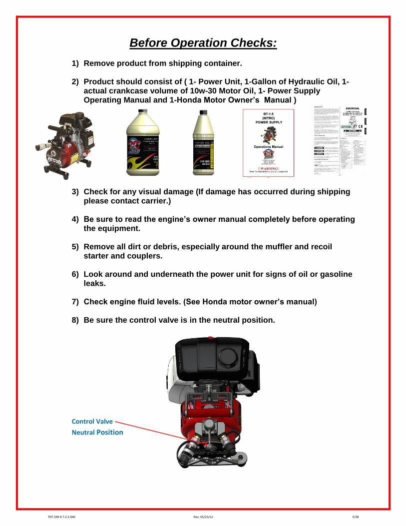
1) Remove product from shipping container.
2) Product should consist of ( 1- Power Unit, 1-Gallon of Hydraulic Oil, 1-actual crankcase volume of 10w-30 Motor Oil, 1- Power Supply Operating Manual and 1-Honda Motor Owner’s Manual )
3) Check for any visual damage (If damage has occurred during shipping please contact carrier.)
4) Be sure to read the engine’s owner manual completely before operating the equipment.
5) Remove all dirt or debris, especially around the muffler and recoil
starter and couplers.
6) Look around and underneath the power unit for signs of oil or gasoline leaks.
7) Check engine fluid levels. (See Honda motor owner’s manual)
8) Be sure the control valve is in the neutral position.
Control Valve
Neutral Position
TNT-OM # 7.2.3-040 Rev: 05/23/12 6/38
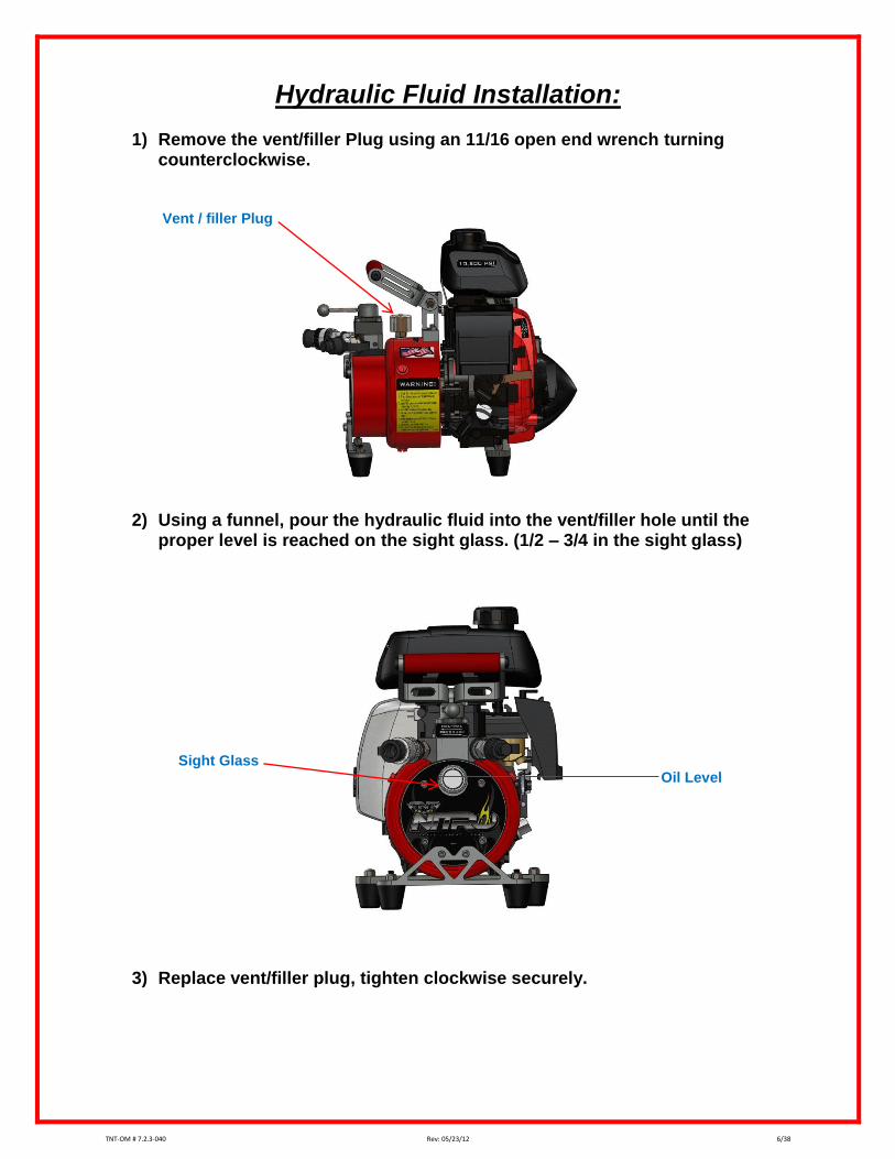
Hydraulic Fluid Installation:
1) Remove the vent/filler Plug using an 11/16 open end wrench turning counterclockwise.
Vent / filler Plug
2) Using a funnel, pour the hydraulic fluid into the vent/filler hole until the
proper level is reached on the sight glass. (1/2 – 3/4 in the sight glass) Sight Glass Oil Level
1) Rotate locking collar counter clockwise until it lines up with pin and pull back to the open position.(See Fig. 1)
2) Insert the male coupler into the female coupler and release the locking collar to the locked position. (See Fig. 2)
3) Pull on couplers to confirm a completed connection.
4) To release, rotate locking collar clockwise to line up with pin and pull back to release the male coupler.
Open Position Locked Position Insert Male Coupler
Locking Collar Pull Back Rotate Pin Female Coupler
Fig. 1 Fig. 2
TNT-OM # 7.2.3-040 Rev: 05/23/12 8/38
Flat Face 10,500 PSI Coupler Operation:
1) Insert the male coupler into the female coupler until it snaps in the locked
position.(See Fig. 1) and (Fig. 2)
2) Pull on couplers to confirm a completed connection.
3) To release, rotate locking collar clockwise until it stops and pull back to release the male coupler. (See Fig. 2)
Open Position Locked Position Insert Male Coupler Locking Collar Rotate Pull Back Female Coupler
Fig. 1 Fig. 2
TNT-OM # 7.2.3-040 Rev: 05/23/12 9/38
Standard 5,500 PSI Coupler Operation
4) Rotate locking collar counter clockwise until it lines up with ball and pull back to the open position.(See Fig. 1)
5) Insert the male coupler into the female coupler and release and rotate the locking collar clockwise to the locked position. (See Fig. 2)
6) Pull on couplers to confirm a completed connection.
7) To release, rotate locking collar counter clockwise to line up with ball and pull back to release the male coupler.
Open Position Locked Position
Male Coupler
Insert
Locking Collar
Rotate
Pull Back
Ball
Female Coupler
Fig. 1 Fig. 2
TNT-OM # 7.2.3-040 Rev: 05/23/12 10/38
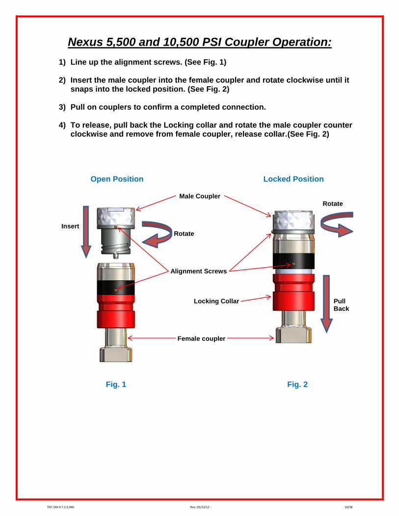
Nexus 5,500 and 10,500 PSI Coupler Operation:
1) Line up the alignment screws. (See Fig. 1)
2) Insert the male coupler into the female coupler and rotate clockwise until it snaps into the locked position. (See Fig. 2)
3) Pull on couplers to confirm a completed connection.
4) To release, pull back the Locking collar and rotate the male coupler counter
clockwise and remove from female coupler, release collar.(See Fig. 2) Open Position Locked Position Male Coupler Rotate Insert Rotate Alignment Screws Locking Collar Pull Back Female coupler
Fig. 1 Fig. 2
TNT-OM # 7.2.3-040 Rev: 05/23/12 11/38
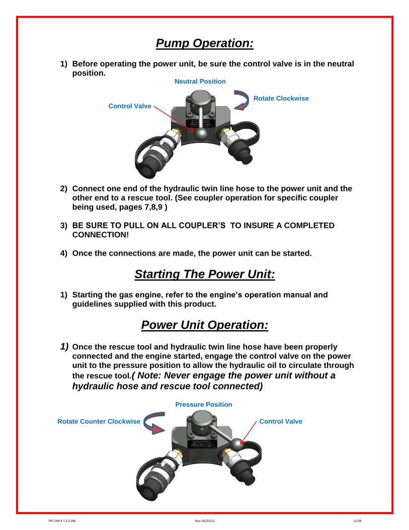
Pump Operation:
1) Before operating the power unit, be sure the control valve is in the neutral position.
Neutral Position
Rotate Clockwise Control Valve
2) Connect one end of the hydraulic twin line hose to the power unit and the other end to a rescue tool. (See coupler operation for specific coupler being used, pages 7,8,9 )
3) BE SURE TO PULL ON ALL COUPLER’S TO INSURE A COMPLETED
CONNECTION!
4) Once the connections are made, the power unit can be started.
Starting The Power Unit:
1) Starting the gas engine, refer to the engine’s operation manual and guidelines supplied with this product.
Power Unit Operation:
1) Once the rescue tool and hydraulic twin line hose have been properly connected and the engine started, engage the control valve on the power unit to the pressure position to allow the hydraulic oil to circulate through
the rescue tool.( Note: Never engage the power unit without a hydraulic hose and rescue tool connected)
Pressure Position
Rotate Counter Clockwise Control Valve
TNT-OM # 7.2.3-040 Rev: 05/23/12 12/38
Tool Operation:
1) Once the power unit, rescue tool and hydraulic twin line hose have been properly connected and the pump control valve engaged to the pressure position, the tool is ready to operate.
2) Check the operation of the rescue tool by turning the control valve on the tool to the open and closed position.(See the rescue tool operation manual) Fully open and close the rescue tool one to two times to purge any air from the system.
3) The Rescue tool is equipped with a dead man feature. When the valve is
released it will return to the neutral position and stop the operation of the rescue tool.
4) Once the use of the rescue tool is done or a tool change is needed, return the control valve on the power unit to the neutral position.(Note: TNT hydraulic hoses and rescue tools are equipped with a pressure relieving coupler, disconnecting hoses and or rescue tools with the control valve on the power unit in the pressure position will cause hydraulic fluid to be released to the environment.)
General Maintenance:
1) Disconnect hydraulic hose and rescue tool from the power unit before working on any equipment.
2) Visually inspect for loose or missing parts.
3) Check couplers for proper operation and cleanliness. Remove all dirt and debris from dust covers.
4) Check engine oil, change oil per manufacturer’s guidelines.
5) Check fuel level, fuel should be changed periodically in order to reduce the
chance of fuel problems.(See engine operation manual).
6) Check hydraulic fluid level, fill to ½ to ¾ on the sight glass.(See hydraulic fluid installation, page 6).
7) Run the power unit and operate the rescue tools, check for proper
operation of the power unit and rescue tools.
8) Clean the pump by lightly spraying with a silicone based protectant and wipe clean.
TNT-OM # 7.2.3-040 Rev: 05/23/12 13/38
Storage:
1) Never store your power unit and rescue tools under pressure.
2) Always store power unit with fuel valve off.
3) Turn the engine switch to the on position and the choke lever to the on
position to be ready for next use.
4) Store your power unit and rescue tools in a clean, dry location.
5) Be sure to store your power unit and rescue tools securely, loose tools can cause serious injury or property damage.
6) Power unit should only be stored in the upright position.
7) Do not store a hot engine in an enclosed compartment.
8) Replace dust covers on couplers.
Decontamination:
In the event your TNT rescue equipment is exposed to blood borne pathogens, chemicals, hazardous materials, etc., follow your department’s standard blood
borne/hazardous materials guidelines for equipment decontamination.
Limitations:
Your TNT rescue equipment is intended for use in automobile extrication. Due to the variety of vehicle construction styles and materials, and the inherent unpredictability of vehicle accidents, please consult your authorized TNT representative with questions regarding the limitations of these tools. The Important Safety Information (page 2) section of this manual provides basic guidelines to help ensure your safety and that of victims, bystanders, and other rescuers. TNT Rescue Systems, Inc. recommends that only trained and qualified personnel operate this equipment.
Manufacturers Data:
Your TNT rescue equipment is made in the USA. Final assembly and testing of the tool, as well as the manufacture of all major components takes place at the TNT world headquarters in Ashippun, Wisconsin. Feel free to contact TNT directly with any questions, comments, or concerns about your TNT rescue equipment.
TNT-OM # 7.2.3-040 Rev: 05/23/12 14/38
Trouble Shooting:
PROBLEM CAUSE REMEDY The couplers cannot be connected.
1) There is dirt or debris in the
coupler. 2) The system is under
pressure.
1) Remove the debris and
ensure the couplers are clean.
2) Disengage the pump.
The tool does not react when turning the valve to the open or closed position.
1) The power unit is in the
neutral position. 2) The power unit in not
running 3) The tool is not properly
connected.
4) There is an insufficient amount of hydraulic fluid in the power unit.
1) Engage the power unit.
2) Start power unit 3) Ensure that couplers are
connected.
4) Fill power unit to the proper level.
Engine will not start.
1) The switch is in the off
position.
2) The pump is engaged.
3) The oil level switch on the engine is activated.
4) The choke is in the wrong position.
5) The power unit is out of fuel.
1) Turn the switch on. 2) Return the control valve to
the neutral position. 3) Add engine oil to proper
level.
4) Adjust the choke according to the engine operation manual.
5) Check and add fuel.
Recoil will not pull.
1) The power unit is engaged.
2) The recoil case is damaged.
1) Return the control valve to
the neutral position. 2) Contact your authorized TNT
Service Representative.
*Call Your Authorized TNT Distributor For Maintenance And Annual Service Care / Preventative Maintenance.*
Daily Inspection Visually inspect all tools and components for damage, leaks and general cleanliness. Inspect couplings; insure smooth operation, clean with silicone spray if necessary. Check fluid levels in power unit:
Motor Oil
Hydraulic Oil
Fuel Operate the power unit. Run engine and power at least one tool. Allow engine to run until
normal operating temperature is reached. Add fuel if necessary.
Weekly or after use inspection Visually inspect all tools and components for damage, leaks and general cleanliness.
Additionally:
Inspect cutter blades, look for debris in yoke area
Inspect spreaders for debris in yoke area. Inspect couplings; insure smooth operation, clean with silicone spray if necessary. Check fluid levels in power unit:
Motor Oil
Hydraulic Oil
Fuel Operate the power unit. Run engine and power at least one tool. Allow engine to run until
normal operating temperature is reached. Add fuel if necessary.
Monthly Inspection Visually inspect all tools and components for damage, leaks and general cleanliness.
Additionally:
Inspect cutter blades, look for debris in yoke area
Inspect spreaders for debris in yoke area Inspect couplings; insure smooth operation, clean with silicone spray if necessary. Check fluid levels in power unit:
Motor Oil
Hydraulic Oil
Fuel Operate the power unit. Run engine and power at least one tool. Allow engine to run until
normal operating temperature is reached. Change fuel (for optimum performance never use fuel that is more than 30 days old). Clean air filter Clean spark plug, set gap (replace if necessary)- as per engine manual.
Annually Inspection Have complete system serviced by an authorized / certified technician
Note: Appropriate Personal Protective Equipment should be worn while conducting the above
maintenance. Contact an authorized TNT Service Technician if any problems are found at any time. An authorized TNT Certified Service Technician must perform annual service.