15
JUL-12-99 OS:2! F,.. :HITACHI SEIKI INt , SIC250eOOl T-i56 P.40101 Jab-345 Bt, SUPER AC SERVO SYS1'EM BL860/S)1/862 (2-axle inteqtated tYPG) Operation Manual SANYO CO., LTD. •

JUL-12-99 OS2 F HITACHI SEIKI INt SIC250eOOl T-i56 P40101 Jab-345
Bt SUPER
AC SERVO SYS1EM
BL860S)1862 (2-axle inteqtated tYPG)
Operation Manual
SANYO DE~KI CO LTD
bull
JUL-11-92 ~e23 rromHITACHI SEIKI INC 6302609081 T-m P411S5 101gt-345
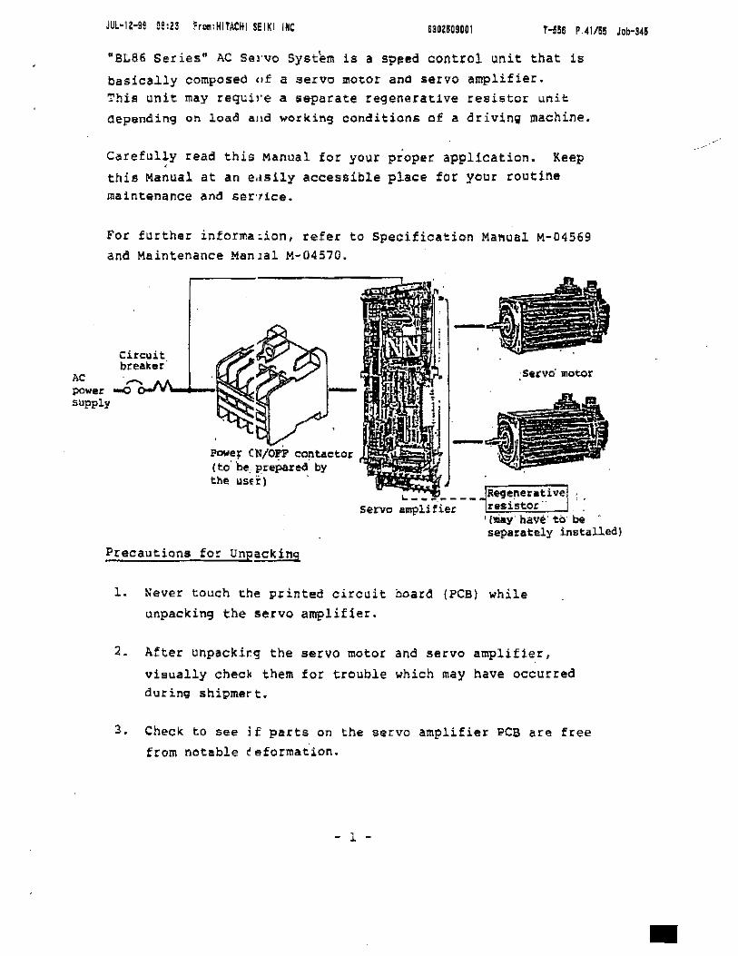
BL86 Series AC Suvo Syst~m is a sPfled control unit that is
basically composed of a servo motor and servo amplifier This unit may require a 5eparaee regenerative reehtor unit aepnding on load ai working ccnditions of a driving machine
Caref~l~y read this Manual for your proper application Keep thie Manual at an euily accessible place for your routine maintenance anti slur1ce
For further informaion refer to Specification Maual M-04569 and Maintenance Manlal M-04570
AC servo motor powusupply
OWer olon ontaetor (to be prePared by the USE 1 I
_ _ _ __ JRlgeneuUvel Servo amplifier Insisto i
(1II1i1Y have to be separately installed)
Precautions for Unpackino
1 Never touch the pinted circ~it board (PCB) while unpacking the servo amplifier
2 After unpaeklrq the servo motor and servo amplifier
visually chec~ them for trouble which may have occurred during shipmert
3 Check to see if parts on the servo amplifier PCB are free from notable ceformation
bull
- 1 shy
JUl-l-1 093 FHIT~I SEIKI INC UO509001 T-556 P4155 Job-45
4 ~ Gheck to make certain that both the servo motor and SIlrvo amplifier have type Nos spee1fe4 by you
Particular Precautitns before Use
1 Carefully protect the servo motor and servo amplifier from a shock or impILct during installation tlse partictJlllr care eo handl~ the ssrvo motor which is equipped with II
critical and fragile encoder
2 Be sure to connect the servo motor and amplifier to power supply oI 2000 230 V (10 -15) AC SD60 RZ
Othrwise serous trouble may r61sul t
3 Make Slit of tfety in operation such IUS condition of the
load before tuning power ON and OFF for maintenance and service
4 Never use theervo motor and amplifier in a place exposed to corrosive (such as acid and alkali) inflammable or explosive gas JI liquid
5 Make certain tJat the servo motor and servo amplifier are grounded in ac~ordance with electric standard Grounding Class 3 (100 11 or less)
6 ass the serVO ~otor within an ambient temperature range from Omiddot to 40 and the servo amplifier from Omiddot to 55degC Use them at a relative humidity of 90 or less
7 Protect the servo motor and servo amplifier from water cuttinq fluid and rainwater all of which would cause current leakage and a shock
8 Never carry out the withstand voltage test nor me9ser test If necessary have contact with Sanyo Denki
bull
- 2 shy
JUL-I- B924 frHITACHI $EIKI INC 6i6Z50S001 NI6 P43155 Job-345
9 Improper wirin~ could cause the servo motor and servo
amp1ifier to blealt down Strictly pound0110101 the airections given in SpecHication Manual before and during widn _
10 SL860 BLS6l 0 862 serlo motor is not an induction motor Therefore do lot try to change rotary directions of tne serlo motor by exchanging phases of the motor or input power To chaugE the otaty directiolls refer to SpQcification llanual
11 Be surt to proride the coil of the relay electromagnetic
contacto) t solmoH etc with a surge aosorber
- 3 shy
bull
JUI-12-S 0924 HITACHI SpoundIKI INC 530Z509001 T-556 P4455 JDb-45
Caution on DelivEry
Se sure to identify the servo motor and servo amplifie( by type No as shown below
Never couple the sevo amplifier with any motor having
differEnt rated pulles Be sure to collate type No of the servo amplifier witl type No of the servo motor soon atter
unpack ins
How to check type NJ
1 Type No of serVJ motor 00 aM 000 ~ 0 0 vv Q
~O~~ BL~ ~ -r- ~I ~ -r 3 Maximum continuoue torque (Te) (Note) J I I I
030 bullbullbullbull 30k9-~m 04004Abullbull 40kg-cm 06006Abullbullbull 60Kq-cm I 020 bullbullbullbull S0~9-~m 09009Abull 90kg-om 120 bullbullbullbull 120kg-cm220 bullbullbull 220kg-cm
4 Maximum revolutions lNml----------------------------~ Bbullbullbull 2000 rpm (M 1500 rpm) Rbullbullbull 2500 rpm
5 Hold brake ---------------------------------------- Xbullbullbull Not provided (standard) Bbullbull Provided
6 ~ype of detector Ebullbullbull Encoder
7 Identification of specification----------------------~
8 Order of aeign----------------------~~----------------~
Note Code Nos 04A 06A and 09A indicate Tc 40 60 and 0 kg-cm respectively but show that the resp4ct~v8 motors are designed to partic~lar
speclfications incl~ding installation size
- 4 shy
JUL-l- nS25 FrOlHITACHI SEIKI INC 8302569001 T-56 P 4555 Jalr345
2 Type No of Servo amplifier 60 BS 000 F cent M IVQ T T -r 1 T --1middotIL_====Type No of lervo motor ___-11 I IpoundHl bullbullbull SLS60
2 Symbol of 2 1 1ntllt3 bull ted type Servo lrans1stor ccllectoI clltrent ___________J
030 bullbullbull 30A (SO bullbullbull 50A 075 bullbull 75A
4 Control systEmiddotm--------------------Fbullbull 3-phase full wave system
5 Cooling fan- I Xbullbullbull Ndnel natural air circulation IIFbullbullbull Provided forced air cooling
6 Appearancestructure ________________--- I Wbullbullbull wall typElt with built- in power supply I
7 Identificati(n of pacification ___________-----Ji I S Older of C1 ign -----------------___
Accessor les of Serve Amp111ier
The servo amplifier is packed together with the following spare tor accessory) partlbull
Carefully keep sparE parts (fuses) at users responsibility
PlIrt name I Type 1 Manufacturer Cty Application
ConnaetorT llR-SOtF
liona Taushin 2 10 ci9nal oonnector Koqyo (ClUj I i
i Connector MR-20LF Honda Tsushin I 2 middot1 Encoder si9nal K09Yo oneotor (CN2j
FUIiEl DM16A (J 6A) Dilito Tampuhinki 1 Spare fus of PCl 11 IFl)
Fuse MFSlA ( II) Kowa Tanshiban 1 I Spate fuse for Seho Iprotectin9 control 1
power supply (Fl) II
- 5 shy
bull
JUl-1Z-99 0925 FrooHITACHI SEIII INC 630lt509001
Regenerative Resist(r
Th r q nerative relistor optionally available must be altlditionlllly instaled outside the servo llllPlifier for special pplication for ualllPllt the load bas great inertia the motor ill started and stopped repeatedly and frequently within II short period or the motol is appljd to a minus load For further informal1on refer to Specification Manual and drawings submi tted or approval
- 6 shy
bull
___ _________ ___ _
B~B6 Series r Combinations of Motors with Devices
Identify your servo motor and servo amplifier by type No for saoyos maintenance service 1 Standard specifjcation 1
JUL-12-~9 0926 FrosHITACHI SEI(I INC 530mSOOl T-55a P4TI$ Job-145
bull
-l SUpply510 motor ~spe1fiClition ~(l~ii tyServo amplifier ~hypeor llaquof1rO QlJ1ti COjtaetar orrYpelio 01gt1 bull fufYPe No IIV~ 6000
SOBB080FXWOOA GlJIM06DBCJEDO (5000 ) 18 46 _ __bullAAliQ ___
~__ 4 bullbull~_______ __ _---_ -- --- _shy------------~-------- 6000 GOBBOSOFXWOlA 6lBM090BDEOO ( 5000 ) 22 64
4000-------_ -_ _---- ---~--------~---- -- --~ -~- -- _- 6000
GOBBOSOFXW02A alHM060RQEClO 14 40_~ bull u _____(~gog)____ --___~__~v__________ J _---_ _---_ - ~---
6000 GOBB030FXW03A 6111M04AROEDO ( 5000 ) 14 40
__3PJlQ __ bullbull ~______-_-M--Ww- --- ~-- ---------- - ---------------~-~---~
SOBBOaOFXW70A G11IM06AMXEOO 20000 13 28 ___________w __ ______
i _______ ---- _- 1-----___ _shyM -------_ ------------shy
----_ ~ - --- - - -- ----~----_------------ --~--------------
-----_----------- --- --- _-_ -- ----_ - _----~--- -------------shy
--------------------- --------~-- --------r--------- -------t--- --- -- -- --~
---__ - - -- ___shy-------_---------- _----_-------------- -------_--shy
- 7 shy
Jut-a-ss OS26 Fr HITACKI Spoundlkl IrIC r-m P 4611 Jll-i45
2 standard specification 2
Cuneftt aci tyIhtVO mplHi~~ pl inpitt Type 110 - _tHto~ OJ
filbullbull
6000 SOBB050FXWOOA 6l3M120BOEClO (5000 ) 111 90__~_M___ ~_____________ ___ JJtQQ bull__bull _- _- _~--~------~-------- 6000 60BB060PXW01A GlJlM09ClROEOO ( 6000) 20 68 -----_ ------------ ---~--- ---------- __AOJlq -- _ _-- -
6000 ~
60BBOSOFXW1OA 62l1M080BXEClCl ( 5000) 17 49 4000----_--------- ------------------ _ - - - --_ ------ _ __
~
SOOO 60BB075FXW02A 61lM220BClEClO 150(~ggo ) 52
-------Q----------------shy6000 60l3111l75FXW03A lUI MUORQEClO 30 87(gog)- ---~-----~- -~~~--shy
6000 6pBB075FXWIOA 62EM080BXEOCl (ggU) 22 64 -- -_ - --__ _-_ _---- ---- ---q--- --~----- ---- __
--- _-_ - ---------- -- - - 1- -- __ -- --_ --- _shy
-~-----_ ------ ------------ - --- --------- --_ _ _-- _ -_ -- - --_
-- _--_ _--_ - -~--- ---- ---- -_ ---- _--_ ----- ---- --- ~
------~------~------~---- I
- S shy
bull
JUL--9 a9~r FrooHITACHI SEIKI INC 6302509001 T-15S P491i5 Job-lAS
bull
Name of Each part
~~IJ19 hole (2)lIppersid)
Chnnlictor (012)
If--+- Cttnnector (CNl)
liMe of Ilach P~rt oj servo Motoz
Mdn
4_middotunltgtI9 notch ( (2) lowei Side 1
plate ZX~Qrnal terminal
Name of Eachpart of Selvtgt AmpIifier
Adjustments
~he servo amplifier is adjusted hafora shipment $0 that a
combination of the servo amplifier with an applicable servo motor assures optimum charaoteristics Therefore never touch each
adjusting resistor unless necessary Carefully read Maintenance Manual M-04570 befera making necessary a~jusrments
Precaution -- Cheo) the adjusting resistor for position
Check to 5ee if ealth adjusting resistor points the painted llIark betor ma1ntenance or troub~e~hootins
P05it~on of painteo matk
- 9 shy
JUL-12-99 0921 FromHITACHI SIIKI INC T-55I P 50amp Job-US
axl 2 IIFr
ero aClju$tlIlInt
rR18 11 eUi 1aVR12 Gain
VlU4 Spaecl $C1
VRll Current lililit
VR20
_- - -----_
r axle 1 I
Gain VR
ZerO adjustment
CUrrent lilltHVBIl
Pl time constAnt
VR2 Speecl scale
VRI
~E2~ i
cr rn =sect CN3
j
~~ u 50112 lLl(2
w t rJrJ 8- 5
~OSW2
_______ _~w~~~____ __ ~_~___________~____________~~_ --------_ _-shy
tJ RESET
rf -- n
0 ~OSWI SN8 ~ Alarm lamp
8-1eltJl1Ient L
~I
AXle 2 alarm- ITt]1- 1- ALI( ~ Rea) WI J~e 1 alarrf IIlIP (RedlJi AX2BSN2Vtt YIn VR$ INa AXI
~ ftJ ~T
MRSTo VMOI ILOU o MOI 0150
Plo veNDI ~ El[jJ
CNI
Grollnq tetllinal
oCheek terminal)( 1 nClicaUon oJllUIpper pin lamp(ul)l
(Geen)Layout of PCB PI
- 10 shy
bull
JUL-IN9 0121 FromHtTACIII SEIKI IMe BSm09001 T-m P5UU Job-145
2 To Check the m01or for revolutions and current (torques) obllllrve the wav~lform with the speed monitor and cur rent
monitor of the connector CN~ ubullbull iii measuring device with input impedance of 1 Mn or mOre
to observe the weform
( Speed monito (VMOil bullbullbullbullbull ilV iSi1000rpm rgtI nCmiddot)n t ae t or CNl Van l)I3 plns
pin 0 is a OO1ll1llon pin)
Current rnoni~or (IMO~) bullbull TlOV +20Maximum continuous armature current
Clntactor CNi pins ~ and 9 ( in 0 is a cOMon pin)
When VMO voltae and 1)010 voltage are measuted revolutions (N) and a load torque tTL) may be found in the followingequations
lKO voltageRevolutions (N) N =1000 xr 3(rpm)
IMO volta5lei Load torque tTL) Tr lPS X 10 ( kg-clII)
(whete TpS =maximum continuous torque)
bull
- 12 shy
JUl-12-Sa nezs FHITACHI SElkl IftC 6302109001
Servo Error
1 Trouble indicatir lamp
when the trouble inoicAting lAmp (B-sement LED rea) turna
ON identify the indicated trouble by the lighting segment according to the following table Pres the RESET (iWl) push-button I or lurn power lIupply OFF
2 Type anll abbreviation of alarm
Refer to Maintenlnce Manual for trOUbleshooting in detail
Abbre- Sl1iment Action withContent of alarmviation j indioation $UVO AmplifierI
oc lOver cunent in the motOr and V bllS I I
i I01 ]] Moto~ is overloaded
I Oli [jJ Heat sink is I1 I overheateo I
CB i [) MCB (circuit pro- Servo amplifier has tector) is opened power Circuit opened
at the base I I
OV I rn Regenerative resistor is in trouble I
I (voltage time)
OS 1 ~ OlTerpeed bull Servo amplifier iii self-maintaininguntil being reset
Pl [1J Power supply trouble (15V)1
DE rnJ tensor trouble I Tha serlTo alarm is OUtPllt
lIPI [iJ iMain circuit (DC)1IT01tage drops I
bull
- 13 shy
JUl-12-ii 0929 FrHITACHI SEIKI IHe samOiOOl T-Ie Pmiddot45 Joo-I45
Abbre- Segment Action with IContent of ~larmriation indication IelVO amplifier
FP [ID Main power supply middot The alalm is turned lacks ill phaI into II code signal
output to theI i interface I
I SE j lo1terrlln
~ [] Turneacpu trQuble bull Servo ~mplifier has OFF power circuit
opened at the base middot Servo amplifier is
self-maintaining until being ~e5et
middot The signal Servo Alarm is outputI i
A dot keeps lighting IGl during normal operation i
Note Classifica~ion between axle 1 and axle 2 is performedby the inaicator (LED RED)
bull
- 14 shy
JUl-ll- 09ID Fr HITACHI SEIKI INC
Maintenance
Neither the servo mtor ncr servo amplifier requires special maintenance Perfom the Simplest maintenance shown below for
j
I
1
I
longer service life of the sr~o motor
Check procedure
Check cond ltionl I Object Check
Servo motor
Inter- OUt i9 During item val ioper- ill stop
tion
Routine 0
Routine 0
1 i
I 1
A j re-I qui
i One year
5000 houri2
i servo As ampli~ reshyfier quired
One I year I I
I
Vibratlon
I i Sound
0 Cleaning
0 Measure insulation
Check methoO
ICheck whether vibration is larger than iusual
Check whether unusual sound oocurs
Chack iappearance ior $011 anCi ldirt
I
Countershymeasures
Eave contact with Sanyo Danki
Clean with rags or oompd air bullbull 1
I resistance Have contact with I sanyo Oellk i
) I Replace oil ~ seal ~
0 ICleaning
0 Loosen a screws
i
I
and servo amplifir
I Check whether Clean with
dirt deposits compressed Ion mounted parts
Check the e~ternal ter-Iminal and connectors
leNl and CN2Ifor screws
ir1
IHe-tightenloosened screws
1 Checllt to tlH1Ke certain that COllll ltl ai is free from oil mist moisture and other foreign matter before cleaning
2 Indicates that the servo motor is intended for II waterproof or oil-proof application and should therefore be checked or replaced at thiS interval
- 15 shy
bull
JUL-11-92 ~e23 rromHITACHI SEIKI INC 6302609081 T-m P411S5 101gt-345
BL86 Series AC Suvo Syst~m is a sPfled control unit that is
basically composed of a servo motor and servo amplifier This unit may require a 5eparaee regenerative reehtor unit aepnding on load ai working ccnditions of a driving machine
Caref~l~y read this Manual for your proper application Keep thie Manual at an euily accessible place for your routine maintenance anti slur1ce
For further informaion refer to Specification Maual M-04569 and Maintenance Manlal M-04570
AC servo motor powusupply
OWer olon ontaetor (to be prePared by the USE 1 I
_ _ _ __ JRlgeneuUvel Servo amplifier Insisto i
(1II1i1Y have to be separately installed)
Precautions for Unpackino
1 Never touch the pinted circ~it board (PCB) while unpacking the servo amplifier
2 After unpaeklrq the servo motor and servo amplifier
visually chec~ them for trouble which may have occurred during shipmert
3 Check to see if parts on the servo amplifier PCB are free from notable ceformation
bull
- 1 shy
JUl-l-1 093 FHIT~I SEIKI INC UO509001 T-556 P4155 Job-45
4 ~ Gheck to make certain that both the servo motor and SIlrvo amplifier have type Nos spee1fe4 by you
Particular Precautitns before Use
1 Carefully protect the servo motor and servo amplifier from a shock or impILct during installation tlse partictJlllr care eo handl~ the ssrvo motor which is equipped with II
critical and fragile encoder
2 Be sure to connect the servo motor and amplifier to power supply oI 2000 230 V (10 -15) AC SD60 RZ
Othrwise serous trouble may r61sul t
3 Make Slit of tfety in operation such IUS condition of the
load before tuning power ON and OFF for maintenance and service
4 Never use theervo motor and amplifier in a place exposed to corrosive (such as acid and alkali) inflammable or explosive gas JI liquid
5 Make certain tJat the servo motor and servo amplifier are grounded in ac~ordance with electric standard Grounding Class 3 (100 11 or less)
6 ass the serVO ~otor within an ambient temperature range from Omiddot to 40 and the servo amplifier from Omiddot to 55degC Use them at a relative humidity of 90 or less
7 Protect the servo motor and servo amplifier from water cuttinq fluid and rainwater all of which would cause current leakage and a shock
8 Never carry out the withstand voltage test nor me9ser test If necessary have contact with Sanyo Denki
bull
- 2 shy
JUL-I- B924 frHITACHI $EIKI INC 6i6Z50S001 NI6 P43155 Job-345
9 Improper wirin~ could cause the servo motor and servo
amp1ifier to blealt down Strictly pound0110101 the airections given in SpecHication Manual before and during widn _
10 SL860 BLS6l 0 862 serlo motor is not an induction motor Therefore do lot try to change rotary directions of tne serlo motor by exchanging phases of the motor or input power To chaugE the otaty directiolls refer to SpQcification llanual
11 Be surt to proride the coil of the relay electromagnetic
contacto) t solmoH etc with a surge aosorber
- 3 shy
bull
JUI-12-S 0924 HITACHI SpoundIKI INC 530Z509001 T-556 P4455 JDb-45
Caution on DelivEry
Se sure to identify the servo motor and servo amplifie( by type No as shown below
Never couple the sevo amplifier with any motor having
differEnt rated pulles Be sure to collate type No of the servo amplifier witl type No of the servo motor soon atter
unpack ins
How to check type NJ
1 Type No of serVJ motor 00 aM 000 ~ 0 0 vv Q
~O~~ BL~ ~ -r- ~I ~ -r 3 Maximum continuoue torque (Te) (Note) J I I I
030 bullbullbullbull 30k9-~m 04004Abullbull 40kg-cm 06006Abullbullbull 60Kq-cm I 020 bullbullbullbull S0~9-~m 09009Abull 90kg-om 120 bullbullbullbull 120kg-cm220 bullbullbull 220kg-cm
4 Maximum revolutions lNml----------------------------~ Bbullbullbull 2000 rpm (M 1500 rpm) Rbullbullbull 2500 rpm
5 Hold brake ---------------------------------------- Xbullbullbull Not provided (standard) Bbullbull Provided
6 ~ype of detector Ebullbullbull Encoder
7 Identification of specification----------------------~
8 Order of aeign----------------------~~----------------~
Note Code Nos 04A 06A and 09A indicate Tc 40 60 and 0 kg-cm respectively but show that the resp4ct~v8 motors are designed to partic~lar
speclfications incl~ding installation size
- 4 shy
JUL-l- nS25 FrOlHITACHI SEIKI INC 8302569001 T-56 P 4555 Jalr345
2 Type No of Servo amplifier 60 BS 000 F cent M IVQ T T -r 1 T --1middotIL_====Type No of lervo motor ___-11 I IpoundHl bullbullbull SLS60
2 Symbol of 2 1 1ntllt3 bull ted type Servo lrans1stor ccllectoI clltrent ___________J
030 bullbullbull 30A (SO bullbullbull 50A 075 bullbull 75A
4 Control systEmiddotm--------------------Fbullbull 3-phase full wave system
5 Cooling fan- I Xbullbullbull Ndnel natural air circulation IIFbullbullbull Provided forced air cooling
6 Appearancestructure ________________--- I Wbullbullbull wall typElt with built- in power supply I
7 Identificati(n of pacification ___________-----Ji I S Older of C1 ign -----------------___
Accessor les of Serve Amp111ier
The servo amplifier is packed together with the following spare tor accessory) partlbull
Carefully keep sparE parts (fuses) at users responsibility
PlIrt name I Type 1 Manufacturer Cty Application
ConnaetorT llR-SOtF
liona Taushin 2 10 ci9nal oonnector Koqyo (ClUj I i
i Connector MR-20LF Honda Tsushin I 2 middot1 Encoder si9nal K09Yo oneotor (CN2j
FUIiEl DM16A (J 6A) Dilito Tampuhinki 1 Spare fus of PCl 11 IFl)
Fuse MFSlA ( II) Kowa Tanshiban 1 I Spate fuse for Seho Iprotectin9 control 1
power supply (Fl) II
- 5 shy
bull
JUl-1Z-99 0925 FrooHITACHI SEIII INC 630lt509001
Regenerative Resist(r
Th r q nerative relistor optionally available must be altlditionlllly instaled outside the servo llllPlifier for special pplication for ualllPllt the load bas great inertia the motor ill started and stopped repeatedly and frequently within II short period or the motol is appljd to a minus load For further informal1on refer to Specification Manual and drawings submi tted or approval
- 6 shy
bull
___ _________ ___ _
B~B6 Series r Combinations of Motors with Devices
Identify your servo motor and servo amplifier by type No for saoyos maintenance service 1 Standard specifjcation 1
JUL-12-~9 0926 FrosHITACHI SEI(I INC 530mSOOl T-55a P4TI$ Job-145
bull
-l SUpply510 motor ~spe1fiClition ~(l~ii tyServo amplifier ~hypeor llaquof1rO QlJ1ti COjtaetar orrYpelio 01gt1 bull fufYPe No IIV~ 6000
SOBB080FXWOOA GlJIM06DBCJEDO (5000 ) 18 46 _ __bullAAliQ ___
~__ 4 bullbull~_______ __ _---_ -- --- _shy------------~-------- 6000 GOBBOSOFXWOlA 6lBM090BDEOO ( 5000 ) 22 64
4000-------_ -_ _---- ---~--------~---- -- --~ -~- -- _- 6000
GOBBOSOFXW02A alHM060RQEClO 14 40_~ bull u _____(~gog)____ --___~__~v__________ J _---_ _---_ - ~---
6000 GOBB030FXW03A 6111M04AROEDO ( 5000 ) 14 40
__3PJlQ __ bullbull ~______-_-M--Ww- --- ~-- ---------- - ---------------~-~---~
SOBBOaOFXW70A G11IM06AMXEOO 20000 13 28 ___________w __ ______
i _______ ---- _- 1-----___ _shyM -------_ ------------shy
----_ ~ - --- - - -- ----~----_------------ --~--------------
-----_----------- --- --- _-_ -- ----_ - _----~--- -------------shy
--------------------- --------~-- --------r--------- -------t--- --- -- -- --~
---__ - - -- ___shy-------_---------- _----_-------------- -------_--shy
- 7 shy
Jut-a-ss OS26 Fr HITACKI Spoundlkl IrIC r-m P 4611 Jll-i45
2 standard specification 2
Cuneftt aci tyIhtVO mplHi~~ pl inpitt Type 110 - _tHto~ OJ
filbullbull
6000 SOBB050FXWOOA 6l3M120BOEClO (5000 ) 111 90__~_M___ ~_____________ ___ JJtQQ bull__bull _- _- _~--~------~-------- 6000 60BB060PXW01A GlJlM09ClROEOO ( 6000) 20 68 -----_ ------------ ---~--- ---------- __AOJlq -- _ _-- -
6000 ~
60BBOSOFXW1OA 62l1M080BXEClCl ( 5000) 17 49 4000----_--------- ------------------ _ - - - --_ ------ _ __
~
SOOO 60BB075FXW02A 61lM220BClEClO 150(~ggo ) 52
-------Q----------------shy6000 60l3111l75FXW03A lUI MUORQEClO 30 87(gog)- ---~-----~- -~~~--shy
6000 6pBB075FXWIOA 62EM080BXEOCl (ggU) 22 64 -- -_ - --__ _-_ _---- ---- ---q--- --~----- ---- __
--- _-_ - ---------- -- - - 1- -- __ -- --_ --- _shy
-~-----_ ------ ------------ - --- --------- --_ _ _-- _ -_ -- - --_
-- _--_ _--_ - -~--- ---- ---- -_ ---- _--_ ----- ---- --- ~
------~------~------~---- I
- S shy
bull
JUL--9 a9~r FrooHITACHI SEIKI INC 6302509001 T-15S P491i5 Job-lAS
bull
Name of Each part
~~IJ19 hole (2)lIppersid)
Chnnlictor (012)
If--+- Cttnnector (CNl)
liMe of Ilach P~rt oj servo Motoz
Mdn
4_middotunltgtI9 notch ( (2) lowei Side 1
plate ZX~Qrnal terminal
Name of Eachpart of Selvtgt AmpIifier
Adjustments
~he servo amplifier is adjusted hafora shipment $0 that a
combination of the servo amplifier with an applicable servo motor assures optimum charaoteristics Therefore never touch each
adjusting resistor unless necessary Carefully read Maintenance Manual M-04570 befera making necessary a~jusrments
Precaution -- Cheo) the adjusting resistor for position
Check to 5ee if ealth adjusting resistor points the painted llIark betor ma1ntenance or troub~e~hootins
P05it~on of painteo matk
- 9 shy
JUL-12-99 0921 FromHITACHI SIIKI INC T-55I P 50amp Job-US
axl 2 IIFr
ero aClju$tlIlInt
rR18 11 eUi 1aVR12 Gain
VlU4 Spaecl $C1
VRll Current lililit
VR20
_- - -----_
r axle 1 I
Gain VR
ZerO adjustment
CUrrent lilltHVBIl
Pl time constAnt
VR2 Speecl scale
VRI
~E2~ i
cr rn =sect CN3
j
~~ u 50112 lLl(2
w t rJrJ 8- 5
~OSW2
_______ _~w~~~____ __ ~_~___________~____________~~_ --------_ _-shy
tJ RESET
rf -- n
0 ~OSWI SN8 ~ Alarm lamp
8-1eltJl1Ient L
~I
AXle 2 alarm- ITt]1- 1- ALI( ~ Rea) WI J~e 1 alarrf IIlIP (RedlJi AX2BSN2Vtt YIn VR$ INa AXI
~ ftJ ~T
MRSTo VMOI ILOU o MOI 0150
Plo veNDI ~ El[jJ
CNI
Grollnq tetllinal
oCheek terminal)( 1 nClicaUon oJllUIpper pin lamp(ul)l
(Geen)Layout of PCB PI
- 10 shy
bull
JUL-IN9 0121 FromHtTACIII SEIKI IMe BSm09001 T-m P5UU Job-145
2 To Check the m01or for revolutions and current (torques) obllllrve the wav~lform with the speed monitor and cur rent
monitor of the connector CN~ ubullbull iii measuring device with input impedance of 1 Mn or mOre
to observe the weform
( Speed monito (VMOil bullbullbullbullbull ilV iSi1000rpm rgtI nCmiddot)n t ae t or CNl Van l)I3 plns
pin 0 is a OO1ll1llon pin)
Current rnoni~or (IMO~) bullbull TlOV +20Maximum continuous armature current
Clntactor CNi pins ~ and 9 ( in 0 is a cOMon pin)
When VMO voltae and 1)010 voltage are measuted revolutions (N) and a load torque tTL) may be found in the followingequations
lKO voltageRevolutions (N) N =1000 xr 3(rpm)
IMO volta5lei Load torque tTL) Tr lPS X 10 ( kg-clII)
(whete TpS =maximum continuous torque)
bull
- 12 shy
JUl-12-Sa nezs FHITACHI SElkl IftC 6302109001
Servo Error
1 Trouble indicatir lamp
when the trouble inoicAting lAmp (B-sement LED rea) turna
ON identify the indicated trouble by the lighting segment according to the following table Pres the RESET (iWl) push-button I or lurn power lIupply OFF
2 Type anll abbreviation of alarm
Refer to Maintenlnce Manual for trOUbleshooting in detail
Abbre- Sl1iment Action withContent of alarmviation j indioation $UVO AmplifierI
oc lOver cunent in the motOr and V bllS I I
i I01 ]] Moto~ is overloaded
I Oli [jJ Heat sink is I1 I overheateo I
CB i [) MCB (circuit pro- Servo amplifier has tector) is opened power Circuit opened
at the base I I
OV I rn Regenerative resistor is in trouble I
I (voltage time)
OS 1 ~ OlTerpeed bull Servo amplifier iii self-maintaininguntil being reset
Pl [1J Power supply trouble (15V)1
DE rnJ tensor trouble I Tha serlTo alarm is OUtPllt
lIPI [iJ iMain circuit (DC)1IT01tage drops I
bull
- 13 shy
JUl-12-ii 0929 FrHITACHI SEIKI IHe samOiOOl T-Ie Pmiddot45 Joo-I45
Abbre- Segment Action with IContent of ~larmriation indication IelVO amplifier
FP [ID Main power supply middot The alalm is turned lacks ill phaI into II code signal
output to theI i interface I
I SE j lo1terrlln
~ [] Turneacpu trQuble bull Servo ~mplifier has OFF power circuit
opened at the base middot Servo amplifier is
self-maintaining until being ~e5et
middot The signal Servo Alarm is outputI i
A dot keeps lighting IGl during normal operation i
Note Classifica~ion between axle 1 and axle 2 is performedby the inaicator (LED RED)
bull
- 14 shy
JUl-ll- 09ID Fr HITACHI SEIKI INC
Maintenance
Neither the servo mtor ncr servo amplifier requires special maintenance Perfom the Simplest maintenance shown below for
j
I
1
I
longer service life of the sr~o motor
Check procedure
Check cond ltionl I Object Check
Servo motor
Inter- OUt i9 During item val ioper- ill stop
tion
Routine 0
Routine 0
1 i
I 1
A j re-I qui
i One year
5000 houri2
i servo As ampli~ reshyfier quired
One I year I I
I
Vibratlon
I i Sound
0 Cleaning
0 Measure insulation
Check methoO
ICheck whether vibration is larger than iusual
Check whether unusual sound oocurs
Chack iappearance ior $011 anCi ldirt
I
Countershymeasures
Eave contact with Sanyo Danki
Clean with rags or oompd air bullbull 1
I resistance Have contact with I sanyo Oellk i
) I Replace oil ~ seal ~
0 ICleaning
0 Loosen a screws
i
I
and servo amplifir
I Check whether Clean with
dirt deposits compressed Ion mounted parts
Check the e~ternal ter-Iminal and connectors
leNl and CN2Ifor screws
ir1
IHe-tightenloosened screws
1 Checllt to tlH1Ke certain that COllll ltl ai is free from oil mist moisture and other foreign matter before cleaning
2 Indicates that the servo motor is intended for II waterproof or oil-proof application and should therefore be checked or replaced at thiS interval
- 15 shy
bull
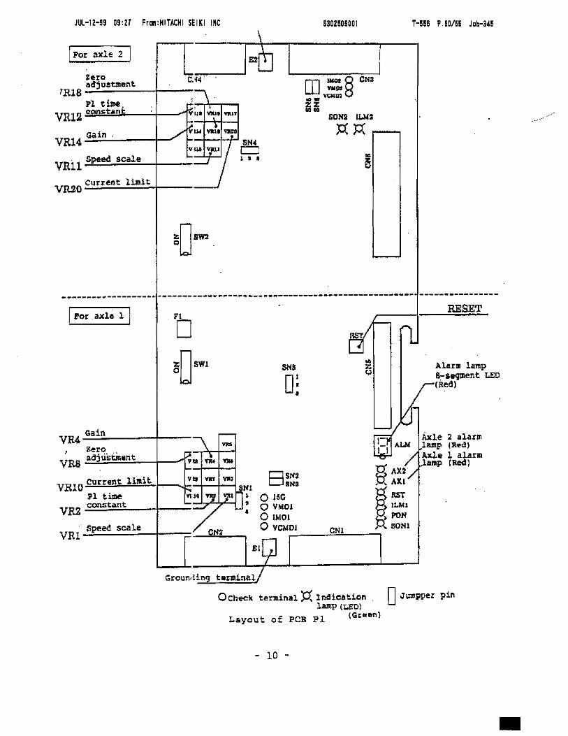
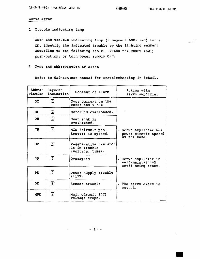
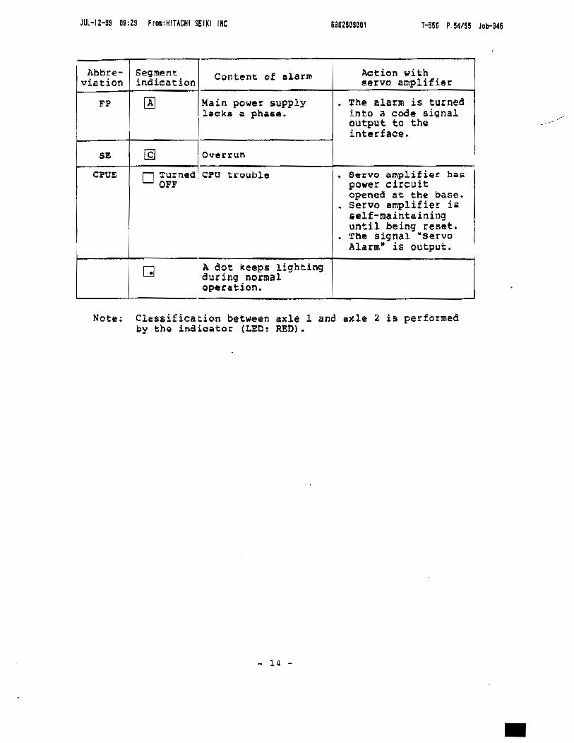


![Untitled-1 [starhealth.in] Untitled-1 Author: sys1 Created Date: 6/13/2015 10:28:39 AM](https://static.documents.pub/doc/80x56/5abc214e7f8b9a24028d7292/untitled-1-untitled-1-author-sys1-created-date-6132015-102839-am.jpg)


