SCREWLine³ Nominal cooling capacity from 550 kW to 1427 kW ▶ Single refrigeration circuit with twin screw compressor R-134a ▶ Modulating capacity control (stepless) down to 12.5% of the load ▶ Leaving temperature down to -12°C Technical Bulletin Condenserless liquid chiller MDE-SL3 220.2 - 580.2 RANGE EXCELLENCE version BT14G017GB-01
Transcript
SCREWLine³
Nominal cooling capacity from 550 kW to 1427 kW
▶ Single refrigeration circuit with twin screw compressor R-134a
▶ Modulating capacity control (stepless) down to 12.5% of the load
▶ Leaving temperature down to -12°C
Technical Bulletin
Condenserless liquid chiller
MDE-SL3 220.2 - 580.2 RANGE
EXCELLENCE version
BT14G017GB-01
2 SCREWLine³ BT14G017GB-01
Features and Benefits
Excellent operating economy
Cutting-edge energy efficiency in its category ▶ Eurovent Class A energy efficiency ▶ EER up to 4.4 at full load operation ▶ High efficiency at part loads with continuous capacity partialization
Perfect matching of the supplied capacity to the load ▶ Modulating capacity control (stepless) down to 12.5% of the load ▶ Electronic expansion valve: it quickly adapts to the actual load, controls in a more precise and firmer way than mechanical
thermostatic valves, controls the superheating and increases the efficiency and compressor lifetime
Superior heat exchange efficiency ▶ Dry expansion shell and tube evaporator at single pass in perfect counterflow: higher exchange efficiency ▶ Single evaporator for both circuits: it maximizes the efficiency with one compressor in operation
DST Control (Dynamic Supply Temperature) available for additional energy saving
Great application versatility
Chilled water down to –8°C (Brine configuration). On request: chilled water down to –12°C
Environmental care
Ecological refrigerant R-134a ▶ It does not contain chlorine: ODP (Ozone Depletion Potential) equal to 0 Reduced quantity: it contributes to LEED credits for
Green Buildings ▶ Reduced quantity: it contributes to LEED credits for Green Buildings
Safety against refrigerant leaks ▶ All pressure gauges and equipment are already on board ▶ PED Certification (Pressure Equipment Directive)
Easy and fast installation and start-up
Compact design: the reduced width permits an easy access to plant rooms
Quick installation
▶ Easily accessible lifting points ▶ Simplified hydronic connections, Victaulic type ▶ Practical reference marks for entering and leaving water connections
Easy electrical connection
▶ Just one power supply point for the unit ▶ Power supply to low voltage control devices integrated into the unit ▶ Multifunction phase monitor supplied as standard: it controls the presence and the correct
phase sequences, verifies possible voltage anomalies (-10%), it automatically resets the unit operation, when the correct power supply is re-established
▶ User contacts are easily accessible and with connection details available on the Installation, Use and Maintenance Manual.
BT14G017GB-01 SCREWLine³ 3
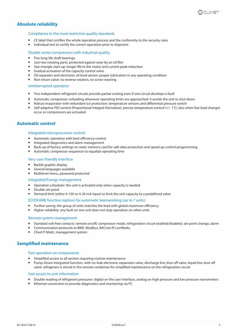
Absolute reliability
Compliance to the most restrictive quality standards
▶ CE label that certifies the whole operation process and the conformity to the security rules ▶ Individual test to certify the correct operation prior to shipment
Double screw compressors with industrial quality ▶ Five long-life shaft bearings ▶ Just two rotating parts, protected against wear by an oil film ▶ Star-triangle start-up: longer life to the motor and current peak reduction ▶ Gradual activation of the capacity control valve ▶ Oil separator and electronic oil level sensor: proper lubrication in any operating condition ▶ Non return valve: no reverse rotation, no screw wearing
Uninterrupted operation
▶ Two independent refrigerant circuits provide partial cooling even if one circuit develops a fault
▶ Automatic compressor unloading whenever operating limits are approached: it avoids the unit to shut down ▶ Robust evaporator with redundant ice protection: temperature sensors and differential pressure switch ▶ Self-adaptive PID control (Proportional-Integral-Derivative): precise temperature control (+/- 1°C) also when fast load changes
occur or compressors are activated
Automatic control
Integrated microprocessor control: ▶ Automatic operation with best efficiency control ▶ Integrated diagnostics and alarm management ▶ Back-up of factory settings on static memory card for safe data protection and speed up control programming ▶ Automatic compressor sequencer to equalize operating time
Very user-friendly interface ▶ Backlit graphic display ▶ Several languages available ▶ Multilevel menu, password protected
Integrated Energy management ▶ Operation scheduler: the unit is activated only when capacity is needed ▶ Double set-point ▶ Demand limit (either 0-10V or 4-20 mA input) to limit the unit capacity to a predefined value
ECOSHARE function (option) for automatic teamworking (up to 7 units) ▶ Further saving: the group of units matches the load with global maximum efficiency ▶ Higher reliability: any fault on one unit does not stop operation on other units
Remote system management ▶ Standard volt-free contacts: remote on/off, compressor mode, refrigeration circuit enabled/disabled, set-point change, alarm ▶ Communication protocols to BMS: Modbus, BACnet-IP, LonWorks ▶ Clivet P-Matic, management system
Semplified maintenance
Fast operation on components ▶ Simplified access to all section requiring routine maintenance ▶ Pump-Down integrated function, with no-leak electronic expansion valve, discharge line shut-off valve, liquid line shut-off
valve: refrigerant is stored in the remote condenser for simplified maintenance on the refrigeration circuit
Fast access to unit information ▶ Double reading of refrigerant pressures: digital on the user interface, analog on high pressure and low pressure manometers ▶ Ethernet connection to provide diagnostics and monitoring via PC
4 SCREWLine³ BT14G017GB-01
Unit configurability
(1) RangeMDE = Liquid chiller, water cooled, with screw compressorsSL3 = SCREWLine3 range
(2) Size580 = Nominal compressor capacity (HP)
(3) Compressors2 = Compressor quantity
(4) Energy efficiencyEXC = EXCELLENCE version: high energy efficiency
(6) Low evaporator water temperature- = Low water temperature: not required (standard)B = Low water temperature, down to –8°C (Brine)‘Very low water temperature’, down to –12°C, is available on request
ConfigurationsEN - Super-silenced configurationConfiguration used to increase the unit’s silent operation by acting on the source of the noise. It consists of suitable steel casings lined with high-density material designed to provide sound insulation. The casings are secured to an aluminium frame and painted on the outside with polyester powder (RAL 9001).
To assess the quality of the soundproofing benefit, refer to the ‘Sound levels’ tables.
B - Water low temperature (Brine)Configuration also known as “Brine”. Enables an “unfreezable” solution to be cooled (for example, water and ethylene glycol in suitable quantities) up to a temperature of between +4°C and –8°C. It includes:
• suitable exchangers with extra-thick closed-cell insulation
• electronic expansion valve, functional calibration and safety devices suitable for particular uses.
During the selection phase it is necessary to indicate the required operating type, the unit will be optimised on the basis of this: - Unit with single operating set-point (only at low temperature) - Unit with double operating set-point
The unit in this configuration has a different operating field, which was reported in the previous pages.
In low temperature operation, some staging steps could not be available.
The glycol concentration must be chosen based on the minimum temperature the water can reach. The presence of glycol influences pressure drops on the water side and the unit’s output as indicated in the table reporting the ”correction factors for use with glycol”.
“The “Extremely low water temperature” option for the chilled water production down to -12°C is available on request.
Correction factor for water low temperatureEvaporator outlet water temperature factor 2 0 -2 -4
Cooling capacity factor 0.860 0.803 0.749 0.691
Compressor power input factor 0.896 0.878 0.859 0.840
The correction coefficients must be applied to condition: internal exchanger water (evaporator) = 12 / 7 °C
Example: Determine the performance with leaving water temperature –4°C for MDE-SL3 320.2 EXC ST B unit (‘Excellence’ version, ‘Water low temperature (Brine)’ acoustic configuration) with condenser temperature 45 °C, 30% glycolFrom the performance table referred to condenser temperature 45°C and the internal exchanger leaving water temperature (evaporator) 7°C) Cooling capacity = 794 kW, Compressor power input = 181 kW From the correction factor table for water low temperature: 0.692 for the cooling capacity and 0.879 for the compressor power input (leaving water temperature –4°C).From the glycol correction factor : 0.964 for the cooling capacity , 1.007 for the compressor power input , 1.072 for the glycol solution flow, 1.3 for the evaporator pressure drop (glycol 30%).Calculation MDE-SL3 320.2 EXC ST B: Cooling capacity = 794 x 0.692 x 0.964 = 529.7 kW, Compressor power input = 181 x 0.879 x 1.007 = 160.2 kW, Water flow rate = 25.3 (calcolata su 529.7 kW) x 1.072 = 27.1 l/s, Evaporator pressure drop = 26 (calcolata su 25.3 l/s) x 1.3 = 33.8 kPa
BT14G017GB-01 SCREWLine³ 5
Standard unit technical specificationsCompressorCompact semi hermetic helicoidal twin screw compressors: the main screw (male, with five lobes) is driven directly by the electric motor, while the secondary screw (female with six vanes) is driven by the primary one. Continuous modulation of the cooling capacity supplied with no-load start-up. The tightness is guaranteed by the extremely accurate tolerances in processing all the moving parts and specific oil circulation between the screws. The free flow lubrication system resulting from pressure differences, is equipped with a highly efficient separator, level indicator and oil filter (replaceable). An oil heater prevents excessive dilution of the oil by the refrigerant, and is automatically activated at all stages where the compressor is switched off. Electronic control of the oil level shown on a graphical display. The asynchronous three-phase two-pole motor is suction gas cooled, reduced load start of star delta type. Fully protected electronic module, with safety sensor for monitoring discharge temperature, sensors for monitoring maximum temperature of the windings, device to monitor the motor rotation direction and device to monitor absence of phase. Cut-off valve on the discharge line of the refrigerant. Filter on the supply line, at the compressor inlet. Built-in attenuator and non return valve on the compressor’s drain. Automatic safety valve inside the compressor between the high pressure (HP) and low pressure (LP) areas.
EvaporatorDirect expansion exchanger with refrigerant side independent circuit for each compressor. The exchanger is composed of a cover made of carbon steel. The tubes, anchored to the tube plate by mechanical expansion, are made of copper, high efficiency, internally rifled to improve thermal exchange and specially designed for use with modern ecological refrigerants. This is a single-step exchanger with perfect counter-current between the water and the refrigerant. Moreover, it comes with a protection differential pressure switch on the water side and a coating made with closed-cell thermal-insulating material to prevent condensation and heat transfer towards the outside environment. The exchanger water connections are quick type with splined joint.
Refrigeration circuitThe units are made with two independent refrigeration circuits, each with:
• electronic expansion valve
• high pressure safety pressure switch
• low pressure safety valve (safety valve with shut-off valve sealed with lead, open for possible inspection)
• high pressure safety valve (safety valve with shut-off valve sealed with lead, open for possible inspection)
• high and low pressure gauges
• replaceable anti-acid solid cartridge dehydrator filter with connection for refrigerant quick charge
• sight glass with moisture and liquid indicator
• cutoff valve on compressor supply
• cutoff valve on liquid line
Electrical panelThe capacity section includes:
• main door lock isolator switch (compulsory to have certification CE)
• isolating transformer for auxiliary circuit power supply
• compressor fuses and thermal overload relay
• compressor control contactor
The control section includes:
• derivative-integral-proportional control of the water temperature
• antifreeze protection
• unit switching on management by local or remote (serial)
• compressor overload protection and timer
• potential-free contacts for compressor status and enabling
• self-diagnosis system with immediate display of the error code
• prealarm function for high refrigerant gas pressurethat avoids in many cases the unit block
• compressor operating hour display
• multifunction phase monitor
• remote ON/OFF control
• remote COOL control
• second set-point enabling by potential-free contact
• automatic compressor start rotation control
• relay for remote cumulative fault signal
• display of the set values, the error codes and the parameter index
• high refrigerant gas pressure pre-alarm function that in many cases prevents the unit from being shut-down
• inlet for demand limit (power input limitation according to a 0÷10V or 4-20 mA external signal)
• Power factor correction capacitors (cosfi > 0.9)
• Energy meter
• Set-point compensation with outdoor air temperature probe
• Set-point compensation with signal 0-10 V
• Set-point compensation with signal 4-20 mA
• BACnet-IP serial communication module
• LonWorks serial communication module
• Modbus serial communication module
• Remote microprocessor control unit (separately supplied accessories)
• Mains power supply unit (accessory separately supplied)
• ECOSHARE function
TestAll the units are factory-tested in specific steps, before shipping them. After the approval, the moisture contents present in all circuits are analyzed, in order to ensure the respect of the limits set by the manufacturers of the different components.
6 SCREWLine³ BT14G017GB-01
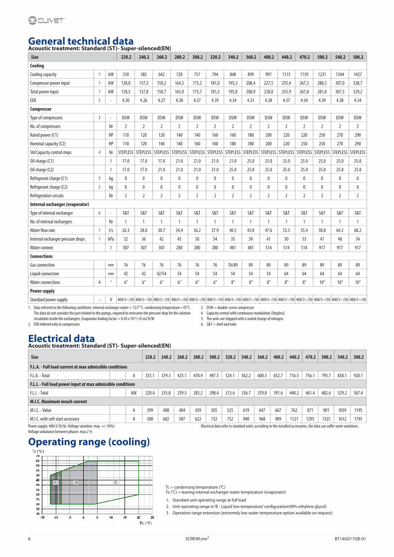
General technical dataAcoustic treatment: Standard (ST)- Super-silenced(EN)
M.I.C. - Value A 399 408 404 439 505 525 619 647 667 762 871 901 1039 1195
M.I.C. with soft start accessory A 588 602 587 622 732 752 940 968 989 1121 1295 1325 1612 1795Power supply: 400/3/50 Hz. Voltage variation: max. +/-10%)Voltage unbalance between phases: max 2 %
Electrical data refer to standard units; according to the installed accessories, the data can suffer some variations.
Operating range (cooling)
Tc = condensing temperature (°C)To (°C) = leaving internal exchanger water temperature (evaporator)
1. Standard unit operating range at full load2. Unit operating range in ‘B - Liquid low temperature’ configuration(40% ethylene glycol)3. Operation range extension (extremely low water temperature option available on request)
1. Data referred to the following conditions: internal exchanger water = 12/7 °C. condensing temperature= 45°C. The data do not consider the part related to the pumps, required to overcome the pressure drop for the solution circulation inside the exchangers. Evaporator fouling factor = 0.44 x 10^(-4) m2 K/W
2. EER referred only to compressors
3. DSW = double-screw compressor4. Capacity control with continuous modulation (Stepless)5. The units are shipped with a sealed charge of nitrogen.6. S&T = shell and tube
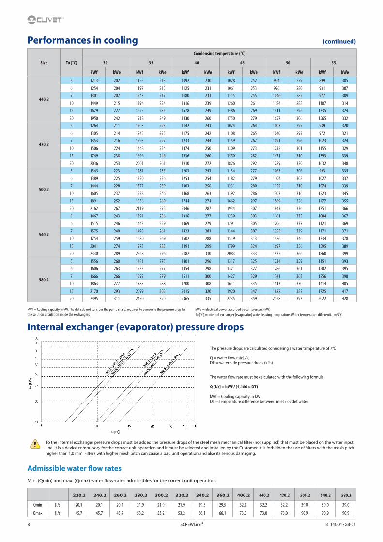
kWf = Cooling capacity in kW. The data do not consider the pump share, required to overcome the pressure drop for the solution circulation inside the exchangerskWe = Electrical power absorbed by compressors (kW)To (°C) = internal exchanger (evaporator) water leaving temperature. Water temperature differential = 5°C
kWf = Cooling capacity in kW. The data do not consider the pump share, required to overcome the pressure drop for the solution circulation inside the exchangers
kWe = Electrical power absorbed by compressors (kW)To (°C) = internal exchanger (evaporator) water leaving temperature. Water temperature differential = 5°C
Internal exchanger (evaporator) pressure drops
To the internal exchanger pressure drops must be added the pressure drops of the steel mesh mechanical filter (not supplied) that must be placed on the water input line. It is a device compulsory for the correct unit operation and it must be selected and installed by the Customer. It is forbidden the use of filters with the mesh pitch higher than 1,0 mm. Filters with higher mesh pitch can cause a bad unit operation and also its serious damaging.
Admissible water flow ratesMin. (Qmin) and max. (Qmax) water flow-rates admissibles for the correct unit operation.
The pressure drops are calculated considering a water temperature of 7°C
Q = water flow rate[l/s]DP = water side pressure drops (kPa)
The water flow rate must be calculated with the following formula
Q [l/s] = kWf / (4,186 x DT)
kWf = Cooling capacity in kWDT = Temperature difference between inlet / outlet water
Performances in cooling (continued)
BT14G017GB-01 SCREWLine³ 9
Minimum system water contentFor a proper functioning of the unit a minimum water content has to the provided to the system, using the formula:
Minimum water content [l] = 7 x kWf (air conditioning application) = 14 x kWf (application with low outdoor temperature or low loads required))
kWf = Nominal cooling capacity unit
Volume calculated does not consider internal heat exchanger (evaporator) water content.
Sound levelsStandard acoustic configuration (ST)
Size
Sound power level (dB) Sound power level
Sound pressure
levelOctave band (Hz)
63 125 250 500 1000 2000 4000 8000 dB(A) dB(A)
220.2 94 88 93 84 92 84 73 62 94 74
240.2 94 88 92 85 92 85 76 69 94 74
260.2 95 87 91 85 94 91 81 70 96 77
280.2 95 86 91 86 96 94 83 71 99 79
300.2 95 86 91 86 96 94 83 71 99 79
320.2 95 86 91 86 96 94 83 72 99 79
340.2 95 86 92 86 97 95 84 72 100 80
360.2 96 87 94 88 98 96 85 73 101 82
400.2 96 87 96 86 100 94 83 71 102 82
440.2 80 79 96 103 100 89 76 71 103 84
470.2 81 80 96 102 101 92 79 72 104 84
500.2 82 81 97 96 102 94 81 72 104 84
540.2 82 80 100 96 104 92 81 72 105 85
580.2 83 83 97 99 104 94 81 72 105 85
Acoustic configuration: Super-silenced (EN)
Size
Sound power level (dB) Sound power level
Sound pressure
levelOctave band (Hz)
63 125 250 500 1000 2000 4000 8000 dB(A) dB(A)
220.2 90 83 88 79 86 78 67 55 88 69
240.2 90 83 87 80 86 79 70 62 88 69
260.2 91 82 86 80 88 85 75 63 91 71
280.2 91 81 86 81 90 88 77 64 93 73
300.2 91 81 86 81 90 88 77 64 93 73
320.2 91 81 86 81 90 88 77 65 93 74
340.2 91 81 87 81 91 89 78 65 94 74
360.2 92 82 89 83 92 90 79 66 95 76
400.2 92 82 91 81 94 88 77 64 96 76
440.2 76 74 91 98 94 83 71 64 98 78
470.2 78 76 92 97 96 86 73 65 98 79
500.2 78 76 92 91 97 88 75 65 98 78
540.2 78 75 96 91 98 86 75 65 99 79
580.2 79 78 92 94 98 88 75 65 99 79
Sound levels refer to full load units, in test nominal conditions. The sound pressure level refers to 1 m. from the unit outer surface operating in open field. Measurements are carried out according to the UNI EN ISO 9614-2 standard, in compliance with the EUROVENT 8/1 certification.
Data referred to the following conditions:- internal exchanger water = 12/7°C- external exchanger water = 30/35°C
10 SCREWLine³ BT14G017GB-01
Correction factors for glycol useInternal exchanger (evaporator)
Data referred to the following conditions:- internal exchanger water = 12/7 °C
- condensing temperature = 45°CThe refrigerant charge above indicated is referred only to the evaporator unit
Max equivalent lengths for pipes to remote condenserSize 220.2 240.2 260.2 280.2 300.2 320.2 340.2 360.2 400.2 440.2 470.2 500.2 540.2 580.2
Difference in height - Max equivalent length of the supply and liquis pipes
0 [m] 35 30 30 40 40 40 40 40 38 40 39 39 33 29
2,5 [m] 35 30 30 40 40 40 40 40 38 40 37 37 31 28
5 [m] 35 30 30 40 38 38 38 40 38 40 36 36 30 26
7,5 [m] 35 30 30 40 36 36 36 40 38 40 34 34 29 25
10 [m] 35 30 30 40 35 35 35 40 38 39 33 33 27 24
R-134a refrigerant for each line meter [kg/m] 3,27 3,27 4,16 5,04 5,04 5,04 5,14 5,23 5,23 7,22 7,22 7,22 7,22 7,22
Values of the max. allowed equivalent length and refrigerant for each line meter considered for pipes with the same diameters indicated in the ‘General technical data’ table and in the Dimensional drawing section. These values are purely indicatives and, anyway, valid if pipes and their weld joints are correctly operating and realized, and if no leak is present. Data referred to the following conditions:- internal exchanger water = 12/7 °C - condensing temperature = 45°CThe values indicated supply an equivalent pressure drop within the following max. values:
• 1°C on the supply line to the remote condenser• 0.5°C on the liquid line to the remote condenserThe difference in height is referred to the remote condenser condition in an higher position than the evaporator unit.Attention. To take all countermeasures to avoid liquid hammers to the compressor and to ensure a correct oil return to the compressor, etc., such as sloping lines, installing traps, insulation, etc., refer to the standard and correct design rules for refrigerant lines; the manufacturer CLIVET declines all responsibilities for these.
Internal exchanger
DPr DPw
PED (CE) 1650 1050
DPr = Maximum operating pressure on refrigerant side in kPa DPw = Maximum operating pressure on water side in kPa
BT14G017GB-01 SCREWLine³ 11
Accessories
PFCP - Power-factor capacitorsThe component is necessary to lower the phase difference between current and voltage in the electromagnetic components of the unit (e.g. asynchronous motors). The component allows to put the cosfi power factor to values on average higher than 0.9, reducing the network reactive power. This often leads to an economic benefit which the energy provider grants to the final user.
The device is installed and wired built-in the unit.
CMSC9 - Serial communication module for Modbus supervisorThis enables the serial connection of the supervision system, using Modbus as the communication protocol. It enables access to the complete list of operational variables, commands and alarms. Using this accessory every unit can dialogue with the main supervision systems.
The device is installed and wired built-in the unit.
The total length of each serial line do not exceed 1000 meters and the line must be connected in bus typology (in/out)
CMSC10 - Serial communication module for LonWorks supervisorThis enables the serial connection of the supervision system which uses the LonWorks communication protocol. It enables access to a list of operating variables, commands and alarms which comply with the Echelon® standard.
The device is installed and wired built-in the unit.
The configuration and management activities for the LonWorks networks are the responsibility of the client.
LonWorks technology uses the LonTalk® protocol for communicating between the network nodes. Contact the service supplier for further information.
The total length of each serial line do not exceed 1000 meters and the line must be connected in bus typology (in/out)
CMSC11 - Serial communication module for BACnet-IP supervisorAllows the serial connection to supervision systems by using BACnet-IP as a communication protocol. It allows the access to the entire list of operating variables, controls and alarms. With this accessory every unit can communicate with the main supervision systems.
The device is installed and wired built-in the unit.
The configuration and management activities for the BACnet networks are the responsibility of the client.
The total length of each serial line do not exceed 1000 meters and the line must be connected in bus typology (in/out)
ECS - ECOSHARE function for the automatic management of a group of unitsThe device allows automatic management of units that operate on the same hydraulic circuit, by creating a local communication network.
There are two control modes that can be set via a parameter during the activation stage. They both distribute the heat load on the available units by following the distribution logic to benefit from efficiency levels at part load.
Moreover:
Mode 1 - it keeps all the pumps active
Mode 2 - it activates only the pumps of the unit required to operate
The device allows for rotation based on the criterion of minimum wear and management of units in stand-by. There are various unit sizes. Every unit must be fitted with the ECOSHARE feature. The set of units is controlled by a Master unit.
The local network can be extended up to 7 units (1 Master and 6 Slave).
The unit supplied with this device can also be equipped at the same time with the RCMRX option and one of the CMSC9 / CMSC10 / CMSC11 options.
12 SCREWLine³ BT14G017GB-01
CBS - Compressor magnetothermic circuit breakersThe magnetothermic circuit breakers are inserted instead of the fuses for the protection against the short circuit and overload. In case of intervention they do not have to be replaced, as it happens with fuses.
SFSTR2 - Progressive compressor start-up deviceThis option is also called ‘Soft starter’. Electronic device that automatically and gradually starts the compressors, thereby reducing the current peak generated in star-triangle start-ups and therefore reduces the mechanical stress on the motor and the electrodynamic stress on the power cables and on the mains.
The device is installed and wired built-in the unit.
Check availability and compatibility of ‘SFSTR2 - Progressive compressor start-up device’ with the other accessories in the “Option compatibility” table.
CONTA2 - Energy meterAllows to display and record the unit’s main electrical parameters. The data can be displayed with the user interface on the unit or via the supervisor through the specific protocol variables.
It is possible to control:
- voltage (V),
- absorbed current (A),
- frequency (Hz),
- cosfi,
- power input (KW),
- absorbed energy (KWh),
- harmonic components (%).
The device is installed and wired built-in the unit.
Only the following parameters are available on the LonWorks protocol: power input (kW) and absorbed energy (kWh)
SCP4 - Set-point compensation with 0-10 V signalThis device enables the set-point to be varied which is pre-set using an external 0÷10 V signal.
The device is installed and wired built-in the unit.
SPC1 - Set-point compensation with 4-20mA signalThis device enables the set-point to be varied which is pre-set using an external 4-20mA signal.
The device is installed and wired built-in the unit.
(-----) INPUT CAPACITY WITHOUT THE SFSTR2 OPTION(___) INPUT CAPACITY WITH THE SFSTR2 OPTION
BT14G017GB-01 SCREWLine³ 13
SPC2 - Set-point compensation with outdoor air temperature probeThis device enables the set-point to be varied automatically which is pre-set depending on the outdoor air temperature. This device enables the liquid flow temperature to be obtained, which varies depending on external conditions, enabling energy savings throughout the entire system.
The device is installed and wired built-in the unit.
The device includes a probe controlled remotely from outside to measure the outdoor air temperature. (installation to be carried out by the customer). The connection cable length is 16 m.
Accessories separately supplied
RCMRX - Remote control via microprocessor remote controlThis option allows to have full control over all the unit functions from a remote position.
It can be easily installed on the wall and has the same aspect and functions of the user interface on the unit.
All device functions can be repeated with a normal portable PC connected to the unit with an Ethernet cable and equipped with an internet navigation browser.
The device must be installed on the wall with suitable plugs and connected to the unit (installation and wiring to be conducted by the Customer). Maximum remote control distance 350 m without auxiliary power supply. For distances greater than 350 m and in any case less than 700 m it is necessary to install the ‘PSX - Mains power unit’ accessory.
Data and power supply serial connection cable n.1 twisted and shielded pair. Diameter of the individual conductor 0.8 mm.
PSX - Mains power supply unitThe device allows the unit and the remote control to communicate with the user interface even when the serial line is longer than 350m.
It must be connected to the serial line at a distance of 350m from the unit and allows to extend the length to 700m maximum in total. The device requires an external power supply at 230V AC.
Power supply at 230V AC provided by Customer
AMRX - Rubber anti-vibrating dampersThe rubber antivibration mounts must be fixed to designated housings on the support stringers and are used to dampen vibrations produced by the machine, thereby reducing the noise transmitted to the support structures.
14 SCREWLine³ BT14G017GB-01
Dimensional Drawing
Size 220.2-280.2 Acoustic configuration: Standard (ST)
SizeST-EXC
220.2 240.2 260.2 280.2
OD1 mm 76 76 76 76
OD2 mm 42 42 42 54
OD3 mm 76 76 76 76
OD4 mm 42 42 54 54
A - Length mm 4638 4638 4638 4638
B - Width mm 1350 1350 1350 1350
C - Height mm 1790 1790 1790 1790
Shipping weight kg 3083 3115 3190 3307
Operating weight kg 3390 3422 3497 3587
The presence of optional accessories may result in a substantial variation of the weights shown in the table
1. Compressor
2. Internal exchanger (evaporator)
3. Liquid receiver
4. Discharge line C1
5. Discharge line C2
6. Liquid line C1
7. Liquid line C2
8. Antivibration mount fixing holes Ø 25mm
9. Lifting bars
10. Electrical panel
11. Power input
12. Minimum space for maintenance.
BT14G017GB-01 SCREWLine³ 15
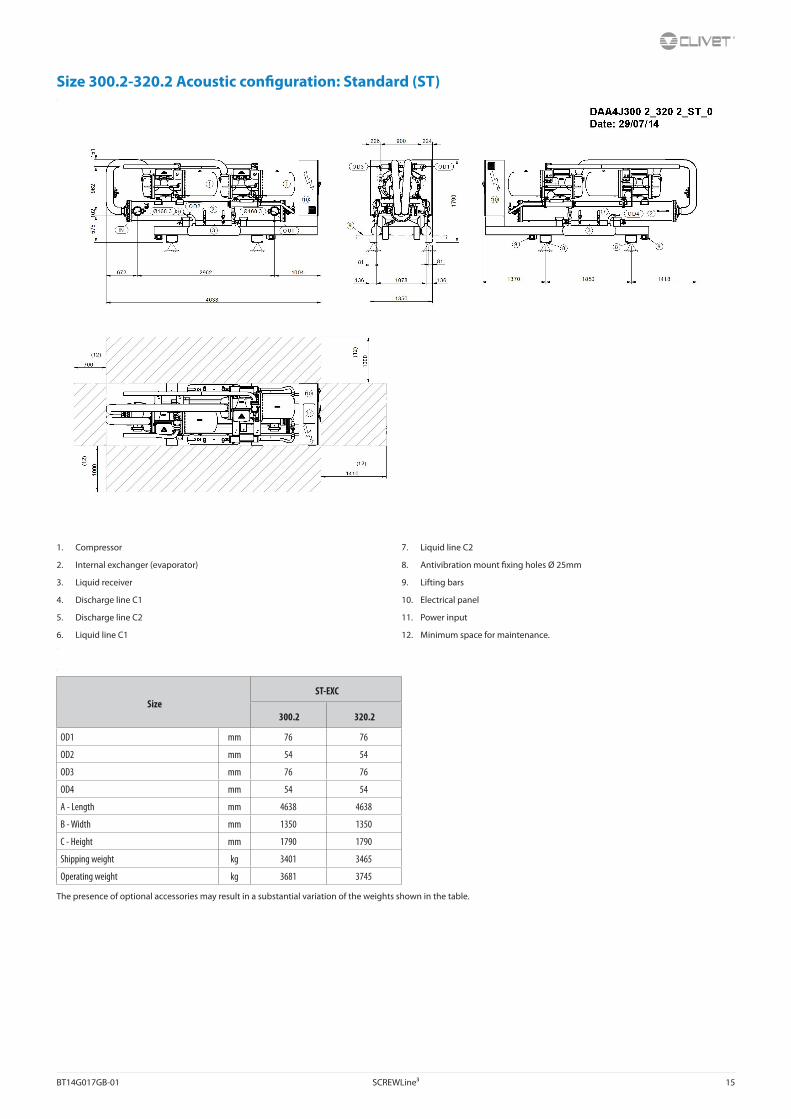
Size 300.2-320.2 Acoustic configuration: Standard (ST) Compressors Internal exchanger (evaporator) External exchanger (condenser) Internal exchanger water inletinternal exchanger water outlet External exchanger water inlet external exchanger water outlet Antivibration fixing holes Ø 25mmLifting eyeboltElectrical panel Power input Minimum dimension for Maintenance
A - LengthB - DeepthC - HeightOperating weightShipping weight
Compressors Internal exchanger (evaporator)
External exchanger (condenser) Internal exchanger water inletinternal exchanger water outlet External exchanger water inlet external exchanger water outlet Antivibration fixing holes Ø 25mmLifting eyeboltElectrical panel Power input Minimum dimension for Maintenance
A - Length
- DeepthC - HeightOperating weightShipping weight
Compressors Internal exchanger (evaporator) External exchanger (condenser) Internal exchanger water inletinternal exchanger water outlet External exchanger water inlet external exchanger water outlet Antivibration fixing holes Ø 25mmLifting eyeboltElectrical panel Power input Minimum dimension for Maintenance
A - LengthB - DeepthC - HeightOperating weightShipping weight
SizeST-EXC
300.2 320.2
OD1 mm 76 76
OD2 mm 54 54
OD3 mm 76 76
OD4 mm 54 54
A - Length mm 4638 4638
B - Width mm 1350 1350
C - Height mm 1790 1790
Shipping weight kg 3401 3465
Operating weight kg 3681 3745
The presence of optional accessories may result in a substantial variation of the weights shown in the table.
1. Compressor
2. Internal exchanger (evaporator)
3. Liquid receiver
4. Discharge line C1
5. Discharge line C2
6. Liquid line C1
7. Liquid line C2
8. Antivibration mount fixing holes Ø 25mm
9. Lifting bars
10. Electrical panel
11. Power input
12. Minimum space for maintenance.
16 SCREWLine³ BT14G017GB-01
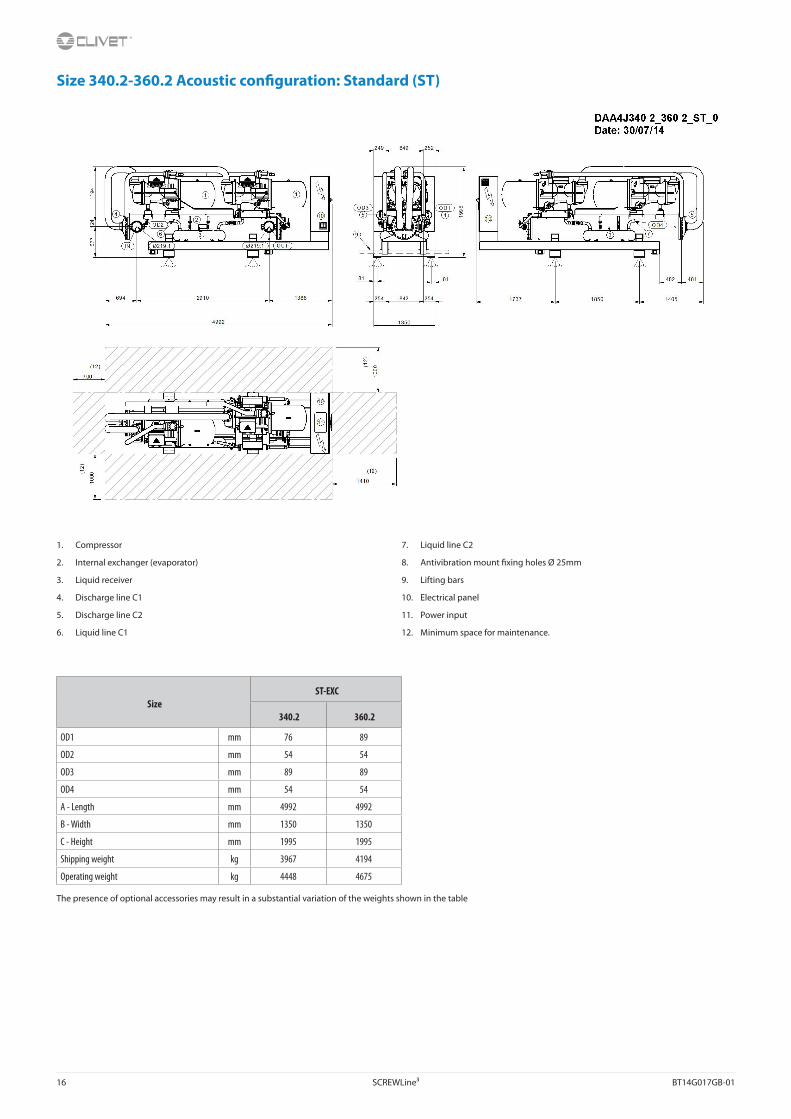
Size 340.2-360.2 Acoustic configuration: Standard (ST)
SizeST-EXC
340.2 360.2
OD1 mm 76 89
OD2 mm 54 54
OD3 mm 89 89
OD4 mm 54 54
A - Length mm 4992 4992
B - Width mm 1350 1350
C - Height mm 1995 1995
Shipping weight kg 3967 4194
Operating weight kg 4448 4675
The presence of optional accessories may result in a substantial variation of the weights shown in the table
1. Compressor
2. Internal exchanger (evaporator)
3. Liquid receiver
4. Discharge line C1
5. Discharge line C2
6. Liquid line C1
7. Liquid line C2
8. Antivibration mount fixing holes Ø 25mm
9. Lifting bars
10. Electrical panel
11. Power input
12. Minimum space for maintenance.
BT14G017GB-01 SCREWLine³ 17
Size 400.2-470.2 Acoustic configuration: Standard (ST)
SizeST-EXC
400.2 440.2 470.2
OD1 mm 89 89 89
OD2 mm 54 64 64
OD3 mm 89 89 89
OD4 mm 54 64 64
A - Length mm 5006 5006 5006
B - Width mm 1350 1350 1350
C - Height mm 2010 2010 2010
Shipping weight kg 4282 4303 4351
Operating weight kg 4763 4784 4832
The presence of optional accessories may result in a substantial variation of the weights shown in the table
1. Compressor
2. Internal exchanger (evaporator)
3. Liquid receiver
4. Discharge line C1
5. Discharge line C2
6. Liquid line C1
7. Liquid line C2
8. Antivibration mount fixing holes Ø 25mm
9. Lifting bars
10. Electrical panel
11. Power input
12. Minimum space for maintenance.
18 SCREWLine³ BT14G017GB-01
Size 500.2-580.2 Acoustic configuration: Standard (ST)
SizeST-EXC
500.2 540.2 580.2
OD1 mm 89 89 89
OD2 mm 64 64 64
OD3 mm 89 89 89
OD4 mm 64 64 64
A - Length mm 5077 5077 5077
B - Width mm 1350 1350 1350
C - Height mm 2145 2145 2145
Shipping weight kg 4763 4900 4959
Operating weight kg 5680 5817 5876
The presence of optional accessories may result in a substantial variation of the weights shown in the table