BTD-SAA-RMOA-01.06 ____________________________________________________________________ TITLE: H.323 Media Transport Over ATM ____________________________________________________________________ EDITOR: François Audet Nortel Networks mailto:[email protected]Phone: +1 408 565 5675 Fax: +1 408 565 2375 ____________________________________________________________________ DATE: 8-13 February 1999, Atlanta GA ____________________________________________________________________ ABSTRACT: This contribution contains the baseline text for the RMOA H.323 Media Transport Over ATM specification. ____________________________________________________________________ DISTRIBUTION: SAA/RMOA ____________________________________________________________________ NOTICE: This contribution has been prepared to assist the ATM Forum. This proposal is made by Nortel Networks (Northern Telecom Inc.) as a basis of discussion. This contribution should not be construed as a binding proposal on Nortel Networks. Specifically, Nortel Networks reserves the right to amend or modify the statements contained herein. ____________________________________________________________________
NOTICE: This contribution has been prepared to assist the ATM Forum.This proposal is made by Nortel Networks (Northern Telecom Inc.)as a basis of discussion. This contribution should not be construedas a binding proposal on Nortel Networks. Specifically, NortelNetworks reserves the right to amend or modify the statementscontained herein.
The information in this publication is believed to be accurate as of its publication date. Such information is subject tochange without notice and The ATM Forum is not responsible for any errors. The ATM Forum does not assume anyresponsibility to update or correct any information in this publication. Notwithstanding anything to the contrary,neither The ATM Forum nor the publisher make any representation or warranty, expressed or implied, concerning thecompleteness, accuracy, or applicability of any information contained in this publication. No liability of any kindshall be assumed by The ATM Forum or the publisher as a result of reliance upon any information contained in thispublication.
The receipt or any use of this document or its contents does not in any way create by implication or otherwise:
• Any express or implied license or right to or under any ATM Forum member company's patent, copyright,trademark or trade secret rights which are or may be associated with the ideas, techniques, concepts orexpressions contained herein; nor
• Any warranty or representation that any ATM Forum member companies will announce any product(s) and/orservice(s) related thereto, or if such announcements are made, that such announced product(s) and/or service(s)embody any or all of the ideas, technologies, or concepts contained herein; nor
• Any form of relationship between any ATM Forum member companies and the recipient or user of thisdocument.
Implementation or use of specific ATM standards or recommendations and ATM Forum specifications will bevoluntary, and no company shall agree or be obliged to implement them by virtue of participation in The ATMForum.
The ATM Forum is a non-profit international organization accelerating industry cooperation on ATM technology. The ATM Forum does not, expressly or otherwise, endorse or promote any specific products or services.
NOTE: The user's attention is called to the possibility that implementation of the ATM interoperability specificationcontained herein may require use of an invention covered by patent rights held by ATM Forum Member companies orothers. By publication of this ATM interoperability specification, no position is taken by The ATM Forum withrespect to validity of any patent claims or of any patent rights related thereto or the ability to obtain the license to usesuch rights. ATM Forum Member companies agree to grant licenses under the relevant patents they own onreasonable and nondiscriminatory terms and conditions to applicants desiring to obtain such a license. For additionalinformation contact:
The ATM ForumWorldwide Headquarters2570 West El Camino Real, Suite 304Mountain View, CA 94040-1313Tel: +1 650 949 6700Fax: +1 650 949 6705
A C K N O W L E D G M E N T S
Preparation of a Specification of this kind requires a concerted effort on the part of many individuals. The followingindividuals (names listed alphabetically), among others, provided written contributions and devoted valuable time towardsthe development of this Specification.
Marek Kotelba Andrew MalisCarlos Pazos K.K. RamakrishnanJoo Myoung Seok Curtis SillerDoug Young Suh
François Audet, Editor
Ameneh Zahir, Chair of ATM Forum SAA/RMOA Working Group
Bahman Mobassser, Chair of ATM Forum SAA Working Group
1.1 Purpose and scope......................................................................................................................................................1
1.3 Abbreviations and acronyms .....................................................................................................................................2
1.5 Service requirements ..................................................................................................................................................4
2 Call and connection control ........................................................................................................................................7
2.2 Termination of media streams at the gateways .......................................................................................................13
2.3 Selecting the Traffic Descriptors .............................................................................................................................14
3.2 RTP header compression format on ATM..............................................................................................................18
4.1 AAL2 trunking (I.366.2 and BTD-VTOA-LLTAAT2-00.07) ..............................................................................25
4.2 VTOA to the Desktop (af-vtoa-0083) .....................................................................................................................25
4.3 H.310 and af-saa-0049.001 (Native ATM).............................................................................................................26
4.4 H.321 (H.320 emulation over ATM) ......................................................................................................................26
Annex A Guidelines for choosing voice packet sizes ............................................................................................27
Annex B Using ATM as an access link to carry compressed RTP/UDP/IP media stream transport............30
Annex C Guidelines for video packetization .........................................................................................................34
H.323 Media Transport Over ATM BTD-SAA-RMOA-01.06
ATM Forum Technical Committee page 1
1 Introduction
1.1 Purpose and scope
This document specifies the ATM Forum’s implementation agreement for Real-time Multimedia Over ATM serviceincluding telephony, video-conferencing and distance learning based on the exchange of audio, video, data. It describesthe access to an ATM network using H.323. The H.323 terminal can be on a variety of network technologies, includingnon-native ATM IP-based (Ethernet, etc.), and native ATM.
1.2 References
1.2.1 Normative
[1] ATM Forum Technical Committee, af-sig-0061.000, ATM User-Network Interface (UNI) Signalling SpecificationVersion 4.0, June 1996
[2] ITU-T G.711-1988, Pulse code modulation (PCM) of voice frequencies
[3] ITU-T Recommendation H.246-1998, Interworking of H.Series multimedia terminals with H.Series multimediaterminals and voice terminals on GSTN and ISDN
[4] ITU-T Recommendation H.225.0-1998, Media stream packetization and synchronization for visual telephonesystems on non-guaranteed quality of service LANs
[5] ITU-T Recommendation H.245-1998, Control protocol for multimedia communications
[6] ITU-T Recommendation H.323-1998, Packet based multimedia communications systems
[26] IETF RFC 1889, RTP: A Transport Protocol for Real-Time Applications, January 1996, ftp://ftp.isi.edu/in-notes/rfc1889.txt
[27] IETF RFC 1890, RTP Profile for Audio and Video Conferences with Minimal Control, January 1996,ftp://ftp.isi.edu/in-notes/rfc1890.txt
[28] IETF Internet draft, Compressing IP/UDP/RTP Headers for Low-Speed Serial Links, ftp://ietf.org/internet-drafts/draft-ietf-avt-crtp-05.txt, Casner, Jacobson
[29] IETF Internet Draft, IP Header Compression, ftp://ietf.org/internet-drafts/draft-degermark-ipv6-hc-08.txt,Degermark, Nordgren, Pink
[30] IETF Internet Draft, IP Header Compression over PPP, ftp://ietf.org/internet-drafts/draft-engan-ip-compress-02.txt, Engan, Casner, Bormann
1.3 Abbreviations and acronyms
AAL ATM Adaptation LayerATM Asynchronous Transfer ModeAPDU Application Protocol Data UnitC/D Compressor/DecompressorCLP Cell Loss PriorityCPCS Common Part Convergence SublayerCPCS-PDU CPCS Protocol Data UnitCPCS-SDU CPCS Service Data UnitCPCS-UU CPCS User-to-User IndicationCPI Common Part IndicatorCRC Cyclic Redundancy CheckCSRC Contributing SourceIP Internet ProtocolISDN Integrated Services Digital NetworkISO International Organization for Standardization
H.323 Media Transport Over ATM BTD-SAA-RMOA-01.06
ATM Forum Technical Committee page 3
ITU-T International Telecommunication Union - Telecommunication Standardization SectorLANE LAN EmulationMGC Media Gateway ControllerMG Media GatewayMTU Maximum Transmission UnitOUI Organizational Unique IdentifierPDU Protocol Data UnitPCM Pulse Code ModulationPNNI Private Network-Network InterfacePPP Point-to-Point ProtocolPT Payload TypeRAS Registration, Administration and StatusRTCP Real Time Control ProtocolRTP Real Time ProtocolSCN Switched Circuit NetworkSSCS Service Specific Convergence SublayerSSRC Synchronization SourceSVC Switched Virtual ConnectionTCP Transmission Control ProtocolUDP User Datagram ProtocolUNI User-Network InterfaceVC Virtual ConnectionVCI Virtual Channel IdentifierVPI Virtual Path IdentifierVTOA Voice and Telephony Over ATM
1.4 Reference configuration
This specification makes use of H.323-to-H.323 gateways to interwork between ATM and non-ATM IP networks asshown in Figure 1.
ATMBackbonenetwork
H.323Non-ATMIP network
Gateway H.323 Non-ATMIP network
Gateway
Figure 1 Location of the Gateway
A gateway can be functionally decomposed in 3 as illustrated in Figure 2.
1. Media Gateway
The Media Gateway provides the media mapping and/or transcoding functions. It converts between the RTP/UDP/IPmedia stream on the non-ATM network and the compressed RTP media stream over an ATM SVC.
2. Media Gateway Controller
The Media Gateway Controller includes H.323 control, i.e., H.225.0 and H.245. Since the gateway is between twoH.323 systems using H.225.0/H.245, its functionality is quite simple.
BTD-SAA-RMOA-01.06 H.323 Media Transport Over ATM
page 4 ATM Forum Technical Committee
3. ATM Signalling
The ATM Signalling component is responsible for setting up SVCs to transport the RTP media stream on the ATMnetwork.
Gateway
Media Gateway Controller (MGC)
Media Gateway (MG)
Compressor/Decompressor (C/D)
H.225.0/H.245
ATM Signalling (SIG)
Figure 2 Functional decomposition of the Gateway
For the purpose of this specification, the Media Gateway, the Media Gateway Controller and the ATM Signallingcomponent are co-located. Physical separation of the Media Gateway, the Media Gateway Controller and the ATMSignalling component is possible, but considered to be outside the scope of this specification and could require additionalprotocols between the decomposed components of the gateway. The information provided by the H.225.0/H.245 protocolto the Media Gateway Controller is used by the ATM Signalling component to set up the SVCs. This process is further explained in section 2.
Figure 3 illustrates how the different functions of the gateway relate to each other in the overall reference configuration.The H.323 control traffic (H.245/H.225.0) is terminated in the Media Gateway Controller, while the media streams areprocessed by the C/D function in the Media Gateway. The compression mechanism is described in section 3.The ATMSignalling component is responsible for the establishment and termination of a SVC that carries media traffic.
Gateway
MG
SIG
MGCcontrol
H.323Non-ATMIP network
ATMBackbonenetwork
Gateway
MG
SIG
MGCcontrol
H.323 Non-ATMIP network
Figure 3 Overall reference configuration
1.5 Service requirements
A variety of devices can use H.323, under a variety of service configurations and network technologies.
The H.323 control information is transported using an IP over ATM method (e.g., RFC 1483, LANE).
The H.323 media stream information can be transported in an ATM network using three different mechanisms. Each ofthese mechanisms uses a different protocol stack for the media stream. This specification addresses these three differentmechanisms to transport media streams over ATM, as well as the interworking between them:
H.323 Media Transport Over ATM BTD-SAA-RMOA-01.06
ATM Forum Technical Committee page 5
• IP over ATM media stream transport (H.323),
• RTP over ATM media stream transport (H.323 Annex C),
• Compressed RTP over ATM media stream transport.
Some ATM H.323 terminals may operate in more than one mode of operation. As specified in Annex C/H.323, an RTPover ATM media stream transport terminal has to also be able to operate as an IP over ATM media stream transportterminal.
Annex A provides guidelines on choosing voice packet sizes.
Annex B describes a method for compressing RTP/UDP/IP headers to be used while accessing an IP network throughan ATM link (e.g.: access through DSL).
Annex C provides guidelines for video packetization.
1.5.1 IP over ATM media stream transport (H.323)
H.323 in the basic mode of operation uses an IP over ATM method to carry the media stream over ATM instead of usinga separate SVC. It therefore does not utilize the inherent Quality of Service capabilities of ATM. It is also very bandwidthinefficient because of the significant overhead introduced by using RTP (at least 12 octets), UDP (8 octets) and IP (at least20 octets). The multiprotocol encapsulation header (RFC 1483) adds another 8 octets. Note that other methods such asLANE also add a header with its own overhead. This inefficiency is more crucial when the multimedia session is voiceonly because of the very small size of the voice packets.
Media stream
header
header
RTP
UDP
headerIP
≥ 12 octets
≥ 20 octets
8 octets
trailerAAL5 CPCS-PDU
ATM h h h h
8 octets
5
Media stream
RTP
UDP
IP
Multiprotocol
encapsulation
AAL5
ATM
h h
Multiprotocolencapsulation header
8 octets
Figure 4 IP over ATM media stream transport
BTD-SAA-RMOA-01.06 H.323 Media Transport Over ATM
page 6 ATM Forum Technical Committee
1.5.2 RTP over ATM media stream transport (H.323/Annex C)
H.323 Annex C uses AAL5 directly to transport media streams on RTP. It is an improvement over the IP over ATMmethod because it sets up a SVC for the media transport enabling the use of ATM Quality of Service. While better thanfor IP over ATM media stream transport, it is still quite bandwidth inefficient (especially for voice only multimediasessions) because of the significant overhead of the RTP protocol (at least 12 octets). Annex C is intended for use bynative ATM terminals. When an native ATM terminal interoperate with a non-ATM H.323 terminal, it will not operatein Annex C mode but in an IP over ATM method or in a compressed RTP over ATM method.
Media stream
headerRTP≥ 12 octets
trailerAAL5 CPCS-PDU
ATM h h h h
8 octets
5
Media stream
RTP
AAL5
ATM
h
Figure 5 RTP over ATM media stream transport
1.5.3 Compressed RTP over ATM media stream transport
The goal of this specification is to describe how to perform header compression of the RTP/UDP/IP protocols over AAL5.
Two methods are proposed:
1. Terminated the UDP/IP protocol in the Media Gateway, compress the RTP header and carry the resulting packetdirectly over AAL5. This method is described in the main body of this specification.
2. Compress the RTP/UDP/IP headers as a whole and to carry the resulting packet over AAL5. This method is describedin Annex B.
The method described in the main body of the specification terminates the UDP/IP protocols on the media gateway,removing the need to transport these headers end-to-end. As such, it is appropriate to elide the IP and UDP headers, andcarry the media stream with compressed or uncompressed RTP headers, as appropriate. The technique of headercompression then becomes one of compressing just the RTP headers. The call and connection control for this H.323Gateway to H.323 Gateway case that allows termination of media streams at the gateway is described in section 2. Thecompression of RTP headers is described in section 3.
Media stream
RTP
Compressor/
Decompressor
AAL5
ATM
Figure 6 Compressed RTP over ATM media stream transport
H.323 Media Transport Over ATM BTD-SAA-RMOA-01.06
ATM Forum Technical Committee page 7
2 Call and connection control
The reference architecture for establishment of the H.323 call using media stream transport over ATM is shown in Figure7. For simplicity, only the case where both terminals are on non-ATM IP networks are shown. If one or more of theterminals were native ATM terminals, the gateway and terminal functionality would be merged. If the two terminals arenative ATM terminals, they can use the H.323 Annex C procedures and compress the RTP flow according to thecommpression method proposed in section 3.
• With respect to control traffic between the endpoints, each of the gateway to the ATM backbone network serves asan H.323-to-H.323 gateway.
• With respect to media streams between the endpoints, each of the gateway terminates the media stream for the nearendpoint and acts as a compressor/decompressor for the RTP media stream.
Figure 7 is meant as an example of two endpoints communication through two ATM gateways. It is however necessarythat the calls are terminated at Gateway X and Gateway Y at the edges of the ATM network.
ATMBackbonenetwork
SVCsetup
H.225.0H.245
SIG
control
endpointA
Non-ATMIP network
GatekeeperA
H.225.0H.245
Q.2
931
Gw X
MG
MGC
GatekeeperC
SIG
control
endpointB
Non-ATMIP network
H.225.0H.245
Q.2
931
Gw Y
MG
MGC
GatekeeperB
Figure 7 Architecture for call control
2.1 SVC Setup
SVCs are set up for the transport of RTP media streams based on the H.245 control messages exchanged by the endpointsand the access devices. In the ATM network, the corresponding control messages are sent between the access devicesusing an IP over ATM method.
SVCs for media streams are established at the edges of the ATM network, i.e., at the signalling gateway. H.323 has noconcept of the reverse direction of a unidirectional logical channel. However, an important characteristic of point-to-pointATM VCs is that they are inherently bi-directional. The use of both directions of an ATM VC is therefore desirable.Otherwise, the audio and video streams will each need to be sent on two different VC's, one for each direction.
Outside of the ATM network, the logical channels are set-up uni-directionally. The MGC can open the ATM mediastreams as bi-directional logical channels when possible. This reduces the number of AAL 5 VCs to two in typicalsituations, one VC each for audio and for video, or to one for a voice-only call.
The following sections describe SVC setup based on control signalling, with and without the fast connect procedures.
BTD-SAA-RMOA-01.06 H.323 Media Transport Over ATM
page 8 ATM Forum Technical Committee
2.1.1 SVC setup with fast connect
Fast connect is the preferred procedure for simple telephony calls. Fast connect provides faster call setup and solves someinteroperability problems. It also simplifies the SVC setup process.
Endpoint A initiates the call through an ARQ/ACF sequence exchange with the gatekeeper (Gatekeeper A) it is registeredwith, providing Endpoint B alias address. Gatekeeper A has Gateway X registered in its zone as the gateway serving thealias address of Endpoint B and returns that gateway’s call signaling channel address in its ACF message to Endpoint A;such registration may have been manually configured. Endpoint A then sends a SETUP message to the call signalingaddress of Gateway X, providing Endpoint B’s address. Therefore, from Endpoint A’s perspective, the call proceeds asif the call was made to a local terminal on its non-ATM network. The SETUP message include the fastStart elementconsisting of a proposed choice of OpenLogicalChannel elements. See section 8.7.1/H.323. The OpenLogicalChannelcontains the transport address for the reverse RTCP channel to Gateway X.
On receiving the SETUP message, Gateway X initiates an ARQ/ACF sequence with Gatekeeper A to determine if it canaccept the call. Gateway X may also send a CALL PROCEEDING message to Endpoint A so that Endpoint A does nottimeout the call prematurely. Since the call goes over the ATM network, Gateway X also initiates an ARQ/ACF sequencewith Gatekeeper B, providing Endpoint B’s address. Gatekeeper B has all the access devices registered in its zone andtherefore it knows each gateway’s coverage area. For the ARQ from Gateway X containing the alias address of EndpointB, Gatekeeper B returns the call signaling address for Gateway Y. Gateway X then sends a SETUP message (includingfastStart) to Gateway Y. The OpenLogicalChannel contains the transport address of Endpoint B.
On receiving the SETUP message, Gateway Y initiates an ARQ/ACF sequence with Gatekeeper B and optionally sendsa CALL PROCEEDING message to Gateway X. Gateway Y also initiates an ARQ/ACF sequence with Gatekeeper C,providing Endpoint B’s address. Then, Gateway Y sends a SETUP message (including fastStart) to endpoint B. Aftera successful ARQ/ACF exchange with Gatekeeper C, Endpoint B responds affirmatively to the fast connect procedureby including the fastStart element in a call control message to Gateway Y (CALL PROCEEDING, PROGRESS,ALERTING, or CONNECT) as per 8.7.1/H.323.
Gateway Y is responsible for establishing the ATM SVCs. If the logical channels indicated in the fastStart are bi-directional in nature (i.e., a pair of unidirectional channels), the gateway may set up a bi-directional SVC for the pair tosave on the number of SVCs used by the session. The SVC shall be set up upon receipt of the fastStart in the H.225.0message from endpoint B. If more than one media stream is used, the gateway sets up an SVC for each media. Since aGateway may terminate many such SVCs to other gateways, the Q.2931 SETUP message carries Gateway Y's transportaddress of the RTP media stream in the B-HLI information element (see section 2.2). This information is used by GatewayX to associate the incoming SVC call with the appropriate RTP channel. Gateway Y shall only proceed with call set upprocedures, including forwarding of the fastStart element, with Gateway X when the SVC setup is completed.
Note - CALL PROCEEDING has a local significance. When a called endpoint responds with fastStart in a CALLPROCEEDING message, a gatekeeper or gateway that forwarded the SETUP message to may already have respondedto the calling endpoint with a CALL PROCEEDING message and the fastStart would thus be lost. The gatekeeper orgateway shall pass the fastStart element in a FACILITY message. This is in accordance with H.225.0 procedures. See theImplementers Guide [9].
Figure 8 illustrates an example of setting-up a bi-directional communication for this scenario.
Endpoint B may send RTP packets before the SVC is setup, in which case the RTP packets will be delivered to EndpointA using an RTP over ATM method with no QoS of the SVC.
H.323 Media Transport Over ATM BTD-SAA-RMOA-01.06
ATM Forum Technical Committee page 9
H.225.0 SETUP (with fastStart)
non-ATMnetwork
EndpointA
EndpointB
GkA
GkB
GkC
non-ATMnetwork
H.225.0 CALL PROC.
H.225.0 CALL PROC.
ARQ/ACF
ARQ/ACF
ARQ/ACF
ARQ/ACF
ARQ/ACF
ARQ/ACF
H.225.0 CONNECTH.225.0 CONNECT
ATMnetwork
GwX
GwY
H.225.0 SETUP (with fastStart)
H.225.0 CONNECT
H.225.0 SETUP (with fastStart)
Q.2931 SETUPVC opened to carryRTP/UDP/IP mediastreams Q.2931 CONNECT
H.225.0 ALERTING (with fastStart)
H.225.0 ALERTING (with fastStart)
H.225.0 ALERTING (with fastStart)
B-to-A RTPchannel opened
A-to-B RTPchannel opened
Figure 8 SVC setup with fast connect
2.1.2 SVC setup without Fast Connect
Figure 9 shows the control messages exchanged between the H.323 entities involved in the establishment of the H.245control channel based on the architecture of Figure 7.
Endpoint A initiates the call through an ARQ/ACF sequence exchange with the gatekeeper (Gatekeeper A) it is registeredwith, providing Endpoint B alias address. Gatekeeper A has Gateway X registered in its zone as the gateway serving thealias address of Endpoint B and returns that gateway’s call signaling channel address in its ACF message to Endpoint A;such registration may have been manually configured. Endpoint A then sends a SETUP message to the call signalingaddress of Gateway X, providing Endpoint B’s address. Therefore, from Endpoint A’s perspective, the call proceeds asif the call was made to a local terminal on its non-ATM network.
On receiving the SETUP message, Gateway X initiates an ARQ/ACF sequence with Gatekeeper A to determine if it canaccept the call. Gateway X may also send a CALL PROCEEDING message to Endpoint A so that Endpoint A does nottimeout the call prematurely. Since the call goes over the ATM network, Gateway X also initiates an ARQ/ACF sequencewith Gatekeeper B, providing Endpoint B’s address. Gatekeeper B has all the access devices registered in its zone and
BTD-SAA-RMOA-01.06 H.323 Media Transport Over ATM
page 10 ATM Forum Technical Committee
therefore it knows each gateway’s coverage area. For the ARQ from Gateway X containing the alias address of EndpointB, Gatekeeper B returns the call signaling address for Gateway Y. Gateway X then sends a SETUP message to thataddress, providing Endpoint B’s address.
On receiving the SETUP message, Gateway Y initiates an ARQ/ACF sequence with Gatekeeper B and optionally sendsa CALL PROCEEDING message to Gateway X. Gateway Y also initiates an ARQ/ACF sequence with Gatekeeper C,providing Endpoint B’s address. Then, Gateway Y sends a SETUP message to endpoint B. After a successful ARQ/ACFexchange with Gatekeeper C, Endpoint B responds with a CONNECT message to Gateway Y. Gateway Y then translatesthat message into a CONNECT message to Gateway X. Gateway X, in turn, sends a CONNECT message to Endpoint A.
non-ATMnetwork
EndpointA
EndpointB
GkA
GkB
GkC
non-ATMnetwork
H.245 Control channel established
H.225.0 SETUP
H.225.0 CALL PROC.
H.225.0 CALL PROC.
ARQ/ACF
ARQ/ACF
ARQ/ACF
ARQ/ACF
ARQ/ACF
H.225.0 SETUP
ARQ/ACF
H.225.0 SETUP
H.225.0 CONNECTH.225.0 CONNECT
H.225.0 CONNECT
ATMnetwork
GwX
GwY
Figure 9 Control sequence to establish the H.245 control channel
At this point the H.245 control channel is established and the control messages are explicitly addressed to the gateways.The gateways use the information transported in the OpenLogicalChannel and OpenLogicalChannelAck messages toestablish a bi-directional SVC to carry the media stream.
The OpenLogicalChannel and OpenLogicalChannelAck are generated by the endpoints, exactly as if there were nointervening ATM network; the endpoints are not aware that ATM SVCs are set-up unless an endpoint itself is an ATMendpoint, in which case the function of the endpoint and the gateway are co-located. This approach requires nomodifications to H.323 terminals attached to the non-ATM networks.
H.323 Media Transport Over ATM BTD-SAA-RMOA-01.06
ATM Forum Technical Committee page 11
2.1.2.1 Bi-directional SVC set-up
Section 2.1.1 describes how the H.245 control channel is established through the gateways as intermediary processingpoints. Once this phase is complete, the logical channels can be opened for the transport of media streams, following theCapability Exchange and Master/Slave Exchange phases. Endpoint A sends an OpenLogicalChannel message, containingthe transport address for the reverse RTCP channel to Gateway X. (Let us call the A-to-B channel the forward channel).Gateway X receives this message and sends an OpenLogicalChannel to Gateway Y that, in turn, sends anOpenLogicalChannel message to Endpoint B.
Endpoint B then replies to Gateway Y with an OpenLogicalChannelAck message containing the transport addresses forthe forward media channel and the RTCP channel. If the reverse channel is to be opened for the reverse direction,Endpoint B also sends an OpenLogicalChannel message to Gateway Y. That message contains the same RTCP transportaddress that was sent in the OpenLogicalChannelAck message. In this way, Gateway Y knows which transport addressesto use when forwarding the media and RTCP streams to Endpoint B. Gateway Y also forwards both messages to GatewayX while providing its ATM address in OpenLogicalChannelAck message.
On arrival of the OpenLogicalChannelAck message, Gateway X sets up a bi-directional SVC using the ATM addressprovided in this message. For the forward direction, it can request the necessary bandwidth to support the voice encodingstandard selected in the OpenLogicalChannel message sent to Gateway Y. However, the OpenLogicalChannel messagefrom Gateway Y may select a different voice encoder and the establishment of an asymmetric SVC is appropriate.Therefore, Gateway X should delay the transmission of an OpenLogicalChannelAck message to Endpoint A until itreceives the OpenLogicalChannel message from Gateway Y. When this happens, Gateway X has all the informationneeded and it establishes the appropriate bi-directional SVC. However, since a gateway may terminate many such SVCsto other gateways, the Q.2931 SETUP message carries the transport address for the respective forward RTP media streamon its B-HLI element. This information is used by Gateway Y to associate the incoming SVC call with the appropriateRTP channel.
When the SVC setup is completed, Gateway X sends the delayed OpenLogicalChannelAck message to Endpoint A, thusestablishing the forward RTP media channel. The OpenLogicalChannel message is also sent to Endpoint A to open thereverse RTP media stream. Endpoint A replies with an OpenLogicalChannelAck message containing the same transportaddress used for the forward direction. When this message reaches Gateway Y, it associates the RTP transport addresswith the pre-established SVC. Finally, when this message reaches Endpoint B, the reverse RTP media channel isestablished. Figure 10 illustrates the establishment of such bi-directional SVC.
The above scenario assumes that the logical channels will be opened in both the forward and the reverse direction, whichis a typical case in the point-to-point voice call. However, to account for the logical channel not being opened in thereverse direction, Gateway X needs to set a timer upon receiving the OpenLogicalChannelAck. The value of the timeris implementation specific. If this timer expires, Gateway X proceeds to set up a unidirectional SVC for the forward mediastream (see 2.1.2.2).
There is a possibility that the OpenLogicalChannel in the reverse direction has been sufficiently delayed such that it isreceived by Gateway X after the timer expiry. In that case, Gateway Y becomes responsible for the SVC establishmentin the reverse direction. Gateway Y will have to examine the reverse traffic descriptor in the Q.2931 SETUP message fromGateway X. If this traffic descriptor is null, upon reception of the reverse OpenLogicalChannelAck from Gateway X,Gateway Y will establish the reverse SVC. Note that this message must carry the ATM address of Gateway X.
BTD-SAA-RMOA-01.06 H.323 Media Transport Over ATM
page 12 ATM Forum Technical Committee
H.245 Control channel established
Capability Exchange
Master/Slave Exchange
Q.2931 SETUPVC opened to carryRTP/UDP/IP mediastreams
Q.2931 CONNECT
ATMnetwork
non-ATMnetwork
EndpointA
EndpointB
.
.
.Endpoint A calling Endpoint B
GwY
B-to-A RTPchannel opened
A-to-B RTPchannel opened
GwX
non-ATMnetwork
OpenLogicalChannel
OpenLogicalChannel
OpenLogicalChannelAck
OpenLogicalChannelAck
Figure 10 Bi-directional SVC set-up without fast connect
2.1.2.2 Unidirectional SVC set-up
Although a bi-directional SVC setup is preferable when possible, it is necessary to have procedures to setup unidirectionalSVCs.
The gateway set ups a unidirectional SVC upon receipt of an OpenLogicalChannelAck. It shall then delay theforwarding of the OpenLogicalChannelAck to the other gateway until the SVC is set-up.
Figure 11 illustrates an example of setting-up a bi-directional communication for this scenario.
H.323 Media Transport Over ATM BTD-SAA-RMOA-01.06
ATM Forum Technical Committee page 13
B-to-A RTPchannel opened
H.245 Control channel established
Capability Exchange
Master/Slave Exchange
Q.2931 SETUPVC opened to carryRTP/UDP/IP mediastreams Q.2931 CONNECT
ATMnetwork
non-ATMnetwork
EndpointA
EndpointB
.
.
.Endpoint A calling Endpoint B
GwY
A-to-B RTPchannel opened
GwX
non-ATMnetwork
OpenLogicalChannel
OpenLogicalChannel
OpenLogicalChannelAck
OpenLogicalChannelAckQ.2931 SETUP
Q.2931 CONNECT
Figure 11 Unidirectional SVC set-up without fast connect
2.2 Termination of media streams at the gateways
The previous section describes how the interception of H.225.0/H.245 control message is used to establish SVCs for thetransport of media stream. However, this is just half of the problem. The other half leads to the media termination on thegateways, which facilitates the forwarding over the SVC. Namely, the OpenLogicalChannel andOpenLogicalChannelAck messages communicate the transport addresses used for the exchange of RTP and RTPCpackets. Then, the gateways shall use the transport addresses they receive from the endpoints in the OpenLogicalChanneland OpenLogicalChannelAck messages to forward the respective RTP/RTCP streams to the endpoints. However, thegateways shall use their own transport addresses in the OpenLogicalChannel and OpenLogicalChannelAck messagesthey generate to the endpoints and to the other gateway. Therefore, the respective RTP/RTCP flows terminate on anendpoint and on a gateway while traversing the non-ATM networks.
Endpoints A and B see the respective near switch as the actual endpoint with which a voice call has been established. Thisis what characterizes media termination on the gateway. As a result, the voice samples are embedded on packets havingIP addresses (IP_A, IP_X, etc) and UDP port numbers (#AX, #XA, etc) that reflect each Endpoint-Gatewaycommunication, as illustrated in Figure 12.
BTD-SAA-RMOA-01.06 H.323 Media Transport Over ATM
page 14 ATM Forum Technical Committee
RTP Header
RTPPayload
GatewayX
RTP Header
RTPPayload
#AX #XA
Endpoint A
IP_AIP_X
SVC for media stream
ATM Network
GatewayY
RTP Header
RTPPayload
#BY#YB
Endpoint B
IP_BIP_Y
Figure 12 Media termination on H.323 endpoints
2.3 Selecting the Traffic Descriptors
It is important to set the proper cell rate parameters in the ATM Traffic Descriptor information element. The peak cell ratecan be derived from the H.245 capabilities exchange parameters and the RTP payload format packet size. For video, themaxBitRate field can be used from the H261VideoCapability or the H263VideoCapability to determine the ATM Cellrate. For audio, the audio capability chosen implies the bit rate to be used. For example, the use of g711Ulaw64k suggeststhe use of a 64 kbit/s audio channel, while the use of g728 indicates the use of a 16 kbit/s channel. The RTP payloadformat indicates the packet size. For each packet, the subsequent AAL5 CPCS-PDU overhead and any needed paddingto meet the packetization rules, must be added. This results in an overhead bit rate that is associated with the size of thepacket and the way this packet is encapsulated in AAL5, and the frequency of this overhead from this encapsulation.
The bit rate of the data to be sent, and the packetization of the data according to the AAL packetization rules determinethe cell rate. The packetization will determine the actual number of cells that must be sent for a given data stream at a givenbit rate. See Annex A for guidelines on how to choose packet sizes for audio.
2.4 ATM Signalling
This specification uses UNI Signalling 4.0 or PNNI 1.0 to set-up SVCs for the transport of the RTP media stream. Thefollowing describes the coding of the necessary information elements.
2.4.1 Broadband low layer information
IE Parameter Value Notes
User information layer 3 protocol(octet 7)
'01011' ISO/IEC TR 9577
Additional layer 3 protocolinformation
(octets 7a, 7b, 8)
'0100 0000''1000 0000''1000 0000'
IEEE 802.1 SNAP
Additional layer 3 protocolinformation
(octets 8.1-8.3)
x'00 A0 3E' ATM Forum OUI
Additional layer 3 protocolinformation
(octets 8.4-8.5)
x'?? ??' Compressed RTP over ATM
Table 1 Broakdand Low Layer Information
H.323 Media Transport Over ATM BTD-SAA-RMOA-01.06
ATM Forum Technical Committee page 15
2.4.2 ATM Adaptation layer parameters
IE Parameter Value NotesAAL type (octet 5) '0000 0101' AAL 5Forward maximum
AAL-5 CPCS-SDU size(octets 6.1-6.2)
MTU size This value reflects thecombination of the maximum
RTP payload plus the maximumRTP(/UDP/IP) headers
Backward maximumAAL-5 CPCS-SDU size
(octets 7.1-7.2)
MTU size This value reflects thecombination of the maximum
Susceptibility to clipping Susceptible to clippingUser-plane connection
configurationpoint-to-point
Table 3 ATM Broadband bearer capability for CBR
b) Using real time VBR with CLR commitment on CLP=0+1
IE Parameter Value NotesBearer class BCOB-X
Broadband bearer capability '0010011' Real time VBR with CLRcommitment on CLP=0+1
Susceptibility to clipping Susceptible to clippingUser-plane connection
configurationpoint-to-point
Table 4 ATM Broadband bearer capability for rt-VBR with commitment on CLP = 0+1
BTD-SAA-RMOA-01.06 H.323 Media Transport Over ATM
page 16 ATM Forum Technical Committee
3 Compressed RTP media stream transport over ATM
This section describes a "real-time" AAL5 encapsulation for carrying real-time streams, such as audio and video, overATM. The encapsulation function for real-time AAL5 sits just above the AAL5 adaptation layer, and thus uses existingATM layers without modification. This allows real-time AAL5 to be deployed on existing hardware implementationswithout modification.
Many compression algorithms for real-time streams are able to manage loss without the need for retransmission. For thisreason, real-time AAL5 associates a sequence number with each AAL5 frame. This sequence number may be used todetect loss and trigger the execution of a loss concealment algorithm.
Real-time streams often need to communicate data other than the real-time samples. For example, end-end applicationinformation, such as inter-media synchronization and time stamps, must often be exchanged between end systems. Real-time AAL5 provides a framework for such an information exchange through an "extension" bit. When the extension bitis set, additional information is embedded in the AAL5 frame along with the real-time samples. This provides the desiredflexibility by allowing application specific information to be carried over the same virtual circuit as real-time samples.
Utilizing the framework provided by real-time AAL5, this section describes a method for efficiently carrying RTP packetsover an ATM network. This is done by treating an ATM virtual circuit as a point-to-point link and employingRTP(/UDP/IP) header compression. An ATM compressed RTP header is combined with real-time samples into a real-time AAL5 frame. The extension bit is set whenever an uncompressed RTP header is sent.
The goal of this method is to transport real-time data over an ATM network as efficiently as possible, recognizing thatthe real-time stream may be generated from an ATM end-system, or it may more generally be generated from a computersystem using an RTP protocol stack. This method requires little distinctive processing compared to carrying native ATMmedia streams.
The big gain in this method comes from the observation that although several fields change in every packet, the differencefrom packet to packet is often constant and therefore the second order difference is zero. By maintaining both theuncompressed header and the first order differences in the session state shared between the compressor and thedecompressor, all that must be communicated is an indication that the second order difference was zero In that case, thedecompressor can reconstruct the original header without any loss of information simply by adding the first orderdifferences to the saved uncompressed header as each compressed packet is received.
Section 1.5.2 shows that for RTP over ATM, the typical (and minimum) overhead amounts to 12 octets. Compression ofthe headers occurs at the edges of the ATM network as shown in the following figures:
RTP
C/D
AAL5
ATM End System
ATM
C/D
AAL5
ATM End SystemCompressor/De-compressor
RTP
Figure 13 Compressor/De-compressor in an ATM End System
H.323 Media Transport Over ATM BTD-SAA-RMOA-01.06
ATM Forum Technical Committee page 17
RTP
IP End System
ATM
C/D
AAL5
ATM End SystemCompressor/De-compressor
IP Network
C/D A
AL
5
RTP
RT
P
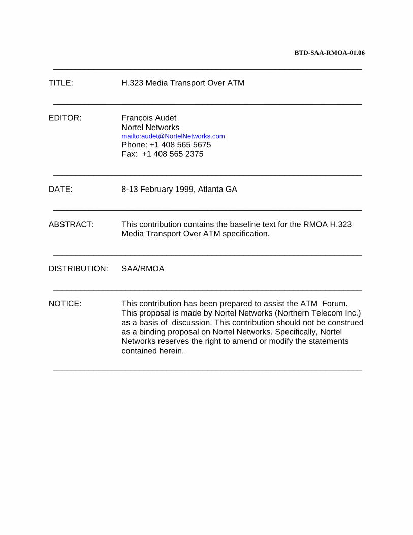
Figure 14 Compressor/De-compressor in an IP/ATM Router
ATM
Header Compressor/De-compressor
IP Network
C/D A
AL
5
C/DA
AL
5RTP
IP End System
IP Network
IP End System
RTP
RT
P
RT
P
Figure 15 Carrying Compressed RTP/IP/UDP in an ATM backbone
Section 3.1 describes real-time AAL5, and section 3.2 describes RTP(/UDP/IP) header compression format which is anapplication of real-time AAL5.
3.1 Real-time AAL5 CPCS-PDU
The format for a real-time AAL5 CPCS-PDU is shown in Figure 16. Real-time AAL5 CPCS-PDU makes use of the 8-bituser-to-user field (CPCS-UU) of I.363.5. The first bit is an "extension bit", the second bit is a control bit and the other 6bits are the sequence number. When applicable, the 6-bit sequence number is incremented with each AAL5 frameirrespective of the state of the extension bit.
The extension bit allows application specific information to be included along with real-time samples. As shown in Figure17, when the extension bit is set to 0, the real-time AAL5 payload consists of real-time samples and necessary padding.When the extension bit is set to 1, a header extension field is added to the payload before the real-time samples, as shownin Figure 18. The payload consists of the header extension field, real-time samples, and necessary padding. The formatof the header extension field is application specific. It may include headers that are included with the packet to allowsending additional information between communicating AAL entities.
BTD-SAA-RMOA-01.06 H.323 Media Transport Over ATM
page 18 ATM Forum Technical Committee
Real-time information and padding 0 X sequence # CPI length CRC
Figure 17 Real-Time AAL5 Encapsulation (Extension Bit = 0)
Real-time information and padding 1 X sequence # CPI length CRCHeader Extension
Figure 18 Real-Time AAL5 Encapsulation (Extension Bit = 1)
Note - The 6-bit sequence number does not imply that the decoder is required to buffer 64 packets.
3.2 RTP header compression format on ATM
The Internet Engineering Task Force (IETF) has been working on header compression [29], in particular on compressingthe RTP/UDP/IP headers [28] in the context of a point-to-point PPP link [30]. Since a virtual circuit in an ATM networklooks similar to a point-to-point link the same approach may be used in ATM networks. This has the advantage of notwasting ATM network bandwidth by carrying unnecessary information, and recovers a substantial part of the cell tax paidwhen carrying packets over an ATM network. This section describes carrying RTP packets in an ATM network using real-time AAL5.
For information, typical RTP, UDP and IP headers are shown in Figure 19.
The signalling architecture in section 2 allows an H.323-H.323 gateway to terminate H.323 media streams.
From the signalling a procedures of section 2, an SVC is established between the H.323-H.323 Gateways X and Y for thetransport of media stream between Endpoints A and B. A gateway then forwards the media packets received from anendpoint to the other gateway over this SVC. However, most of the IP and UDP information on packets (e.g., IP addressesand UDP port numbers) reaching a gateway has no meaning to the other Endpoint-Gateway communication and it neednot be sent. Therefore, the only pertinent information to be transferred over the SVC is the RTP header and payload, asshown in Figure 1. Header compression can then be applied only to the RTP header. For this reason, RTP-only headercompression shall be used when used over SVCs connecting two H.323-to-H.323 gateways in the core of an ATMnetwork instead of RTP/UDP/IP header compression. Since the UDP and IP layers are terminated at the gateways, IPfragments shall also be re-assembled at the gateways. For application that are delay sensitive such as voice, this shouldnot be a problem since the packets are likely to be very small.
H.323 Media Transport Over ATM BTD-SAA-RMOA-01.06
ATM Forum Technical Committee page 19
3.2.1 Definition of the call context
Even though header compression has been originally conceived for PPP links [28], it is also attractive when shipping RTPtraffic over ATM SVCs. However, the requirements on header compression on H.323-H.323 gateways are more stringentbecause a gateway has to maintain contexts, implement the signaling functionality in section 2, and route each stream overthe appropriate SVC. The use of RTP-only compression presented here reduces the memory requirements to maintain acall context. It would consist only of the last RTP header sent/received, the first order differences needed to reconstructan RTP header from a compressed packet and a sequence number space to detect packet losses.
The fields in the RTP header that may require the 1st order difference in the call context are those that can change on apacket-by-packet basis. These are the M bit, the sequence number, the time stamp, the CC count and the CSRC list.
• The M bit marks special events for the real-time application using RTP and it may change frequently; therefore theM bit for a packet need always be communicated.
• The sequence number is expected to always increase by one and this 1st order difference is not included in the callcontext.
• Since the variations on the RTP time stamp can change over the duration of a call, the 1st order difference for this fieldis included in the call context.
• Changes to the CSCR list need to be communicated explicitly, hence 1st order differences need not be maintained.Figure 20 summarizes how the compressor and the de-compressor handle each of the RTP header fields.
Possible variations acrosspackets; changes are notified.
The RTP header is the only header stored on the call context and memory requirements are further reduced by notincluding a table for the encoding of differences for each call, as suggested in [28]. Nevertheless, as part of a C/Dnegotiation phase, both C/D ends need to agree on whether to use the encoding table in [28] or an encoding restricted toonly two bytes. Since the IP and UDP layers are terminated at the gateways, the UDP checksum, when present, would beset to zero.
With these simplifications, the call context for the RTP header compression is defined as illustrated in Figure 21. Notethat the use of a generation field [28] is not considered, while the E flag is added. The E flag signals whether the encodingtable in [28] is used to encode 1st order differences.
RTP Header
First order difference for the RTP time stamp field
Sequence number value and E flag
Figure 21 Call context for RTP header compression
BTD-SAA-RMOA-01.06 H.323 Media Transport Over ATM
page 20 ATM Forum Technical Committee
Similarly to the IETF header compression approaches in [28], the RTP-only compression relies on the link layer beingable to provide an indication of the different packet formats below. All but one of these formats will carry an RTP headerextension whenever it is present in the original packet. The assumption here is that real-time applications would use theRTP header extension or UDP checksum on all packets or on none at all.
• FULL_RTP_HEADER - communicates a full RTP header to establish or synchronize the state in the de-compressorfor a call context. Unlike the full IP/UDP/RTP header compression over PPP links [28], the RTP-only compressionover SVCs does not require a context identifier (CID). Namely, in a PPP link, the C/Ds on both ends need to maintaincontext for many IP flows traversing the same link and the CIDs are used to determine the context in which a packethas to be considered. Since the SVCs are dedicated to a single one-way RTP flow, the context is defined by theVCI/VPI of the SVC over which the packets are sent. A sequence number is still needed to establish thesynchronization between the compressor and the de-compressor.
• CONTEXT_STATE – is a special packet sent from the de-compressor to the compressor indicating that the contextassociated with the SVC may have been invalidated. The compressor is expected to send the next packet as aFULL_RTP_HEADER packet. Since this packet type is used for error recovery (it carries no payload), it never carriesan RTP header extension.
• DELTA_RTP - communicates the new 1st order differences for the RTP header fields indicated since they incurreda non-zero 2nd order difference. The header for this type of packet contains a 4bit flag field to indicate which fieldsin the RTP header changed, followed by the respective new 1st order differences. This 4bit flag field is named theMSTC sequence. The M bit carries the original M bit of the RTP header. The S and the T bits signal the new 1st orderdifferences for the sequence number and the time stamp, respectively. The C bit indicates changes to the RTP CSCRlist. Note that the RTP sequence number is expected to always increase by one and therefore if the S bit is set, the de-compressor uses the new delta only once.
• ATM_COMPRESSED_HEADER – indicates that the RTP header has been fully compressed, i.e., all fields thatchange on a packet basis have actually had a 2nd order difference of zero. Therefore, only the RTP payload, in additionto a possible RTP header extension, is sent over the SVC. The use of a packet type to indicate a fully compressedpacket is intended to improve the performance of the common case; it is expected that null 2nd order differences willbe frequent.
3.2.2 RTP header compression transport on real-time AAL5
The MSTC bits, the sequence number and the RTP header and payload are the relevant pieces of information needed forRTP-only header compression as illustrated in Figure 22. The sequence number, the RTP payload and, if applicable, theRTP header extension, are sent on all packet types described above, except on CONTEXT_STATE packets. The MSTCbits and possibly a partially compressed RTP header are sent on DELTA_RTP packets; no MSTC bits are sent, however,on a FULL_RTP_HEADER or on a ATM_COMPRESSED_HEADER packet.
MSTC Sequence #
RTP Header and Extension
RTP
Figure 22 Information required for RTP header compression
Even though some of the information on Figure 22 need only be sent on certain packet types, the uniform real time AAL5encapsulation of section 3.2.2 is used as illustrated in Figure 23. The C/D sequence number is carried as the six LSBs inthe UUI byte of the AAL5 frame. The MSB in the same UUI byte is the header extension bit and the second MSB is the
H.323 Media Transport Over ATM BTD-SAA-RMOA-01.06
ATM Forum Technical Committee page 21
RTP control bit. The RTP header (in full or compressed form) and payload are carried along with the MSTC bits in theAAL5 CPCS-PDU.
MSTC Sequence #
RTP Data
RTP Header & Extension
AAL5 frame
AAL5 CPCS-PDU lengthCPISequence # CRC
UUI
AAL5 Trailer
X X
Extensionbit
Controlbit
Figure 23 RTP header compression over AAL5
3.2.2.1 FULL_RTP_HEADER packet format
The definition of a FULL_RTP_HEADER packet given here is for the RTP-only compression over real-time AAL5. Theextension bit is set to '1' indicating that a header extension is present. The control bit is set to '1' indicating the presenceof a Control Byte to describe the packet type. The Control byte is set to '00000000' indicating a FULL_RTP_HEADERpacket format. The AAL5 CPCS-PDU contains a full RTP header and payload. The MSTC bits are not sent since they donot apply to a FULL_RTP_HEADER packet.
AAL5 frame
AAL5 CPCS-PDU length11 CPISequence # CRC
UUI
AAL5 Trailer
RTP DataRTP Header & Extension00000000
Control Byte
Figure 24 FULL_RTP_HEADER packet
BTD-SAA-RMOA-01.06 H.323 Media Transport Over ATM
page 22 ATM Forum Technical Committee
3.2.2.2 CONTEXT_STATE packet format
When an AAL5 frame is discarded, e.g., when a cell from an AAL5 frame is lost, the AAL5 layer may provide an errorindication. Since some time may elapse before another frame is received and dropped by the de-compressor (because thesequence number delta is different than 1), the de-compressor will send an advisory CONTEXT_STATE message carryingthe last C/D sequence number received over the SVC, upon receiving the error indication. If the compressor C/D sequencenumber matches the sequence number from the advisory message, no actions are taken. Otherwise, the compressorinvalidates its context and the next packet is sent as a FULL_RTP_HEADER packet.
In RTP-only compression, the compressor and the de-compressor communicate with many peers over dedicated SVCs.Therefore, each CONTEX_STATE message is specific to a single compression context indicated by the VPI/VCI of theSVC. As a result, a single byte suffices for a CONTEXT_STATE packet.
The bit labeled “I” is set to one to indicate that the context is invalid in the de-compressor and that a FULL_HEADERpacket transmission is required. If the I bit is not set, it indicates an advisory CONTEX_STATE message that would besent following an AAL5 error indication.
The extension bit is set to '1' indicating that a header extension is present. The control bit is set to '1' indicating the presenceof a Control Byte to describe the packet type. The Control byte is set to '00000001' indicating a FULL_RTP_HEADERpacket format. Since this message type does not carry any payload and is sent in the reverse direction, the sequencenumber on the AAL5 UUI byte is not needed.
AAL5 frame
AAL5 CPCS-PDU length11 CPI CRC0 0 0 0 0 0
UUI
AAL5 Trailer
0II00000001
Control Byte
Sequence number
Figure 25 CONTEXT_STATE packet
Similarly to the approach described in [28], whenever the sequence number differs by more than 1, except when set bya FULL_RTP_HEADER packet, this is an indication that a packet was lost. Since synchronization is also lost, the de-compressor invalidates its context and sends a CONTEXT_STATE packet back to the compressor indicating that it hasan invalid context. The de-compressor also discards all subsequent packets until a FULL_RTP_HEADER packet isreceived from the compressor.
Note that multiple DELTA_RTP and ATM_COMPRESSED_HEADER packets may arrive after a CONTEXT_STATEmessage is sent and before a FULL_RTP_HEADER packet is received. In this case, the de-compressor does not send aCONTEXT_STATE message for every packet discarded due to a sequence number mismatch to avoid flooding thereverse channel. Instead, the rate of CONTEXT_STATE message retransmission will be bounded by a configurablemaximum.
H.323 Media Transport Over ATM BTD-SAA-RMOA-01.06
ATM Forum Technical Committee page 23
Nevertheless, the CONTEXT_STATE message itself may be lost and this maximum may delay the compressor/de-compressor resynchronization, causing service degradation. Therefore, a configurable timer will also be set by the de-compressor upon transmission of a CONTEXT_STATE message and a new one will be sent when this timer expires ifa FULL_HEADER packet was not received.
3.2.2.3 DELTA_RTP packet format
Either when the 2nd order differences from packet to packet are non-zero or when the M bit is set in the original RTPheader, a DELTA_RTP packet is sent. (Note that unlike the STC bits that indicate a delta change in their respective fields,the M bit is explicitly carried in the DELTA-RTP packet when the original M bit in the RTP header is 1. The assumptionhere is that the M bit is 0 for most of the RTP packets. This is consistent with marking of the beginning of the talk spurtor the end of a video frame.) In the former case, this packet type transports the new delta values to be used by the de-compressor in generating the de-compressed packet. The extension bit is set to '1' indicating that a header extension ispresent. The control bit is set to '0' indicating that a control byte is not present and that the packet is thus a DELTA_RTPpacket.
AAL5 frame
AAL5 CPCS-PDU length1 0 CPISequence # CRC
UUI
AAL5 Trailer
RTP Payload
RTP Data
RTP Extension(if X set in Context)
CSRCif C=1,CC ≠ 0
Delta RTPTimestamp
if T=1
Delta RTPsequence #
if S=1
CCMSTC
RTP header
Figure 26 DELTA_RTP packet
The new 1st order differences for the changing fields in the RTP header are computed as the difference between therespective fields on the current RTP header and in the previous RTP header sent; this is stored on the call context. If thesedifferences are encoded using the table presented in [28] (the E flag is set in the context), each 1st order difference isrepresented using from one up to three bytes. Otherwise, the E flag is zero and a fixed two-byte field is used to conveyeach new difference. If the new 1st order difference cannot be accommodated in the number of bytes available in eitherapproach, a FULL_RTP_HEADER packet is sent.
Finally, when the C bit is set in the MSTC sequence, the CC count is transported in the four LSbs of the same byte carryingthe MSTC bits.
3.2.2.4 ATM_COMPRESSED_HEADER packet format
An ATM_COMPRESSED_HEADER packet carries the same information that a DELTA_RTP packet with MSTC = 0000would, i.e., just the RTP payload and a possible RTP header extension. Since having MSTC = 0000 is expected to be thecommon case, the use of a dedicated packet type is preferred because actions to treat this case can be taken immediately
BTD-SAA-RMOA-01.06 H.323 Media Transport Over ATM
page 24 ATM Forum Technical Committee
based on the packet type indication, saving one byte of overhead. Namely, rather than having to inspect the AAL5 payloadto realize that no new delta values were sent when MSTC = 0000, an ATM_COMPRESSED_RTP packet is used insteadof a DELTA_RTP packet.
The extension bit is set to '0' indicating that no header extension is present. The control bit is set to '0' indicating that acontrol byte is not present and that the packet is thus an ATM_COMPRESSED_HEADER packet. Figure 27 illustrateshow an ATM_COMPRESSED_HEADER packet is encapsulated in the AAL5 payload. The RTP header extension is onlypresent on an ATM_COMPRESSED_RTP packet if the previous FULL_RTP_HEADER packet had the X bit set on theRTP header.
AAL5 frame
AAL5 CPCS-PDU length00 CPISequence # CRC
UUI
AAL5 Trailer
RTP PayloadRTP
headerRTP Extension
(If X set in Context)
Figure 27 ATM_COMPRESSED_HEADER packet
H.323 Media Transport Over ATM BTD-SAA-RMOA-01.06
ATM Forum Technical Committee page 25
4 Interworking
Interworking between various multimedia terminals on ATM or on alternative network technologies is of primeimportance.
Interworking occurs at many levels:
• Call control (signalling protocol),
• System control,
• Media flow control,
• Addressing,
• Encoding of user plane information.
In addition, some parameters can be chosen to have better interworking. The following apply:
• Transcoding between voice encoding schemes should be avoided when possible because of voice quality degradation(i.e., a common voice or video encoding mechanism should be used).
• Packet size can be chosen in a way such as to facilitate efficient transport on ATM.
Interworking of H.Series multimedia terminals with H.Series multimedia terminals and voice/voiceband terminals onGSTN and ISDN is covered in H.246 [3].
4.1 AAL2 trunking (I.366.2 and BTD-VTOA-LLTAAT2-00.07)
Interworking AAL2 trunks with H.323 terminals requires the use of a gateway. The gateway shall remove the RTP headers when mapping from H.323 to AAL2 trunks for packets that are uncompressed RTP packets, and generate theRTP(/UDP/IP) headers when mapping from AAL2 trunks. For the ATM compressed RTPpackets, the extension bit andthe sequence number in the AAL5 CPCS-UU octet shall be generated.
Interworking between H.323 and AAL2 Trunking shall only apply to voice-only calls since video and data packetizationutilizes large packets that are not suitable for AAL2. The advantage of using AAL2 instead of pure H.323 media transportover ATM is for bandwidth efficiency; the disadvantage is that the H.323 call is terminated at the gateway and it precludesthe use of the H.323 control protocol for multimedia conferencing.
In order to avoid voice quality degradation, the same voice coders should be used on both sides of the gateway.
In order to avoid unnecessary re-packetization delays, the gateway should use the same voice payload size on H.323 andon AAL2 trunks.
4.2 VTOA to the Desktop (af-vtoa-0083)
Interworking af-vtoa-0083 terminals with H.323 terminals requires the use of a gateway. Choosing the default voicepacket size to be 40 octets, if the af-vtoa-0083 terminal uses AAL5, will minimize the packetization delay. It is preferableto use AAL5 for af-vtoa-0083: however, if the af-vtoa-0083 terminal uses AAL1, choosing the default voice packet sizeto be 47 octet on H.323 will minimize the packetization delay. The gateway shall remove the RTP headers when mappingfrom H.323 to af-vtoa-0083 for packets that are uncompressed RTP packets, and generate the RTP headers when mappingfrom af-vtoa-0083. For the ATM compressed RTP packets, the extension bit and the sequence number in the AAL5CPCS-UU octet shall be generated.
In order to avoid transcoding delays and voice quality degradation, it is strongly recommended that the H.323 terminaluses G.711 which is the only voice codec supported by af-vtoa-0083.
BTD-SAA-RMOA-01.06 H.323 Media Transport Over ATM
page 26 ATM Forum Technical Committee
Furthermore, an af-vtoa-0083 terminal is equivalent to an H.321 terminal establishing a simple telephony connection.
4.3 H.310 and af-saa-0049.001 (Native ATM)
Interworking H.310 and af-saa-0049.001 terminals with H.323 terminals requires the use of a gateway. The gateway shallremove the RTP headers when mapping from H.323 to H.310/ af-saa-0049.001 for packets that are uncompressed RTPpackets, and generate the RTP headers when mapping from H.310/ af-saa-0049.001. For the ATM compressed RTPpackets, the extension bit and the sequence number in the AAL5 CPCS-UU octet shall be generated.
4.4 H.321 (H.320 emulation over ATM)
An H.321 terminal establishing a simple telephony connection is equivalent to an af-vtoa-0083 terminal. Therefore, forsimple telephony connections, section 4.2 is applicable.
4.5 H.323 Annex C
Since the H.225.0 and H.245 communications are on TCP/IP, the endpoint will be able to receive calls from any otherendpoint regardless of if they support Annex C or H.323 media transport over ATM.
H.323 endpoints that conform to this implementation will not declare the transportCapabilities in H.245 and will refuseto open logical channels using ATM addressed VCs (note that H.323 Annex C terminals do not support fast connectprocedures since they require the use of the H.245 transportCapabilities). The Annex C terminal will thus revert to theH.323 interoperability mode of operation, i.e., an IP over ATM method. In this case, either a C/D function needs to bepresent on the Annex C side or the C/D on the H.323 Media Transport Over ATM side has to be turned off (and the callproceed with an IP over ATM method).
If two terminals are native ATM Annex C terminals, they may use Annex C procedures.
H.323 Media Transport Over ATM BTD-SAA-RMOA-01.06
ATM Forum Technical Committee page 27
Annex A Guidelines for choosing voice packet sizes
This section provides guidelines on choosing default voice packet for the audio codecs supported by H.323: G.711 (PCM),G.722 (SB-ADPCM), G.723.1 (MP-MLQ/ACELP), G.728 (LD-CELP), and G.729 (CS-ACELP). This annex emphasizesthe efficiency aspects on the choice of a voice packet size. The reader should keep in mind, however, that anotherimportant aspect on the choice of the voice packet size is the end-to-end delay. This aspect is not addressed in detail here,and the impact of the voice packet size on the end-to-end delay would require careful consideration.
H.323 defines the default voice packet size to be 20 ms for any voice codec, unless the codec itself can not accommodatethis value (e.g., for G.723.1 which has a voice frame size of 30 ms by definition). These defaults mean that the defaultvoice packet size (in octets) varies for every voice codec. However, H.323 allow for negotiation of the default voice packetsize: the packet size is chosen to be the smallest one negotiated by the endpoints. Table 5 shows the different packet sizesfor the H.323-supported codecs.
The following section discusses packetization sizes for H.323-supported voice codecs for IP over ATM media streamtransport, RTP over ATM media stream transport (H.323/Annex C), and compressed RTP/UDP/IP media stream transport.The calculation of the total overhead represents the number of octets occupied by RTP, UDP and IP headers plus theunused octets resulting from packetization into ATM cells, divided by the number of octets of the AAL5 payload,including the unused octets but not including the ATM cell header or the AAL5 trailer.
A.1 IP over ATM media stream transport (H.323)
As shown in Figure 4, IP over ATM requires a large number of protocol layers to run on top of each other, which meansthat the efficiency for small packet sizes is very low. For example, for a G.729 packet, there is at least 48 octets ofoverhead for 20 octets of voice payload.
This fixed extra overhead is so important that there is not much point in trying to optimize the packetization for payloadefficiency. It is thus recommended to use the H.323 defaults. If greater packetization efficiency is desired, the compressedRTP/UDP/IP method is preferred.
In the following Tables, the size of the overhead is always the minimum possible since it refers to the minimum RTP andIP headers.
Table 6 illustrates the inefficiency of using an IP over ATM method for media stream transport of voice.
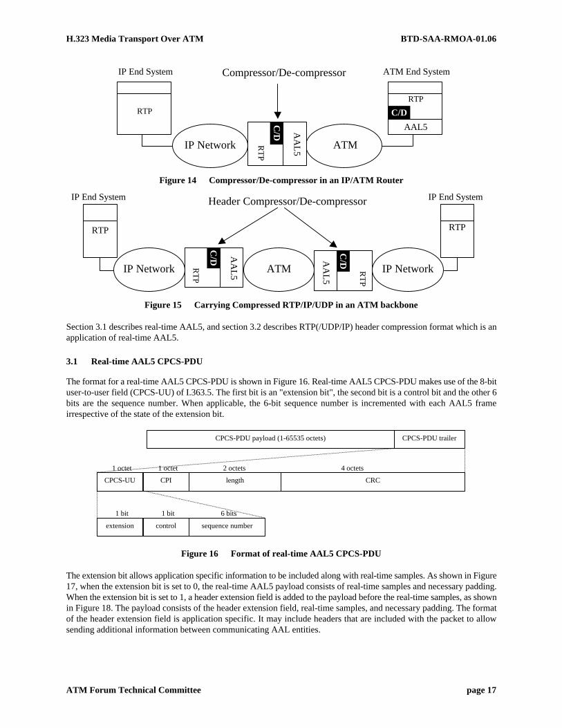
Table 6 IP over ATM voice packing efficiency using H.323 defaults
A.2 RTP over ATM media stream transport (H.323/Annex C)
Using RTP over ATM media stream transport eliminates the UDP, IP and multiprotocol encapsulation overhead and limitsthe minimum overhead to 12 octets. Table 7 illustrates the efficiency of using the H.323 defaults with an RTP over ATMmethod. In Table 7, the size of the overhead is always the minimum possible since it refers to the minimum RTP and IPheaders.
This fixed extra overhead is important enough that there is not much point in trying to optimize the packetization forpayload efficiency. It is thus recommended to use the H.323 defaults. If greater packetization efficiency is desired, thecompressed RTP/UDP/IP method is preferred.
Table 7 RTP over ATM voice packing efficiency using H.323 defaults
A.3 Compressed RTP over ATM media stream transport
Using compressed RTP/UDP/IP over ATM media stream transport means that in most cases, the RTP overhead iseliminated, making the method just as efficient as Native ATM media stream transport. Table 8 illustrates the efficiencyof using the H.323 defaults with an compressed RTP over ATM media stream transport method. In the following tables,the size of the overhead is the minimum since it refers to the fully compressed RTP headers.
Table 8 CompressedRTP over ATM voice packing efficiency using H.323 defaults
It is however possible to improve the efficiency by choosing payload sizes that are better suited to ATM AAL5 CPCS-PDU encapsulation, when possible, as shown in Table 9.
Table 9 Compressed RTP over ATM voice packing efficiency using optimized payload sizes
Table 9 shows that 100% efficiency is achieve, while maintaining the absolute minimum packetization delay, by using40 octets (i.e., one cell) as the default payload size for all H.323 voice encoding except G.723.1 because it is not possible.
• G.711 and G.722
To minimize latency and to interwork with af-vtoa-0083.000 and H.321 over AAL5, a default CPCS-PDU size of40 octets should be use. This also corresponds to the default AAL2 payload size for PCM.
• G.723.1
In order not to introduce any additional delay, a default CPCS-PDU size of 40 octets should be used. G.723.1 cannot be efficiently encoded with AAL5.
• G.728
Using a CPCS-PDU size of 40 octets matches perfectly the H.323 default packet sizes of 8 frames per packet.
• G.729
G.729 packetization is much more efficient if 4 frames are included per CPCS-PDU instead of the H.323 default of2 since it corresponds exactly to one cell. Note that since the side that requests the smallest size voice payload winsthe negotiation, if the other side chooses the H.323 default, the efficiency will be quite low.
However, using 4 frames instead of two will double the packetization delay to 40 ms, which may not always besuitable.
BTD-SAA-RMOA-01.06 H.323 Media Transport Over ATM
page 30 ATM Forum Technical Committee
Annex B Using ATM as an access link to carry compressed RTP/UDP/IP media stream transport
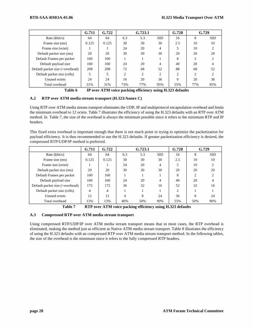
When the end systems are H.323 terminals and are connected into the network using ATM as an access link, there arecases where having the UDP and IP headers becomes desirable. This scenario is depicted in Figure 28. As shown insection 1.5.1, the typical (and minimum) RTP/UDP/IP overhead amounts to 40 octets, plus another 8 octets for themultiprotocol encapsulation.
C/D IPnetwork
H.323 H.323 ATMnetwork
C/D
Figure 28 Header compression using ATM as an access link
In this case, the header compression and decompression is performed at the interface to the ATM link, in the H.323terminal. In this case, there is no gateway between the terminal and the ATM network. The H.323 terminal may wish tocommunicate to a H.323 terminal that is connected to an IP network. In this case, the ATM enabled H.323 terminalpotentially sets up an ATM virtual circuit to an egress point in the ATM network. However, it is necessary to communicatethe UDP and IP headers across the IP network so that the packets may be routed through the IP network to the remoteH.323 terminal. In this scenario, it is thus desirable that the IP and UDP headers are not elided. Rather, the IP and UDPheaders would be compressed over the ATM network, and would be decompressed at the router on which the ATM SVCterminates. In this case, the setting up of the compressor and decompressor state would occur when the SVC is set upbetween the H.323 terminal and the remote egress router going out to the IP network. It would require the decompressorto look at the data stream after the SVC is setup to initialize the state of the decompressor, just as is done in [28].
The motivation for this method is to allow for H.323 terminals to be connected over access technolo-gies such as xDSL,where ATM may be the datalink layer protocol carried over the ADSL link. It would imply that we do not need to havea PPP protocol run over the ATM virtual circuit, and instead have a single datalink layer protocol over the xDSL link. Thecommunication of the IP header allows us to route the media stream in the IP network, beyond the ATM network, whileretaining the benefits of compressing the RTP/UDP/IP headers over the ATM virtual circuit.
This method uses ATM as a transparent access link and thus does not make use of the call and connection controlprocedures of section 2. The compression of RTP headers is described in section 3.
This method uses real time AAL5, as described in section 3.1 to transport media streams that have associated RTP, UDPand IP headers. The intent of this method is to exploit compression techniques for RTP, UDP and IP headers, and totransport the compressed headers and media stream efficiently on ATM.
H.323 Media Transport Over ATM BTD-SAA-RMOA-01.06
ATM Forum Technical Committee page 31
Media stream
RTP
UDP
IP
Compressor/
Decompressor
AAL5
ATM
Figure 29 Compressed RTP/UDP/IP over ATM media stream transport
The method described in this section is based on the method described in 3.2, except that the compression mechanismapplies to the RTP, UDP and IP layers as a whole, as per [28].
The call context used by this annex would be as per [28]. The packets formats used by this annex are the following:
• FULL_RTP_UDP_IP_HEADER - this packet format corresponds to FULL_HEADER in [28].
• CONTEXT_STATE – this packet format corresponds to CONTEXT_STATE in [28] and is the same as for RTP onlyheader compression.
• COMPRESSED_RTP_UDP_IP - this packet format corresponds to either COMPRESSED_RTP_8 orCOMPRESSED_RTP_16 in [28] since the VPI/VCI is used as the context identifier.
• COMPRESSED_UDP_IP - this packet format corresponds to either COMPRESSED_UDP_8 orCOMPRESSED_UDP_16 in [28] since the VPI/VCI is used as the context identifier.
• ATM_COMPRESSED_HEADER – this packet format is the same as for RTP only header compression.
RTP/UDP/IP header compression over AAL5 is as per Figure 23, except that the C bit is an I bit, as per [28].
B.1 FULL_RTP_UDP_IP_HEADER packet format
The definition of a FULL_RTP_UDP_IP_HEADER packet given here is for the RTP/UDP/IP compression over real-timeAAL5 and corresponds to the FULL_HEADER packet format in [28]. The extension bit is set to '1' indicating that a headerextension is present. The control bit is set to '1' indicating the presence of a Control Byte to describe the packet type. TheControl byte is set to '00000010' indicating a FULL_RTP__UDP_IP_HEADER packet format. The AAL5 CPCS-PDUcontains a full RTP/UDP/IP header and payload. The MSTI bits are not sent since they do not apply to aFULL_RTP_UDP_IP_HEADER packet.
BTD-SAA-RMOA-01.06 H.323 Media Transport Over ATM
page 32 ATM Forum Technical Committee
AAL5 frame
AAL5 CPCS-PDU length11 CPISequence # CRC
UUI
AAL5 Trailer
RTP Data
Control Byte
UDPHeader
RTP Header& Extension
00000010 IPHeader
Figure 30 FULL_RTP_HEADER packet
4.5.1.1 CONTEXT_STATE packet format
See 3.2.2.2, with the exception that reference to FULL_RTP_HEADER should be to FULL_RTP_UDP_IP.
B.2 COMPRESSED_RTP_UDP_IP packet format
This packet format corresponds to COMPRESSED_RTP_8 or COMPRESSED_RTP_16 in [28], except that the UDPchecksum is never included since it is set to zero, and the sequence number is carried in the CPCS-APDU UUI . Theextension bit is set to '1' indicating that a header extension is present. The control bit is set to '1' indicating the presenceof a Control Byte to describe the packet type. The Control byte is set to '00000011' indicating aCOMPRESSED_RTP_UDP_IP packet format.
AAL5 frame
AAL5 CPCS-PDU length1 1 CPISequence # CRC
UUI
AAL5 Trailer
RTP Payload
RTP DataCompressed RTP/UDP/IPheaders
Control Byte
00000011
RTP header& Extension
UDPheader
IPheader
H.323 Media Transport Over ATM BTD-SAA-RMOA-01.06
ATM Forum Technical Committee page 33
Figure 31 COMPRESSED_RTP_UDP_IP packet
B.3 COMPRESSED_UDP_IP packet format
This packet format corresponds to COMPRESSED_UDP_8 or COMPRESSED_UDP_16 in [28], except that the UDPchecksum is never included since it is set to zero, and the sequence number is carried in the CPCS-APDU UUI . Theextension bit is set to '1' indicating that a header extension is present. The control bit is set to '1' indicating the presenceof a Control Byte to describe the packet type. The Control byte is set to '00000100' indicating a COMPRESSED_UDP_IPpacket format.
AAL5 frame
AAL5 CPCS-PDU length1 1 CPISequence # CRC
UUI
AAL5 Trailer
RTP Payload
RTP DataCompressed UDP/IPheaders
Control Byte
00000100
RTP header& Extension
UDPheader
IPheader
Figure 32 COMPRESSED_UDP_IP packet
B.4 ATM_COMPRESSED_HEADER packet format
See 3.2.2.4, with the exception that reference to FULL_RTP_HEADER should be to FULL_RTP_UDP_IP, and referenceto DELTA_RTP packet format should be to COMPRESSED_RTP_UDP_IP. Likewise, references to the C bit should bereplaced by references to the I bit.