25
Dept., of E.C.E, RCEW(3T),KNL. B.TECH CONTROL SYSTEMS ENGINEERING
Dept., of E.C.E, RCEW(3T),KNL.
B.TECH CONTROL SYSTEMS ENGINEERING


Code: 15A02303
B.Tech II Year II Semester (R15) Regular & Supplementary Examinations May/June 2018 CONTROL SYSTEMS ENGINEERING
(Common to ECE and EIE)
Time: 3 hours Max. Marks: 70
PART – A (Compulsory Question)
***** 1 Answer the following: (10 X 02 = 20 Marks) (a) Distinguish between open loop and closed loop systems. (b) State Mason’s gain formula. (c) List the time domain specifications. (d) Determine the static error constants for a system given by: G(s)H(s) = 10(𝑠𝑠+2)(𝑠𝑠+3)
𝑠𝑠(𝑠𝑠+1)(𝑠𝑠+4)(𝑠𝑠+5).
(e) State limitations for Routh’s stability. (f) How do you determine the centroid and angle of asymptotes? (g) Find the resonant frequency and resonant peak for a unity feedback system with: 𝐺𝐺(𝑠𝑠) = 100
𝑠𝑠(𝑠𝑠+10).
(h) What is Polar plot? (i) What are the advantages of state space analysis? (j) State the properties of state transition matrix.
PART – B (Answer all five units, 5 X 10 = 50 Marks)
UNIT – I
2 (a) Write differential equations for the mechanical system shown in figure below.
(b) Explain with a neat sketch, the working of Synchro transmitter and Receiver. OR
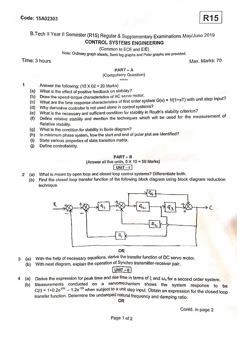
3 Determine the overall transfer function C/R for the block diagram shown in figure below by using block diagram reduction rules.
Contd. in page 2
Page 1 of 2
R15

Code: 15A02303
UNIT – II
4 Derive the expression for transient response of a under damped second order system with unit step input and draw the response curve.
OR 5 The block diagram of a unity feedback system is shown in figure below.
Determine the characteristic equation of the system: (i) Natural frequency. (ii) Damping factor. (iii) Damping frequency. (iv) Rise time. (v) Peak time. (vi) Peak overshoot.
UNIT – III
6 Determine the value of ‘a’ and ‘K’ at which a unity feedback control system having an open loop transfer function 𝐺𝐺(𝑠𝑠) = 𝐾𝐾(𝑠𝑠+1)
𝑆𝑆3+𝑎𝑎𝑆𝑆2+2𝑆𝑆+1 , will have sustained oscillations at ω = 2 rad/sec.
OR 7 Sketch the root locus plot for a system described by: G(s)H(s) = 𝐾𝐾
𝑠𝑠(𝑠𝑠+3)(𝑠𝑠+6). Comment on its stability.
Determine the value of K for (i) critical damping (ii) Marginal stability (iii) for damping factor 0.6.
UNIT – IV
8 The open loop transfer function of a system is given by: G(s) = 20𝑠𝑠(𝑠𝑠+1)(1+0.01𝑠𝑠). Sketch the Bode plot and
determine the gain Margin and Phase Margin. OR
9 The open loop transfer function of a system is given by: G(s) = 40(𝑠𝑠+4)(𝑠𝑠2+2𝑠𝑠+1). Sketch the Nyquist plot and
comment on the stability of the system.
UNIT – V
10 Determine the state vector x(t) for the state model ��̇�𝑥1�̇�𝑥2� = �−12 2/3
−36 −1 � �𝑥𝑥1𝑥𝑥2� + �1/3
1 � 𝑢𝑢 ; and the initial
conditions are x1(0) = 2, x2(0) =1. OR
11 State whether the system is controllable and observable for the linear time invariant system
characterized by the state model: ��̇�𝑥1�̇�𝑥2� = �0 1
2 −3� �𝑥𝑥1𝑥𝑥2� + �01� 𝑢𝑢,𝑌𝑌(𝑡𝑡) = [1 1] �
𝑥𝑥1𝑥𝑥2�.
*****
Page 2 of 2
R15

Code: 15A02303
B.Tech II Year II Semester (R15) Regular Examinations May/June 2017 CONTROL SYSTEMS ENGINEERING
(Common to ECE and EIE)
Time: 3 hours Max. Marks: 70
PART – A (Compulsory Question)
Use of polar chart, Bode graph sheet and Nyquist chart is allowed in examination hall.
***** 1 Answer the following: (10 X 02 = 20 Marks) (a) List the advantages of negative feedback in control system. (b) Write the Mason’s gain formula of signal flow graph. (c) How do you find the type of a control system? (d) Find the value of position error constant for second order system using ramp input. (e) Write the necessary and sufficient condition for stability in Routh’s stability criterion. (f) Define BIBO stability. (g) Write the expression for resonant peak in frequency response analysis. (h) What is meant by lag compensation? (i) Define state and state variable. (j) What are the properties of state transition matrix?
PART – B
(Answer all five units, 5 X 10 = 50 Marks)
UNIT – I
2 Derive the transfer function of DC servomotor. OR
3 Find the transfer function C(S) / R(S) for the system using block diagram reduction technique.
UNIT – II
4 (a) Transfer function of unity feedback control system is . Obtain the rise time, peak time,
maximum overshoot and the settling time when the system is subjected to a unity step input. (b) Derive the time response of first order system for step input. OR
5 The open loop transfer function of a system with unity feedback . Evaluate the static error constants of the system. Obtain the steady state error of the system, when subjected to an input given by the polynomial
Contd. in page 2
Page 1 of 2
R15
Code: 15A02303
UNIT – III
6 Draw the root locus plot for the system whose open loop transfer function is given by:
OR 7 Obtain the Routh array for the system whose characteristic polynomial equation is:
Check the stability.
UNIT – IV
8 Explain in detail about lag-lead compensator technique. OR
9 The open loop transfer function of a unity feedback system is given by: Sketch polar plot and determine the gain and phase margin.
UNIT – V
10 Consider a system with state model given below:
Verify, the system is observable and controllable. OR
11 (a) Obtain the state model of the system described by the following transfer function:
(b) Explain about diagonalization.
*****
Page 2 of 2
R15
Code: 15A02303
B.Tech II Year II Semester (R15) Supplementary Examinations December 2017 CONTROL SYSTEMS ENGINEERING
(Common to ECE and EIE)
Time: 3 hours Max. Marks: 70
PART – A (Compulsory Question)
***** 1 Answer the following: (10 X 02 = 20 Marks) (a) Compare open loop control system and closed loop control system. (b) What is servomechanism? (c) What is steady state error? (d) Mention two advantages of generalized error constants over static error constants. (e) How the roots of characteristic equation are related to stability? (f) What is centroid? How the centroid is calculated? (g) For a second order system, the damping ratio is 0.5 and natural frequency of oscillation is 8 rad/sec.
Calculate resonant peak and resonant frequency. (h) What are the advantages of Bode plot? (i) What is companion or bush form of state model? (j) What are phase variables?
PART – B (Answer all five units, 5 X 10 = 50 Marks)
UNIT – I
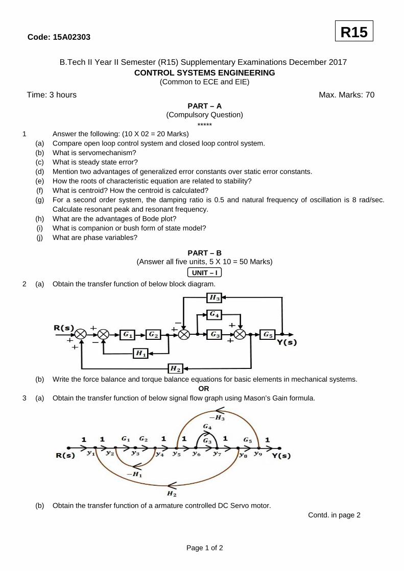
2 (a) Obtain the transfer function of below block diagram.
(b) Write the force balance and torque balance equations for basic elements in mechanical systems. OR
3 (a) Obtain the transfer function of below signal flow graph using Mason’s Gain formula.
(b) Obtain the transfer function of a armature controlled DC Servo motor.
Contd. in page 2
Page 1 of 2
R15

Code: 15A02303
UNIT – II
4 (a) Derive an expression for the underdamped response of a second order feedback control system for step input.
(b) For a unity feedback control system, the open loop transfer function is: is . Find position,
velocity and acceleration error constants. OR
5 (a) For a unity feedback control system, the open loop transfer function is: . Find steady state
error when the input . (b) Obtain expressions for rise time and peak time for a second order feedback control system for step
input.(under damped case)
UNIT – III
6 (a) The open loop transfer function of a unity feedback control system is given by: G(s) =
by applying Routh criterion, discuss the stability of the closed loop system as a function of K. Determine the values of K which will cause sustained oscillations in the closed loop system. What are the corresponding oscillation frequencies?
(b) Define the following terms with respect to Root locus technique: (i) Centroid. (ii) Asymptote. (iii) Break away point.
OR 7 (a) The open loop transfer function of a unity feedback control system is given by: G(s) = . Sketch
the root locus of the system. (b) Using Routh criterion, determine the stability of the system represented by the characteristic equation
. Comment on the location of the roots of characteristic equation.
UNIT – IV
8 (a) The open loop transfer function of a system is . Sketch the Nyquist plot and
determine the stability of closed loop system. If the closed loop system is not stable then find the number of closed loop poles lying on the right half of s plane.
(b) Sketch the polar plot of: (i) . (ii) . (iii)
OR 9 The open loop transfer function of a unity feedback control system is given by . Draw
the Bode plot and find K so that the system is stable with, (i) Gain margin is equal to 2db. (ii) Phase margin is equal to 450.
UNIT – V
10 (a) Determine the canonical state model of the system whose transfer function is: and
draw block diagram representation of the state model. (b) Write the properties of state transition matrix. OR
11 (a) Determine the state model of the system whose transfer function is: and draw block diagram representation of the state model.
(b) Define controllability and observability and state the condition for controllability and observability.
*****
Page 2 of 2
R15

Code: 15A02303
B.Tech II Year I Semester (R15) Regular & Supplementary Examinations November/December 2018 CONTROL SYSTEMS ENGINEERING
Time: 3 hours Max. Marks: 70
PART – A (Compulsory Question)
***** 1 Answer the following: (10 X 02 = 20 Marks) (a) What is the effect of positive feedback on stability of the system? (b) What is the basic rule used for block diagram reduction technique? (c) What are test signals and write their significance? (d) Define IAE, ITAE. (e) Determine the stability of the system whose characteristic equation is given by:
𝑆4 + 6𝑆3 + 23𝑆2 + 40𝑆 + 50 = 0 using Routh’s stability criterion. (f) Draw the Root-Locus plot of 𝐺(𝑆) 𝐻(𝑆) = 𝐾
𝑆+𝑃.
(g) Define gain margin and phase margin. (h) Define state and state variable. (i) What are the advantages of state space modeling using physical variables? (j) What is similarity transformation?
PART – B
(Answer all five units, 5 X 10 = 50 Marks)
UNIT – I
2 (a) Explain the operation of synchro transmitter and receiver. (b) Write the block diagram reduction techniques in the analysis of control systems. OR
3 (a) Write the analogy between mechanical systems and electrical systems. (b) Determine C/R of the system shown in figure below by block diagram reduction technique.
UNIT – II
4 (a) For a unity feed-back system whose open-loop transfer function is 𝐺(𝑆) = 100(1+0.2𝑆)(1+2𝑆)
. Find the
position, velocity and acceleration error constants. (b) What will be the nature of response of a second order system with different types of damping? OR
5 (a) Derive the expression for 2nd order system under damped system with unit step as input. (b) The open loop, transfer function of a unity feedback system is 𝐺(𝑆) = 1
1+𝑆. Using generalized error
series determine the steady state error when the system is excited by 𝑅(𝑡) = 1 + 𝑡 + 𝑡2.
Contd. in page 2
Page 1 of 2
R15
𝐶 R
+
−
+
−
+ 𝐺2 𝐺1
H1
(Electrical & Electronics Engineering)
Code: 15A02303
UNIT – III
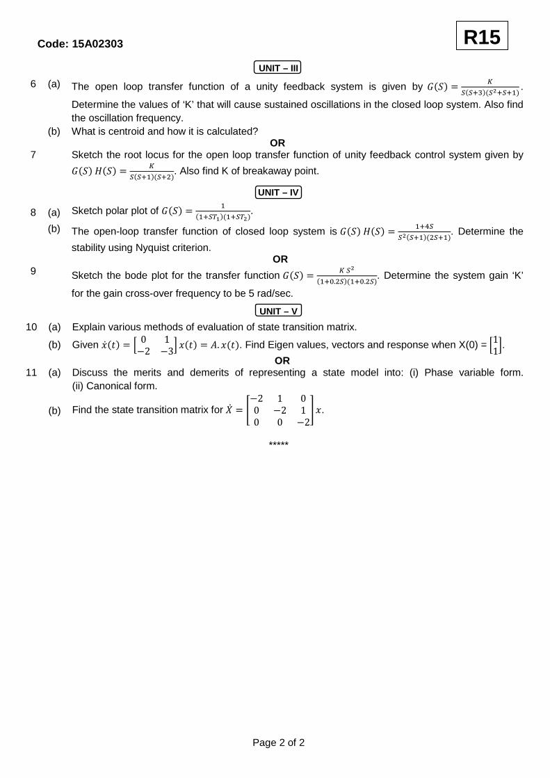
6 (a) The open loop transfer function of a unity feedback system is given by 𝐺(𝑆) = 𝐾𝑆(𝑆+3)(𝑆2+𝑆+1)
.
Determine the values of ‘K’ that will cause sustained oscillations in the closed loop system. Also find the oscillation frequency.
(b) What is centroid and how it is calculated? OR
7 Sketch the root locus for the open loop transfer function of unity feedback control system given by 𝐺(𝑆) 𝐻(𝑆) = 𝐾
𝑆(𝑆+1)(𝑆+2). Also find K of breakaway point.
UNIT – IV
8 (a) Sketch polar plot of 𝐺(𝑆) = 1(1+𝑆𝑇1)(1+𝑆𝑇2)
.
(b) The open-loop transfer function of closed loop system is 𝐺(𝑆) 𝐻(𝑆) = 1+4𝑆𝑆2(𝑆+1)(2𝑆+1)
. Determine the stability using Nyquist criterion.
OR 9 Sketch the bode plot for the transfer function 𝐺(𝑆) = 𝐾 𝑆2
(1+0.2𝑆)(1+0.2𝑆). Determine the system gain ‘K’
for the gain cross-over frequency to be 5 rad/sec.
UNIT – V
10 (a) Explain various methods of evaluation of state transition matrix. (b) Given �̇�(𝑡) = � 0 1
−2 −3� 𝑥(𝑡) = 𝐴. 𝑥(𝑡). Find Eigen values, vectors and response when X(0) = �11�. OR
11 (a) Discuss the merits and demerits of representing a state model into: (i) Phase variable form. (ii) Canonical form.
(b) Find the state transition matrix for �̇� = �
−2 1 00 −2 10 0 −2
� 𝑥.
*****
Page 2 of 2
R15

Code: 13A02402
B.Tech III Year I Semester (R13) Supplementary Examinations June 2017 CONTROL SYSTEMS ENGINEERING
(Common to ECE and EIE)
Time: 3 hours Max. Marks: 70
PART – A (Compulsory Question)
***** 1 Answer the following: (10 X 02 = 20 Marks) (a) If a forward path touched all closed loops, what would be the value of ? (b) Write the analogous electrical elements in force voltage analogy for the elements of mechanical
translational system. (c) Define impulse signal with its waveform. (d) How the system was classified depending on the value of the damping? (e) Why marginally stable systems are considered unstable under the BIBO definition of stability? (f) What kind of compensation improves the steady-state error? (g) Write a short note on the correlation between the time and frequency response. (h) How closed loop frequency response is determined from open loop frequency response using M and N
circles? (i) How can the poles of a system be found from the state equations? (j) Write the general form of the state-transition matrix. How many constants would have to be found?
PART – B
(Answer all five units, 5 X 10 = 50 Marks)
UNIT – I
2 Using Mason’s rule, find the transfer function, , for the system represented by figure below.
OR 3 A motor and generator are set up to drive a load as shown in figure below. If the generator output voltage
is , where is the generator’s field current, find the transfer function . For the
generator, . For the motor, , and
Contd. in page 2
Page 1 of 2
R13
G1 (s) G2 (s)
G3 (s)
G4 (s)
G5 (s)
G6 (s) G7 (s)
H1 (s) H2 (s)
H3 (s)
R (s) C (s) 1
Code: 13A02402
UNIT – II
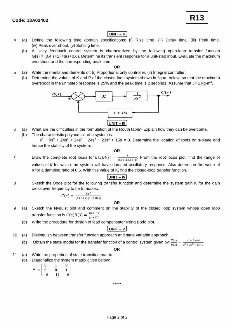
4 For the system of figure below, find the values of K1 and K2 to yield a peak time of 1.5 second and a settling time of 3.2 seconds for the closed-loop system’s step response.
OR
5 (a) What pole locations characterize: (i) The under damped system. (ii) The over damped system. (iii) The critically damped system.
(b) A system has a damping ratio of 0.5, a natural frequency of 100 rad/s and a DC gain of 1. Find the response of the system to a unit step input.
UNIT – III
6 Consider the unity feedback system shown with transfer function . Draw the root locus
and identify the stability. OR
7 Using the Routh-Hurwitz criterion and the unity feedback system with .
(i) Find the range of K for stability. (ii) Find the value of K for marginal stability. (iii) Find the actual location of the closed-loop poles when the system is marginally stable.
UNIT – IV
8 Make a polar plot of the frequency response for the transfer function given by:
OR 9 Given a unity feedback system with the forward-path transfer function and a delay
of 0.5 second, find the range of gain, K, to yield stability. Use Bode plots.
UNIT – V
10 Give the following state-space representation of a system, find Y(s):
OR 11 Solve for y(t) for the following system represented in state space, where u(t) is the unit step. Use the
Laplace transform approach to solve the state equation.
*****
Page 2 of 2
R13
Code: 13A02402
B.Tech III Year I Semester (R13) Regular & Supplementary Examinations November/December 2016
CONTROL SYSTEMS ENGINEERING (Common to ECE and EIE)
Time: 3 hours Max. Marks: 70
PART – A (Compulsory Question)
***** 1 Answer the following: (10 X 02 = 20 Marks) (a) Why is negative feedback preferred as compared to positive feedback in a closed loop system? (b) Write any three basic properties of signal flow graph. (c) Mention any two advantages of generalized error coefficients. (d) A unity feedback system has a open loop transfer function of . Determine steady state
error for unit step input. (e) State the rule for finding the value of gain K at any point s0 on the root locus diagram. (f) In Routh array what conclusion you can make when there is a row of all zeros? (g) Mention any two advantages and any two disadvantages of frequency response analysis. (h) Which characteristic feature of the lag network is utilized for compensation? (i) Give the expression to obtain the transfer function of a system from the given state model:
(j) Is the state-model of a system unique?
PART – B (Answer all five units, 5 X 10 = 50 Marks)
UNIT – I
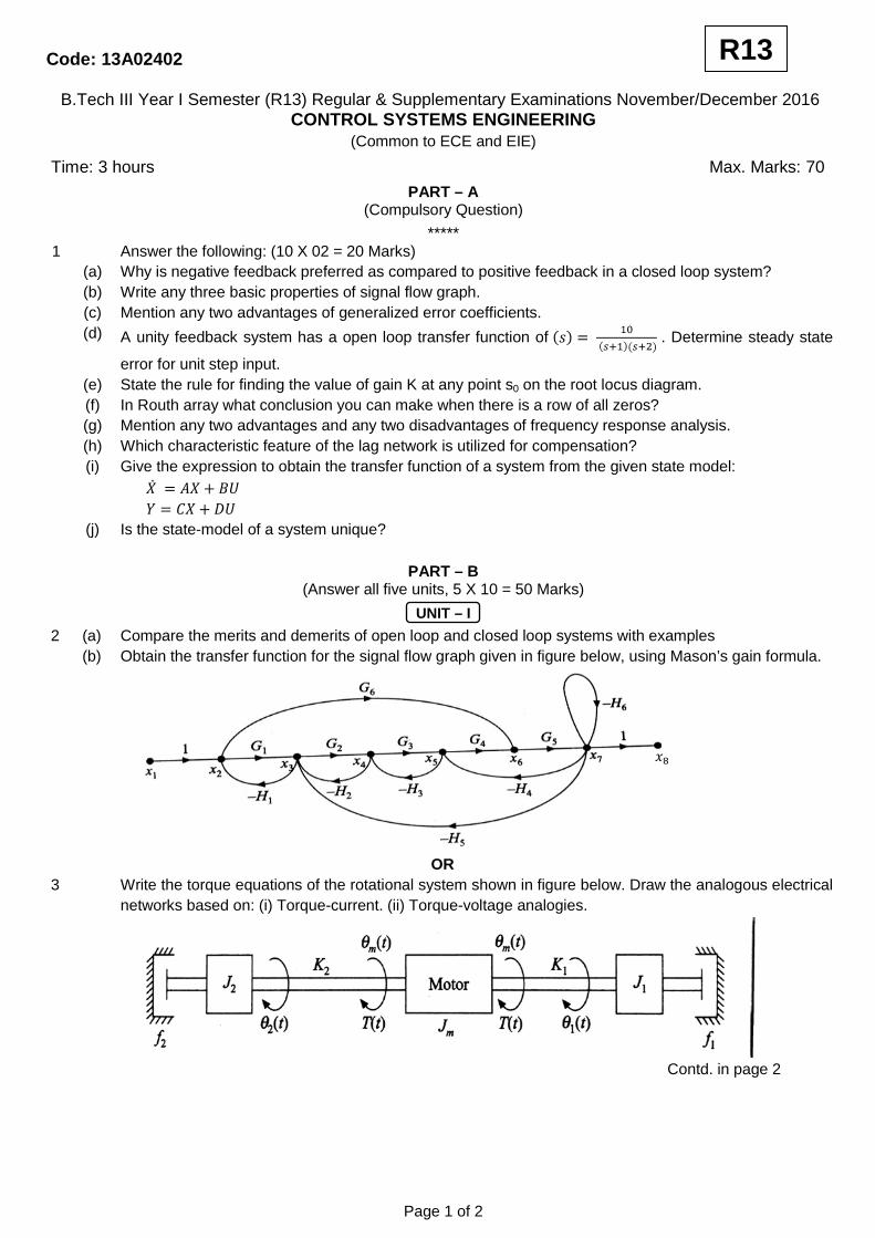
2 (a) Compare the merits and demerits of open loop and closed loop systems with examples (b) Obtain the transfer function for the signal flow graph given in figure below, using Mason’s gain formula.
OR
3 Write the torque equations of the rotational system shown in figure below. Draw the analogous electrical networks based on: (i) Torque-current. (ii) Torque-voltage analogies.
Contd. in page 2
Page 1 of 2
R13
Code: 13A02402
UNIT – II
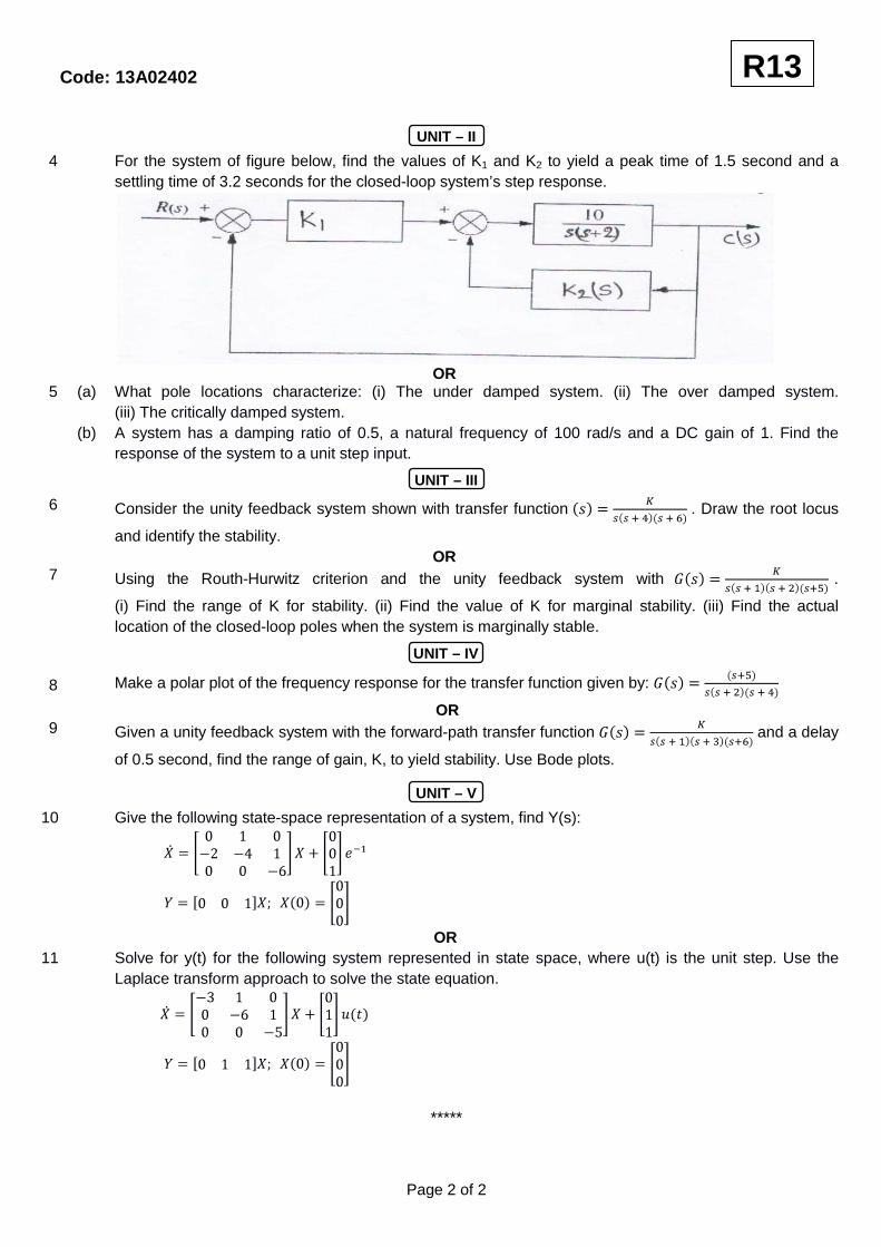
4 (a) Define the following time domain specifications: (i) Rise time. (ii) Delay time. (iii) Peak time. (iv) Peak over shoot. (v) Settling time.
(b) A Unity feedback control system is characterized by the following open-loop transfer function G(s) = (0.4 s+1) / s(s+0.6). Determine its transient response for a unit-step input. Evaluate the maximum overshoot and the corresponding peak time.
OR 5 (a) Write the merits and demerits of: (i) Proportional only controller. (ii) Integral controller. (b) Determine the values of K and P of the closed-loop system shown in figure below, so that the maximum
overshoot in the unit-step response is 25% and the peak time is 2 seconds. Assume that J= 1 kg-m2.
UNIT – III
6 (a) What are the difficulties in the formulation of the Routh table? Explain how they can be overcome. (b) The characteristic polynomial of a system is:
s7 + 9s6 + 24s5 + 24s4 + 24s3 + 23s2 + 15s = 0. Determine the location of roots on s-plane and hence the stability of the system.
OR 7 Draw the complete root locus for . From the root locus plot, find the range of
values of for which the system will have damped oscillatory response. Also determine the value of K for a damping ratio of 0.5. With this value of K, find the closed-loop transfer function.
UNIT – IV
8 Sketch the Bode plot for the following transfer function and determine the system gain K for the gain cross over frequency to be 5 rad/sec.
OR 9 (a) Sketch the Nyquist plot and comment on the stability of the closed loop system whose open loop
transfer function is .
(b) Write the procedure for design of lead compensator using Bode plot.
UNIT – V
10 (a) Distinguish between transfer function approach and state variable approach. (b) Obtain the state model for the transfer function of a control system given by: .
OR 11 (a) Write the properties of state transition matrix. (b) Diagonalize the system matrix given below:
A =
*****
Page 2 of 2
R13
Code: 13A02402
B.Tech III Year I Semester (R13) Supplementary Examinations June 2016
CONTROL SYSTEMS ENGINEERING (Common to ECE and EIE)
(Use of ordinary graph sheets, semi log graphs and polar graphs is permitted in the examination hall)
Time: 3 hours Max. Marks: 70
PART – A (Compulsory Question)
***** 1 Answer the following: (10 X 02 = 20 Marks) (a) Prove that the closed loop transfer function of a unity negative feedback control system having the
forward path transfer function is given by .
(b) In an electrical circuit where is current, is Capacitance and is Voltage. Write the analogous equations for: (i) Mechanical (translational) system. (ii) Mechanical (rotational) system. Use force-current analogy.
(c) Define ‘TYPE’ and ‘ORDER’ of a system. What are the TYPE and ORDER of ?
(d) What is the effect of adding integral action to a proportional controller on: (i) Steady state error? (ii) Relative stability?
(e) What is the location of breakaway point in the root locus for the open loop transfer function: .
(f) When is a system said to be Bounded Input-Bounded Output (BIBO) stable? What is the condition on impulse response for BIBO stability?
(g) A unity feedback system has What is the resonant frequency of the system?
(h) What is the importance of cut-off frequency and cut-off rate in control systems? (i) Define ‘State’ and ‘State variables’. (j) What is the characteristic equation of a system having the State Matrix?
A =
PART – B (Answer all five units, 5 X 10 = 50 Marks)
UNIT – I
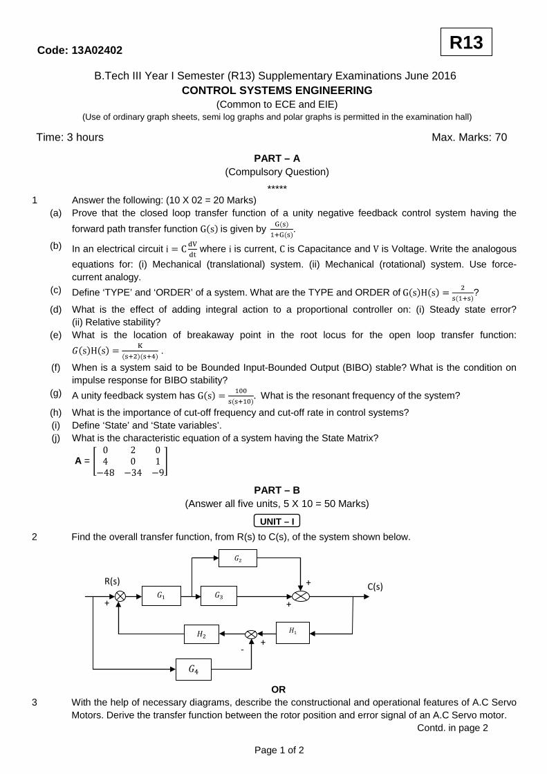
2 Find the overall transfer function, from R(s) to C(s), of the system shown below.
OR 3 With the help of necessary diagrams, describe the constructional and operational features of A.C Servo
Motors. Derive the transfer function between the rotor position and error signal of an A.C Servo motor. Contd. in page 2
Page 1 of 2
R13
C(s) R(s) +
+ +
+ -
Code: 13A02402
UNIT – II
4 (a) A system has the closed loop transfer function . It is required that the unit step response of
the system should have a settling time of 2 sec according to 2% criterion; and the overshoot should be approximately 5%. What should be the closed loop pole locations?
(b) A unity feedback control system has the closed loop transfer function . Determine the steady state error in the unit ramp response, in terms of and
OR 5 Derive the expressions for: (i) Rise time. (ii) Peak time. (iii) Maximum overshoot. (iv) Settling time of the
unit-step response of an under damped prototype second order system. Hence determine the quantities for a system having the closed loop transfer function
UNIT – III
6 (a) How many roots of the characteristic polynomial of a system have positive real parts? (b) Determine the value of for which the characteristic polynomial of a system
has roots with zero real part. OR
7 A unity feedback system has the open loop transfer function .
(a) Sketch the root locus for (b) At what value of does the system become unstable? (c) What is frequency of sustained oscillations of the system when it just loses stability?
UNIT – IV
8 (a) Draw the Bode plot and determine the Gain Margin and Phase Margin for .
(b) A Unity feedback control system has the Open Loop Transfer Function . What should be the value of for the system to have Phase Margin of
OR 9 (a) Draw a network of lag-lead compensator consisting of resistors and capacitors and derive its transfer
function. (b) Draw the Nyquist plot for the open loop transfer function . Applying Nyquist stability
criterion, determine whether the closed loop system is stable or not.
UNIT – V
10 Obtain the state model for the system represented by:
OR
11 The state space representation of a system has the characteristic matrix and output
matrix . Find the zero excitation response of the system for .
*****
Page 2 of 2
R13
Code: 13A02402
B.Tech III Year I Semester (R13) Regular Examinations December 2015
CONTROL SYSTEMS ENGINEERING (Common to ECE and EIE)
(Use of ordinary graph sheets, semi log graphs and polar graphs are permitted in the examination hall)
Time: 3 hours Max. Marks: 70
PART – A (Compulsory Question)
***** 1 Answer the following: (10 X 02 = 20 Marks) (a) What is the effect of positive feedback on stability? (b) What are the differences between Synchro transmitter and control transformer? (c) The closed loop transfer function of a second order system is . What is the type of
damping in the system? (d) Why derivative controller is not used alone in control systems? (e) What is the necessary and sufficient condition for stability in Routh’s stability criterion? (f) What is meant by damping pole in Root locus diagram? (g) Define Gain margin and Phase margin. (h) In minimum phase system, how the start and end of polar plot are identified? (i) State various properties of state transition matrix. (j) What are the advantages of state space analysis over transfer function analysis?
PART – B (Answer all five units, 5 X 10 = 50 Marks)
UNIT – I
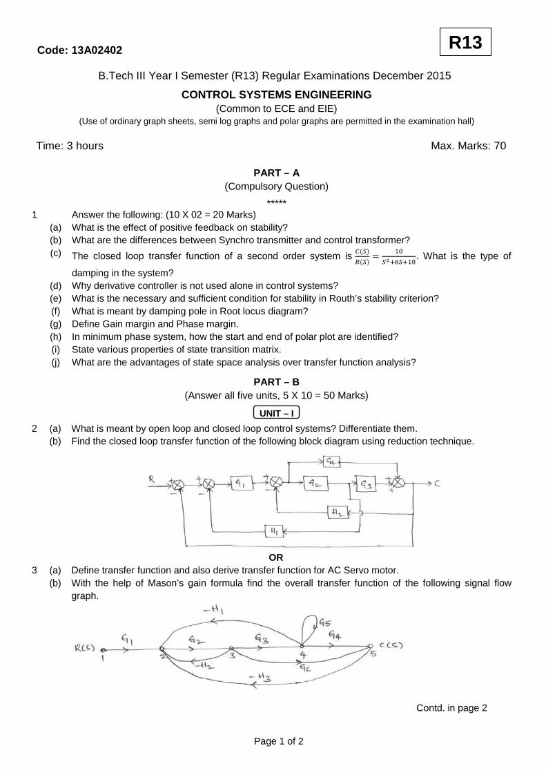
2 (a) What is meant by open loop and closed loop control systems? Differentiate them. (b) Find the closed loop transfer function of the following block diagram using reduction technique.
OR
3 (a) Define transfer function and also derive transfer function for AC Servo motor. (b) With the help of Mason’s gain formula find the overall transfer function of the following signal flow
graph.
Contd. in page 2
Page 1 of 2
R13
Code: 13A02402
UNIT – II
4 (a) Obtain the response of a first order system for unit step input.
(b) A closed loop servo is represented by the differential equation: . Where ‘c’ is the displacement of the output shaft, ‘r’ is the displacement of the input shaft and e = r – c. Determine un damped natural frequency, damping ratio and percentage maximum overshoot for unit step input.
OR 5 (a) What is meant by transient response and steady state response? Explain in detail about various time
domain specifications. (b) Find the various static error constants for a unity feedback control system whose open loop transfer
function is: .
UNIT – III
6 With the help of Routh’s stability criterion find the stability of the following systems represented by the characteristic equations: (i) s4 + 8s3 + 18s2 + 16s + 5 = 0. (ii) s6 + 2s5 + 8s4 + 12s3 + 20s2 + 16s + 16 = 0. (iii) s5 + s4 + 2s3 + 2s2 + 3s + 5 = 0.
OR 7 A negative feedback control system has the forward path transfer function: .
Draw the root locus for 0 ≤ K ≤ ∞.
UNIT – IV
8 Sketch the bode plot for the following transfer function and determine phase margin and gain margin: .
OR 9 The open loop transfer function of a unity feedback system is given by: . Sketch the
polar plot and determine the gain margin and phase margin.
UNIT – V
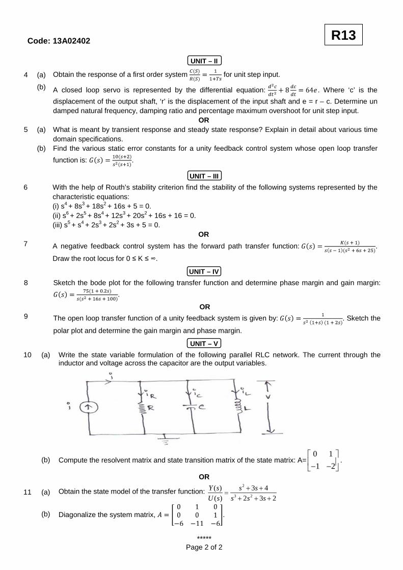
10 (a) Write the state variable formulation of the following parallel RLC network. The current through the inductor and voltage across the capacitor are the output variables.
(b) Compute the resolvent matrix and state transition matrix of the state matrix: A=0 11 2
− −
.
OR
11 (a) Obtain the state model of the transfer function: 2
3 2
( ) 3 4( ) 2 3 2
Y s s sU s s s s
+ +=
+ + +
(b) Diagonalize the system matrix, .
*****
Page 2 of 2
R13
Code: 13A02402
B.Tech III Year II Semester (R13) Regular & Supplementary Examinations May/June 2017 CONTROL SYSTEM ENGINEERING
Time: 3 hours Max. Marks: 70
PART – A (Compulsory Question)
***** 1 Answer the following: (10 X 02 = 20 Marks) (a) Name three basic forms for interconnecting subsystems. (b) What is sink and source? (c) What is proportional controller and what are its advantages? (d) State the importance of test signals. (e) What would happen to a physical system that becomes unstable? (f) When the maximum phase lead occurs in lead compensator? (g) What are the frequency domain specifications? (h) What are advantages of frequency response analysis? (i) Write short notes on BIBO stability. (j) Briefly describe the design procedure for a controller.
PART – B
(Answer all five units, 5 X 10 = 50 Marks)
UNIT – I
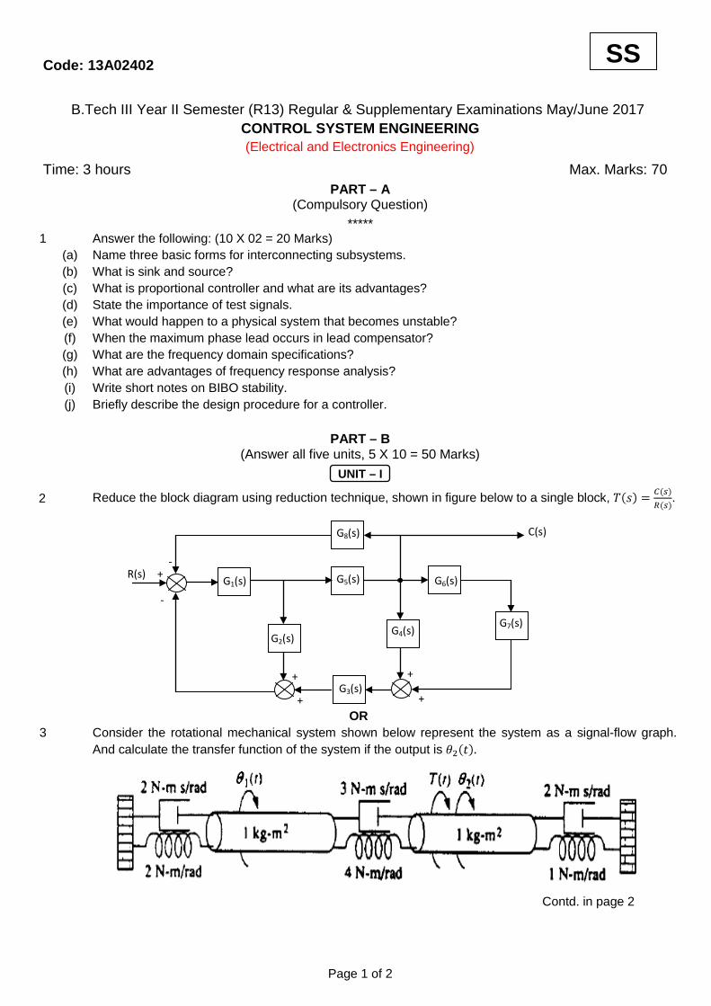
2 Reduce the block diagram using reduction technique, shown in figure below to a single block, .
OR 3 Consider the rotational mechanical system shown below represent the system as a signal-flow graph.
And calculate the transfer function of the system if the output is
Contd. in page 2
Page 1 of 2
SS
G1(s)
G8(s)
G6(s) G5(s)
G4(s) G2(s)
G7(s)
G3(s) +
+ +
+
+
-
-
C(s)
R(s)
(Electrical and Electronics Engineering)

Code: 13A02402
UNIT – II
4 For the system shown in figure below, find the following: (i) The damping ratio. (ii) Natural frequency. (iii) % overshoot. (iv) Settling time. (v) Peak time. (vi) Rise time. (vii) Damped frequency of oscillation.
OR
5 (a) Sketch the time response of the second order system and explain each component briefly. (b) For the system shown in figure below, find K and to yield a settling time of 0.15 second and a 30%
overshoot.
UNIT – III
6 Determine the stability of the closed-loop transfer function using R-H criteria.
OR 7 Consider the unity feedback system shown with transfer function: . Draw the root
locus and identify the stability.
UNIT – IV
8 For the given transfer function: , sketch the Bode asymptotic magnitude and asymptotic
phase plots. OR
9 Consider the unity feedback system shown with the transfer function: . Find the:
(i) Gain margin. (ii) Phase margin. (iii) Zero dB frequency. Using Nyquist diagram.
UNIT – V
10 (a) What are the properties of state transition matrix? (b) Given the system represented in state space by:
Solve for t he state transition matrix. OR
11 A system is represented by the state and output equations that follow. Find: (i) The characteristic equation. (ii) The poles of the system.
*****
Page 2 of 2
SS
Code: 13A02402
B.Tech II Year II Semester (R13) Supplementary Examinations December/January 2015/2016 CONTROL SYSTEMS ENGINEERING
Time: 3 hours Max. Marks: 70
PART – A (Compulsory Question)
***** 1 Answer the following: (10 X 02 = 20 Marks) (a) List all electrical analogs of rotational mechanical systems using force-current analogy. (b) A closed loop control system has an open loop gain of 100. Its feedback loop has a gain of 0.005. Find
its sensitivity for negative feedback. (c) Write the expressions for the response of first order system to the unit step input signal and unit ramp
input signal in time domain. (d) What is a type 1 system? What is its steady state error for unit ramp input? (e) Determine the stability of the system with the characteristic equation (f) Discuss the effect of addition of open loop poles on the root loci. (g) Define gain margin. (h) Define gain cross-over point. (i) Define the state of a system. (j) Derive the response of unforced system.
PART – B
(Answer all five units, 5 X 10 = 50 Marks)
UNIT – I
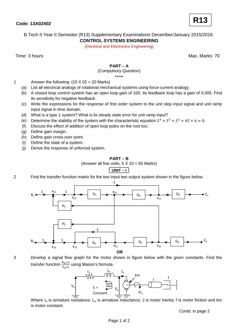
2 Find the transfer function matrix for the two input two output system shown in the figure below.
OR 3 Develop a signal flow graph for the motor shown in figure below with the given constants. Find the
transfer function using Mason’s formula.
Where ra is armature resistance; La is armature inductance; J is motor inertia; f is motor friction and km is motor constant.
Contd. in page 2
Page 1 of 2
R13
G1 G2 G3
G4 G5 G6
H1
H2
-1
-1
C1
C2
x11
x12 x13
x14
x21 x22 x23 x24
1 1
1 1
ra La
Eb m
Va
Ιa
Ιf = Constant
km J f
R1
R2
(Electrical and Electronics Engineering)
Code: 13A02402
UNIT – II
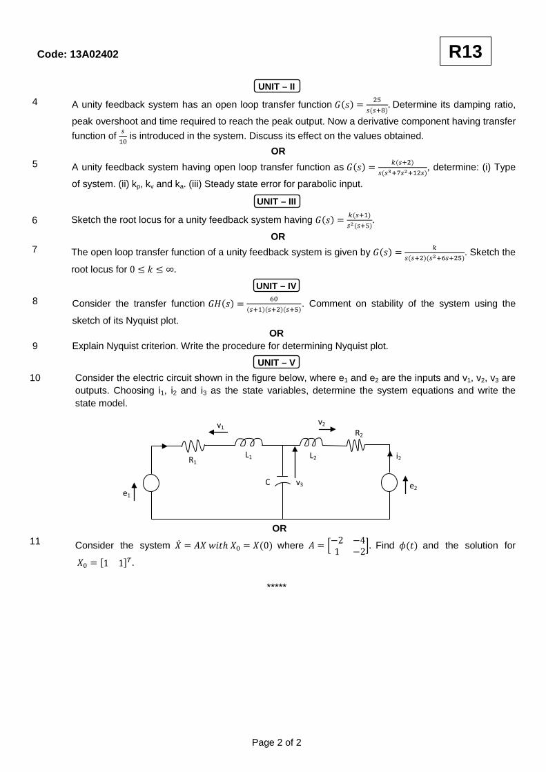
4 A unity feedback system has an open loop transfer function Determine its damping ratio,
peak overshoot and time required to reach the peak output. Now a derivative component having transfer function of is introduced in the system. Discuss its effect on the values obtained.
OR 5 A unity feedback system having open loop transfer function as , determine: (i) Type
of system. (ii) kp, kv and ka. (iii) Steady state error for parabolic input.
UNIT – III
6 Sketch the root locus for a unity feedback system having
OR 7 The open loop transfer function of a unity feedback system is given by . Sketch the
root locus for
UNIT – IV
8 Consider the transfer function . Comment on stability of the system using the
sketch of its Nyquist plot. OR 9 Explain Nyquist criterion. Write the procedure for determining Nyquist plot.
UNIT – V
10 Consider the electric circuit shown in the figure below, where e1 and e2 are the inputs and v1, v2, v3 are outputs. Choosing i1, i2 and i3 as the state variables, determine the system equations and write the state model.
OR 11 Consider the system where Find and the solution for
*****
Page 2 of 2
R13
L2
R2
e2
i2
e1
R1 L1
v1
C v3
v2

Code: 13A02402
B.Tech II Year II Semester (R13) Regular Examinations May/June 2015 CONTROL SYSTEMS ENGINEERING
PART – A (Compulsory Question)
***** 1 Answer the following: (10 X 02 = 20 Marks) (a) What is the feedback? What are the characteristics of negative feedback? (b) Define transfer function. Write the Mason’s gain formula to find transfer function and explain each term in it. (c) The open loop transfer function of a unity feedback system is What is the nature of
response of closed loop system for unit step input? (d) Give the relation between generalized and static error coefficients. (e) What are asymptotes? How will you find the angle of asymptotes? (f) In Routh array what conclusions you can make when there is a row of all zeros. (g) Draw the polar plot of (h) Mention the advantages of Bode plot. (i) What is meant by state, state variable and state model? (j) Define state transition matrix and explain its significance on stability of the system.
PART – B (Answer all five units, 5 X 10 = 50 Marks)
UNIT – I
2 (a) What are the various types of control systems? Give an example of each. What are the advantages and disadvantages of open loop and closed loop systems?
(b) Find the transfer function for the figure given below.
OR 3 (a) Derive the transfer function of AC servomotor. (b) Using block diagram reduction technique, obtain closed loop transfer function of the figure give below.
Contd. in page 2
Page 1 of 2
R13
J2 J1
T
(Applied Torque) (Output)
G2 G1 G3
H1
H2
H3
(Electrical and Electronics Engineering) Time: 3 hours Max. Marks: 70

Code: 13A02402
UNIT – II
4 (a) Obtain the time response of un-damped second order system for unit step input. (b) A unity feedback system has the forward transfer function: The input is
applied to the system. Determine the value of K1 if the steady error is to be less than 0.1. OR 5 (a) A unity feedback control system has an open loop transfer function: . Find the time domain
specifications for a step input of 12 units. (b) Explain the effect of PI and PD controllers on transient response of the system.
UNIT – III
6 (a) The open loop transfer function of a unity feedback system is given by . Determine the value of K and so that the system oscillates at a frequency of 2 rad/sec.
(b) Explain the effect of adding poles and zeros to characteristic equation on stability of the root loci. OR 7 Sketch the root locus of the system whose open loop transfer function is . Find th value of
K so that the damping ratio of the closed loop system is 0.5.
UNIT – IV
8 (a) Explain the frequency response specifications. (b) The transfer function of a phase-lead controller is given as is constant
depending on the circuit parameters. Determine the maximum value of the phase load which can be obtained from this controller.
OR 9 Sketch the bode plot and find gain margin & phase margin of the systems represented by:
.
UNIT – V
10 (a) Discuss about the properties of state transition matrix. (b) The state equation of a linear-time invariant system is given:
Determine state transition matrix. OR
11 (a) Determine the transfer function for following system given below:
(b) A state model of a system is given as:
Determine: (i) The Eigen values. (ii) The state transition matrix.
*****
Page 2 of 2
R13


