154
B.Tech ECE (6 th Semester) HDL Based System Design (ECE 306B) 1
B.Tech ECE (6th Semester)HDL Based System Design
(ECE 306B)
1
Agenda
INTRODUCTION
ELEMENTS OF VHDL
LANGUAGE ELEMENTS
CONCURRENT STATEMENTS
SEQUENTIAL STATEMENTS
SIGNALS & VARIABLES
GENERICS
MULTIVALUED LOGIC SYSTEM
OPERATOR OVERLOADING
PACKAGES
2

Introduction
WHAT IS VHDL?
FEATURES OF VHDL
HISTORY OF VHDL
LEVELS OF ABSTRACTION
3
What is VHDL?
VHDL stands for
Very High Speed Integrated Circuits Hardware Description Language.
It is a Hardware description Language
Digital system design using HDLs is an established methodology in EDA ( Electronic Design Automation).
4

Features of VHDL
VHDL is the amalgamation of following languages:
• Concurrent Language
• Sequential Language
• Timing Specification
• Simulation Language
• Test Language
Design Hierarchies to create Modular designs
Facilitates device independent design and Portability
5
Concurrent Language
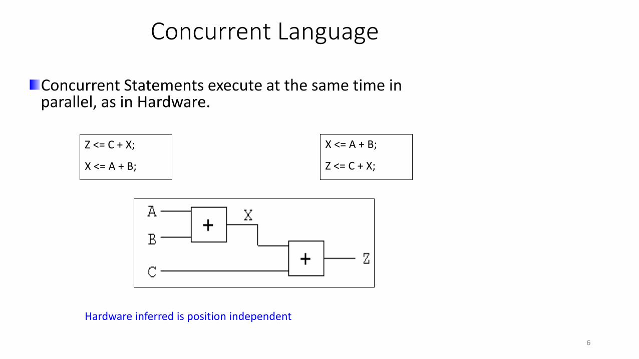
Concurrent Statements execute at the same time in parallel, as in Hardware.
Z <= C + X;
X <= A + B;
X <= A + B;
Z <= C + X;
Hardware inferred is position independent
6

Sequential Language
Sequential Statements execute one at a time in sequence.
As the case with any conventional language
Sequence of statements is important.
7
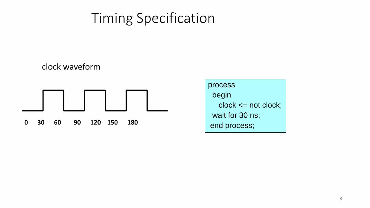
Timing Specification
clock waveform
0 30 60 90 120 150 180
process
begin
clock <= not clock;
wait for 30 ns;
end process;
8

Test Language
Test bench
- Is part of a VHDL model that generates a set of test vectors and
sends them to the Module being tested.
- Collects the responses made by the Module Under Test and
compares them against a specification of correct results.
Need
To ensure that design is correct.
Model is operating as required.
9

Design Hierarchy
Hierarchy can be represented using VHDL.
Consider example of a Full-adder which is the top level module, being composed of three lower level modules i.e. Half-Adder and OR gate.
10

History of VHDL
In 1981 the Institute for Defense Analysis (IDA) had arranged a workshop to study • Various Hardware Description methods• Need for a standard language• Features required by such a standard.
A team of three companies, IBM, Texas Instruments, and Intermetrics were awarded contract by DoD to develop a language.
Version 7.2 of VHDL was released along with Language Reference Manual (LRM) in 1985.
Standardized by IEEE in 1987 known as the IEEE Std 1076-1987.
11
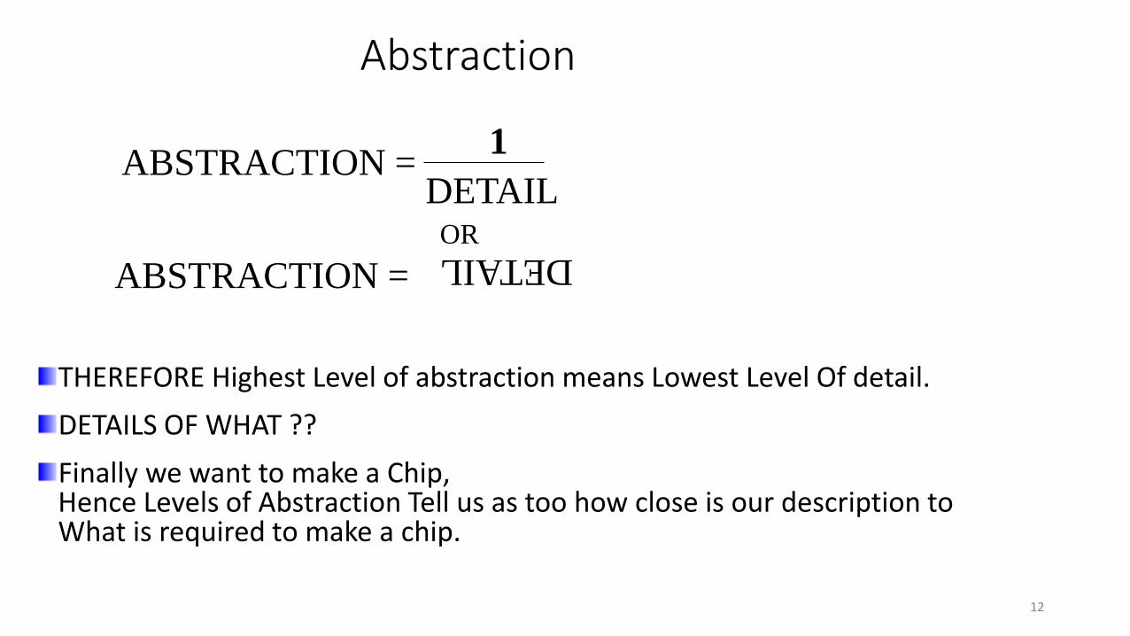
Abstraction
DETAIL
ABSTRACTION =DETAIL
1
OR
ABSTRACTION =
THEREFORE Highest Level of abstraction means Lowest Level Of detail.
DETAILS OF WHAT ??
Finally we want to make a Chip, Hence Levels of Abstraction Tell us as too how close is our description to What is required to make a chip.
12
Levels of Abstraction
Different styles are adopted for writing VHDL code.
Abstraction defines how much detail about the design is specified in a particular description.
There are four main levels of Abstraction.
• Layout Level
• Logic level
• Register Transfer Level
• Behavioral Level
13

Layout Level
Lowest level of Abstraction.
Specifies –Actual layout of design on Silicon
Contains –Detailed timing information, and analog effects.
14
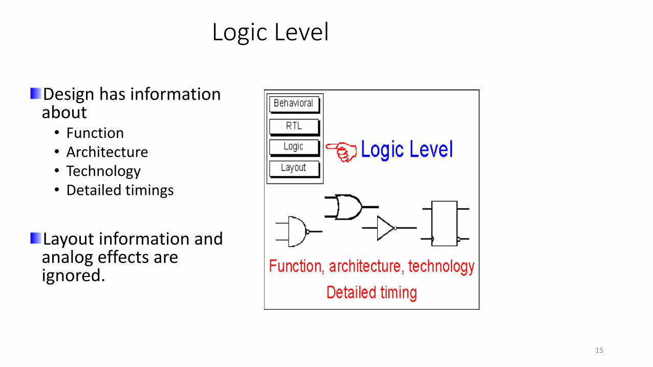
Logic Level
Design has information about
• Function• Architecture• Technology • Detailed timings
Layout information and analog effects are ignored.
15

Register Transfer Level
Using HDLs every register in the design, and the logic in between is defined
Design contains • Architecture information• No details of Technology• No specification of
absolute timing delays.
16

Register Transfer Level
Entire Design is partitioned between clocked and combinational processes. E.g. up down / synchronous counter
17
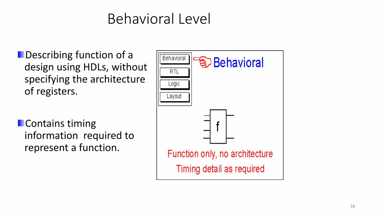
Behavioral Level
Describing function of a design using HDLs, without specifying the architecture of registers.
Contains timing information required to represent a function.
18

Behavioral Level
Behavioral Model of an AND gate.
architecture and_gate_arch of and_gate is
begin
process(a,b)
begin
if (a = '1' and b = '1') then
c <= '1';else
c <= '0';
end if;end process;
end and_gate_arch;
19

Basic Building Blocks
ENTITY • A design’s interface to the external circuitry.
ARCHITECTURE• Describes a design’s behavior and functionality.
CONFIGURATION• Binds an entity to an architecture when there are multiple architectures for a single entity.
LIBRARY – Library should be declared before EACH entity declaration even if it is in the same VHDL file.
• Is a collection of compiled VHDL units• Commonly used functions, procedure and user data types can be compiled into a user-
defined library for use in all designs
library IEEE;
use IEEE.std_logic_1164.all;
use IEEE.std_logic_unsigned.all;
Syntax
20

Entity
Equivalent to pin configuration of an IC.
Syntax:
entity entity_name is
port (port_list) ;
end entity_name;
Example :
entity and_gate is
port ( 1A, 2A, 3A, 4A : in std_logic;
1B, 2B, 3B, 4B : in std_logic;
1Y, 2Y, 3Y, 4Y : out std_logic
) ;
end and_gate ;
21
Entity
VHDL design description must include,• ONLY ONE ENTITY
Entity Declaration• Defines the input and output ports of the design.• Each port in the port list must be given,
a name
data flow direction
a type.
Can be used as a component in other entities after being compiled into a library.
22
Entity
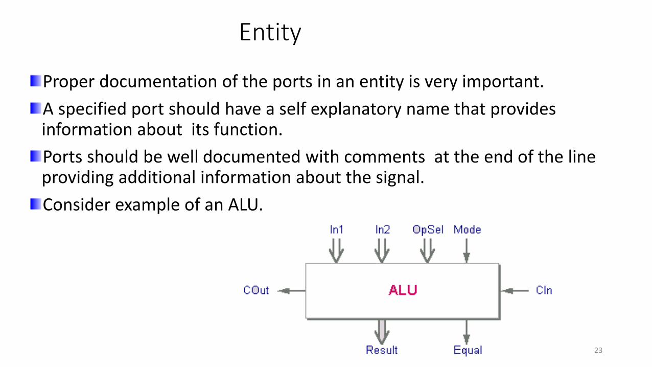
Proper documentation of the ports in an entity is very important.
A specified port should have a self explanatory name that provides information about its function.
Ports should be well documented with comments at the end of the line providing additional information about the signal.
Consider example of an ALU.
23
Entity
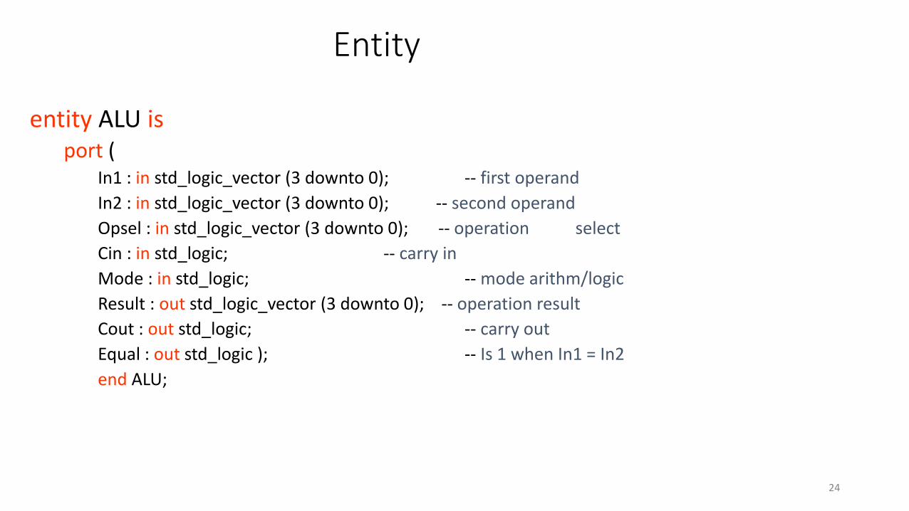
entity ALU is port (
In1 : in std_logic_vector (3 downto 0); -- first operand
In2 : in std_logic_vector (3 downto 0); -- second operand
Opsel : in std_logic_vector (3 downto 0); -- operation select
Cin : in std_logic; -- carry in
Mode : in std_logic; -- mode arithm/logic
Result : out std_logic_vector (3 downto 0); -- operation result
Cout : out std_logic; -- carry out
Equal : out std_logic ); -- Is 1 when In1 = In2
end ALU;
24

Modes
Signal in the port has a Mode which indicates the driver direction.
Mode also indicates whether or not the port can be read from within the entity.
Four types of Modes are used in VHDL.• Mode IN• Mode OUT• Mode INOUT• Mode BUFFER
25

Mode IN
Value can be read but not assigned.
Example:
entity driver is
port ( A : in std_logic;
) ;
end driver ; Drivers reside outside the entity
Port Signal Entity
26

Mode OUT
Drivers reside inside the entity
Value can be assigned but not read.
Example:
entity driver is
port ( B : out std_logic;
) ;
end driver ;
Port SignalEntity
27
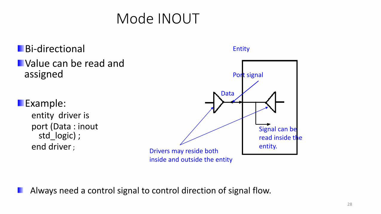
Mode INOUT
Always need a control signal to control direction of signal flow.
Bi-directional
Value can be read and assigned
Example:entity driver isport (Data : inout
std_logic) ;end driver ;
Entity
Drivers may reside bothinside and outside the entity
Port signal
Signal can be read inside the entity.
Data
28

Mode BUFFER
Output port with Internal read capability
Example:
entity driver is
port (Count : buffer std_logic ) ;
end driver ;
Count
Entity
Driver resideInside the entity
Signal inside can beread inside the entity
Note – does not exists in real life hardware but are included for
convenience.29

Architecture
Specifies,
• Behavior
• Function
• Relationship between inputs and outputs of an entity.
Syntax:
architecture architecture_name of entity_name is
declarations
begin
concurrent_statements
end [ architecture_name ];
30
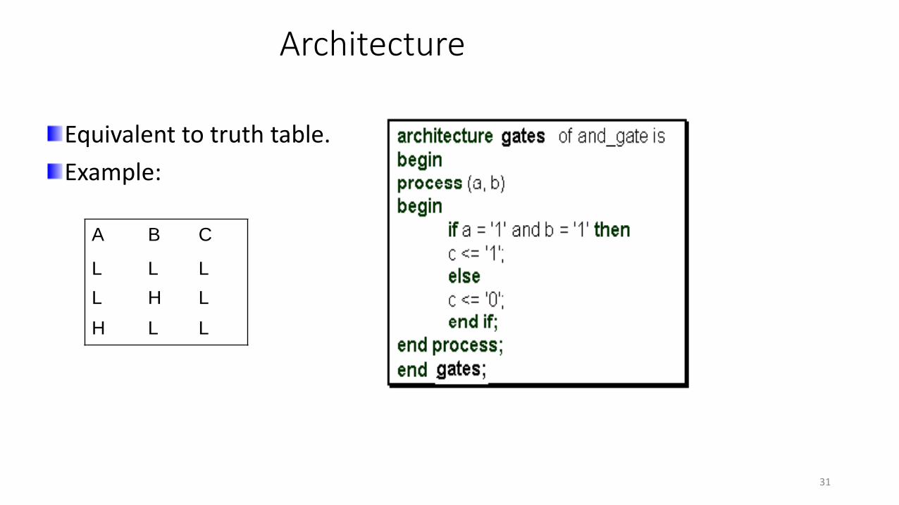
Architecture
Equivalent to truth table.
Example:
A B C
L L L
L H L
H L L
31

Architecture
Can contain only Concurrent Statements.
A design can be described in an Architecture using various Levels of Abstraction.
• To facilitate faster design• Better understanding• Lesser complexity.
AN ENTITY CAN HAVE MORE THAN ONE ARCHITECTURE!!
There can be no architecture without an Entity.
32

Architecture Bodies
Behavioral
• Also known as High-level Descriptions.
• Consists of a set of assignment statements to represent behavior.
• No need to focus on the gate-level implementation of a design.
33
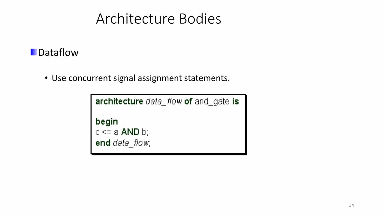
Architecture Bodies
Dataflow
• Use concurrent signal assignment statements.
34

Architecture Bodies
Structural
• Components from libraries are connected together.
• Designs are hierarchical.
• Each component can be individually simulated.
• Consists of VHDL netlists.
It is possible to mix the three Modeling styles in a single architecture body.
35

Comparing Architectural Bodies
A structural design methodology is used to
• Split a design into manageable units.
• Silicon vendors provide libraries which can be used to instantiate components that represent device-specific resources and optimized structures.
• eg. LogiBLOX in Xilinx Tool.
• Synthesis tools have in-built algorithms that find the optimal solution regardless of the form of description.
36

Configuration
NEED:
37

Configuration
Configuration declaration is used to select one of the many architectures that an entity may have.
Syntax:
configuration configuration_name of entity_name is
for architecture_name
for instantiation:component_name
use library_name.entity_name(architecture_name);
end for;
end for;
end configuration_name;38

Configuration
entity gates is
port (
a,b : in STD_LOGIC;
c: out STD_LOGIC );
end gates;
architecture and2_arch of gates is
begin
c <= a and b;
end and2_arch;
architecture or2_arch of gates is
begin
c <= a or b;
end or2_arch;
configuration and_or of gates is
for and2_arch;
end for;
39
Language Elements
VHDL is a strongly TYPED Language.
VHDL is not case sensitive.
VHDL supports a variety of data types and operators.
• OBJECTS
• OPERATORS
• AGGREGATES
40
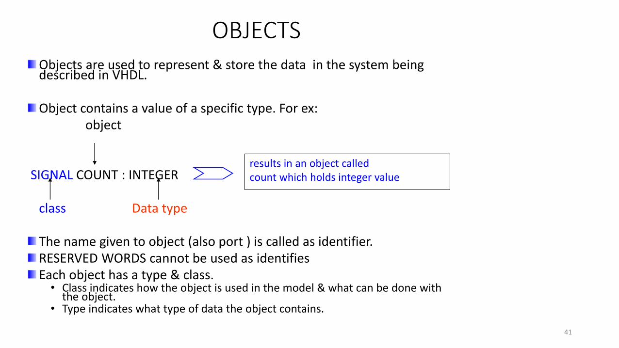
OBJECTSObjects are used to represent & store the data in the system being described in VHDL.
Object contains a value of a specific type. For ex:object
SIGNAL COUNT : INTEGER
class Data type
The name given to object (also port ) is called as identifier.RESERVED WORDS cannot be used as identifiesEach object has a type & class.
• Class indicates how the object is used in the model & what can be done with the object.
• Type indicates what type of data the object contains.
results in an object calledcount which holds integer value
41

OBJECTS
Each object belong to one of the following
CLASS
CONSTANT SIGNAL VARIABLE
The set of values that each object can hold is specified by DATA TYPES
SCALAR ACCESS FILE COMPOSITE
Integer Real Enumerated Physical Array
42

CONSTANTS
These are identifiers with fixed value.
The value is assigned only once, when declared.
Value cannot be changed during simulation.
Example:
constant Bus_Width : Integer := 16;
constant CLK_Period : Time := 15 ns;
Constants makes the design description more readable.
Design changes at later time becomes easy.
43

Scalar data types Enumerated
This declaration defines a set of user-defined values consisting of identifiers & character literals.
User defined enumeration• type micro_op is ( load, store, add, sub, mul, div )
• As shown micro_op is enumerated types & supports the values load, store, add & sub.
• Values of enumeration type has position number associated with them. Compiler encodes these enumeration literals in ascending order.
Predefined enumeration types :• Bit :Supports the values ‘0’ & ‘1’.
• Boolean : Supports literals FALSE & TRUE is defined as
variable error_flag : boolean := true.• Std_logic_type : Data type defined in the std_logic_1164 package of
IEEE library. It is defined astype std_logic is (‘U’, ‘X’, ‘0’, ‘1’, ‘Z’, ‘W’, ‘L’, ‘H’);
44

SCALAR DATA TYPES
Data type Meaning Example
Integer Has set of values that
follow within specific range
signal count : integer range 0
to 8
Real Has a set of values in
given range of real
numbers.
signal real_data : real range
0.0 to 35.5
Physical Used to represent physical
quantities such as current,
time distance
Constant set_up : time := 2 ns.
OBJECTS OF PHYSICAL TYPE ARE NOT SYNTHESISABLE ??
45

COMPOSITE DATA TYPES
Composite Data Types represents collection of values.
ARRAY - : Consists of the elements that have same type.
• Vector ( special case of single dimensional array )
Ex signal A : std_logic_vector (7 downto 0);
• Two dimensional array (typical application is a memory device)
• Ex : type memory_1K4 is array ( 0 to 1023 ) of std_logic_vector
( 3 downto 0);signal memory : memory_1K4
46

Operators
Logical Operators Lowest priority (except “not”) ??
Relational Operators
Shift Operators
Adding Operators
Multiplying Operators
Miscellaneous Operators Highest priority
47
Logical Operators
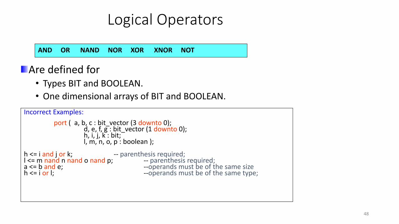
AND OR NAND NOR XOR XNOR NOT
Are defined for • Types BIT and BOOLEAN.
• One dimensional arrays of BIT and BOOLEAN.
Incorrect Examples:
port ( a, b, c : bit_vector (3 downto 0);d, e, f, g : bit_vector (1 downto 0);h, i, j, k : bit;l, m, n, o, p : boolean );
h <= i and j or k; -- parenthesis required;l <= m nand n nand o nand p; -- parenthesis required;a <= b and e; --operands must be of the same sizeh <= i or l; --operands must be of the same type;
48

Relational ( Conditional ) Operators
Are used to check conditions.
“=“ and “/=“ are predefined for all types.
“<“, “<=“, “>”, and “>=“ are predefined for• For integer types
• Enumerated types
• One-dimensional arrays of enumeration and integer types.
= /= < > <= >=
49

Relational Operators
No numerical meaning is associated with a BIT vector
Elements of a vector are just a collection of objects of the same type.
For array types operands are aligned to the left and compared to the right.
50
Shift Operators – VHDL 93
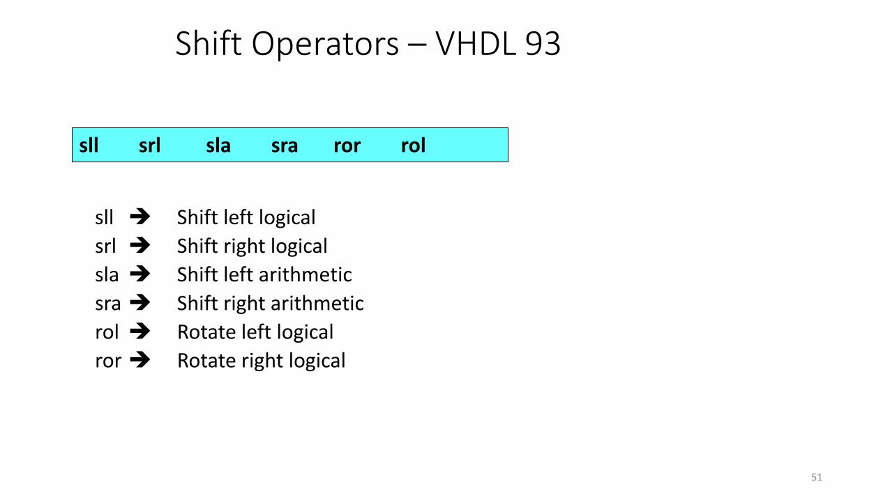
sll srl sla sra ror rol
sll Shift left logical
srl Shift right logical
sla Shift left arithmetic
sra Shift right arithmetic
rol Rotate left logical
ror Rotate right logical
51

Shift Operators
Each operator Takes an array of BIT or BOOLEAN as the left operand
Integer value as the right operand
Ex: ‘A’ is a bit_vector equal to “10010101”A sll 2 is “01010100” (shift left logical, filled with ‘0’)
A srl 3 is “00010010” (shift right logical, filled with ‘0’)
A sla 3 is “10101111” (shift left arithmetic, filled with right bit )
A sra 2 is “11100101” (shift right arithmetic, filled with left bit )
A rol 3 is “10101100” (rotate left)
A ror 2 is “01100101” (rotate right)
52

Adding Operators
+ - &Addition subtraction concatenation
Concatenation Operator (&)Operands can be one-dimensional array type or element type“&” Operator works on vectors only.
Example:signal a: std_logic_vector ( 5 downto 0 );signal b,c,d: std_logic_vector ( 2 downto 0 );beginb <= ‘0’ & c(1) & d(2);a <= c & d;end;
53

Adding Operators
Do not use Concatenation operator on the left of the assignment symbol.
architecture bad of ex is signal a : std_logic_vector ( 2 downto 0 );
signal b : std_logic_vector ( 3 downto 0 );
begin
‘0’ & a <= b; -- Error!
end bad;
54

Multiplying Operators
* / mod rem
( * ) and ( / ) are predefined for: Integers, Floating point numbers
mod ( modulus ) and rem ( remainder ) are predefined for Integers only.
Example:
variable A,B : Integer;
Variable C : Real;
C <= 12.34 * ( 234.4 / 43.89 );
A <= B mod 2;
55
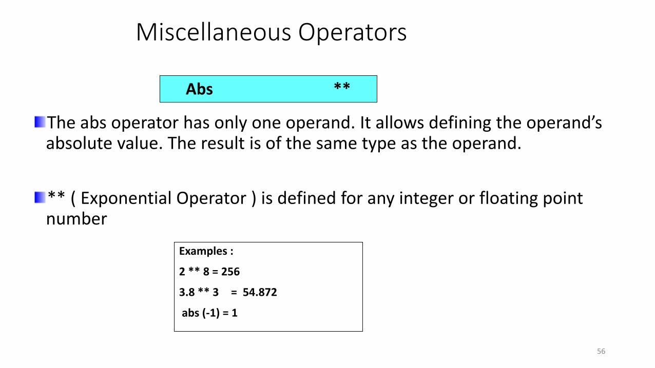
Miscellaneous Operators
The abs operator has only one operand. It allows defining the operand’s absolute value. The result is of the same type as the operand.
** ( Exponential Operator ) is defined for any integer or floating point number
Abs **
Examples :
2 ** 8 = 256
3.8 ** 3 = 54.872
abs (-1) = 1
56

Aggregates
Assigns values to the elements of an array.Example :
a <= ( others => ‘0’; ) identical to a <= “00000”
We can assign values to some bits in a vector and use “others” clause to assign the remaining bits.
Example:a <= ( 1=>’1’, 3=>’1’, others =>’0’ );signal data_bus : std_logic_vector ( 15 downto 0 );data_bus <= ( 14 downto 8 => '0', others => '1‘ );
57

Aggregates
Elements in a vector can also be assigned values of other signals.
Example : “a” has a length of 5 bits.
a <= (1=> c(2), 3=> c(1), others => d(0); identical to a <= c(2) & d(0) & c(1) & d(0) & d(0) ; ------( Disadvantage ? )
“others” choice can be only the last choice in an aggregate.
Each element of the value defined by an aggregate must be represented ONCE AND ONLY ONCE in the aggregate.
58

Concurrent Statements
MEANING IN HARDWARE TERMS
CONCURRENT CONSTRUCTS• WHEN_ELSE STATEMENT• WITH_SELECT STATEMENT
COMPONENT INSTANTIATION• USE OF GENERATE STATEMENT
CONCURRENT STATEMENT CHARACTERISTICS
59

Concurrent Statements
ConsiderX = X+Y;
In software:• X and Y are register
locations
• The contents of X and Y are added and the result is stored in X.
60

Concurrent Statements
In concurrent statements, there are no implied registers.
Feedback is described around Combinational logic.
61

Selected Signal Assignment – ‘when’ statement
Z <= A when x = ‘0' and y = ‘0' else
B when x = ‘0’ and y = ‘1’else
C;
0
1
2
3
A
B
C
>
>
>
z
62

Selected Signal Assignment – ‘when’ statement
Z <= A when x = ‘0' else
B when y = ‘0' else
C;
0
1
>A
z
x
??
63

Selected Signal Assignment – ‘when’ statement
Z <= A when x = ‘0' else
B when y = ‘0' else
C;
0
1
>A
z
x
0
1
y
B
C
>
>
64

Selected Signal Assignment – ‘when’ statement
Modeling Tri-state buffer
architecture tri_ex_a of tri_ex is
begin
out1 <= in1 when control = '1' else
'Z';
end tri_ex_a;
65

Selected Signal Assignment – ‘with’ statement
Syntax
‘with...select’ statement evaluates choice_expression and compares that value to each choice value.
In ‘when’ statement the matching choice value has its expression assigned to target.
Each value in the range of the choice_expression type must be covered by one choice.
with choice_expression select
target <= expression 1 when choice 1;
expression 2 when choice 2;
expression N when choice N ;
66

Selected Signal Assignment – ‘with’ statement
signal A, B, C, D, Z: std_logic;
signal CONTROL: std_logic_vector (1 downto 0);
with CONTROL select
Z <= A when "00",
B when "01",
C when "10",
D when "11";
‘0’ when others;
Why “when others” clause?
• No two choices can overlap.
• All possible choices must be enumerated.
• Each choice can be either a static expression (such as 3) or a static
range (such as 1 to 3).
67

Selected Signal Assignment – ‘with’ statement
architecture with_ex_a of with_ex is
begin
with in1 select
out1 <= in2 when '1',
'0' when others;
end with_ex_a;
Modeling multiplexer
68

Design Hierarchy
Hierarchy can be implemented using VHDL. Predefined design can be used to model complex functionality.
Full adder can be implemented using two half adders as shown below
A SU1
B C
A SU2
B C
IN1
IN2
IN3
sum
carry
Top level
Component
69

Design Hierarchyentity half is
port ( A,B : in BIT; S1,Carry : out BIT);
end half;
architecture add_arch of half is
component xor
port ( A,B : in BIT; C : out BIT);
end component;
component nd2
port ( A,B : in BIT; C : out BIT);
end component
signal s1,c1, c2 : BIT;
begin
U1: xor port map (A => a, B =>b, S => S1);
U2: ND2 port map ( A =>a, B =>b, C=>carry);
70
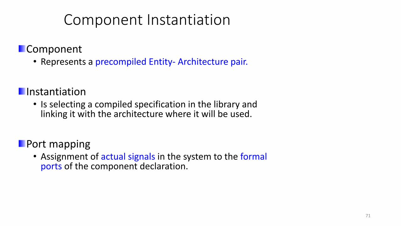
Component Instantiation
Component• Represents a precompiled Entity- Architecture pair.
Instantiation • Is selecting a compiled specification in the library and
linking it with the architecture where it will be used.
Port mapping • Assignment of actual signals in the system to the formal
ports of the component declaration.
71

Component Instantiation
instance_name : component_name
port map (
[ port_name => ] expression
[port_name => ] expression );
Syntax:
instance_name names this instance of the component type by component_name - WHY?
port map connects each port of this instance of component_name to a signal-valued expression in the current entity.
72

Component Instantiation
entity ND4 ISport ( IN1,IN2,IN3,IN4 : in BIT;
Z : out BIT);
end ND4;
architecture gate_arch of ND4 iscomponent ND2
port ( A, B: in BIT; C : out BIT);
end component;signal TEMP_1,TEMP_2 : BIT;beginU1: ND2 port map ( A =>IN1, B =>IN2, C=>TEMP1 );U2: ND2 port map ( A =>IN3, B =>IN4, C=>TEMP2 );U3: ND2 port map ( A =>TEMP1, B =>TEMP2, C=>Z );
73

Component Instantiation
Ports can be mapped to signals by ‘Positional’ or ‘mixed’ notation.
U1: ND2 port map ( IN1,IN2, TEMP_1 ); -- positional
U2: ND2 port map (A => X, C => Z, B => Y); -- Named
U3: ND2 port map (IN1,IN2, C => TEMP1); -- Mixed
Named association is preferred because it makes the code more readable and pins can be specified in any order.
All positional connections should be placed before any named connections.
74

Generate Statement
Concurrent statements can be conditionally selected or replicated using “generate” statement.
Used to create multiple copies of components, processes, or blocks.
• For ex: Provides a compact description of regular structures such as memories, registers, and counters.
No simulation semantics are associated.
75
Generate Statement
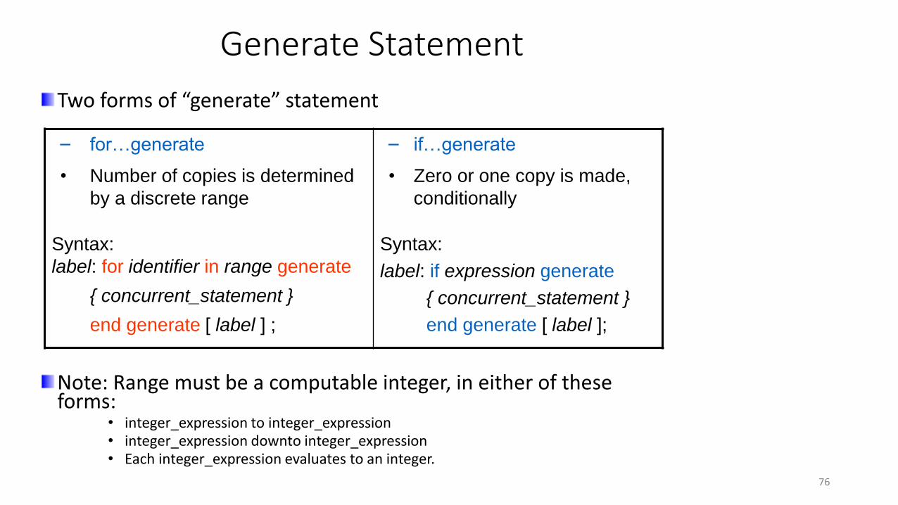
Two forms of “generate” statement
Note: Range must be a computable integer, in either of these forms:
• integer_expression to integer_expression• integer_expression downto integer_expression• Each integer_expression evaluates to an integer.
– for…generate
• Number of copies is determined
by a discrete range
Syntax:
label: for identifier in range generate
{ concurrent_statement }
end generate [ label ] ;
– if…generate
• Zero or one copy is made,
conditionally
Syntax:
label: if expression generate
{ concurrent_statement }
end generate [ label ];
76

Generate Statement
for….generateExample:
77
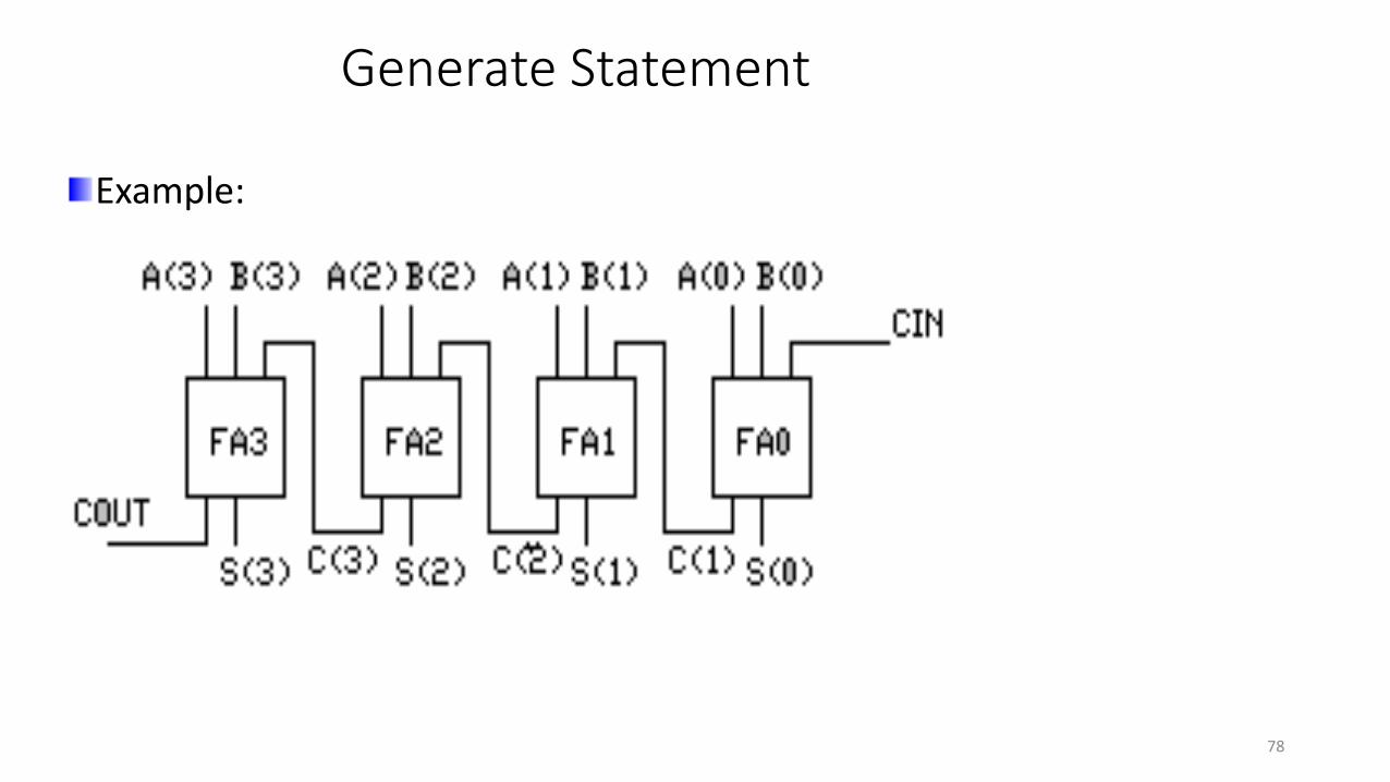
Generate Statement
Example:
78

Generate Statement
if…generate
Example:
79

Generate Statement
Example:
80

Drivers
Are created by signal assignment statements
Concurrent signal assignment produces one driver for each signal assignment
81
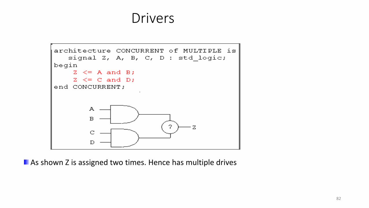
Drivers
As shown Z is assigned two times. Hence has multiple drives
82
Drivers
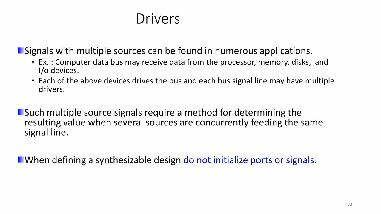
Signals with multiple sources can be found in numerous applications.• Ex. : Computer data bus may receive data from the processor, memory, disks, and
I/o devices.• Each of the above devices drives the bus and each bus signal line may have multiple
drivers.
Such multiple source signals require a method for determining the resulting value when several sources are concurrently feeding the same signal line.
When defining a synthesizable design do not initialize ports or signals.
83
Resolution Function
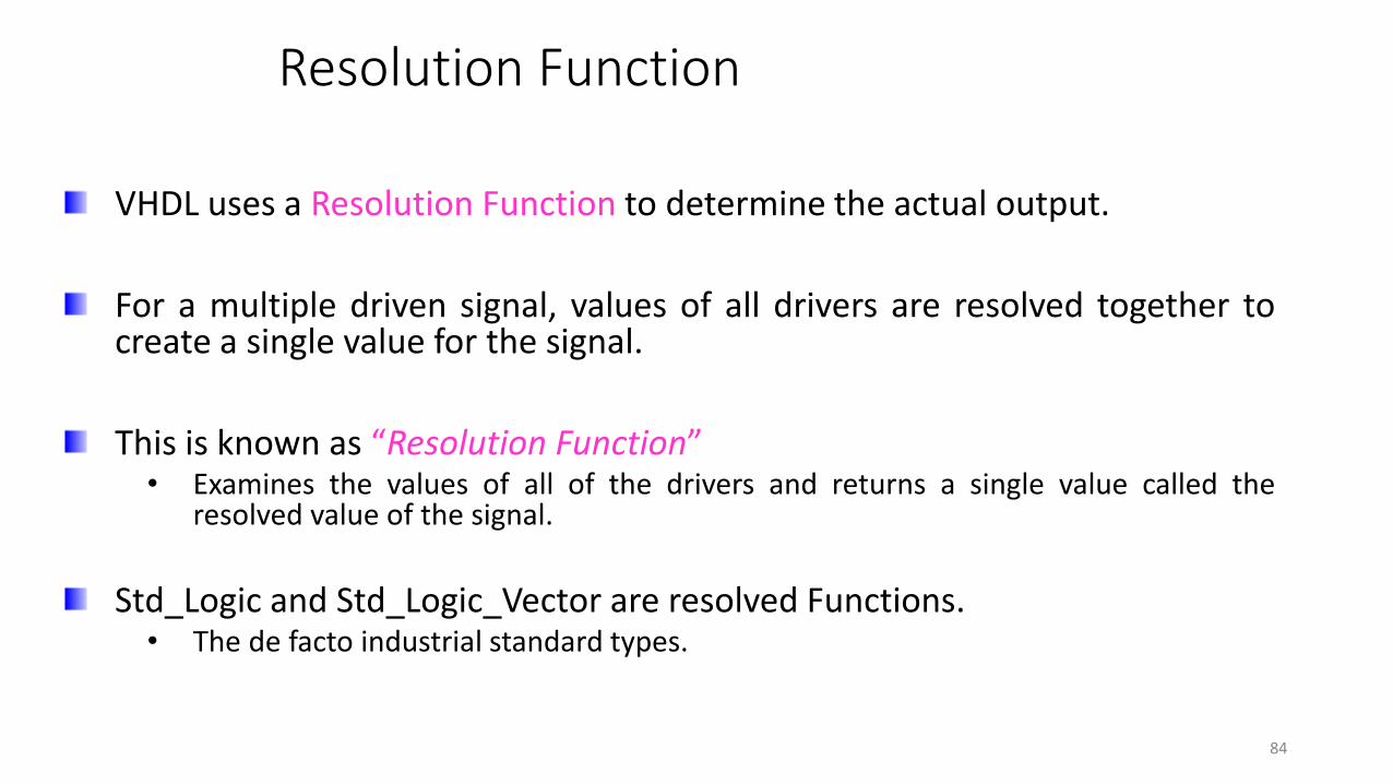
VHDL uses a Resolution Function to determine the actual output.
For a multiple driven signal, values of all drivers are resolved together tocreate a single value for the signal.
This is known as “Resolution Function”• Examines the values of all of the drivers and returns a single value called the
resolved value of the signal.
Std_Logic and Std_Logic_Vector are resolved Functions.• The de facto industrial standard types.
84
Resolution Function
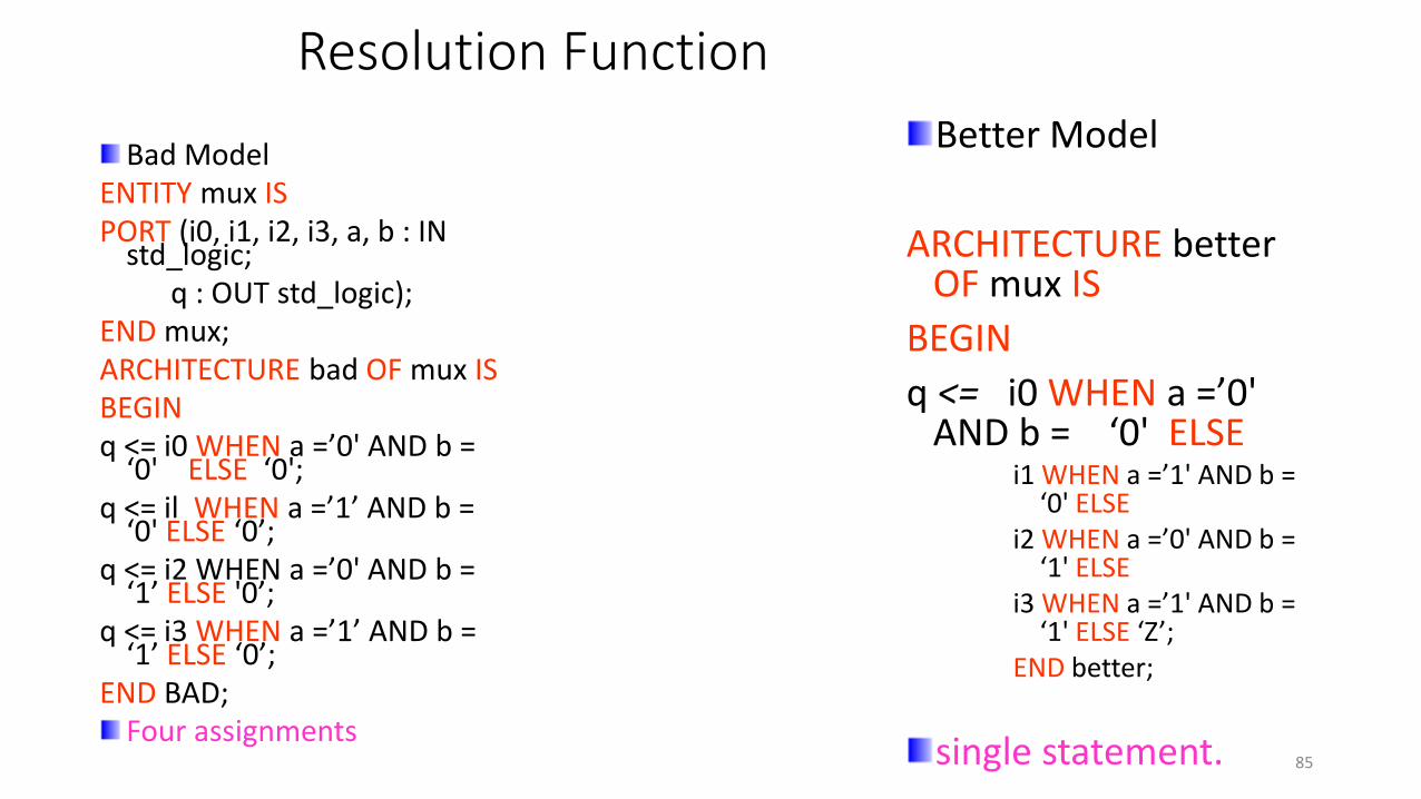
Better Model
ARCHITECTURE better OF mux IS
BEGIN
q <= i0 WHEN a =’0' AND b = ‘0' ELSE
i1 WHEN a =’1' AND b = ‘0' ELSE
i2 WHEN a =’0' AND b = ‘1' ELSE
i3 WHEN a =’1' AND b = ‘1' ELSE ‘Z’;
END better;
single statement.
Bad ModelENTITY mux ISPORT (i0, i1, i2, i3, a, b : IN
std_logic;q : OUT std_logic);
END mux;ARCHITECTURE bad OF mux ISBEGINq <= i0 WHEN a =’0' AND b =
‘0' ELSE ‘0';q <= il WHEN a =’1’ AND b =
‘0' ELSE ‘0’;q <= i2 WHEN a =’0' AND b =
‘1’ ELSE '0’;q <= i3 WHEN a =’1’ AND b =
‘1’ ELSE ‘0’;END BAD;
Four assignments85

SEQUENTIAL STATEMENTS
HOW DOES PROCESS WORK?
SEQUENTIAL CONSTRUCTS• IF STATEMENT• CASE STATEMENT
TYPES OF PROCESSES
HARDWARE MODELING EXAMPLES
SEQUENTIAL STATEMENTS CHARACTERISTICS
WAIT STATEMENT
LOOP STATEMENTS
86

Process Statement – characteristics
Are executed one after another, in the order in which they are written.
Can appear only in a Process.
Only sequential statements can use Variables.
“Process” is the primary concurrent VHDL statement used to describe sequential behavior.
Statements in a process, are executed sequentially in zero time.
All processes in an architecture behave concurrently.
Process repeats forever, unless suspended.
NOTE : SEQUENTIAL STATEMENTS DO NOT GENERATE SEQUENTIAL HARDWARE
87

Sensitivity List
Simulator runs a process when any one of the signals in the sensitivity list changes.
Process should either have a “sensitivity list” or a “wait” statement at the end.
Only static signal names for which reading is permitted may appear in the sensitivity list of a process statement.
The execution of a process statement consists of the repetitive execution of its sequence of statements.
88

If Statement
if condition1 then
{ sequential_statement }
elsif condition2 then
{ sequential_statement }
else
{ sequential_statement }
end if;
Syntax:
“If “ Statement evaluates each condition in order.
Statements can be nested.
Generates a priority structure.
Corresponds to “when-else” command in the concurrent part.
89

if Statement
Avoid using more than three levels of If…else statements .
When defining the condition, use parentheses to differentiate levels of operations on the condition.
90

If statement
process (sel, a, b, c, d)
begin
If sel(2) = ‘1’ then
y <= A;
elsif sel(1) = ‘1’ theny <= B;
elsif sel(0) = ‘1’ theny <= C;
else y <= D;
end if;
end process; • Generates a priority structure.
• Corresponds to “when-else” command in
the concurrent part.
91
Case Statement
Syntax:
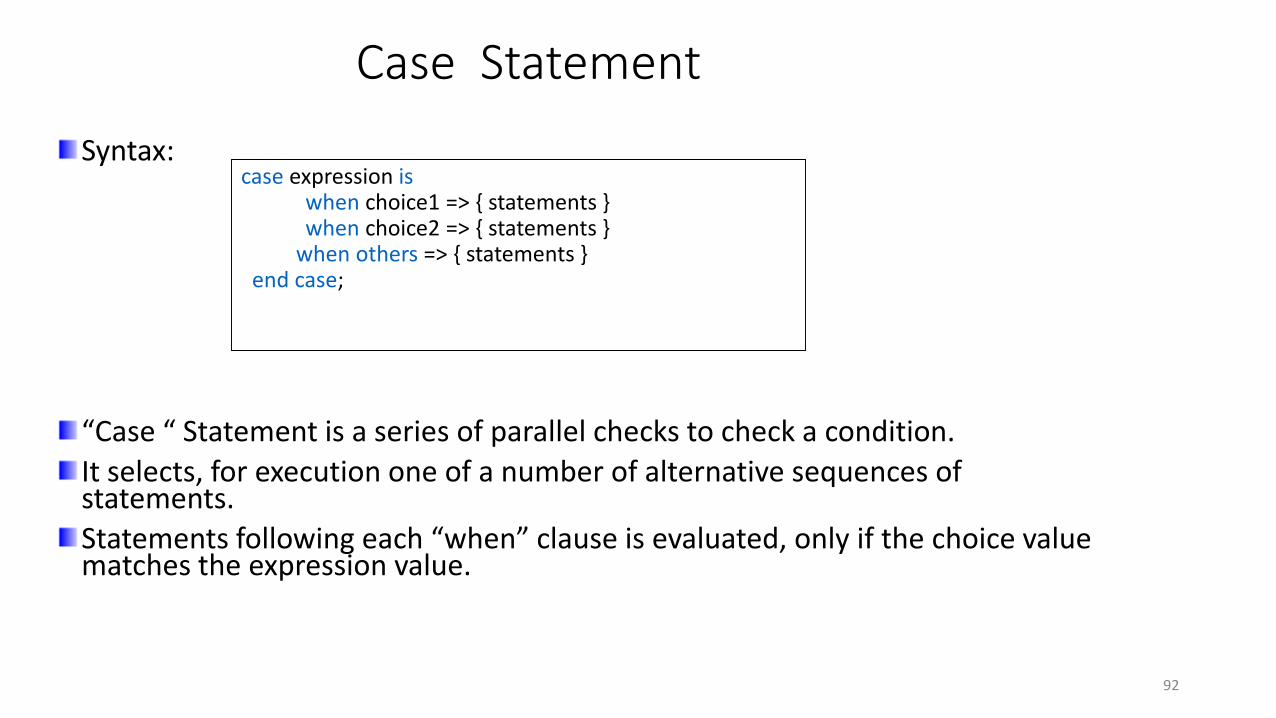
“Case “ Statement is a series of parallel checks to check a condition.
It selects, for execution one of a number of alternative sequences of statements.
Statements following each “when” clause is evaluated, only if the choice value matches the expression value.
case expression iswhen choice1 => { statements }when choice2 => { statements }
when others => { statements } end case;
92
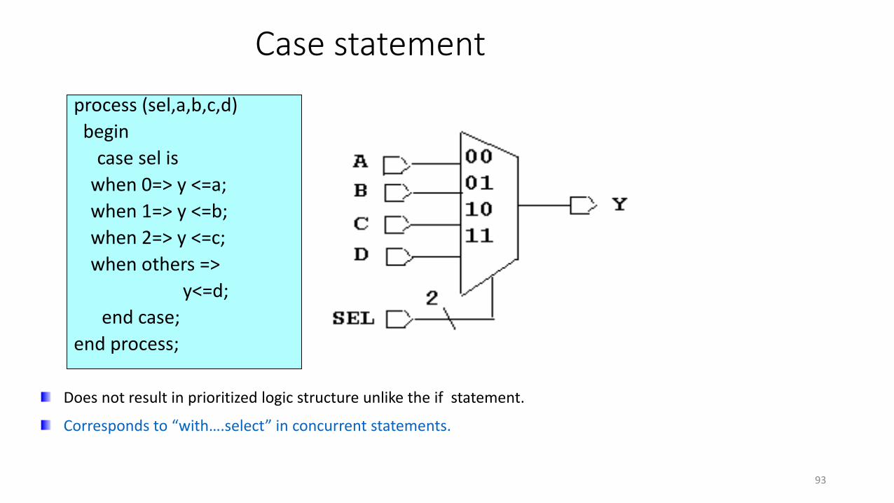
Case statement
process (sel,a,b,c,d)
begin
case sel is
when 0=> y <=a;
when 1=> y <=b;
when 2=> y <=c;
when others =>
y<=d;
end case;
end process;
Does not result in prioritized logic structure unlike the if statement.
Corresponds to “with….select” in concurrent statements.
93
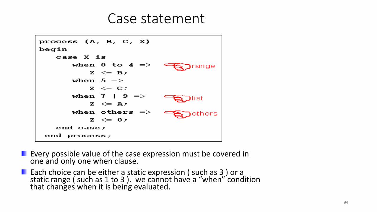
Case statement
Every possible value of the case expression must be covered in one and only one when clause.
Each choice can be either a static expression ( such as 3 ) or a static range ( such as 1 to 3 ). we cannot have a “when” condition that changes when it is being evaluated.
94
Invalid “Case” Statements
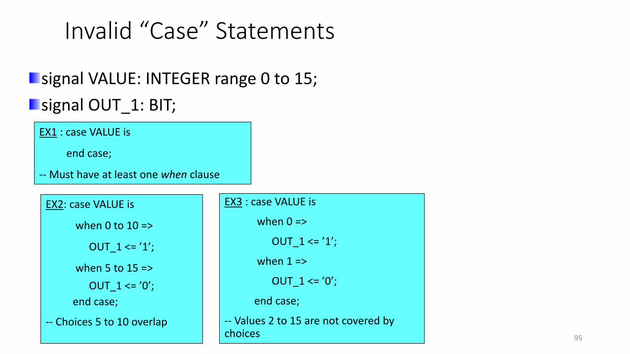
signal VALUE: INTEGER range 0 to 15;
signal OUT_1: BIT;
EX1 : case VALUE is
end case;
-- Must have at least one when clause
EX2: case VALUE is
when 0 to 10 =>
OUT_1 <= ’1’;
when 5 to 15 =>
OUT_1 <= ’0’;
end case;
-- Choices 5 to 10 overlap
EX3 : case VALUE is
when 0 =>
OUT_1 <= ’1’;
when 1 =>
OUT_1 <= ’0’;
end case;
-- Values 2 to 15 are not covered by choices 95

Null Statement
Does not perform any action
Can be used to indicate that when some conditions are met no action is to be performed
Example: case a is
when “00” => q1 <= ‘1’;
when “01” => q2 <= ‘1’;
when “10” => q3 <= ‘1’;
when others <= null; ----------------------Why?
end case;
96
Comparing “if” and “Case” Statements
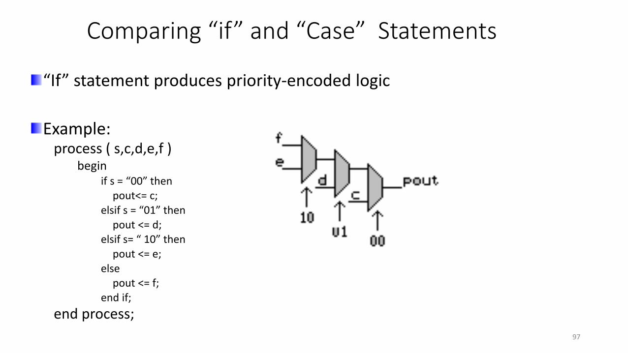
“If” statement produces priority-encoded logic
Example:process ( s,c,d,e,f )
beginif s = “00” then
pout<= c;elsif s = “01” then
pout <= d;elsif s= “ 10” then
pout <= e;else
pout <= f;end if;
end process;
97

Comparing “if” and “Case” Statements
“Case” statement produces parallel logic
Example
process ( s, c, d, e, f )begin
case s iswhen “00” =>
pout <= c;when “01” =>
pout <= d;when “10” =>
pout <= e;when others =>
pout <= f;end case;
end process;98

Process statement
Two types of processes:• Combinatorial
• Clocked
Combinatorial Process • Generates combinational logic
• All inputs must be present in the sensitivity list.
process (a,b,c)
begin
x <=( a and b) or c;
end process;
99
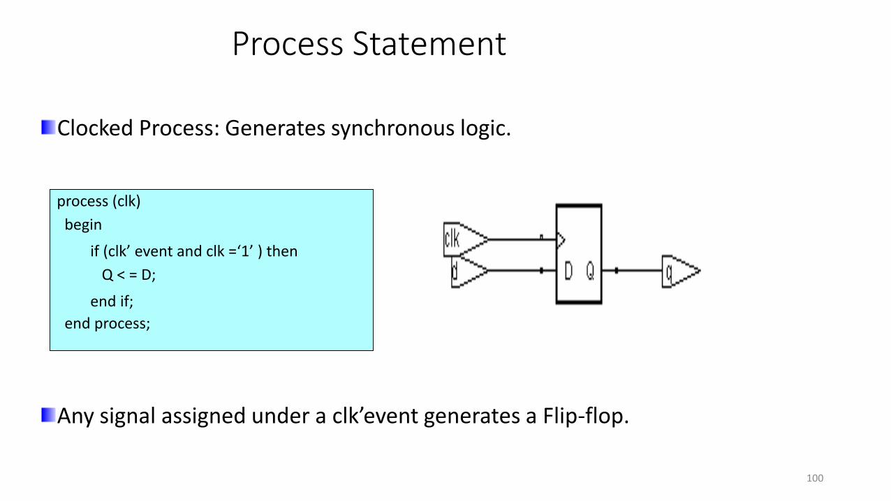
Process Statement
Clocked Process: Generates synchronous logic.
Any signal assigned under a clk’event generates a Flip-flop.
process (clk)
begin
if (clk’ event and clk =‘1’ ) then
Q < = D;
end if;
end process;
100
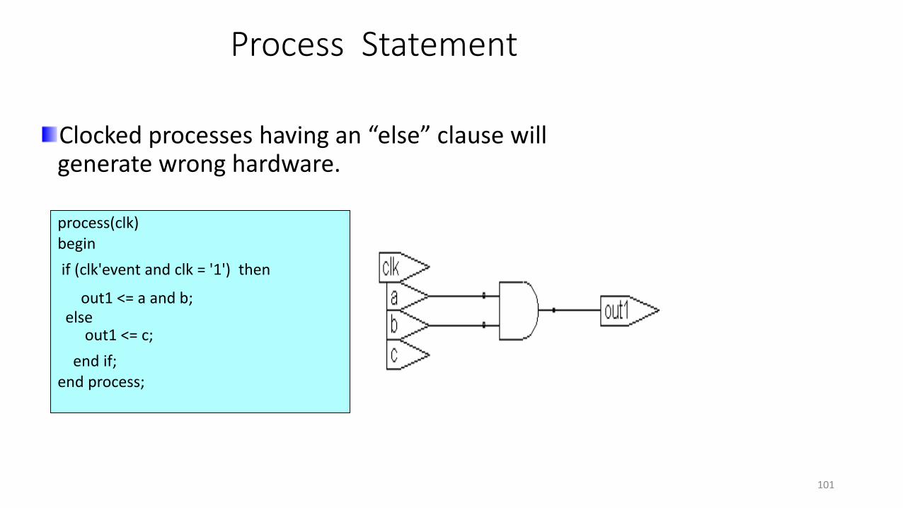
Process Statement
Clocked processes having an “else” clause will generate wrong hardware.
process(clk)begin
if (clk'event and clk = '1') then
out1 <= a and b;else
out1 <= c;
end if;end process;
101

Hardware Modeling Examples
Flip-flops should be reset or preset to a value on start-up
because:
- Initial state of the flip-flop may not be known after power-up.
- Initial state of the flip-flop may not be the desired value after
power-up.
- To place the system into a known state during operation.
102

Implement a D flip–flop with two outputs complemented & uncomplemented
Process(CLK)begin
If CLK=‘1’ and CLK’event then Q <= D;Qbar <= not D;
end if;end process;
Process(CLK)begin
If CLK=‘1’ and CLK’event then Q <= D;Qbar <= not Q;
end if;end process;
Bad coding style infers two flip-flops
Process(CLK) begin
If CLK=‘1’ and CLK’event then Q <= D;
end if;end process;Qbar <= not D;
Good coding style
103

Hardware Modeling Examples
Synchronous Reset : Flip-flops are reset on the active edge of the clock when reset is held active.
process (CLK)
begin
if ( CLK’ event and CLK = ‘1’) then
if ( RST = ‘1’ ) then
Q <= ‘0’;else
Q <= D;
end if;
end if;end process;
104

Hardware Modeling Examples
Asynchronous Reset : Flip-flops are cleared as soon as reset is asserted.
process (CLK, RST)
begin
if ( RST = ‘1’ ) then
Q <= ‘0’;
elsif ( CLK’event and CLK = ‘1’)
then
Q <= D;
end if;
end process;
105

Hardware Modeling Examples
Any assignment within clock statement will
– Generate a Flip-flop and
– All other combinational circuitry will be created at the ‘D’ input of the Flip-flop.
process (clk)
begin
if (clk’event and clk = '1') then
out1 <= a and b;
end if;
end process;
106

Hardware Modeling Examples
process (clk, reset)
begin
if (reset = '1' ) then
out1 <= '0';
elsif (clk'event and clk = '1')
then
if (in1 = '1' ) then
out1 <= a and b;
else
out1 <= c and d;
end if;
end if;
end process;
107
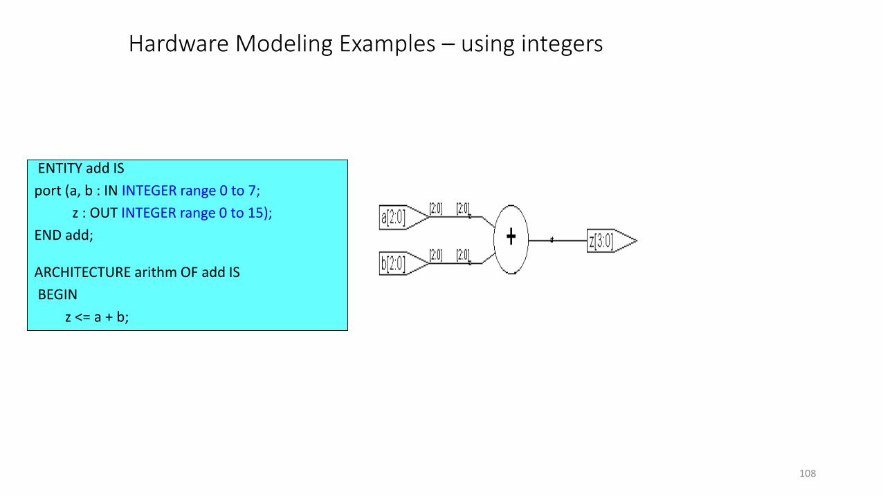
Hardware Modeling Examples – using integers
ENTITY add IS
port (a, b : IN INTEGER range 0 to 7;
z : OUT INTEGER range 0 to 15);
END add;
ARCHITECTURE arithm OF add IS
BEGIN
z <= a + b;
108
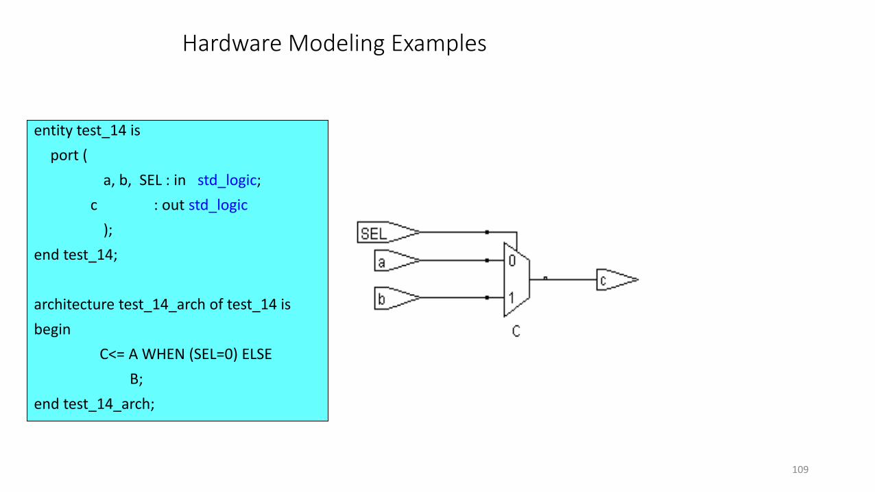
Hardware Modeling Examples
entity test_14 is
port (
a, b, SEL : in std_logic;
c : out std_logic
);
end test_14;
architecture test_14_arch of test_14 is
begin
C<= A WHEN (SEL=0) ELSE
B;
end test_14_arch;
109

Hardware Modeling Examples – using integers
entity test_14 is
port (
a, b, SEL : in integer ;
c : out integer
);
end test_14;
architecture test_14_arch of test_14 is
begin
C<= A WHEN (SEL=0) ELSE
B;
end test_14_arch;
>
>
a [31:0]
b [31:0]
c [31:0]
Sel [0]
Sel [31]
110

Hardware modeling Examples- Latch
Incompletely specified Conditional expression infers a latch.
Latch is a combinational circuit which necessarily has feedback to hold the output to previous value for the unspecified states/conditions.
Avoid the inference of latches in synchronous designs. As latches infer feedback and they cause difficulties in timing analysis and test insertion applications. Most synthesizers provide warnings when latches are inferred.
111
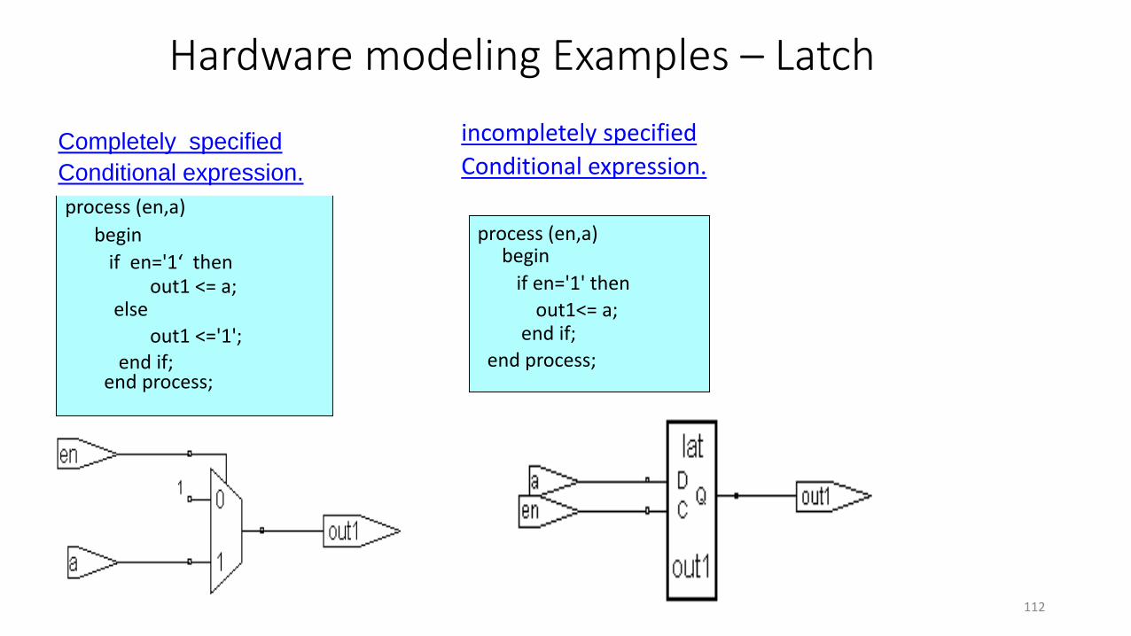
Hardware modeling Examples – Latch
process (en,a)
begin
if en='1‘ thenout1 <= a;
else
out1 <='1';end if;
end process;
process (en,a)begin
if en='1' then
out1<= a;end if;
end process;
Completely specified
Conditional expression.
incompletely specified
Conditional expression.
112
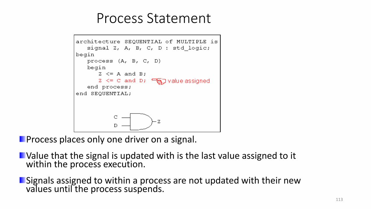
Process Statement
Process places only one driver on a signal.
Value that the signal is updated with is the last value assigned to it within the process execution.
Signals assigned to within a process are not updated with their new values until the process suspends.
113

Wait Statement
Wait statement : Suspends the execution of a process or procedure until some conditions are met.
Three basic forms:
• wait on [sensitivity clause]
• wait until [condition clause]
• wait for [timeout clause]
Wait statement – simulation view.
114

Wait On Clause
“Wait on” statement at the end of the process is equivalent to the “sensitivity list” at the beginning of the process.
A process with a sensitivity clause must not contain an explicit wait statement.
process -- No Sensitivity list begin
if ( clk'event and clk = '1') then q <= d;
end if;wait on clk; -- Replaces the Sensitivity list
end process;
115

Wait Until Clause
process
begin
wait until clk = ‘1’;
q <= d;end process;
‘flip–flop’ inference
process ( clk )
begin
wait until clk = ‘1’;
q <= d;end process;
Illegal coding
Processes with a “wait statement” & “Sensitivity list” are illegal
116

Wait for Clause
process
begin
clock <= ‘0’;
wait for 20ns;
clock <= ‘1’;
wait for 12ns;
end process;
Useful in testbenches for generating waveforms.
117

signal clk : std_logic := '0';
signal cnt1 : std_logic_vector(2 downto 0) := "000";
clk <= not clk after 10 ns;
w1 : process
begin
cnt1 <= cnt1 + '1';
wait for 22 ns;
end process;
signal clk : std_logic := '0';
signal cnt2 : std_logic_vector(2 downto 0) := "000";
clk <= not clk after 10 ns;
w2 : process
begin
wait for 22 ns;
cnt2 <= cnt2 + '1';
end process w2;
Time Cnt1 Cnt2
0 1 0
10 1 0
20 1 0
22 2 1
44 3 2
50 3 2
66 4 3
cnt1 & cnt2 are updated each after 22 ns
118
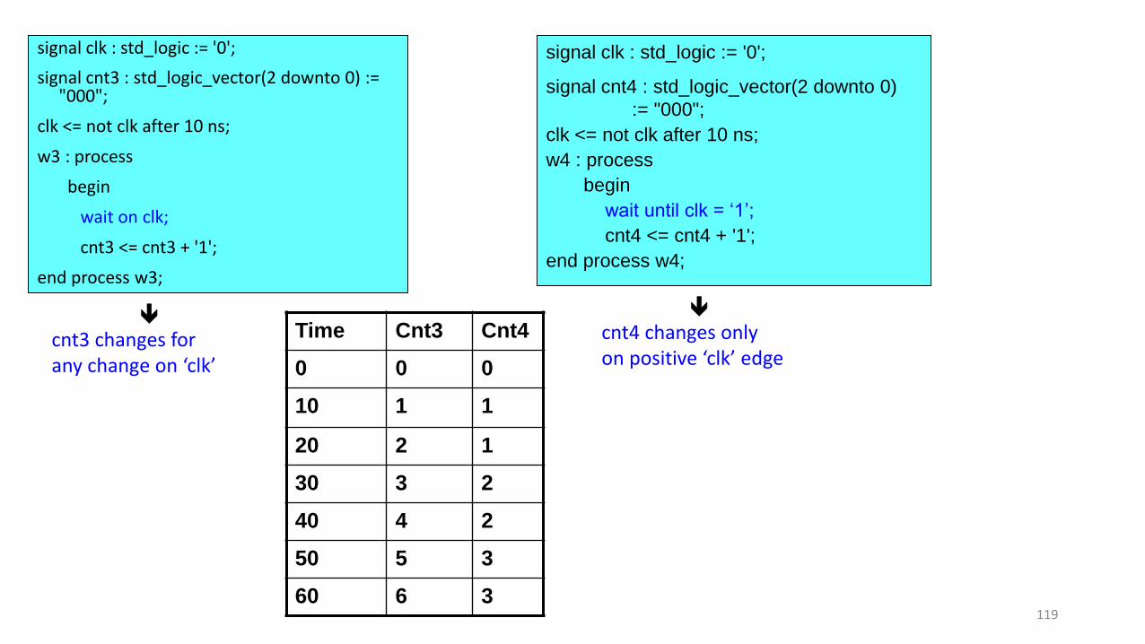
signal clk : std_logic := '0';
signal cnt3 : std_logic_vector(2 downto 0) := "000";
clk <= not clk after 10 ns;
w3 : process
begin
wait on clk;
cnt3 <= cnt3 + '1';
end process w3;
signal clk : std_logic := '0';
signal cnt4 : std_logic_vector(2 downto 0)
:= "000";
clk <= not clk after 10 ns;
w4 : process
begin
wait until clk = ‘1’;
cnt4 <= cnt4 + '1';
end process w4;
cnt3 changes forany change on ‘clk’
cnt4 changes onlyon positive ‘clk’ edge
Time Cnt3 Cnt4
0 0 0
10 1 1
20 2 1
30 3 2
40 4 2
50 5 3
60 6 3119

signal clk : std_logic := '0';
signal cnt5 : std_logic_vector(2 downto 0) := "000";
clk <= not clk after 10 ns;
w5 : process
begin
wait until clk = '1' for 7 ns; cnt5 <= cnt5 + '1';
end process w5;
cnt5 changes whenever positive edge occurs on clk
AND each after 7 ns.
Time Cnt5
0 0
17 1
27 2
37 3
47 4
57 5
67 6
77 7
87 8120

Loop statements – While loop
Loop statements are used to iterate through a set of sequential statements.
Has a Boolean Iteration Scheme.
Condition is evaluated before execution.
Syntax:loop_label: while condition loop
sequence_of_statementsend loop loop_label
121

Loop statements
Loop statements are used to iterate through a set of sequential statements.
Syntax:loop_label: while condition loop
sequence_of_statementsend loop loop_label
process ( Input )
variable i : POSITIVE := 1;
begin
L1: while i <= 8 loop
Output (i) <= Input (i+8) ;
i := i + 1;
end loop L1;
end process;
Has a Boolean Iteration Scheme.
Condition is evaluated before execution.
122

Loop Statements - For Loop
Syntax:loop_label: for loop_parameter in range loop
Sequence_of_statementsend loop loop_label;
Has an Integer Iteration Scheme. Number of repetitions is determined by an Integer range
The loop is executed once for each value in the range
The loop parameter’s range is tested at the beginning of the loop, not at the end.
Example : factorial := 1;
for number in 2 to N loop
factorial := factorial * number;
end loop;
123

For Loop Rules
Loop parameter is implicitly defined.
Inside the loop, the loop parameter is a constant. Thus, it may be used but not altered.
Discrete range of the loop is evaluated before the loop is first executed.
Loop counter only exists within the loop.
Labels in loop parameters enable better loop control with the “next” and “exit” statements.
Labels also enhance readability and maintainability.
124

Loop Statements - For Loop
Shift_5: process (Input_X)
begin
L5: for index in Input_X'range loop
Output_X(index) <= Input_X(7 - index);
end loop L5;
end process;
Bit Reversal
Input_X
7
Output _X
7
Executes the loop for the Specified input range
what will be the hardware ?
125

Loop statements – Next Statement
Syntax:next loop_label when condition;
Skips the remaining statements in the current iteration of the specified loop.
Execution resumes with the first statement in the next iteration of the loop.
for J in 10 downto 5 loop
if sum < total_sum then
sum := sum + 2;
elsif sum = total_sum then
next;
else null;
end if;k : k+1;
end loop;126

Loop statements – exit Statement
Entirely terminates the execution of the loop in which it is located.
Syntax:
exit;
exit loop_label when condition;
sum := 1; j := 0;L3 : loop
J := J + 21;sum := sum * 10;
if sum > 100 then
exit L3;end if;
end loop L3;
Note:
–Exit : Causes the specified loop to be terminated.
–Next :Causes the current loop iteration of the specified loop to be prematurely terminated; execution resumes with the next iteration.
127

Signals and Variables
SIGNALS & VARIABLES – CHARACTERISTICS
SYNTHESIS VIEW
SIMULATION VIEW
128

Signals
Represents wires within a circuit.
Thus Signals can be used• To connect design entities together & communicate changes in values within a design.• Instead of inout signals.
Each signal has a history of values i.e holds a list of values which include current value of signal & set of possible future values that are to appear on the signal.
architecture and_gt of anding is
signal temp : std_logic;
begin
U1 : AND2 portmap (a,b,temp);
U2 : AND2 portmap (temp,a,b);
end and_gt;
129

Variables
These are objects with single current value.
Are used to store the intermediate values between the sequential VHDL
statements.
Variable can be declared & used inside the process statement only. But
retain their value throughout the entire simulation.
process ( a )
variable a_int : integer := 1;
begin
a_int := a_int + 1;
end process;
Note : a_int contains the total number of events that occurred on signal a
130
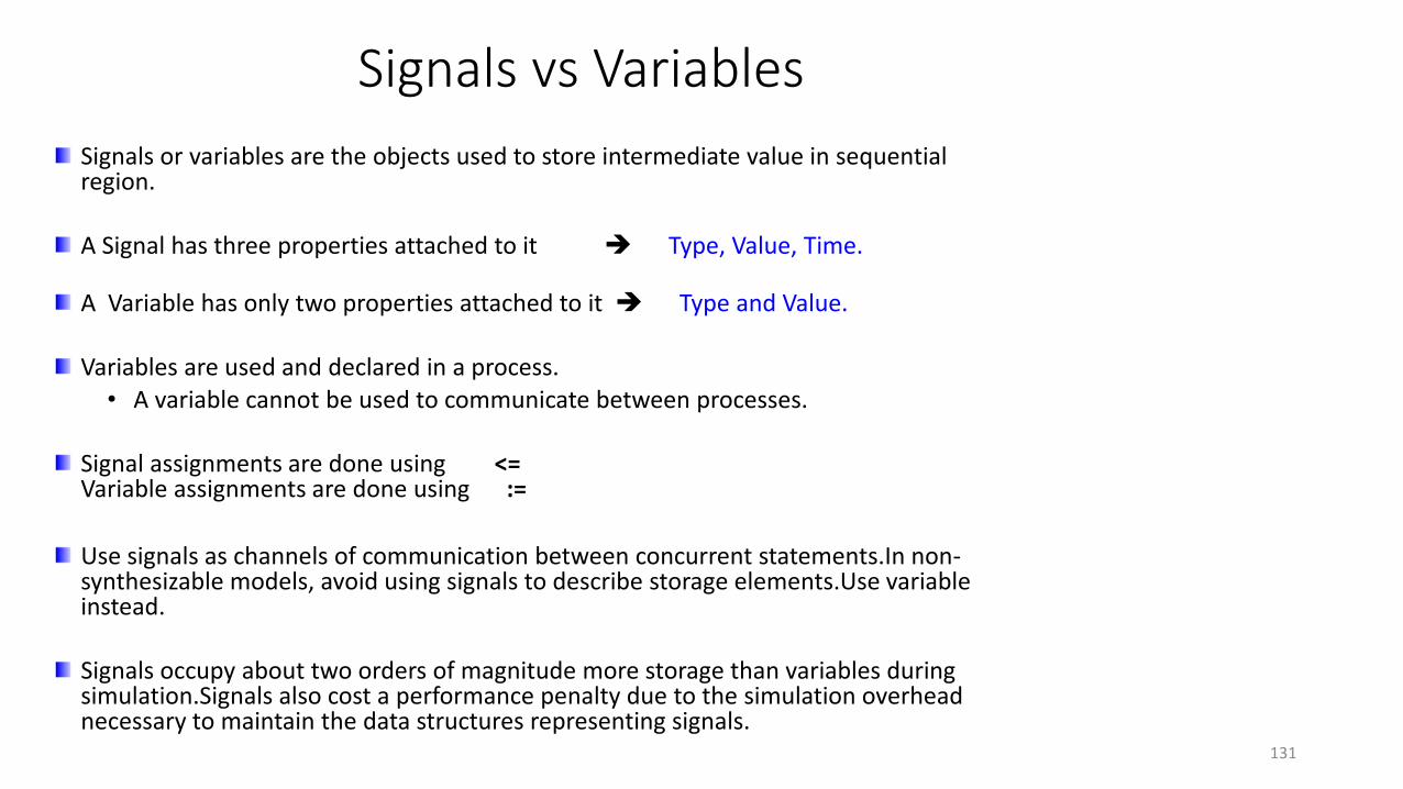
Signals vs Variables
Signals or variables are the objects used to store intermediate value in sequential region.
A Signal has three properties attached to it Type, Value, Time.
A Variable has only two properties attached to it Type and Value.
Variables are used and declared in a process. • A variable cannot be used to communicate between processes.
Signal assignments are done using <= Variable assignments are done using :=
Use signals as channels of communication between concurrent statements.In non-synthesizable models, avoid using signals to describe storage elements.Use variable instead.
Signals occupy about two orders of magnitude more storage than variables during simulation.Signals also cost a performance penalty due to the simulation overhead necessary to maintain the data structures representing signals.
131

Signals and Variables
CASE 1 :
process (clk)
If (clk’event and clk = ‘1’)then
temp := a and b; y <= c and temp;
CASE 2 :
process (clk)
If (clk’event and clk = ‘1’)
then temp <= a and b; y <= c and temp;
132
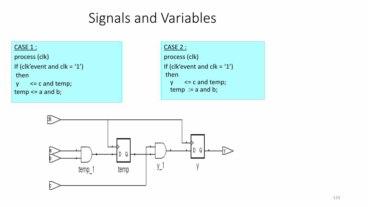
Signals and Variables
CASE 1 :
process (clk)
If (clk’event and clk = ‘1’)
then y <= c and temp;
temp <= a and b;
CASE 2 :
process (clk)
If (clk’event and clk = ‘1’)then
y <= c and temp; temp := a and b;
133

Signals and Variables
process ( clk, a,b,c,d)
variable y, x, w : std_logic;
begin
if clk = '1' and clk'event then
1. z1 <= y; -- y is read before it is written implying memory
2. y := x; -- x is read before it is written implying memory
3. x := a and b;
4. w := c and d;
5. z2 <= w; -- w is written before it is read – needs no memory
end if;
end process;
134

Signals and Variables
Resulting Hardware:
Draw the Hardware for the statement sequence 3, 2,1, 5,4
135

Signals and Variables
Hardware for the statement sequence 3, 2,1, 5,4
136

Signals and Variables
architecture var of parity is
begin
process(a)
variable temp : std_logic;
begin
temp := '0';
for i in 0 to n loop
temp:=temp xor a(i);
end loop;
p<=temp;
end process;
end var;
137

Signals and Variables
architecture sig of par is
signal temp:std_logic;
begin
process (a)
begin
temp <= '0';
for i in 0 to n loop
temp <= temp xor a(i);
end loop;
p<= temp;
end process;
end sig;
138

Signals and Variables
tb : process
begin
wait for 10 ns;
sum1 <= sum1 + 1;
sum2 <= sum1 + 1;
end process;
tb : process
begin
wait for 10 ns;
sum1 := sum1 + 1;
sum2 := sum1 + 1;
end process;
Time Sum1 Sum2
0 0 0
10 0 0
10 + 1 1
20 1 1
20 + 2 2
30 2 2
30 + 3 3
Time Sum1 Sum2
0 0 0
10 1 2
10 + 1 2
20 2 3
20 + 2 3
30 3 4
30 + 3 4 139

Using Signals or Variables
Use Variables in combinatorial processes. ( Less Simulation overhead ).
Order dependency• Signal assignments are order independent. Signals are updated at the end of process.
Signals represent physical wires in the circuit.
• Variable assignments are order dependent, Variables assignments are done immediately and are executed sequentially. Variables may or may not represent physical wires.
Signal assignments under a clocked process are translated into registers.
Variable assignment under a clocked process may or may not be translated into registers.
Computed value is assigned to signal after specified delay called delta delay
Variable assignment occurs immediately.
140

Generics
Are specified in entities inside the generic clause.
Provides information to a block from its environment.• Example : Size of interface ports, width of components
Syntax :generic ( [ constant_name : type [ := value ];
constant_name : type [ := value ] );
141

Generics
entity AND_GATE isgeneric ( N: NATURAL := 3 );port ( A : in std_logic_vector ( 1 to N );
Z : out bit );
architecture gen_ex of and_gate isbegin
process (A)variable and_out : bit;begin
and_out := ‘1’;for K in 1 to N loop
and_out := and_out and A(K);exit when and_out = ‘0’;
end loop;Z <= and_out;
end process;
end gen_ex;142

Generics
Applications of generics• Can be used anywhere in a code where a static value is needed.• Use of generics facilitates easy design changes.• Used in behavioral modeling of components.
• For ex. : Timing parameters such as delays, Set-up times, Hold times can be modeled using Generics.
Generics• Are specified in entities. Hence, any change in the value of a generic affects
all architectures associated with that entity.
Constants• Are specified in architectures. Hence, any change in the value of a constant
will be localized to the selected architecture only.
143

Logic Systems
Need for a multi-valued Logic System
In real life, a digital system may need more values than just '0' and '1' to represent the signal value.
Conventional Logic systems had only three values I.e. ‘0’ , ‘1’ and ‘Z’Consider truth table for AND gate
A B Y0 0 00 1 01 0 01 1 1For 0 Z ???
"Standard Logic" to allow us to represent logic systems with more than just values of '0' and '1'. This is a multi-valued logic system
144

Multivalued Logic System
A 9-value package STD_LOGIC_1164 was developed and accepted as IEEE Std 1164-1993. Possible states of signal are represented using the 9 values are given below
‘U’ : Uninitialized
‘X’ : Unknown
‘0’ : Logic 0
‘1’ : Logic 1
‘Z’ : High impedance
‘W’ : weak unknown
‘L’ : weak logic 0
‘H’ : weak logic 1
‘-’ : Don’t care
U, X, W, - represent behavior of model itself rather than the behavior of hardware being synthesized.
145
Multivalued Logic System
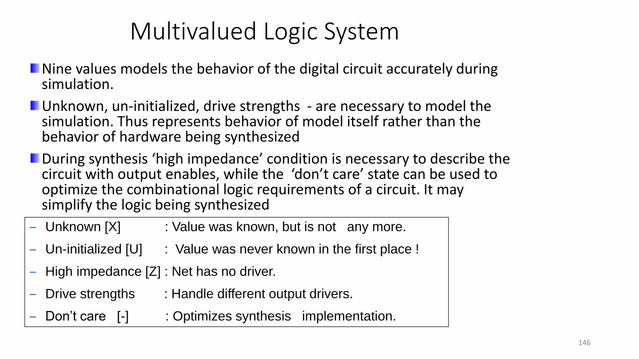
Nine values models the behavior of the digital circuit accurately during simulation.
Unknown, un-initialized, drive strengths - are necessary to model the simulation. Thus represents behavior of model itself rather than the behavior of hardware being synthesized
During synthesis ‘high impedance’ condition is necessary to describe the circuit with output enables, while the ‘don’t care’ state can be used to optimize the combinational logic requirements of a circuit. It may simplify the logic being synthesized
– Unknown [X] : Value was known, but is not any more.
– Un-initialized [U] : Value was never known in the first place !
– High impedance [Z] : Net has no driver.
– Drive strengths : Handle different output drivers.
– Don’t care [-] : Optimizes synthesis implementation.
146

Operator Overloading – Need
Predefined operators are defined only for the operands of certain predefined types.
Example: entity add is
port ( a : in bit;b : in bit;c : out bit );
end add;
architecture correct of add is c <= a + b;
end correct;
147

Operator Overloading
Arithmetic operations are not predefined in the language to work on vectors.
Example:entity add is
port ( a : in std_logic_vector; -------- Error!
b : in std_logic_vector;c : out std_logic_vector );
end add;
architecture wrong of add is
beginc <= a + b;
end wrong;
148
Operator Overloading
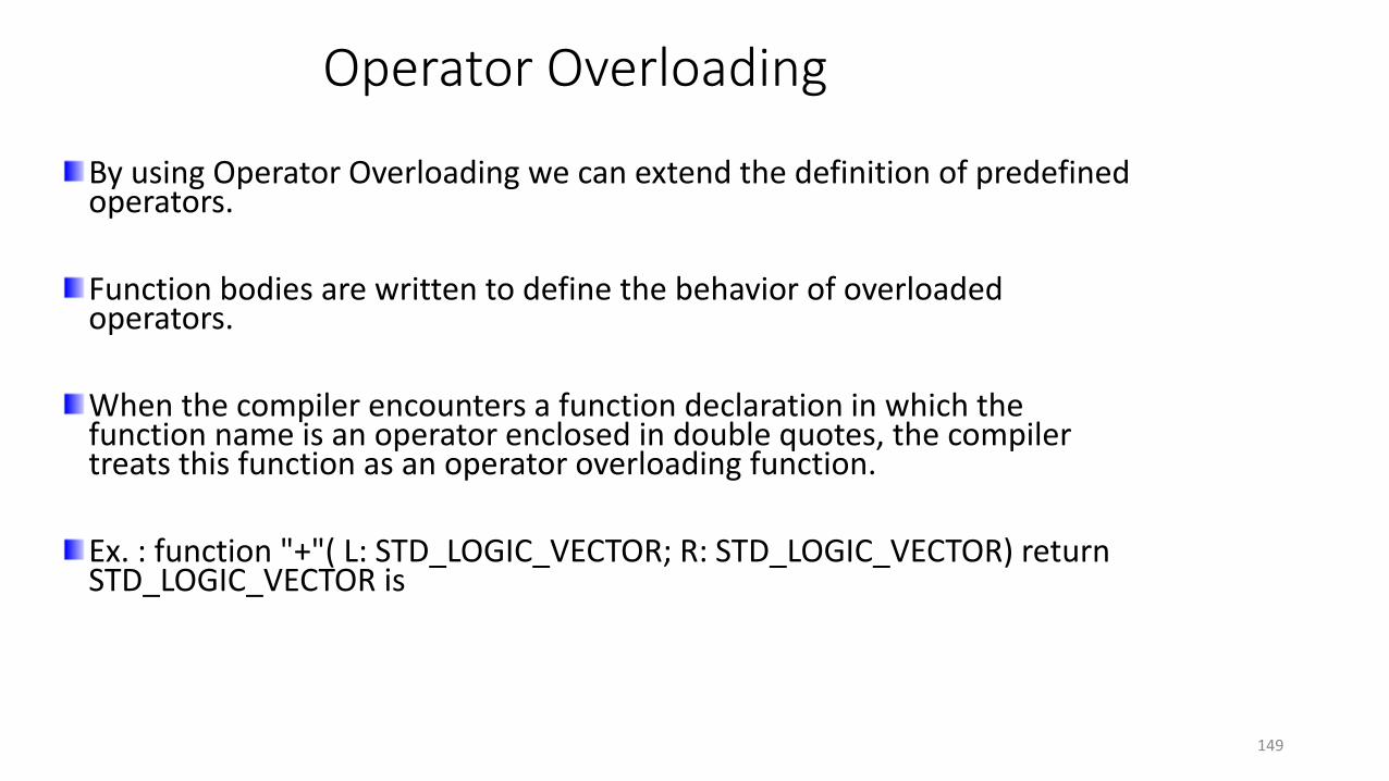
By using Operator Overloading we can extend the definition of predefined operators.
Function bodies are written to define the behavior of overloaded operators.
When the compiler encounters a function declaration in which the function name is an operator enclosed in double quotes, the compiler treats this function as an operator overloading function.
Ex. : function "+"( L: STD_LOGIC_VECTOR; R: STD_LOGIC_VECTOR) return STD_LOGIC_VECTOR is
149
Packages
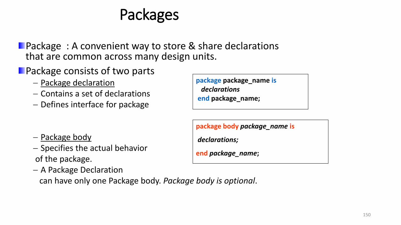
Package : A convenient way to store & share declarations that are common across many design units.
Package consists of two parts Package declaration Contains a set of declarations Defines interface for package
Package body Specifies the actual behaviorof the package. A Package Declaration
can have only one Package body. Package body is optional.
package package_name isdeclarations
end package_name;
package body package_name is
declarations;
end package_name;
150

Packages
USE WORK.DECLARE.ALL;use IEEE.std_logic_1164.all;
entity AND_4BIT isport ( X, Y, Z : in STD_LOGIC;
P :out STD_LOGIC;);end AND_4BIT;
architecture AND_4BIT_arch of AND_4BIT isSIGNAL TEMP1 : STD_LOGIC;
begin
U1 : and_gt PORT MAP (X,Y,TEMP1);U2 : and_gt PORT MAP (Z,TEMP1,P);end AND_4BIT_arch;
Component stored in package named
‘declare’
No Component declaration
151
Packages
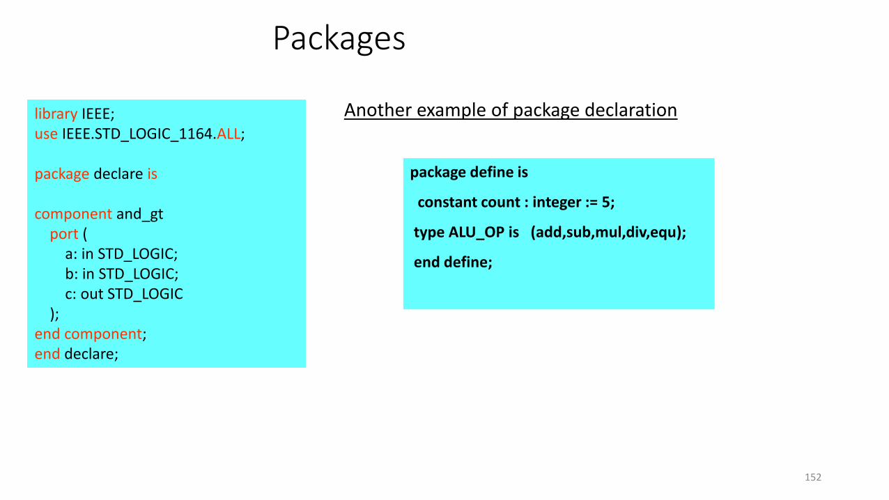
library IEEE;use IEEE.STD_LOGIC_1164.ALL;
package declare is
component and_gtport (
a: in STD_LOGIC;b: in STD_LOGIC;c: out STD_LOGIC
);end component;end declare;
package define is
constant count : integer := 5;
type ALU_OP is (add,sub,mul,div,equ);
end define;
Another example of package declaration
152
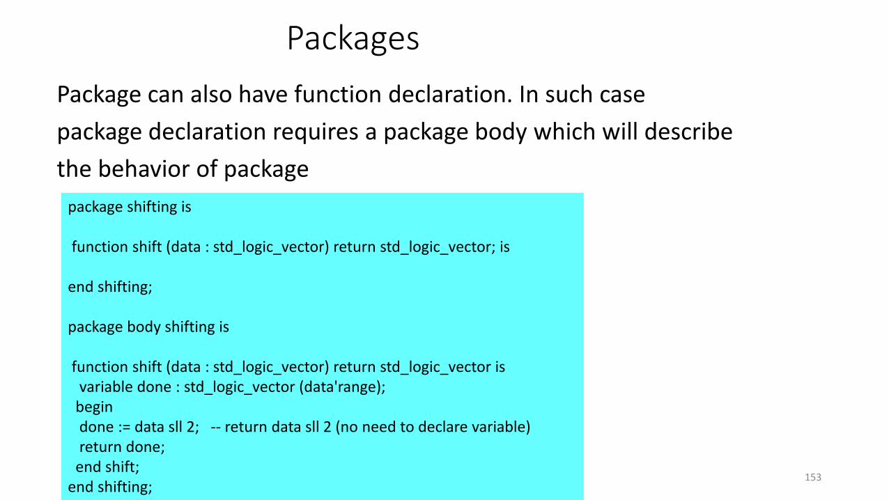
Packages
Package can also have function declaration. In such case
package declaration requires a package body which will describe
the behavior of package
package shifting is
function shift (data : std_logic_vector) return std_logic_vector; is
end shifting;
package body shifting is
function shift (data : std_logic_vector) return std_logic_vector isvariable done : std_logic_vector (data'range);
begindone := data sll 2; -- return data sll 2 (no need to declare variable)return done;
end shift;end shifting;
153

154


