Chapter one: BTU Measurement System .............................................................4
1.1 General introduction...................................................................................................................4
1.2 Working principle & process......................................................................................................4
1.2.1 Working principle...........................................................................................................4
1.2.2 Working process:............................................................................................................4
1.3 BUT meter component description: ...........................................................................................5
Chapter two: C03P BTU Meter ............................................................................6
2.1 General description ..........................................................................................................................6
2.2 Function ...........................................................................................................................................6
AKE BTU Measurement System is used to measure individual energy consumption in any liquid heating/cooling system such as apartment, commercial office, and condominiums. This system is also used to measure performance of energy saving system or the loss of efficiency which is directly tied to loss of revenue. The system real-time detects the temperature of supply and return pipe, monitors the instantaneous flow rate, according to Heat Exchange of thermodynamics principle the BTU meter accumulates each user’s heat energy consumption and transfer the data to up-PC, finally as
per rated unit price (Dollars/MW) to calculate the total fee of them.
1.2 Working principle & process
1.2.1 Working principle
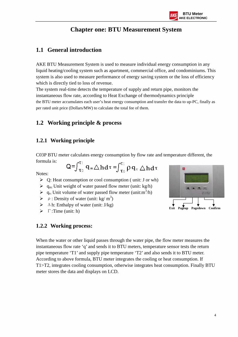
C03P BTU meter calculates energy consumption by flow rate and temperature different, the formula is: Notes: Q: Heat consumption or cool consumption ( unit: J or wh) qm: Unit weight of water passed flow meter (unit: kg/h) qv: Unit volume of water passed flow meter (unit:m3/h) ρ: Density of water (unit: kg/ m3) Δh: Enthalpy of water (unit: J/kg) Γ:Time (unit: h)
1.2.2 Working process:
When the water or other liquid passes through the water pipe, the flow meter measures the instantaneous flow rate ‘q’ and sends it to BTU meters, temperature sensor tests the return pipe temperature ‘T1’ and supply pipe temperature ‘T2’ and also sends it to BTU meter. According to above formula, BTU meter integrates the cooling or heat consumption. If T1>T2, integrates cooling consumption, otherwise integrates heat consumption. Finally BTU meter stores the data and displays on LCD.
Exit Pageup Pagedown Confirm
5
BTU Meter AKE ELECTRONIC
1.3 BUT meter component description:
6
BTU Meter AKE ELECTRONIC
Chapter two: C03P BTU Meter
2.1 General description
C03P BTU Meter is a liquid heat exchange calculation device for Central Air-conditioning. Besides heating calculation, it also could calculate cooling energy consumption. It collects the data from temperature sensor and flow meter, basing on Heat Exchange principle the system automatically integrates energy consumption and transfers it to PC. It can check consumption volume by tenant or operator, real time shows instantaneous temperature, flow rate and energy consumption etc., it also has the ability to show history data with bar chart.
1. BTU meter(Model: C03P)—Calculates the energy consumption with high accurate and
reliable, mounted on the wall, no condensated water problems; 2. Temperature Sensors—PT1000 3. Flow meter: Electromagnetic Flow meter, Vortex Flow meter, Rotameter are available,
recommends Electromagnetic Flow meter
2.2 Function
Calculates heating and cooling energy consumption; Tracks accumulated energy consumption; Tracks historical data with graphic analysis; Has remotely warn function; Real-time monitor function; Storage security of data, stores data automatically once power failure; Has real-time clock function;
2.3 Characteristic:
Large LCD screen, real time shows supply/return water temperature, instantaneous flow rate, cooling consumption value, heating consumption value, instantaneous power, total flow rate etc.;
Shows history data with bar chart, easily analyze and check; All the designed parameter is much more closed to actual project application,
multi-password protected prevents data missed and revised; Perfect interface design, Current input (4-20mA) and pulse input compatible, suitable
for different kinds of flow meters to collect signal; RS485 or M-Bus Communication interface, reliable; Electricity and optics is isolated, good anti-interference performance; Remote warn and clock function, remotely revise the time periodically; Has data output interface, could be integrated into Auto Reading Meter system; Can be auto setup small flow rate ignored;
7
BTU Meter AKE ELECTRONIC
2.4 Parameter
2.5 Operation instruction
2.5.1 Keypad operation meaning
:Exit;
:Page up or upwards;
:Page down or downwards;
:Confirm or select;
Operating voltage 220VAC±10% ,50±1Hz Temperature range (0.0~99.9) Temperature accuracy ±0.1 Matched with temperature sensor PT1000 Flow rate range (0~9999.99)m3/h Flow rate accuracy ±1.5% Matched with flow rate sensor Pulse mode or Current mode
Flow rate signal range Pulse mode:0~200Hz Current mode:4-20mA
Cooling consumption accumulated range (0~999999.999999)MWh Heating consumption accumulated range (0~999999.999999)MWh Resolution ratio 0.000001MWh Energy accumulated accuracy ClassⅡ Communication interface RS-485 Communication rate 9600bps Max. communication distance 400m Dimension 250mm×150mm×60mm
8
BTU Meter AKE ELECTRONIC
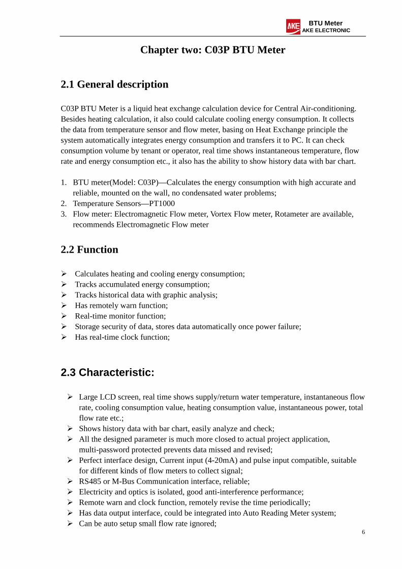
2.5.2 Menu operation
Menu
Usual
Data
Energy
Flow Rate
Time
Water
Temp.
Tot. Cool: Mwh
Tot. Heat: Mwh
Water Return T1:
Water Supply T2:
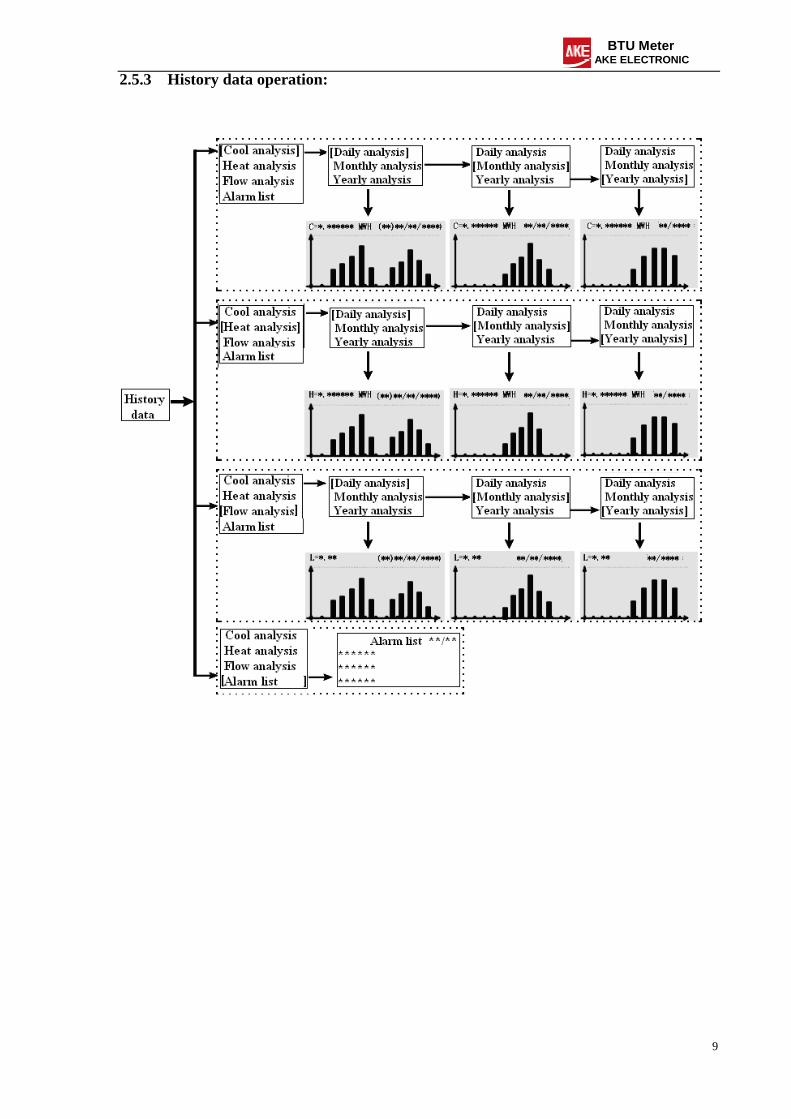
Hist. Data
Other info
Para. set
Tot.FlowRate: m3
Inst. FlowRate: m3/h
Inst. Flux speed: m/s
Inst. Power: kj/s
Total Cooling 01/02
Today: MWh
Month: MWh
Total: MWh
Flow rate
Current: m3/h
Today: m3
Month: m3
Water return T1 :
Water supply T2 :
Temp. diff. :
Max temp. diff. :
Date:
Time:
Tot. Run time:
Tot. Alarm time:
[Cool analysis] Heat analysis Flow rate analysis Alarm list
Parameter setting User setting Project setting Factory setting
User setting 1/12 T1 alarm upper limit: 80.0 Return Enter
T1 alarm upper limit 80.0
Return Enter
User setting 2/12 T1 alarm lower limit: 02.0 Return Enter
T1 alarm lower limit 02.0
Return Enter
User setting 3/12 T2 alarm upper limit: 80.0 Return Enter
T2 alarm upper limit 80.0
Return Enter
User setting 4/12 T2 alarm lower limit: 02.0 Return Enter
T2 alarm lower limit 02.0
Return Enter
User setting 5/12 T1 upper limit 80.0 Return Enter
T1 upper limit 80.0
Return Enter
User setting 6/12 T1 lower limit: 02.0 Return Enter
T1 lower limit 02.0
Return Enter
User setting 7/12 T2 upper limit 80.0 Return Enter
T2 upper limit 80.0
Return Enter
User setting 8/12 T2 lower limit: 02.0 Return Enter
T2 lower limit 02.0
Return Enter
User setting 9/12 Alarm time reset Return Enter
Please input password 0*****
Return Enter
User setting 10/12 History data reset Return Enter
Please input password 0*****
Return Enter
User setting 11/12 Meter mode: Cool & Heat Return Enter
Meter mode Cool&Heat Cool Heat Return Enter
User setting 12/12 Password reset Return Enter
11
BTU Meter AKE ELECTRONIC
2.5.5 Parameter set – Project setting
Please input password 0*****
Return Enter
Project setting 1/12 Flowmeter type Return Enter
Flowmeter type Electrical Pulse
Return Enter
Project setting 2/12 Coefficient of flow (P) Return Enter
Coefficient of flow (P) 01.0000P/L
Return Enter
Project setting 3/12 Pipe diameter set (E) Return Enter
Pipe diameter set (E) 050mm
Return Enter
Project setting 4/12 Max flow speed set (E) Return Enter
Max flow speed set (E) 4.0 m/s
Return Enter
Project setting 5/12 Low flow ignored (E) Return Enter
Low flow ignored (E) 0.0(0.0)m/s
Return Enter
Project setting 6/12 Min temp. different (C) Return Enter
Min temp. different (C) 0.2
Return Enter
Project setting 7/12 Min temp. different (H) Return Enter
Min temp. different (H) 5.0
Return Enter
Project setting 8/12 Sampling interval Return Enter
Sampling interval 05s
Return Enter
Project setting 9/12 T1 zero compensation Return Enter
T1 zero compensation +0.0
Return Enter
Project setting 10/12 T2 zero compensation Return Enter
T2 zero compensation +0.0
Return Enter
Project setting 11/12 Meter address Return Enter
Meter address 00
Return Enter
Project setting 12/12 Password modifying Return Enter
12
BTU Meter AKE ELECTRONIC
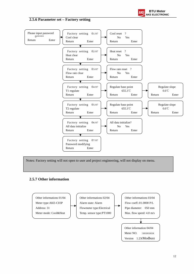
2.5.6 Parameter set – Factory setting
2.5.7 Other information
Please input password 0*****
Return Enter
Factory setting 01/07 Cool clear Return Enter
Cool reset ? No Yes
Return Enter
Factory setting 02/07 Heat clear Return Enter
Heat reset ? No Yes
Return Enter
Factory setting 03/07 Flow rate clear Return Enter
Flow rate reset ? No Yes
Return Enter
Factory setting 04/07 T1 regulate Return Enter
Regulate base point 655.3
Return Enter
Factory setting 05/07 T2 regulate Return Enter
Regulate slope 0.0
Return Enter
Factory setting 06/07 All data initialize Return Enter
All data initialize? No Yes
Return Enter
Factory setting 07/07 Password modifying Return Enter
Regulate base point 655.3
Return Enter
Regulate slope 0.0
Return Enter
Other informations 01/04
Meter type:AKE-C03P
Address: 31
Meter mode: Cool&Heat
Other informations 02/04
Alarm state: Alarm
Flowmeter type:Electrical
Temp. sensor type:PT1000
Other informations 03/04
Flow coeff.:01.0000 P/L
Pipe diameter: 050 mm
Max. flow speed: 4.0 m/s
Other information 04/04
Meter NO. :xxxxxxxx
Version 1.23(Modbus)
Notes: Factory setting will not open to user and project engineering, will not display on menu.
13
BTU Meter AKE ELECTRONIC
2.6 Installation and adjustment
2.6.1 Installation Notes
Must cut off power when installing or operating, otherwise will damage component; Selects a correct installation locations; Environment temperature:-30 - +70; Relative humidity: Max relative humidity 95% (Non-condensing); RS485 communication, strictly adopts RVS2*0.75mm2 twisted-pair; Connects the wires according the label indication; Before power ON, please check the wires again to avoid wrong connection which will
damage the component; check the wires again to avoid wrong connection which will damage the component;
2.6.2 Installation wiring schematic drawing
14
BTU Meter AKE ELECTRONIC
2.6.3 Connection instruction:
In the end of C03P BTU Meter it has a 24bit standard connecting terminal, it is used for connecting signal and power supply;
The connection method between C03P BTU Meter and temperature sensor PT1000 is four-wire system;
The connection method between C03P BTU Meter and flow meter should be accordance with flow meter mode;
If match with pulse mode flow rate, the terminal no. 5 should connect with flow meter DC power supply input point, terminal no.4 should connect with flow meter signal ground point, terminal no. 6 should connect with flow meter pulse signal output point;
The power supply connection method is that connect terminal no. 1 and 3 with AC 200V null line and live wire, terminal no.2 connect with GND;
2.6.4 BTU Meter installation procedure:
Puts BTU Meter into the iron box we offered before installing; Drills holes as per BTU Meter dimension by churn drill and then screwed; Connects iron box and temperature sensor and flow meter; Connects the wire as per label indication;
2.7 Equipment enlarge figure
Drawing: BTU Meter electrical cabinet enlarge figure
15
BTU Meter AKE ELECTRONIC
Drawing: BTU Meter enlarge figure
16
BTU Meter AKE ELECTRONIC
Drawing: Installation gasket enlarge figure
17
BTU Meter AKE ELECTRONIC
2.8 Environment requirement and connection technology
Installation: 1) BTU Meter should be installed at waterproof environment; 2) Environment humidity can’t over 95%, temperature 0-50; 3) Forbid installing at air-conditioning water shaft or oil dirt environment. Connection:1) Please strictly connect the wires as per indication, otherwise will damage the
component; 2) When connecting with other devices, please note the connection indication; 3) It is better to use cold compression plug while connecting;
2.9 Fault analysis and elimination
Problem 1: Hasn’t flow rate display Solution: 1) Checks flow meter connection wires to judge whether have 24V output. For insert electromagnetic flow meter, if have, the power supply is normal. But for ducted electromagnetic flow meter, the power supply is directly offered by separately 220V, BTU Meter will not offer power to it, 2) Checks the low flow rate ignored parameter, normally it should be between 0.01-0.03. If the value is over and bigger than that range, it means the system have stream when set up this parameter, must be set under stagnant water situation. Problem 2: The temperature of water delivery or water return is 2 or 80 Solution: Please check the connection wires between BTU Meter and temperature sensor. Problem 3: Can’t communicate Solution: 1) Please check the power supply AC 220V is normal or not, check fuse which inside the Meter is ok or not; 2) Please check communication positive pole and negative pole is correct or not; 3) Please cut off power supply and then connect again, checks if the fault is eliminated or not; 4) Please check whether the IP add is reduplicate in a same group; Problem 4: when matching with electromagnetic flow meter, it has flow rate but no current actually Solution: Checks the low flow rate ignored parameter, the zero point of electromagnetic flow meter will shift with long time used, please re-set up this parameter. Problem 5: No display on BTU Meter or display Unicode Solution: Please cut offer power supply and then connect again, if still exist that’s means the BTU Meter is broken and need maintain.
18
BTU Meter AKE ELECTRONIC
Chapter three: Electromagnetic flow meter
3.1 Ducted Electromagnetic Flow meter
3.1.1General introduction
Electromagnetic flow meter(EMF) consists of converter and sensor, all of AKE EMF is split designed, the converter and sensor is connected by a signal cables.
Drawing 3-1
3.1.2 Technical parameter
Converter technical parameter
Precious class 0.5% Output single
Current output:4-20mA Frequency output:
Active pulse: High level≥11V,Low level ≤0.5V, Load current≤20mA; Passive pulse: High level= External power-1V(external power should
Electropode material: FEP、NE、P0、PTFE selectable Medium temperature: -40-180 (decided by inner material) Shell material: Carbon steel Protect degrade: IP65,IP67,IP68
Dimension
20
BTU Meter AKE ELECTRONIC
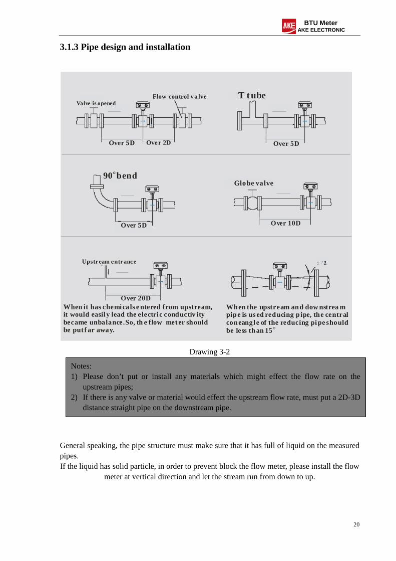
3.1.3 Pipe design and installation
Valve is openedFlow control va lve
Over 5D Over 2D
T tube
Over 5D
Over 5D Over 10D
Over 20D
90 bend。Globe valve
Upstream entrance
When it has chemicals e ntered from upstream,it would easil y lead the electri c conductiv ity became unbalance.So, th e flow meter shouldbe put f ar away.
When the upstream and dow nstrea m pipe is used reducing p ipe, the central coneangle of the reducing pipe shouldbe less than 15。
Drawing 3-2
General speaking, the pipe structure must make sure that it has full of liquid on the measured pipes. If the liquid has solid particle, in order to prevent block the flow meter, please install the flow
meter at vertical direction and let the stream run from down to up.
Notes: 1) Please don’t put or install any materials which might effect the flow rate on the
upstream pipes; 2) If there is any valve or material would effect the upstream flow rate, must put a 2D-3D
distance straight pipe on the downstream pipe.
21
BTU Meter AKE ELECTRONIC
Horizontal pipe
Installed at higher pipe
Open-put pipe or exhaust pipe
Verti cal pipe
Installed at lower pipe
Drawing 3-3
Must make sure that there isn’t any bubble on the measurement position:
Right positionWrong posit ion
Must install a globe valve on the highest downst re am
Wrong position
Drawing 3-4
3.1.4 Connected with earth
Because the electromagnetic flow meter inductive signal is very weak and it is easily effected by noise, the related sensor and converter GND should be same as measured liquid, that means they must connect with earth. The Connecting Earth Ring on the shell of electromagnetic flow meter are used for connecting with earth and keep the same potential as measured liquid. i) Pipe material: common metal pipes
Remark: If the pipe do well in earth connected, could ignore this step, but the Connecting Earth Ring on the shell of the electromagnetic flow meter must connect with pipe. ii) Pipe material: insolated pipes (plastic pipes, rubber pipes)
22
BTU Meter AKE ELECTRONIC
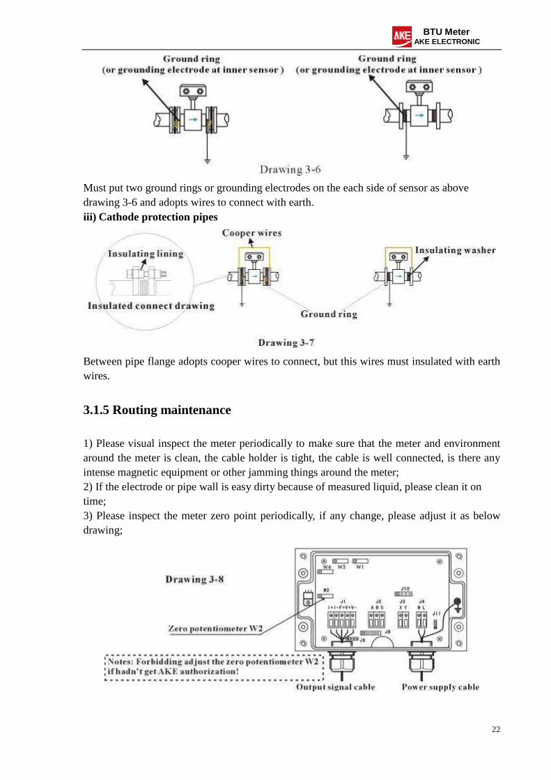
Must put two ground rings or grounding electrodes on the each side of sensor as above drawing 3-6 and adopts wires to connect with earth. iii) Cathode protection pipes
Between pipe flange adopts cooper wires to connect, but this wires must insulated with earth wires.
3.1.5 Routing maintenance
1) Please visual inspect the meter periodically to make sure that the meter and environment around the meter is clean, the cable holder is tight, the cable is well connected, is there any intense magnetic equipment or other jamming things around the meter; 2) If the electrode or pipe wall is easy dirty because of measured liquid, please clean it on time; 3) Please inspect the meter zero point periodically, if any change, please adjust it as below drawing;
23
BTU Meter AKE ELECTRONIC
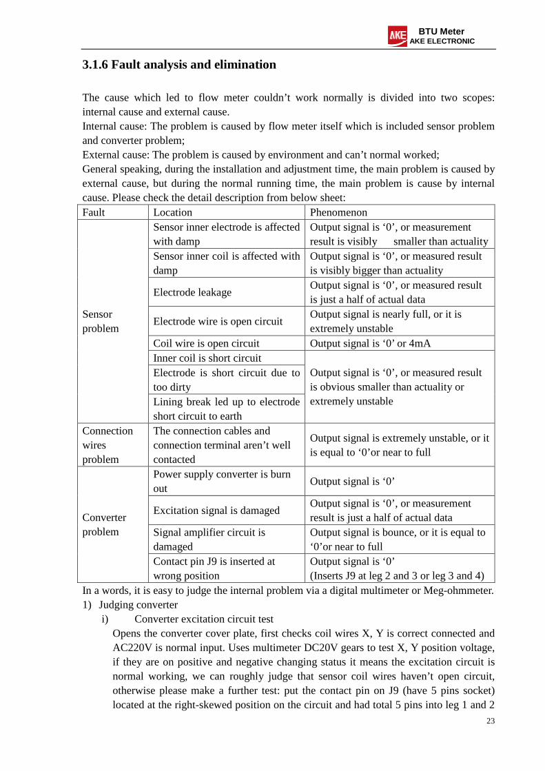
3.1.6 Fault analysis and elimination
The cause which led to flow meter couldn’t work normally is divided into two scopes: internal cause and external cause. Internal cause: The problem is caused by flow meter itself which is included sensor problem and converter problem; External cause: The problem is caused by environment and can’t normal worked; General speaking, during the installation and adjustment time, the main problem is caused by external cause, but during the normal running time, the main problem is cause by internal cause. Please check the detail description from below sheet: Fault Location Phenomenon
Sensor inner electrode is affected with damp
Output signal is ‘0’, or measurement result is visibly smaller than actuality
Sensor inner coil is affected with damp
Output signal is ‘0’, or measured result is visibly bigger than actuality
Electrode leakage Output signal is ‘0’, or measured result is just a half of actual data
Electrode wire is open circuit Output signal is nearly full, or it is extremely unstable
Coil wire is open circuit Output signal is ‘0’ or 4mA Inner coil is short circuit Electrode is short circuit due to too dirty
Sensor problem
Lining break led up to electrode short circuit to earth
Output signal is ‘0’, or measured result is obvious smaller than actuality or extremely unstable
Connection wires problem
The connection cables and connection terminal aren’t well contacted
Output signal is extremely unstable, or it is equal to ‘0’or near to full
Power supply converter is burn out
Output signal is ‘0’
Excitation signal is damaged Output signal is ‘0’, or measurement result is just a half of actual data
Signal amplifier circuit is damaged
Output signal is bounce, or it is equal to ‘0’or near to full
Converter problem
Contact pin J9 is inserted at wrong position
Output signal is ‘0’ (Inserts J9 at leg 2 and 3 or leg 3 and 4)
In a words, it is easy to judge the internal problem via a digital multimeter or Meg-ohmmeter. 1) Judging converter
i) Converter excitation circuit test Opens the converter cover plate, first checks coil wires X, Y is correct connected and
AC220V is normal input. Uses multimeter DC20V gears to test X, Y position voltage, if they are on positive and negative changing status it means the excitation circuit is normal working, we can roughly judge that sensor coil wires haven’t open circuit, otherwise please make a further test: put the contact pin on J9 (have 5 pins socket) located at the right-skewed position on the circuit and had total 5 pins into leg 1 and 2
24
BTU Meter AKE ELECTRONIC
located at left side of J9, at this time the voltage value should be between 10V to 25V, and then put the contact pin into leg 4 and 5 located at the right side of J9, the voltage value should be same as leg 1 and 2 but has different pole. Please remember while finish all testing, the contact pin must be put back leg 2 and 3 or leg 3 and 4 again.
ii) Converter signal amplifier circuit test Pulls out electrode A and B from socket and lets it empty, tests sensor output current
via mutimeter 200mA gears, the data should be beat up and down or exceed 20mA; directly connects A and B with a cable to make it short circuit, the output current should be back to zero, otherwise we can judge that the signal amplifier circuit have some problem.
2) Judging sensor First, cuts off power supply; Make sure that the measured pipes are full of liquid, tests sensor parameters, such as electrode earth resistance, coil resistance, coil insulated earth resistance, when finish all the testing, we can rough judge whether sensor has problem or not. Please follow process as below: i) Opens connection wires between sensor and converter (terminal A, B, C, X, Y); ii) Tests the resistance between A, C and B, C via digital mutimeter, the value should be
similar otherwise maybe one electrode is leakage or affected with damp, or one electrode is too dirty; If the value is under 5000Ω or near to zero, it means the electrode is leakage or affected with damp; if the value is infinite, it means the cable is open circuit;
iii) Checks excitation coil Measures the resistance between X and Y, If the value is over 200Ω, it means excitation coil is short circuit, maybe because the coil or connection cables is short circuit; But if this problem will lead output signal smaller than actual data or near to zero, please contact our company; Measures insulated resistance between coil output cable and C, it should be over 200MΩ. The coil is easy to effect with damp which will lead to flow meter’s zero point and output signal higher than normal. When the insulated resistance between 50MΩ to 200MΩ, maybe the problem is the measured pipe shell is effected with damp, can be dried by air heater; But after dried, if the value is still under 50MΩ, maybe the problem is sensor effected with damp serious, should be repaired.
Flow meter fault and phenomenon (external cause)
Fault Location Phenomenon AC220V cuts off The sensor connection point X, Y are wrong connected Output signal cable is open circuit
Output signal is ‘0’
Current output signal cable is short circuit
Secondary display is ‘0’, or smaller than actuality
The sensor connection point A, B, C are wrong connected
Output signal is ‘0’, or bigger than actuality, or extremely unstable
Connected problem
Connection point X and Y or A and B Output signal is ‘0’. For 4-20mA
25
BTU Meter AKE ELECTRONIC
are connected conversely Sensor position is connected conversely
flow meter, the output signal is 4mA, while flow is opened but the current signal is decrease.
It has vapor-liquid two phase scene on measured pipe There is some abnormal material from upstream entered into flow meter which effects conductivity unstably
Output signal is extremely unstable, big error
The straight pipe length on upstream is not enough It has convex place on the upstream pipe or gasket is not well installed
Installed problem
The measured pipe is vibrant seriously
Output signal is extremely unstable, big error
Actual flow rate is bigger than the flow meter upper limit
Output signal is near to full, but the signal is normal while flow rate is decrease
Model selection problem
Flow meter output signal type isn’t match with secondary meter
Secondary index is ‘0’, or actual data has big difference
Actual flow rate has big difference as user estimated
Wrong judgement
The measured pipe has sub-branch or sub-branch wasn’t considered when estimated.
The display data is different as actual data
Flow meter output signal cables are put at the same or parallel cable duct with power cable Electromagnetic
interference There is big motor, inverter or other strong electromagnetic equipment around the measured location
Output signal is extremely unstable, and big difference
The measured liquid has solid material by itself
Output signal is extremely unstable and big difference, should choose a flow meter suitable for serosity
Measured liquid problem
Measured liquid conductivity < 10us/cm
Output signal is extremely unstable, big difference
GND problem Measured liquid and flow meter shell is both connected earth
Output signal is ‘0’, drift slowly, or extremely unstable
26
BTU Meter AKE ELECTRONIC
3.2 DWM2000 inserted flow meter
3.2.1 General introduction
DWM2000 serial electromagnetic flow meter is used for measuring the flow rate for conducting medium, the output signal is 4-20mA. Parameter characteristic: Internal protection: IP66; Immersion part material is stainless steel and
ceramic; Working temperature: below 150; Working pressure: 25bar or 360psig; No mechanical moving part, free of
maintenance; The electronic parts could be directly
changed while working; Low power consumption; Suitable pipe: ≧50mm or ≧ 2”
3.2.2 Measuring principle
While conductor is moving in the magnetic field, the moving parts will generate voltage. In this system the liquid acts as conductor, magnetic direction B is vertical with flow direction, the generated voltage U will have linear relationship with flow rate V. U=K*B*V*D K: meter coefficient B: magnetic intensity V: liquid flow rate D: electrode gap
Drawing: 3-10
27
BTU Meter AKE ELECTRONIC
3.2.3 Combined equipment
(1) Connect cover (2) Seal ring (3) Sensor (4) Connection thread (5) Grounding cable\ (6) GND terminal (7) Cable input PG13.5 (8) Shell (9) Empty socket (10) Power supply connection (11) Junction box (12) Electromagnetic coil and electrode
connection point (13) Electronic amplifier (14) Screw thread on shell (15) Shell with seal ring
Drawing 3-11
3.2.4 Installation & Connection
(1) All the solder should be operated while no water in the pipe; (2) Installs the connection cover on the pipe line; (pipe diameter ≧50”); (3) Regarding the installation location and inserted depth, please check Drawing 3-17; (4) Straight section of inlet and outlet: 10*DN/5*DN; (DN: pipe diameter) (5) Chooses a suitable location to install flow meter on water return pipe and drills a hole
(diameter: 39mm); (If there is no suitable place on return pipe, supply pipe is also ok) (6) Must use stainless steel electrode (¢2.5 or ¢3.2 ); (7) Calculates the inserted depth, please notes that the scale should be aligned with pipe inner
diameter but not the external diameter. (8) Put the cover in the hole and align with pipe inner diameter as per scale, solders and
makes it vertical on the pipe. The solder should be smooth and well soldered.
Drawing 3-13
(9) It is better to use wet cotton fabric to protect the hole avoid some welding slag dropped on the screw and destroyed.
28
BTU Meter AKE ELECTRONIC
(10) After solder the cover, please use a test unit to screw it into cover, it is better to dip some butter on the screw as a lube to protect the screw, because the screw might be distorted due to high temperature when soldering. Must try screw first, otherwise it might damage the flow meter screw and then damage the flow meter. If the test unit could be smoothly screwed, we can install flow meter, otherwise, forbidden!
(11) Before installing flow meter, please make sure that there is no any welding slag around the pipe, gasket and screw, must make it very clear, otherwise would lead to leakaged;
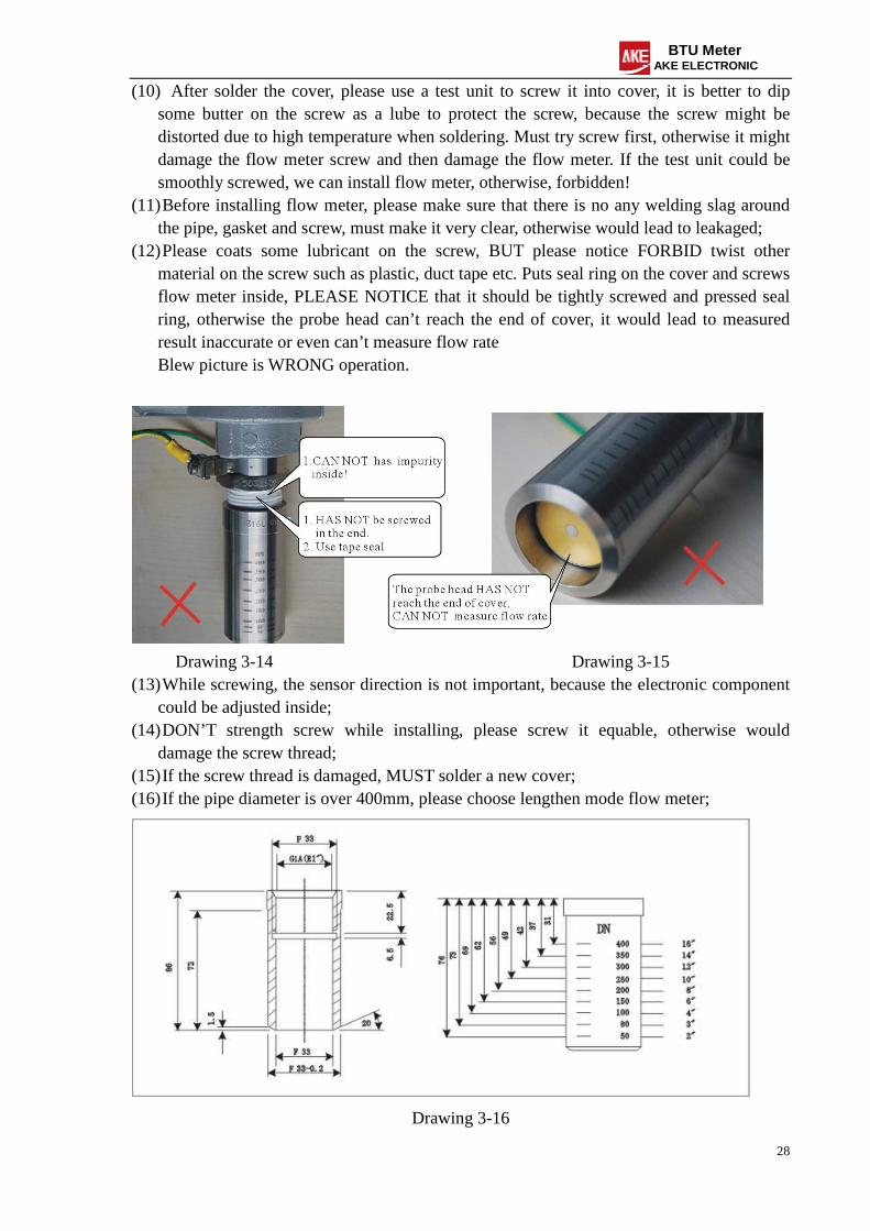
(12) Please coats some lubricant on the screw, BUT please notice FORBID twist other material on the screw such as plastic, duct tape etc. Puts seal ring on the cover and screws flow meter inside, PLEASE NOTICE that it should be tightly screwed and pressed seal ring, otherwise the probe head can’t reach the end of cover, it would lead to measured result inaccurate or even can’t measure flow rate Blew picture is WRONG operation.
Drawing 3-14 Drawing 3-15 (13) While screwing, the sensor direction is not important, because the electronic component
could be adjusted inside; (14) DON’T strength screw while installing, please screw it equable, otherwise would
damage the screw thread; (15) If the screw thread is damaged, MUST solder a new cover; (16) If the pipe diameter is over 400mm, please choose lengthen mode flow meter;
Drawing 3-16
29
BTU Meter AKE ELECTRONIC
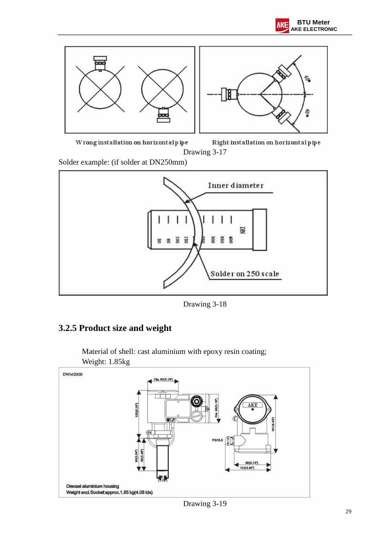
Drawing 3-17
Solder example: (if solder at DN250mm)
Drawing 3-18
3.2.5 Product size and weight
Material of shell: cast aluminium with epoxy resin coating; Weight: 1.85kg
Drawing 3-19
30
BTU Meter AKE ELECTRONIC
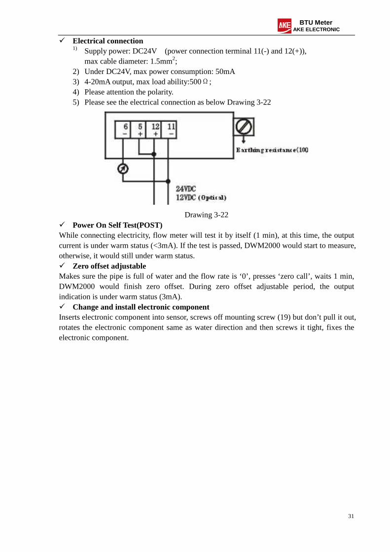
3.2.6 Electrical connection and setup
Please see the PCB circuit as below drawing 3-20: Setup: Must follow processes as below description; Electronic component adjustment; Setup full scale range; Zero offset adjustment;
Drawing 3-20 Setup direction Opens shell, screws off the mounting screws (just rotate two circles, no need pull it out), adjusts electronic components to let the direction same as flow direction, finally screws the mounting screws again. If the direction isn’t same as water direction, the measured result would be wrong; Setup full scale range Before connecting electricity, must setup full scale range first. It could be adjusted between 1-8m/s, if it is wrong set, the device would be in warm status. According to air-conditioning normal flow rate, it could be set as 3m/s.
2) Under DC24V, max power consumption: 50mA 3) 4-20mA output, max load ability:500Ω; 4) Please attention the polarity. 5) Please see the electrical connection as below Drawing 3-22
Drawing 3-22 Power On Self Test(POST) While connecting electricity, flow meter will test it by itself (1 min), at this time, the output current is under warm status (<3mA). If the test is passed, DWM2000 would start to measure, otherwise, it would still under warm status. Zero offset adjustable Makes sure the pipe is full of water and the flow rate is ‘0’, presses ‘zero call’, waits 1 min, DWM2000 would finish zero offset. During zero offset adjustable period, the output indication is under warm status (3mA). Change and install electronic component Inserts electronic component into sensor, screws off mounting screw (19) but don’t pull it out, rotates the electronic component same as water direction and then screws it tight, fixes the electronic component.
32
BTU Meter AKE ELECTRONIC
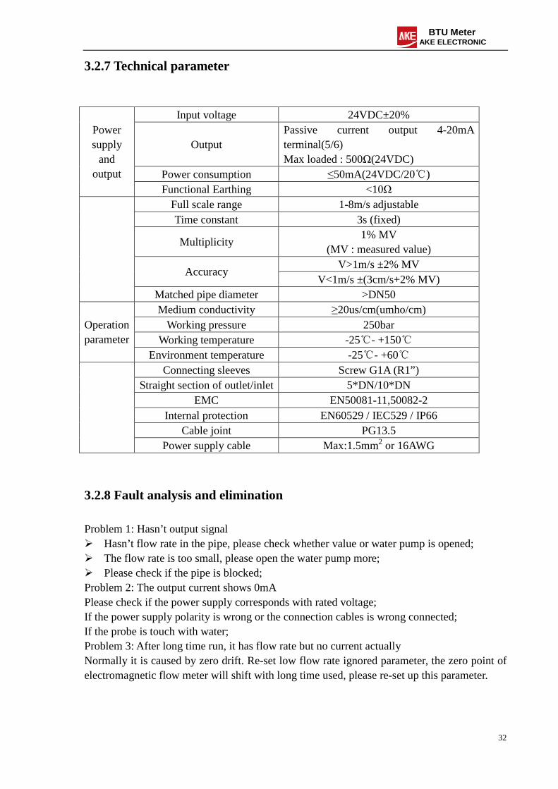
3.2.7 Technical parameter
Input voltage 24VDC±20%
Output Passive current output 4-20mA terminal(5/6) Max loaded : 500Ω(24VDC)
Power consumption ≤50mA(24VDC/20)
Power supply
and output
Functional Earthing <10Ω Full scale range 1-8m/s adjustable Time constant 3s (fixed)
Multiplicity 1% MV
(MV : measured value) V>1m/s ±2% MV
Accuracy V<1m/s ±(3cm/s+2% MV)
Matched pipe diameter >DN50 Medium conductivity ≥20us/cm(umho/cm)
Working pressure 250bar Working temperature -25- +150
Operation parameter
Environment temperature -25- +60 Connecting sleeves Screw G1A (R1”)
Straight section of outlet/inlet 5*DN/10*DN EMC EN50081-11,50082-2
Problem 1: Hasn’t output signal Hasn’t flow rate in the pipe, please check whether value or water pump is opened; The flow rate is too small, please open the water pump more; Please check if the pipe is blocked; Problem 2: The output current shows 0mA Please check if the power supply corresponds with rated voltage; If the power supply polarity is wrong or the connection cables is wrong connected; If the probe is touch with water; Problem 3: After long time run, it has flow rate but no current actually Normally it is caused by zero drift. Re-set low flow rate ignored parameter, the zero point of electromagnetic flow meter will shift with long time used, please re-set up this parameter.
33
BTU Meter AKE ELECTRONIC
Chapter four: Temperature sensor PT1000
4.1 General description
Hot resistance is a common temperature detector at middle-low temperature field, the characteristic is high accuracy and good stable performance. Platinum resistance thermometer is the highest accuracy type in that field, it is widely used at industrial field and even selected as a standard station meter. The measured principle is that with the temperature increased its resistance would be increased at the same time. Most of the hot resistance is make of metal, the common material is platinum and cooper, but nowadays the other materials such as nickel,
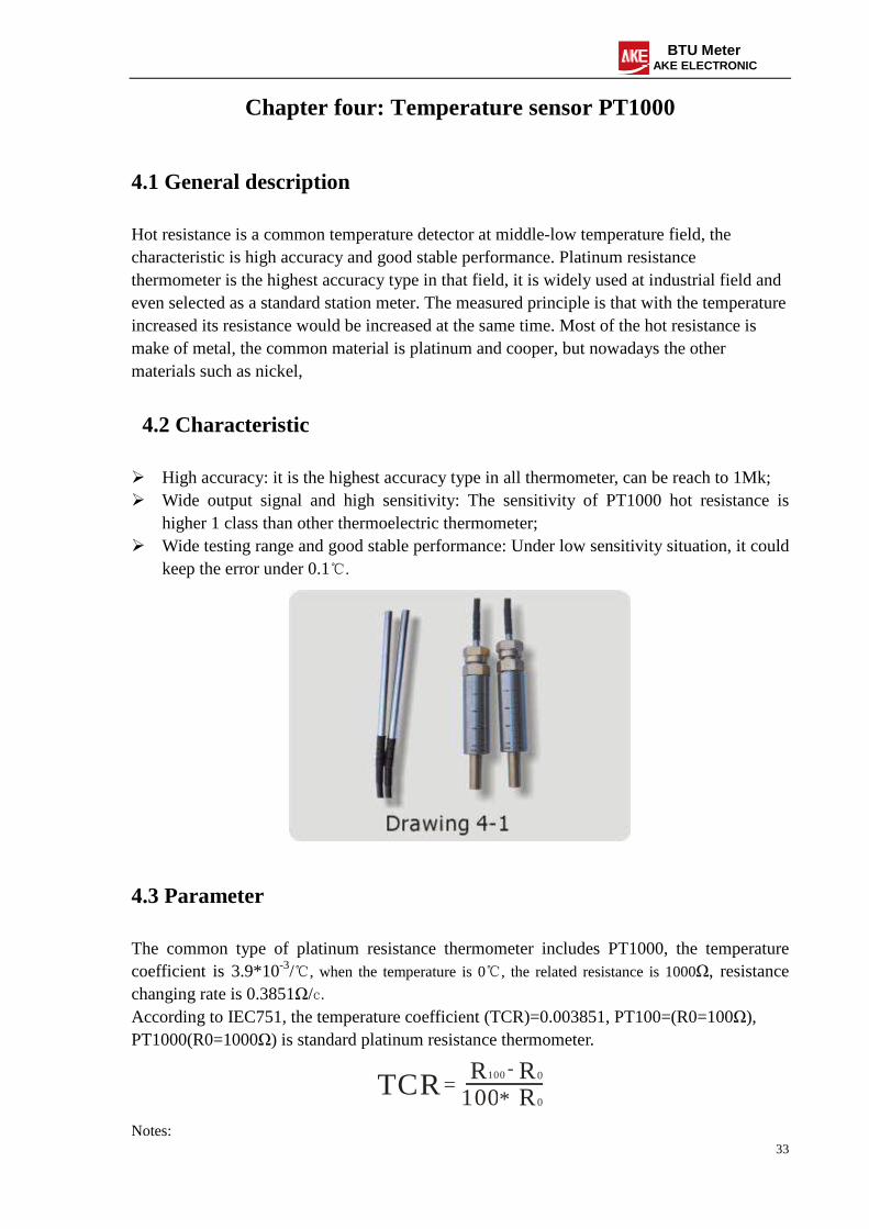
4.2 Characteristic
High accuracy: it is the highest accuracy type in all thermometer, can be reach to 1Mk; Wide output signal and high sensitivity: The sensitivity of PT1000 hot resistance is
higher 1 class than other thermoelectric thermometer; Wide testing range and good stable performance: Under low sensitivity situation, it could
keep the error under 0.1.
4.3 Parameter
The common type of platinum resistance thermometer includes PT1000, the temperature coefficient is 3.9*10-3/, when the temperature is 0, the related resistance is 1000Ω, resistance changing rate is 0.3851Ω/c. According to IEC751, the temperature coefficient (TCR)=0.003851, PT100=(R0=100Ω), PT1000(R0=1000Ω) is standard platinum resistance thermometer.
TCR=R100 0
100-R
* 0R
Notes:
34
BTU Meter AKE ELECTRONIC
R100: The resistance value when the temperature is 100
R0: The resistance value when the temperature is 0
4.4 PT1000 reference table
PT1000 reference table is the resistance value under different temperature. Via temperature value we can get the related resistance value or via resistance value we can get the related temperature value.
4.5 PT1000 installation
i) Opens a hole on the measured pipe, hole diameter is 30mm;
ii) Solders Fitting seat on measured pipe;
iii) Screws Sleeve into Fitting seat;
iv) Puts PT1000 into sleeve and inserts it on the bottom of sleeve and then screws it tightly.
Notes: Please make sure that the sleeve is tightly screwed into fitting seat in to make a good waterproof.


![PAX S80 User Guide · 11/2/2016 · Enter password and press [ENTER] 4. Select the payment type. Press [1] for a Credit return or [2] for a Debit return 5. Enter the amount of the](https://static.documents.pub/doc/80x56/5f5ed0999c5f004920521ec3/pax-s80-user-guide-1122016-enter-password-and-press-enter-4-select-the-payment.jpg)


