60
About this document BU 0040 GB-0113 Subject to technical alterations 1 GB BU 0040 Control and Parameter Boxes for NORD Frequency Inverters

About this document
BU 0040 GB-0113 Subject to technical alterations 1
GB
BU 0040 Control and Parameter Boxes for NORD Frequency Inverters

NORDAC Control and Parameter Boxes
2 Subject to technical alterations BU 0040 GB-0113
Intended use of the frequency inverter
The compliance with the operating instructions is necessary for fault-free operation and the acceptance of possible warranty claims. These operating instructions must be read before working with the device! These operating instructions contain important information about service. They must therefore be kept close to the device. The control and parameter boxes are only intended for use with NORD frequency inverters or their accessories (optional modules). All details regarding technical data and permissible conditions at the installation site must be complied with. Commissioning (implementation of the intended use) is not permitted until it has been ensured that the machine complies with the EMC directive 2004/108/EEC and that the conformity of the end product meets the machine directive 2006/42/EEC (note EN 60204).
Getriebebau NORD GmbH & Co. KG, 2013

About this document
BU 0040 GB-0113 Subject to technical alterations 3
Documentation
Designation: BU 0040 DE Part No.: 607 04 01 Device types: SK PAR-2H, SK PAR-2E, SK PAR-3H, SK PAR-3E SK CSX-3H, SK CSX-3E SK SSX-3A
1
SK POT1-1 SK TU3-CTR, SK TU3-PAR Suitable for frequency inverter series: NORD SK 200E, SK 300E
2, SK 500E, SK 700E, SK 750E
2
NORD vector mc2
Version list
Designation of previous versions Software Version
Comments
BU 0300 DE, August 2008
Part No. 607 0801 / 3208
V 3.9 R0 Revised version of issue 4907 (December 2007)
BU 0300 DE, March 2009
Part No. 607 0801 / 1009
V 4.0 R3 Addition of the products SK PAR-3H and SK CSX-3H
BU 0040 DE, April 2011
Part No. 607 0801 / 1611
V 4.2 R1 Restructuring of manual, addition of the products SK PAR-3E, SK CSX-3E, SK SSX-3A and SK POT1-1
BU 0040 GB, January 2013
Part No. 607 0401 / 0113
V 4.4 R0 Supplement of SK TU3-CTR and SK TU3 PAR
Supplement of adapter kit for attachment of an SK SSX 3A to an SK 2xxE frequency inverter
Revision of warnings and information notes
Publisher
Getriebebau NORD GmbH & Co. KG Rudolf- Diesel- Str. 1 D-22941 Bargteheide Germany http://www.nord.com/
Tel.: +49 (0) 45 32 / 289-0 Fax +49 (0) 45 32 / 289-2555
ATTENTION Supplementary Operating Instructions
This supplementary operating manual is only valid in conjunction with the operating manual supplied for the respective frequency inverter. This is an essential prerequisite for the availability of all the relevant information required for the safe commissioning of the frequency inverter.
1 Not for "vector mc"
2 Only SK PAR-2H and SK PAR-2E
NORDAC Control and Parameter Boxes
4 Subject to technical alterations BU 0040 GB-0113
1 GENERAL AND SAFETY INFORMATION ..................................................... 6 1.1 Features ................................................................................................................... 7
1.1.1 ParameterBox (SK PAR-xx and SK TU3-PAR) .......................................... 7 1.1.2 SimpleBox (SK CSX-3x und SK TU3-CTR) ................................................ 7 1.1.3 SetpointBox (SK SSX-3A) ........................................................................... 7 1.1.4 Control box (SK POT1-1) ............................................................................ 7
1.2 Delivery .................................................................................................................... 8 1.3 Scope of supply ...................................................................................................... 8 1.4 Certifications ........................................................................................................... 8
1.4.1 European EMC Directive ............................................................................. 8 1.4.2 RoHS compliance ....................................................................................... 8
2 PARAMETER BOXES .................................................................................... 9 2.1 Installation ............................................................................................................... 9
2.1.1 SK PAR-2H - Handheld Version ................................................................. 9 2.1.1.1 Connection to trio SK 300E/750E ................................................... 9 2.1.1.2 Connection variants ...................................................................... 10
2.1.2 SK PAR-2E - built-in version ..................................................................... 11 2.1.2.1 Mechanical installation in a control panel ..................................... 11 2.1.2.2 Electrical connection ..................................................................... 12 2.1.2.3 Connection to inverter .................................................................. 13
2.1.3 SK …-3H – Handheld Version .................................................................. 14 2.1.3.1 SimpleBox SK CSX-3H – Handheld Version................................ 14 2.1.3.2 ParameterBox SK PAR-3H – Handheld Version .......................... 14 2.1.3.3 Electrical Connection .................................................................... 14
2.1.4 SK …-3E - built-in version ......................................................................... 16 2.1.4.1 SimpleBox SK CSX-3E – Built-in Version .................................... 16 2.1.4.2 ParameterBox Version SK PAR-3E– Built-in Version .................. 16 2.1.4.3 Mechanical installation in a control panel ..................................... 17 2.1.4.4 Electrical Connection SK …-3E .................................................... 18
2.1.5 SK TU3-… – (only for SK 5xxE) ................................................................ 19 2.1.5.1 ControlBox SK TU3-CTR.............................................................. 19 2.1.5.2 ParameterBox SK TU3-PAR ........................................................ 19 2.1.5.3 Installing the technology unit ........................................................ 19
2.2 Functions of the Parameter Boxes .................................................................... 20 2.2.1 SimpleBox / ControlBox ............................................................................ 20
2.2.1.1 Display .......................................................................................... 20 2.2.1.2 Operation ...................................................................................... 21
2.2.2 ParameterBox ........................................................................................... 25 2.2.2.1 Display .......................................................................................... 25 2.2.2.2 ControlBox mode .......................................................................... 26 2.2.2.3 Operation ...................................................................................... 27 2.2.2.4 Data transfer with NORD CON (except for, SK TU3-PAR) .......... 32 2.2.2.5 Description of the system parameters .......................................... 34 2.2.2.6 Parameter display ......................................................................... 34 2.2.2.7 Inverter parameterisation.............................................................. 36 2.2.2.8 Parameter administration ............................................................. 36 2.2.2.9 Options ......................................................................................... 37
2.2.3 Table of possible error messages ............................................................. 38 2.3 Technical data ....................................................................................................... 40 2.4 Accessories for NORD parameterisation boxes (except SK TU3-xxx)........... 41
2.4.1 SK IC1-232/485 interface converter .......................................................... 41 2.4.2 Cable-Adapter assignment ........................................................................ 41
2.4.2.1 Adapter list .................................................................................... 41 2.4.2.2 Assignment of parameterisation box - frequency inverter ............ 42

Contents
BU 0040 GB-0113 Subject to technical alterations 5
3 CONTROLBOXES ........................................................................................ 43 3.1 SK SSX-3A – Simple Setpoint Box .................................................................... 43
3.1.1 Installation ................................................................................................. 43 3.1.2 Connection ................................................................................................ 44 3.1.3 Operating modes ....................................................................................... 45
3.1.3.1 Operating mode 485C (Control mode via RS485) ....................... 45 3.1.3.2 Operating mode IO-C (Control mode via DI1/DO1 of the SK 2xxE)
...................................................................................................... 47 3.1.3.3 Operating mode IO-S (Setpoint mode via DI1 of the frequency
inverter) ........................................................................................ 50 3.1.4 Technical data ........................................................................................... 53
3.2 Control box (SK POT1-1) ..................................................................................... 53 3.2.1 Installation ................................................................................................. 53
3.2.1.1 Overview ....................................................................................... 54 3.2.1.2 Control connections ...................................................................... 55
3.2.2 Parameterisation ....................................................................................... 57 3.2.3 Technical data ........................................................................................... 57
4 MAINTENANCE AND SERVICING INFORMATION .................................... 58
5 KEYWORD INDEX ....................................................................................... 59

NORDAC Control and Parameter Boxes
6 Subject to technical alterations BU 0040 GB-0113
1 General and safety information
DANGER! Danger due to electricity
Installation must be carried out by qualified personnel only, paying particular attention to safety and warning instructions (refer to the manual for the drive electronics (e.g. frequency inverter).
Insertion or removal of modules or electrical connections must only be carried out when no voltage is present. Detailed information can be found in the relevant manual for the drive electronics.
NORD control and parameter boxes enable parameterisation, control and display of the operating parameters of the inverter series NORD SK 200E, SK 300E, SK 500E, SK 700E, SK 750E and vector mc. Various versions of the control and parameter boxes are available. The box to be used with a particular inverter series can be obtained by reference to the overview tables in Sections 2.4.2, 3.1.2 and 3.2.1.
1. For service and commissioning directly on the system the handheld versions of the parameter boxes (SK PAR-2H, SK PAR-3H and SK CSX-3H) are recommended. These handheld units can be used for parameterisation and display.
2. The built-in versions of the parameter boxes (SK PAR-2E, SK PAR-3E and SK CSX-3E), for installation in a control panel enable control and monitoring of up to 5 frequency inverters (SK CSX-… 1 frequency inverters) in a control cabinet.
3. The Simple Setpoint Box SK SSX-3A is primarily intended to control SK 200E series frequency inverters and can be sued both as a handheld unit and a wall-mounted unit.
4. The SK POT1-1 control box is a simple manual control unit for the control of NORD frequency inverters with an enabling signal and setpoint. The control box can also be used as a wall-mounted unit.
5. The ControllBox SK TU3-CTR and the ParameterBox SK TU3-PAR are exclusively designed for use with the SK 5xxE frequency inverter series and are plugged directly into the technology unit slot of the frequency inverter.
The ParameterBox (SK PAR-xx or SK TU3-PAR) has a storage capacity which can store the complete data records for up to 5 inverters. In order to archive the data, the ParameterBox SK PAR-2x can be connected to a PC via an interface converter (SK IC1-232/485). In order to connect the SK PAR-3H, only a common USB connection cable (USB2.0 connection cable, A-series plug to B-series plug) is required. The NORD CON software necessary for this can be downloaded free of charge from the Getriebebau NORD internet page http://www.nord.com. It is also possible to transfer data from the PC to the ParameterBox. For this, a previously saved or created data set is required (see Section 2.2.2.4). This is then recognised by the NORD CON Software.

1 General information
BU 0040 GB-0113 Subject to technical alterations 7
1.1 Features
1.1.1 ParameterBox (SK PAR-xx and SK TU3-PAR)
Illuminated, high resolution LCD graphics screen Central unit for up to 5 inverters interlinked via RS 485 5 complete inverter data records can be stored in the memory, loaded and processed For use as a display for various operating parameters Automatic inverter detection Large-screen display of individual operating parameters Standardisation of individual operating parameters to display specific system data Control in various languages (see parameter (P1301)) Error message display in plain language Direct control of an inverter possible ControlBox function possible
only SK PAR-xx:
RS 485 communication interface (SK PAR-3H: RS 485 and RS 232) Supply voltage 4.5VDC to 30VDC 5V (or 24 V) direct current supply from the frequency inverter can be used SK PAR-2x: with interface converter (SK IC1-232/485) connection to a standard RS 232 PC interface;
SK PAR3H via USB interface. In this case no interface converter is required3
Protection class IP 54. For information, see Technical Data, Section 2.3.
1.1.2 SimpleBox (SK CSX-3x und SK TU3-CTR)
4-digit, 7-segment display For use as a display for various operating parameters Direct control of an inverter possible LEDs for parameter set display Saving of a complete inverter data set (only SK TU3-CTR)
only SK CSX-xx:
5V (or 24V) direct current supply directly from the frequency inverter can be used Protection class IP 54. For information, see Technical Data, Section 2.3.
1.1.3 SetpointBox (SK SSX-3A)
4-digit, 7-segment display 24V direct current supply direct from the frequency inverter can be used 3 operating modes with automatic detection (depending on the connection)
- RS485 in control mode (SK 2xxE, SK 300E, SK 5xxE, SK 700E*, SK 750E*) - IO communication in control mode (SK 2xxE only) - IO communication in setpoint mode (SK 2xxE only)
Protection class IP 54 Wall-mounting possible
* only with optional RS485 interface
1.1.4 Control box (SK POT1-1)
Direction switch with "0" position for selection of the direction of rotation of the drive unit 10kOhm potentiometer for the continuous setting of setpoints between 0 and 100% Approx. 3m long connecting cable with open ends for permanent connection to the relevant digital and
analog input terminals of the frequency inverter The box can be wall-mounted Protection class IP 66
3 For SK PAR-3H directly via USB port (USB2.0)

NORDAC Control and Parameter Boxes
8 Subject to technical alterations BU 0040 GB-0113
1.2 Delivery
Check the equipment immediately after delivery/unpacking for transport damage such as deformation or loose parts. If there is any damage, contact the carrier immediately and carry out a thorough assessment.
Important! This also applies even if the packaging is undamaged.
1.3 Scope of supply
Standard version: The scope of supply includes one of the following devices,
Type Version IP protection class Part Number Comments
SK PAR-2E Installation IP 54 - front panel 278910110
SK PAR-2H Handheld IP 54 278910100 Incl. connection cable: M12 plug connector, length approx. 3m
SK PAR-3E Installation IP 54 - front panel 275281414
SK PAR-3H Handheld IP 54, IP 20 on plug
275281014 Incl. connection cable: * RJ12-RJ12, length approx. 2m * USB, length approx. 1m
SK CSX-3E Installation IP 54 - front panel 275281413
SK CSX-3H Handheld IP 54, IP 20 on plug
275281013 Incl. connection cable: * RJ12-RJ12, length approx. 2m
SK SSX-3A Handheld (wall-mounting possible)
IP 54 275281513 Incl. M12 screw cable connector
SK POT1-1 Handheld (wall-mounting possible)
IP 66 278910120 Incl. connection cable: length approx. 3m
Incl. M16 screw cable connector for SK 2xxE, SK 300E, SK 750E
SK TU3-CTR Direct mounting on FI IP 20 275900090 Only SK 5xxE
SK TU3-PAR Direct mounting on FI IP 20 275900100 Only SK 5xxE
Available accessories: (For details see Section 2.4)
- Interface converter for connecting SK PAR-2x to a PC - Various adapter plugs for connecting the parameter boxes to NORD frequency inverters - Operating instructions as PDF file on CD ROM including NORD CON, (PC-based
parameterisation software) - also available free of charge under www.nord.com
1.4 Certifications
1.4.1 European EMC Directive
If the control and parameter boxes are installed according to the recommendations in this instruction manual, they meet all of the requirements of the EMC directive according to the EMC product standard for motor-operated systems EN 61800-3.
1.4.2 RoHS compliance
NORD control and parameter boxes are designed to be RoHS compliant according to Directive 2002/95/EEC.

2 Parameter Boxes – Installation
BU 0040 GB-0113 Subject to technical alterations 9
2 Parameter boxes
With the aid of parameter boxes it is possible to control or adapt the parameterisation of a frequency inverter or its intelligent optional modules (e.g field bus modules). The SimpleBox versions only allow access to the frequency inverter.
2.1 Installation
2.1.1 SK PAR-2H - Handheld Version
The SK PAR-2H ParameterBox is a compact control device for direct connection to the frequency inverter. A suitable connection cable with an M12 plug contact is included with the device. Direct connection of the ParameterBox to the NORD SK 300E and the SK 750E is possible without additional components. Special connection cables are required for connection to other NORD frequency inverters. These are described in further detail in Section 2.1.1.2 "Connection variants".
2.1.1.1 Connection to trio SK 300E/750E
Direct connection to the trio SK 300E can be made using the available M12 socket. With the appropriate components the high level of protection (IP54) is retained for the entire unit. After the mains voltage is switched on the corresponding device type is automatically recognised.
M12 plug Description Cable
2 (white) + 4.5V… 30V, approx. 1.3 W
Length 3m
4 x 0.75mm2
1 (brown) GND
4 (black) P+ (A) (RS485 +)
3 (blue) P- (B) (RS485 -)
M12 - socket Frequency inverter
1
4
2
3

NORDAC Control and Parameter Boxes
10 Subject to technical alterations BU 0040 GB-0113
2.1.1.2 Connection variants
NO
RD
AC
Fre
qu
en
cy
in
ve
rter
trio
SK
300
E
SK
750 E
SK
52x
E
SK
53x
E
vecto
r m
c
SK
700
E
SK
5xx
E
SK
200
E
SK
700
E
(>2
2K
W)
PC
/ l
ap
top
NO
RD
CO
N
So
ftw
are
Mo
du
les
/op
tio
ns
Dir
ect
to s
yste
m c
on
necto
r Dir
ec
t to
te
rmin
als
(RS
48
5)
S
K C
U1
-ST
D
SK
CU
1-U
SS
Dir
ec
t c
on
ne
cti
on
to d
ev
ice
S
K I
C1
-23
2/4
85
Pa
rt.
No
. 27
697
00
20
+
US
B 5
V A
da
pte
r
Pa
rt.
No
. 27
891
02
20
Co
nn
ec
tin
g c
ab
le
Co
nn
ec
tio
n c
ab
le M
12
so
cke
t–>
wir
es
M1
2 S
o /
wir
es
Pa
rt.
No
. 27
891
02
00
C
on
ne
cti
on
ca
ble
M1
2 s
oc
ke
t ->
RJ12
RH
12
/ M
12
S
o
Pa
rt.
No
. 27
891
02
30
C
on
ne
cti
on
ca
ble
M1
2 s
oc
ke
t ->
SU
B-D
M1
2 S
o /
Sub
-D S
o
Pa
rt.
No
. 27
891
02
10
Para
mete
rBo
x
SK
PA
R-2
H
Part
. N
o. 2
789
101
00
2 Parameter Boxes – Installation
BU 0040 GB-0113 Subject to technical alterations 11
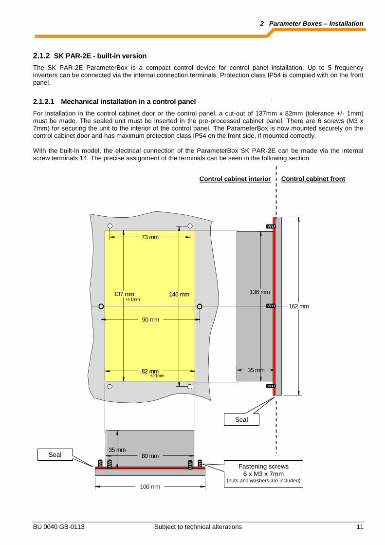
2.1.2 SK PAR-2E - built-in version
The SK PAR-2E ParameterBox is a compact control device for control panel installation. Up to 5 frequency inverters can be connected via the internal connection terminals. Protection class IP54 is complied with on the front panel.
2.1.2.1 Mechanical installation in a control panel
For installation in the control cabinet door or the control panel, a cut-out of 137mm x 82mm (tolerance +/- 1mm) must be made. The sealed unit must be inserted in the pre-processed cabinet panel. There are 6 screws (M3 x 7mm) for securing the unit to the interior of the control panel. The ParameterBox is now mounted securely on the control cabinet door and has maximum protection class IP54 on the front side, if mounted correctly. With the built-in model, the electrical connection of the ParameterBox SK PAR-2E can be made via the internal screw terminals 14. The precise assignment of the terminals can be seen in the following section.
137 mm
82 mm
136 mm
162 mm
35 mm
80 mm35 mm
100 mm
73 mm
146 mm
90 mm
+/-1mm
+/-1mm
Control cabinet front Control cabinet interior
Seal
Fastening screws 6 x M3 x 7mm
(nuts and washers are included)
Seal

NORDAC Control and Parameter Boxes
12 Subject to technical alterations BU 0040 GB-0113
2.1.2.2 Electrical connection
The SK PAR-2E ParameterBox is connected via the 6-pin screw connector or the RJ12 plug. The power supply can either be from the inverter or a separate supply unit. The permissible voltage range is +4.5V to +30V DC.
Number Description RJ 12
42 + 4.5V… 30V / 1.3W 6
VR
EF
10
V
AG
ND
0V
AIN
1+
AIN
2+
AO
UT
1
DIG
IN
1
DIG
IN
2
DIG
IN
3
DIG
IN
4
VO
+1
5V
DG
ND
0V
11
12
13
14
16
22
23
24
25
42
40
21
DIG
IN
5
1 2 3 4R
EL
2.2
RE
L 2
.1
RE
L1
.2
RE
L 1
.1
CA
N_
H
CA
N_
L
CA
N_
GN
D
nc
CA
N_
SH
LD
CA
N_
GN
D
nc
CA
N_
24
V
CA
N_
H
CA
N_
L
CA
N_
GN
D
nc
CA
N_
SH
LD
CA
N_
GN
D
nc
CA
N_
24
V
RS
48
5_
A
RS
48
5_
B
GN
D
TX
D
RX
D
41
VO
+5
V
+5
V
+
5V
- 3
0V
1 2 3 4 5 6
40 GND 3
73 P+ (A) (RS485 +) 1
74 P- (B) (RS485 -) 2
- - 4
- - 5
A termination resistor (220) for the RS485 bus system is integrated into the module. Therefore the ParameterBox should only be connected as the first or last participant. The terminals are designed for 0.14 mm² - 1.5 mm
2. A flexible cable with a cross section of 4 x 0,75mm
2 is
recommended. The maximum possible connection cross section is 1.5mm
2. With the use of certain wire end sleeves, the possible
cross-section may be reduced.
Schaltschrank
Gear unit motor with FI in field
SK PAR-2E Part No. 278910110
SK 5xxE SK 700E vector CT
SK 2xxE SK 300E SK 750E
vector mc
Power supply Data cable

2 Parameter Boxes – Installation
BU 0040 GB-0113 Subject to technical alterations 13
2.1.2.3 Connection to inverter
A shielded signal cable should be used for the data cable between the ParameterBox and the inverter. The power supply to the ParameterBox must be between +4.5V and +30V. Please use the following connections to connect the ParameterBox with the corresponding inverter. The connections apply for fixed connection to the particular inverter via the terminal bar. However, these must always be compared with the labelling on the ParameterBox.
Description vector mc
RS485
vector
(CT / VT) SK 300E
SK 52xE and higher
X7:
SK 700E / SK 750E
(with option…)
SK CU1-STD SK CU1-USS
+5V / +15V 15 - 42 42 42 42
GND 16 - 40 40 40 40
P+ (A), RS485 + 17 21 73 73 73 73
P- (B), RS485 - 18 22 74 74 74 74
ATTENTION Damage to the RS485
Each further frequency inverter which is to be operated simultaneously on the bus cable is only connected in parallel to the cables RS485+ and RS485-.
Under no circumstances may the power supplies of the frequency inverters (5V) be connected to each other.
For the following series of devices the RS485 data connection is also possible via the RJ12 plug socket which is integrated into the inverter.
Description
SK 2xxE
Integrated 6-pin RJ12
socket
SK 300E
Integrated 4-pin M12 connector
SK 5xxE
Integrated 6-pin RJ12
socket
SK 700E >22KW
Integrated 6-pin RJ12
socket
SK 700E ≤22KW
(with option …-RS2)
Integrated 6-pin RJ12
socket
SK 750E
Integrated 4-pin M12 connector
+5V 6 ("24V") 2 6 6 (6) * 2
GND
3 1 3 3 (3) * 1
P+ (A) (RS485 +)
1 4 1 1 1 4
P- (B) (RS485 -)
2 3 2 2 2 3
* For inverters SK700E up to 22KW with the option …-RS2 an external power supply (+4.5V - + 30V) must be provided for the ParameterBox.
In order to connect the ParameterBox to the RJ12 socket of the frequency inverter, a standard RJ12 (6-pole) patch cable with a length of up to 3 m can be used. As standard, the 4-pin M12 connector (plug) is available for connection of the ParameterBox to a decentralised frequency inverter (SK 300E/ SK750E). If the ParameterBox is supplied from an external power source (+4.5 to +30V) according to the voltage, the data cables can also be considerably longer.
ATTENTION Voltage level of external supply
In order to avoid damage, if an external power supply to the ParameterBox is used, care must be taken that the output voltage of this external source is higher than that of the inverter voltage (however, max. 30V DC).
(E.g.: SK520E: 5V internal supply→ External supply for the ParameterBox >5V!)

NORDAC Control and Parameter Boxes
14 Subject to technical alterations BU 0040 GB-0113
2.1.3 SK …-3H – Handheld Version
2.1.3.1 SimpleBox SK CSX-3H – Handheld Version
The SK CSX-3H SimpleBox is a compact control device for direct connection to the frequency inverter via the RJ12 diagnostic socket. A normal RJ12 -patch cable ("Modular cable RJ12 (6/6) - RJ12 (6/6), 1:1 assignment") with a length of up to 3m can be used for connection. If the SimpleBox is supplied from a power source with a higher voltage (e.g. 24VDC from SK 200E), the cable can be considerably longer.
2.1.3.2 ParameterBox SK PAR-3H – Handheld Version
The SK PAR-3H ParameterBox is a compact control device for direct connection to the frequency inverter via the RJ12 diagnostic socket. A normal RJ12 -patch cable ("Modular cable RJ12 (6/6) - RJ12 (6/6), 1:1 assignment") with a length of up to 3m can be used for connection. If the ParameterBox is supplied from a power source with a higher voltage (e.g. 24VDC from SK 200E), the cable can be considerably longer. A normal USB device connection cable (USB2.0 connection cable, Series A plug to Series B plug) is required to connect a PC or laptop.
ATTENTION Damage to PC
The SK PAR-3H ParameterBox must never be connected simultaneously to the frequency inverter and the PC, as otherwise this may cause damage, especially to the PC.
2.1.3.3 Electrical Connection
The parameter boxes SK CSX-3H and SK PAR-3H are only connected to a frequency inverter via the RJ12 socket. This connection also provides the power supply to the box.
A termination resistor (220) for the RS485 bus system is integrated into the module. Therefore the ParameterBox should only be connected as the first or last participant. Connection of the SK PAR-3H ParameterBox to a PC is made via the USB interface integrated into the box. This connection also provides the power supply to the box. The necessary driver software for the USB interface on the PC is supplied with the enclosed CD "EPD", but is also available free of charge on our Internet page (www.nord.com).
RJ12 (RS485)
USB port

2 Parameter Boxes – Installation
BU 0040 GB-0113 Subject to technical alterations 15
Connection to the particular frequency inverter is made via the RJ12 connection sockets on the device. The SimpleBox SK CSX-3H can only communicate with frequency inverters.
The contact assignment of the RJ-12 connection on the parameter box is as follows:
Description RJ 12
P+ (A) RS 485 + 1
VR
EF
10
V
AG
ND
0V
AIN
1+
AIN
2+
AO
UT
1
DIG
IN
1
DIG
IN
2
DIG
IN
3
DIG
IN
4
VO
+1
5V
DG
ND
0V
11
12
13
14
16
22
23
24
25
42
40
21
DIG
IN
5
1 2 3 4R
EL
2.2
RE
L 2
.1
RE
L1
.2
RE
L 1
.1
CA
N_
H
CA
N_
L
CA
N_
GN
D
nc
CA
N_
SH
LD
CA
N_
GN
D
nc
CA
N_
24
V
CA
N_
H
CA
N_
L
CA
N_
GN
D
nc
CA
N_
SH
LD
CA
N_
GN
D
nc
CA
N_
24
V
RS
48
5_
A
RS
48
5_
B
GN
D
TX
D
RX
D
41
VO
+5
V
+5
V
+4.5
V -
30V
1 2 3 4 5 6
P- (B) RS 485 - 2
GND 3
- 4
- 5
+ 4.5V… 30V, approx.1.3 W
6
SK TI4-TU-BUS
SK200E SK700E SK500E
NORDAC Control and Parameter Boxes
16 Subject to technical alterations BU 0040 GB-0113
2.1.4 SK …-3E - built-in version
The SK CSX-3E and SK PAR3E are built-in versions of the parameter boxes described in Section 2.1.3. If they are correctly installed in the front of the control panel they comply with protection class IP 54.
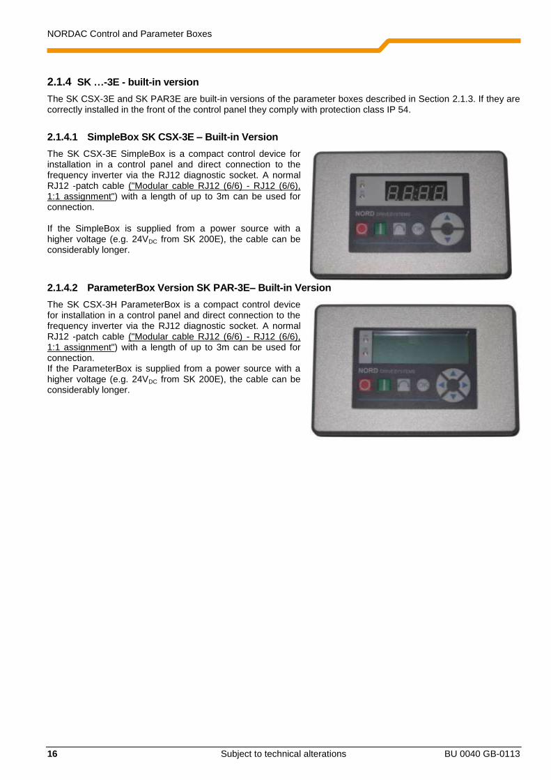
2.1.4.1 SimpleBox SK CSX-3E – Built-in Version
The SK CSX-3E SimpleBox is a compact control device for installation in a control panel and direct connection to the frequency inverter via the RJ12 diagnostic socket. A normal RJ12 -patch cable ("Modular cable RJ12 (6/6) - RJ12 (6/6), 1:1 assignment") with a length of up to 3m can be used for connection. If the SimpleBox is supplied from a power source with a higher voltage (e.g. 24VDC from SK 200E), the cable can be considerably longer.
2.1.4.2 ParameterBox Version SK PAR-3E– Built-in Version
The SK CSX-3H ParameterBox is a compact control device for installation in a control panel and direct connection to the frequency inverter via the RJ12 diagnostic socket. A normal RJ12 -patch cable ("Modular cable RJ12 (6/6) - RJ12 (6/6), 1:1 assignment") with a length of up to 3m can be used for connection. If the ParameterBox is supplied from a power source with a higher voltage (e.g. 24VDC from SK 200E), the cable can be considerably longer.

2 Parameter Boxes – Installation
BU 0040 GB-0113 Subject to technical alterations 17
2.1.4.3 Mechanical installation in a control panel
For installation in the control cabinet door or the control panel, a cut-out of 109mm x 64mm (tolerance +/- 1mm) must be made. The sealed unit must be inserted in the pre-processed cabinet panel. For attachment to the inside of the control panel, 6 threaded pins (M4 x 16 mm) (approx. 7 mm projection in installed condition) and the corresponding nuts are provided. The ParameterBox is now mounted securely on the control cabinet door and has maximum protection class IP54 on the front side, if mounted correctly. Electrical connection of the SK CSX-3E or SK PAR-3E parameterisation boxes is made via the RJ12 socket which is accessible from the rear. The precise assignment of the terminals can be seen in the following section.
Control cabinet front Control cabinet interior
Seal
Fastening bolts 6 x M4 x 16mm
(nuts and washers are included)
Seal

NORDAC Control and Parameter Boxes
18 Subject to technical alterations BU 0040 GB-0113
2.1.4.4 Electrical Connection SK …-3E
The parameter boxes SK CSX-3E and SK PAR-3E are only connected to a frequency inverter via the RJ12 socket. This connection also provides the power supply to the box.
A termination resistor (220) for the RS485 bus system is integrated into the module. Therefore the ParameterBox should only be connected as the first or last participant. In contrast to the handheld version SK PAR-3H, connection of the SK PAR-3E ParameterBox to a PC is not possible. Connection to the particular frequency inverter is made via the RJ12 connection sockets on the device. The SimpleBox SK CSX-3E can only communicate with frequency inverters.
The contact assignment of the RJ-12 connection on the parameter box is as follows:
Description RJ 12
P+ (A) RS 485 + 1
VR
EF
10
V
AG
ND
0V
AIN
1+
AIN
2+
AO
UT
1
DIG
IN
1
DIG
IN
2
DIG
IN
3
DIG
IN
4
VO
+1
5V
DG
ND
0V
11
12
13
14
16
22
23
24
25
42
40
21
DIG
IN
5
1 2 3 4R
EL
2.2
RE
L 2
.1
RE
L1
.2
RE
L 1
.1
CA
N_
H
CA
N_
L
CA
N_
GN
D
nc
CA
N_
SH
LD
CA
N_
GN
D
nc
CA
N_
24
V
CA
N_
H
CA
N_
L
CA
N_
GN
D
nc
CA
N_
SH
LD
CA
N_
GN
D
nc
CA
N_
24
V
RS
48
5_
A
RS
48
5_
B
GN
D
TX
D
RX
D
41
VO
+5
V
+5
V
+4.5
V -
30V
1 2 3 4 5 6
P- (B) RS 485 - 2
GND 3
- 4
- 5
+ 4.5V… 30V, approx.1.3 W
6
SK TI4-TU-BUS
SK500E SK200E
RJ12 (RS485)
Rear of parameterisation box Similar to illustration
SK700E

2 Parameter Boxes – Installation
BU 0040 GB-0113 Subject to technical alterations 19
2.1.5 SK TU3-… – (only for SK 5xxE)
2.1.5.1 ControlBox SK TU3-CTR
The SK TU3-CTR ControlBox is used for the commissioning, configuration and control of the SK 5xxE frequency inverter. It is mounted directly on the slot for the technology units. Communication with the inverter and the power supply of the module are provided by a contact strip The module cannot be used independently from the inverter. The display is via a 4-digit, 7-segment display. Control is via 6 control buttons. The parameters of an inverter can be saved.
2.1.5.2 ParameterBox SK TU3-PAR
The SK TU3-PAR ParameterBox is used for the commissioning, configuration and control of the SK 5xxE frequency inverter. It is mounted directly on the slot for the technology units. Communication with the inverter and the power supply of the module are provided by a contact strip The module cannot be used independently from the inverter. The display is via a 4-line LED display. Control is via 8 control buttons. The parameters of 5 inverters can be saved.
2.1.5.3 Installing the technology unit
Modules must not be inserted or removed unless the device is free of voltage. The slots may only be used for the intended modules. Installation of a technology unit separate from the frequency inverter is not possible. It must be connected directly to the frequency inverter. The Installation of the technology units must be carried out as follows:
1. Switch off the mains voltage, observe the
waiting period.
2. Push the control terminals cover down
slightly or remove.
3. Remove the blank cover, by releasing the
catch at the lower edge and turning it
upwards.
4. Hook the technology unit onto the upper
edge slots and press in lightly until it
engages. Ensure full contact with the
connector strip and fasten with the screws if
necessary.
5. Close the control terminal cover again.

NORDAC Control and Parameter Boxes
20 Subject to technical alterations BU 0040 GB-0113
P1
P2
P1
P2
P1
P2
P1
P2
2.2 Functions of the Parameter Boxes
2.2.1 SimpleBox / ControlBox
2.2.1.1 Display
After connection/installation of the Box and switching on the mains voltage (or the 24V DC control voltage) of the frequency inverter, communication between the frequency inverter and the Box commences automatically. After brief illumination of all he display segments and diodes of the box a bus scan is carried out while the middle bars of the display (4-digit, 7-segment display) may flash rapidly. If the bus scan is completed successfully, the frequency inverter power appears briefly in the display (e.g.: 0.37 = 0.37 KW). This step is skipped if the Box is connected to a frequency inverter which is already in operation.
The horizontal bars which then appear in the display indicate that the frequency inverter is ready for operation. If a jog frequency value is pre-set in parameter P113, or a minimum frequency is pre-set in P104, the display flashes with this initial value. If the frequency inverter is enabled, the display changes automatically to the operating value selected in parameter >Selection Display value< P001 (factory setting = current frequency). The actual parameter set is shown by the 2 LEDs next to the display on the left in binary code. After the frequency inverter is switched off, an "OFF" appears briefly in the display before the display is completely switched off. "OFF" is also shown in the display if the SimpleBox is operated via an external 24V control voltage, although the power supply (230V or 400V) is inactive. In this state, almost unrestricted parameterisation of the inverter (no measurement of motor resistance or parameter identification is possible (P208 / P220)) can be carried out as described in the following section. However, control (enabling) is not possible due to the lack of the power supply.
Information Setpoint
The digital frequency setpoint is factory set to 0Hz. To check whether the motor is working, a frequency setpoint
must be entered with the or keys or a jog frequency via the respective parameter >Jog frequency< (P113).
WARNING Danger of injury if motor starts
The motor may start immediately after pressing the START key !
2 Parameter Boxes – Display and control
BU 0040 GB-0113 Subject to technical alterations 21
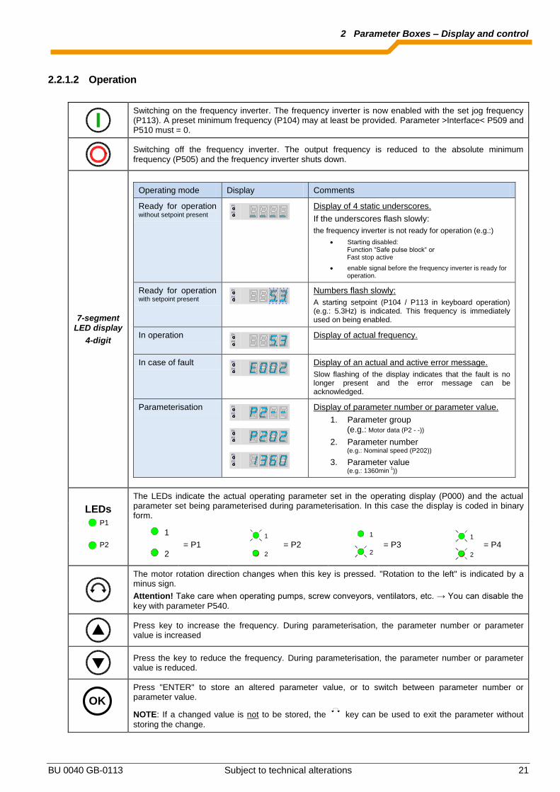
2.2.1.2 Operation
Switching on the frequency inverter. The frequency inverter is now enabled with the set jog frequency (P113). A preset minimum frequency (P104) may at least be provided. Parameter >Interface< P509 and P510 must = 0.
Switching off the frequency inverter. The output frequency is reduced to the absolute minimum frequency (P505) and the frequency inverter shuts down.
7-segment LED display
4-digit
Operating mode Display Comments
Ready for operation without setpoint present
Display of 4 static underscores.
If the underscores flash slowly:
the frequency inverter is not ready for operation (e.g.:)
Starting disabled: Function “Safe pulse block“ or Fast stop active
enable signal before the frequency inverter is ready for operation.
Ready for operation with setpoint present
Numbers flash slowly:
A starting setpoint (P104 / P113 in keyboard operation) (e.g.: 5.3Hz) is indicated. This frequency is immediately used on being enabled.
In operation
Display of actual frequency.
In case of fault
Display of an actual and active error message.
Slow flashing of the display indicates that the fault is no longer present and the error message can be acknowledged.
Parameterisation
Display of parameter number or parameter value.
1. Parameter group (e.g.: Motor data (P2 - -))
2. Parameter number (e.g.: Nominal speed (P202))
3. Parameter value (e.g.: 1360min
-1))
LEDs
P1
P2
The LEDs indicate the actual operating parameter set in the operating display (P000) and the actual parameter set being parameterised during parameterisation. In this case the display is coded in binary form.
1
2
= P1 2
1
= P2
1
2
= P3 2
1
= P4
The motor rotation direction changes when this key is pressed. "Rotation to the left" is indicated by a minus sign.
Attention! Take care when operating pumps, screw conveyors, ventilators, etc. → You can disable the
key with parameter P540.
Press key to increase the frequency. During parameterisation, the parameter number or parameter value is increased
Press the key to reduce the frequency. During parameterisation, the parameter number or parameter value is reduced.
Press "ENTER" to store an altered parameter value, or to switch between parameter number or parameter value.
NOTE: If a changed value is not to be stored, the key can be used to exit the parameter without
storing the change.
OK
P1
P2
P1
P2
P1
P2
P1
P2
P1
P2
P1
P2
P1
P2

NORDAC Control and Parameter Boxes
22 Subject to technical alterations BU 0040 GB-0113
Control with the SimpleBox / ControlBox
The frequency inverter can only be controlled via the SimpleBox, if it has not previously been enabled via the control terminals or via a serial interface (P509 = 0 and P510 = 0). As well as this, with the series SK 500E and SK 700E no technology unit (SK TU3-PAR or SK TU1-PAR) may be plugged into the inverter. If the "START" key is pressed, the frequency inverter in the operating display changes (selection P001). The frequency inverter supplies 0Hz or the minimum frequency (P104) or jog frequency (P113) which has been set. The following illustration is for the SimpleBox and applies accordingly for the ControlBox.
Parameter set display: The LEDs indicate the actual operating parameter set in the operating display (P000) and the current parameter set
being parameterised ( P000). In this case, the display appears in binary form. The parameter set can also be changed during operation via the parameter P100 (control via SimpleBox). Frequency setpoint: The current frequency setpoint depends on the setting in the parameters jog frequency (P113) and minimum
frequency (P104). This value can be altered during keyboard operation with the value keys and permanently stored in P113 as the jog frequency by pressing the ENTER key. Frequency addition (only SK 5xxE): If the parameter “PotentiometerBox Function” (P549) has been set to function 4”Frequency addition” or function 5 “Frequency subtraction”, as of software version 1.7 of the inverter a setpoint can be added via the Box, even if enabling and other setpoints are provided from another source (control terminals, BUS). However, after the drive unit has been shut down, this additive setpoint is reset to zero. By pressing the ENTER key however, the set value is permanently stored in parameter P113 as the jog frequency, and continues to be available as a setpoint value on re-enabling after shutdown. Emergency stop (only SK TU3-CTR):
By simultaneously pressing the STOP key and the "Change direction key” , an emergency stop can be initiated. Information for the SimpleBox (SK CSX-3x) No technology unit (SK TUx-PAR) may be plugged in if SK 500E and SK 700E series inverters are used. Otherwise, communication errors can be expected.
P1
P2
NORD DRIVESYSTEMS
OK
SK CSX-3H
STOP (no enable)
START (enable)
Rotation direction reversal
Store current frequency
Increase / decrease the frequency, or set it to "0" if simultaneously pressed
Parameter set display
P set No.. P1 P2
1 Off Off 2 On Off 3 Off On 4 On On

2 Parameter Boxes – Display and control
BU 0040 GB-0113 Subject to technical alterations 23
Parameterisation with the SimpleBox / ControlBox
The parameterisation of the frequency inverter can be performed in the various operating states. All parameters can always be changed online. Switching to the parameter mode occurs in different ways depending upon the operating states and the enabling source.
1. If there is no enable (if necessary, press the STOP key ) via the SimpleBox, the control terminals or a serial interface, it is still possible to switch to the parameterisation mode directly from the operating value
display with the value keys or . P 0 _ _ ... P 7 _ _ 2. If an enable is present via the control terminals or a serial interface and the frequency inverter is producing
an output frequency, it is also possible to switch to the parameterisation mode directly from the operating
value display using the value keys or . P 0 _ _ ... P 7 _ _ 3. If the inverter is enabled via the ControlBox (START key ), the parameterisation mode can be accessed
by pressing the START and ENTER keys ( + or ) simultaneously.
4. Switching back to the control mode is achieved by pressing the START key . The following illustration is for the SimpleBox and applies accordingly for the ControlBox.
Changing parameter values
To access the parameter section, one of the value keys, or must be pressed. The display changes to the
menu group display P 0 _ _ ... P 7 _ _ . After pressing the ENTER key or , access to the menu group is
obtained and the required parameter can be selected with the value keys. All parameters are arranged in order in the individual menu groups in a continuous scroll pattern. It is therefore possible to scroll forwards and backwards within this section. Each parameter has a parameter number P x x x . The significance and description of the parameters starts in Section 5 "Parameterisation"
OK
OK
P1
P2
NORD DRIVESYSTEMS
OK
SK CSX-3H
Select menu group or
display parameter value or adopt parameter value
Select function
Next menu group or parameter number
Value -
+
Load factory setting
Parameter set display
P set No.. P1 P2
1 Off Off 2 On Off 3 Off On 4 On On
Switch from parameterisation to control
(with enable (START))
Value +
Previous menu group or parameter number
Value function
One menu level back or do not adopt changed value
Pressed simultaneously: Switching from control to
parameterisation while the drive is running
Switch from parameterisation to control (without enable (STOP))

NORDAC Control and Parameter Boxes
24 Subject to technical alterations BU 0040 GB-0113
NOTE: Some parameters, e.g.: P465, P475, P480…P483, P502, P510, P534, P701…P706, P707, P718,
P740/741 and P748 (depending on the inverter series) have additional levels (arrays), in which further settings can be made, e.g.:
P_01 P502
P_02
of f
of f
Setting: Value of master function 1
Setting: Value of master function 2
ENTER ENTER
ENTER
VALUE
Menu structure with the SimpleBox
P0--
_ _ _ _
P1-- P2--
P4--
P5--
P6-- P7--
P001
P002
P100
P101
P114
P200
P201
P220
P400
P401
P483
Operating value display (or operational)
following mains ON
P3--
P300
P301
P327
P003
To change a parameter value, the ENTER key or OK
must be pressed when the relevant parameter number is displayed.
Changes can then be made using the VALUE keys or and must be confirmed with OK
to save them and leave the parameter. As long as a changed value has not been confirmed by pressing ENTER , the value display will flash; this value has not yet been stored in the frequency inverter.
If a change is not to be saved, the "DIRECTION" key can be pressed to leave the parameter.

2 Parameter Boxes – Display and control
BU 0040 GB-0113 Subject to technical alterations 25
2.2.2 ParameterBox
2.2.2.1 Display
After the initial commissioning of the ParameterBox, a query is made as to whether the menu language should be German or English Then, or after each new commissioning of the Box an automatic "Bus-Scan" is performed. The ParameterBox identifies the connected frequency inverter(s). The frequency inverter type and its current operating status can be seen in the following display.
300E 0,75kW/3 BSC … 1
> NORDAC < Frequency inverter
ONLINE I1 P1 Ready
In the standard display mode, 3 operating values and the current frequency inverter status can be displayed simultaneously. The operating values displayed can be selected from a list of 8 possible values (in Menu>Display</>Values for display<(P1004)).
300E 0,75kW/3 BSC … 1
Fi/Hz U/V I/A 45.0 190 1.4 ONLINE I1 P1 R RUNNING
Current status of the inverter
Inverter type
Current actual values for the selected operating values and their applicable units
Current ParameterBox status
Inverter selected
Active parameters in inverter
Current status of the inverter
Inverter type
Menu structure level
Customer's interface, special expansion

NORDAC Control and Parameter Boxes
26 Subject to technical alterations BU 0040 GB-0113
2.2.2.2 ControlBox mode
Above firmware version 3.7 a further display mode (ControlBox) can be selected. If this mode is selected by the user, the displays for the ControlBox (LED display of active parameter set and 4-digit "7-segment display") are shown on the screen. This mode also enables access to new parameters of an inverter, even if these parameters have not yet been implemented in the firmware of the ParameterBox. (Example: an inverter with current firmware version is to be parameterised with a ParameterBox with an older firmware version)
1 O _ _ _ _
O
ONLINE I1 P1 Ready
Information Setpoint
The digital frequency setpoint is factory set to 0Hz. To check whether the motor is working, a frequency setpoint
must be entered with the or keys or a jog frequency via the respective parameter >Jog frequency< (P113).
WARNING Danger of injury if motor starts
The motor may start immediately after pressing the START key !
Operating display (digit)
Parameter set display via LED symbols, similar to SimpleBox (see section 4.1.2) (siehe Kap. 4.1.2)

2 Parameter Boxes – Display and control
BU 0040 GB-0113 Subject to technical alterations 27
2.2.2.3 Operation
LCD display Graphic-capable, backlit LCD display for displaying operational values and parameters for the connected frequency inverter(s) and ParameterBox parameters.
Use the Selection keys to move through the menu levels and within the individual menu items.
Press the and keys together to go back one level.
The contents of individual parameters can be altered with the VALUES keys.
Press the and keys together to load the default values of the parameter selected.
When controlling the inverter using the keyboard, the frequency setpoint is set using the VALUE keys.
or
Press the ENTER key to select a menu group or accept the changed menu item or parameter value.
Note: If a parameter is to remain, without a new value being stored, then one of the SELECTION keys can be used for the purpose.
If the inverter is to be controlled directly from the keyboard (not control terminals), then the actual setpoint frequency can be stored under the Jog Frequency parameter (P113).
START key for switching on the frequency inverter.
Note: Can only be used if this function has not been blocked in
parameter P509 or P540.
STOP key for switching off the frequency inverter.
The direction of rotation of the motor changes when the DIRECTION key is operated. Rotation direction left is indicated by a minus sign.
Attention! Take care when operating pumps, screw conveyors, ventilators, etc. → You can disable the key with parameter P540.
The LED's indicate the actual status of the ParameterBox.
DS (ON (green)) Device State
The ParameterBox is connected to the power supply and is operational.
DE (ERROR (red)) Device Error
An error has occurred in the processing or communication of the data or in the connected frequency inverter.
DS
DE
OK

NORDAC Control and Parameter Boxes
28 Subject to technical alterations BU 0040 GB-0113
Control of the inverter
The speed and direction of rotation of the inverter can be fully controlled via the ParameterBox. Different settings are necessary according to the inverter series.
Series Parameter setting (P509) Comments
SK 200E 0 "Control terminal or keyboard" Control with the ParameterBox is only possible if no enable has been carried out via the control terminals. (The interface which is used first has priority.)
SK 300E 0 "Control terminal or keyboard" Control with the ParameterBox is only possible if no enable has been carried out via the control terminals. (The interface which is used first has priority.)
SK 500E For the use of an SK PAR-2x or SK PAR-3x:
2 "USS" No further control via the control terminals or the keyboard of a plugged in technology unit is possible.
For the use of an SK TU3-PAR:
0 "Control terminal or keyboard" Control with the ParameterBox is only possible if no enable has been carried out via the control terminals. (The interface which is used first has priority.)
SK 700E 4 "USS" No further control via the control terminals or the keyboard of a plugged in technology unit is possible.
SK 750E 4 "USS" No further control via the control terminals or the keyboard of a plugged in technology unit is possible.
Vector mc 0 "Control terminal or keyboard" Control with the ParameterBox is only possible if no enable has been carried out via the control terminals. (The interface which is used first has priority.)
If the frequency inverter is enabled in this mode, then the parameter set selected for this frequency inverter in the Menu >Parameterisation< >Basic parameters< in the >Parameter set< parameter (P100) is used.
After changing the parameter set during operation, this must be activated with the buttons or . However, it is safer to carry out the switchover at a standstill.
WARNING Danger of injury if motor starts
The drive may start immediately after pressing the START key !
DS
DE
NORD DRIVESYSTEMS
OK
SK PAR-3H
STOP (no enable)
START (enable)
Rotation direction reversal
Store current frequency
Increase or decrease frequency
No function
SK TU3-PAR or SK PAR-2x The keyboard function is identical to that of SK PAR-3x
vector
R
DS DE
SK PAR 3H/3E SK TU3-PAR or SK PAR-2H/2E
OK

2 Parameter Boxes – Display and control
BU 0040 GB-0113 Subject to technical alterations 29
Menu structure of the ParameterBox
The menu structure consists of various levels which are each arranged in a ring structure. The ENTER key moves the menu on to the next level. Simultaneous operation of the SELECTION keys moves the menu back a level.
Parameter 1 management
P1201 2 Copy - Source
P1202 2 Copy - Start
P1204 2 Load default values
P1203 2 Copy - Start
P1205 2 Delete memory
P0 2 Back
Parameterisation 1
Display 1
P1001 2 Bus scan
P1002 2 FI selection
P1004 2 Values for display
P1003 2 Display mode
P1005 2 Standardisation factor
P0 2 Back
Options 1
P1301 2 Language
P1302 2 Operating mode
P1304 2 Contrast
P1303 2 Automatic bus scan
P1305 2 Set password
P1306 2 Box password
P0 zurück
700E 3,0kW/3 POS STD 1
Fi/Hz U/V I/O 45.0 360 3.4 ONLINE I1 P1 R RUNNING
U1 U2 U3 U4 U5 1 - - - -
OK - - - -
100
P1307 2 Reset box param.
P0 2 Back
P0 zurück P1308 2 NORDAC p-box
Version 4.0 R3
Basic parameters 2 >ENTER< (to level 3.)
P0 2 Back
Inverter menu structure, dependent on installed
options (e.g. posicion, etc.)
Inverter manual
Motor data 2 >ENTER< (to level 3.)
Operating displays 2 >ENTER< (to level 3.)
P1101 2 Object selection
Note: Parameter P1101 only appears when one or several datasets are stored in the box or when several units are interconnected via RS485.
Basic parameters 2 >ENTER< (to level 3.)
Motor data 2 >ENTER< (to level 3.)
>Display< (P11xx), >Administer Parameters< (P12xx) and >Options< (P13xx) are purely ParameterBox-parameters and do not have any direct influence on frequency inverter parameters. Access to the frequency inverter menu structure is gained via the >Parameterisation< menu. The details depend on the equipment of the frequency inverter with customer interfaces (SK CU1-…) and/or special expansions (SK XU1-). For the description of the parameterisation and the parameters, please refer to the particular inverter manual.
Note: If a "v!" is displayed, the firmware of the ParameterBox must be updated. Otherwise, individual parameters may not be displayed.

NORDAC Control and Parameter Boxes
30 Subject to technical alterations BU 0040 GB-0113
Parameter setup with the ParameterBox
The parameterisation mode is accessed by selecting the menu item >Parameterisation< in level 1 of the ParameterBox. The parameter level of the connected inverter is accessed with the ENTER key. The following diagram illustrates the control elements of the ParameterBox for parameterisation.
Screen layout during parameterisation
If the setting of a parameter is changed, then the value flashes until it is confirmed with the ENTER key. In order to retain the factory settings for the parameter being edited, both VALUE keys must be operated simultaneously. Even in this case, the setting must be confirmed with the ENTER key in order for the change to be stored. If the change is not to be stored, then pressing one of the SELECTION keys will call up the previously stored value and pressing a SELECTION key again will exit the parameter.
P102 PS1 3 Acceleration time 2,90 s
ONLINE I1 P1 Ready
Note: The lowest line in the display is used to display the current status of the box and the frequency inverter
being controlled.
DS
DE
NORD DRIVESYSTEMS
OK
SK PAR-3H
One menu level forward or
accept parameter value
Selection keys
Value keys
Back Forward
+ one menu level
back
Value + Value -
+ Load factory
settings
vector
R
DS DE
SK TU3-PAR or SK PAR-2x The keyboard function is identical to that of SK PAR-3x
SK TU3-PAR or SK PAR-2H/2E SK PAR-3H/3E
OK
Parameter set to be edited (only for dependent parameters)
Parameter to be edited (No.)
Parameter to be edited (text)
Current parameter value
Current ParameterBox status
Selected frequency inverter
Status of the frequency inverter
Menu structure level
Active parameter set in frequency inverter

2 Parameter Boxes – Display and control
BU 0040 GB-0113 Subject to technical alterations 31
NOTE: Some parameters, e.g.: P465, P475, P480…P483, P502, P510, P534, P701…P706, P707, P718, P740/741 and P748 (depending on the inverter series) have additional levels (arrays), in which further settings can be made. After the parameter has been reached, the required array must be
selected with the arrow keys or and confirmed with ENTER.
P502 PS1 [01] 3
Master function value
Off
ONLINE FI P1 E ready
Parameterisation in ControlBox mode
Parametrisation of the frequency inverter in ControlBox mode is carried out in the same way as for parameterisation with the SimpleBox / ControlBox. A detailed description can be found in Section 2.2.1 under "Parameterisation with the SimpleBox / ControlBox “.
Menu structure in ControlBox mode
The menu structure in ControlBox mode corresponds to that of the SimpleBox / ControlBox. A detailed description can be found in Section 2.2.1 under "Menu structure with the SimpleBox / ControlBox “.
Visualisation mode PLC (firmware version V4.3 or higher, available from about the 3th quarter of 2011)
From firmware version V4.3 (Parameter (P1308)) the ParameterBox is equipped with the visualisation mode "PLC display". This mode is activated in parameter (P1003). In this mode, communication of the ParameterBox with the PLC (SPS) of a suitably equipped NORD frequency inverter (e.g. SK 540E / SK 545E) is possible so that the PLC can use the entire display can be used as a display interface. Further information regarding the PLC is described in the manual BU0550.
Array level of the selected parameter. E.g. [01], [02], [03]...

NORDAC Control and Parameter Boxes
32 Subject to technical alterations BU 0040 GB-0113
2.2.2.4 Data transfer with NORD CON (except for, SK TU3-PAR)
The NORD ParameterBox S1 to S5 storage elements can be managed using the NORD CON control and parameterisation software. In order to achieve transfer or the data between the inverter and SK PAR-2x, the serial interface of the PC (RS232) must be connected to the ParameterBox via an interface converter (RS232/485) (see also Section 2.1.1.2). We recommend the interface converter SK IC1-232/485. The converter and the ParameterBox are powered by an external power supply (5V/250mA). Connection is made to the 3mm socket at the side of the interface converter, using an adapter from the USB port, Please ensure that the USB port is suitable for high power devices. In order to transfer data between the inverter and SK PAR-3H, only a normal USB connection cable (USB2.0 connection cable, A-series plug to B-series plug) is required. The power supply to the box is also via this connection. The necessary driver software for the USB interface on the PC is supplied with the enclosed CD "EPD" (in folder Disk13 of the NORD CON installation file), but is also available free of charge on our Internet page (www.nord.com). Please ensure that the USB port is suitable for high power devices. A USB2.0 port is required on the PC.
ATTENTION Damage to PC
The SK PAR-3H ParameterBox must never be connected simultaneously to the frequency inverter and the PC, as otherwise this may cause damage, especially to the PC.
The following components are required for the ParameterBox PC/laptop connection:
ParameterBox
SK PAR-2H
Part No. 278910100
Adapter M12 So/SUB-D
for SK PAR-2H SK IC1
Part No. 278910210
Interface converter
SK IC1-232/485
Part No. 276970020
Software
NORD CON
www.nord.com
Adapter USB/5V for
SK IC1-232/485
Part No. 278910220
PC / laptop
RS232
USB port
ParameterBox
SK PAR-2E
Part No. 278910110
GND RS 485+ RS 485- +5/ +15V
Adapter SUB-D / free leads
for SK PAR-2E SK IC1
Part No. 278910020
Interface converter
SK IC1-232/485
Part No. 276970020
Adapter USB/5V for
SK IC1-232/485
Part No. 278910220
RS232
USB port
PC / Laptop
Software
NORD CON
www.nord.com

2 Parameter Boxes – Display and control
BU 0040 GB-0113 Subject to technical alterations 33
In this configuration, communication is controlled by the PC. For this, in the menu group >Options<, Parameter >Operating mode< (P1302), the ParameterBox must be set to the value PC Slave (SK PAR-3H: automatic switchover). After a bus scan, the NORD CON program will then detect the filed storage objects S1 to S5 as separate frequency inverters with bus addresses 1 to 5 and display them on-screen.
Information Pre-assembly of an inverter data set
Only frequency inverter storage objects (data sets) can be detected and processed by the NORD CON parameterisation software. To edit the data record of a new frequency inverter (i.e. a new data set is to be created), the inverter type must first be set via the >Load default values (P1204)< parameter. By means of a new bus scan the software identifies the new storage object, which can then be edited with the usual tools.
All NORD CON parameterisation functions are now available.
PC / Laptop
Software
NORD CON
www.nord.com
ParameterBox
SK PAR-3H
Part No. 275281014
USB2.0 cable plug A to plug B for SK PAR-3H PC

NORDAC Control and Parameter Boxes
34 Subject to technical alterations BU 0040 GB-0113
2.2.2.5 Description of the system parameters
The menu structure of the ParameterBox is described in Section 2.2.2 "Control" under "Menu structure of the ParameterBox". The following main functions are assigned to the menu groups:
Menu group No. Master function
Display (P10xx): Selection of operating values and display layout
Parameterisation (P11xx): Programming of all connected inverters and storage objects
Parameter administration (P12xx): Copying and storage of complete parameter sets from storage objects and inverters
Options (P13xx): Setting the ParameterBox functions and all automatic processes
2.2.2.6 Parameter display
Parameter Setting value / Description / Note
P1001 Bus scan
Off / Start
[Off]
A bus scan is initiated with this parameter. During this process a progress indicator is shown in the display.
After a bus scan, the display reverts to the basic menu. Parameter P1001 is reset to “Off”.
Depending on the result of this process, the ParameterBox goes into the "ONLINE" or "OFFLINE" operating mode.
P1002 FI selection
FI1 ... FI5
[ FI1 ]
Selection of the current item to be parameterised/controlled.
The display and further operating actions refer to the item selected. In the inverter selection list, only those devices detected during the bus scan are shown. The actual object appears in the status line.
Note: If an error has occurred in a connected frequency inverter, it can be
acknowledged by selecting the frequency inverter.
P1003 Display mode
Value range: see right hand column
[Standard]
Selection of the operating values display for the ParameterBox
Standard Any 3 values next to each other List Any 3 values listed with units Large size display 1 value (any) with unit ControlBox 1 value without unit
PLC display Display mode for PLC functionality ((above Version 4.3), available from about the 3rd quarter 2011)
P1004 Values for display
Value range: see right column
[Actual frequency]
Selection of a display value for the actual value display of the ParameterBox. The value selected is placed in the first position of an internal list for the display value and is then also used in the “Large Display” mode.
Depending on the settings in Parameter (P1003), you can select up to 3 operating display values. The display occurs consecutively with the value selected last being inserted into the display from the left or from the top.

2 Parameter Boxes – System parameters
BU 0040 GB-0113 Subject to technical alterations 35
Parameter Setting value / Description / Note
P1005 Standardisation factor
-327,67 … +327,67
[1.00]
The first value on the display list is scaled with the standardisation factor. Should this standardisation factor deviate from 1.00, the unit of the scaled value is no longer displayed.
1
Display
>ENTER< / >OK<
ONLINE I1 P1 Ready
P1004 2 Values for display Actual frequency
ONLINE I1 P1 Ready
P1004 2 Values for display
- Value adopted -
ONLINE I1 P1 Ready
Possible actual values for the display: ControlBox* Actual bus value abnormal ZK voltage Desired frequency Torque current Speed Current Voltage Actual frequency
*corr. setting (P001)
Value keys
Value + Value -
OK
Press selection keys simultaneously
+
530E 370W/230V 1
Fi/Hz U/V I/A
45.0 360 3.4
ONLINE I1 P1 R RUNNING
P1001
P1002
P1003 P1005

NORDAC Control and Parameter Boxes
36 Subject to technical alterations BU 0040 GB-0113
2.2.2.7 Inverter parameterisation
Parameter Setting value / Description / Note
P1101 Object selection
FI1 ... FI5 and S1 … S5
[ … ]
Selection of the object to be parameterised.
The ongoing parameterisation process relates to the object selected. Only the devices and storage objects recognised during the bus scan are available in the selection list.
This parameter is not shown if only one device is recognised and there is no storage object
available.
2.2.2.8 Parameter administration
Parameter Setting value / Description / Note
P1201 Copy - Source
FI1 ... FI5 and S1 … S5
[ … ]
Selection of the actual source object to be copied. In the selection list, only the frequency inverters and storage objects detected during the bus scan are shown.
P1202 Copy - Target
FI1 ... FI5 and S1 … S5
[ … ]
Selection of actual target object to copy. In the selection list, only the frequency inverters and storage objects detected during the bus scan are shown.
P1203 Copy - Start
Start, Off
[Off]
This parameter triggers a process, whereby all the parameters selected in >Copy – Source< are transferred to the object specified in the >Copy – Target< parameter. If there is a possibility of overwriting data (e.g. for the transfer of data from a memory to a connected inverter) an additional confirmation window is displayed. The transfer starts after acknowledgement.
P1204 Load default values
FI1 ... FI5 and S1 … S5
[ … ]
In this parameter, the default settings are written to the parameters of the selected item. This function is particularly important when editing storage objects. Fictitious inverters can only be loaded and edited with the ParameterBox by means of this parameter (see also Section 2.2.2.4 data exchange with NORD CON).
P1205 Delete memory
S1 ... S5
[ S1 ]
With this parameter the data in the selected storage medium is deleted.
2 Parameter Boxes – System parameters
BU 0040 GB-0113 Subject to technical alterations 37
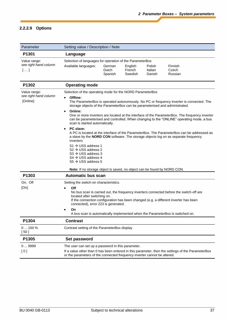
2.2.2.9 Options
Parameter Setting value / Description / Note
P1301 Language
Value range: see right hand column
[ … ]
Selection of languages for operation of the ParameterBox
Available languages: German English Polish Finnish Dutch French Italian Czech Spanish Swedish Danish Russian
P1302 Operating mode
Value range: see right hand column
[Online]
Selection of the operating mode for the NORD ParameterBox
Offline:
The ParameterBox is operated autonomously. No PC or frequency inverter is connected. The storage objects of the ParameterBox can be parameterised and administrated.
Online:
One or more inverters are located at the interface of the ParameterBox. The frequency inverter can be parameterised and controlled. When changing to the “ONLINE” operating mode, a bus scan is started automatically.
PC slave:
A PC is located at the interface of the ParameterBox. The ParameterBox can be addressed as a slave by the NORD CON software. The storage objects log on as separate frequency
inverters S1 USS address 1 S2 USS address 2 S3 USS address 3 S4 USS address 4 S5 USS address 5 Note: If no storage object is saved, no object can be found by NORD CON.
P1303 Automatic bus scan
On, Off
[On]
Setting the switch-on characteristics.
Off
No bus scan is carried out, the frequency inverters connected before the switch-off are located after switching on. If the connection configuration has been changed (e.g. a different inverter has been connected), error 223 is generated.
On
A bus scan is automatically implemented when the ParameterBox is switched on.
P1304 Contrast
0 ... 100 % [ 50 ]
Contrast setting of the ParameterBox display
P1305 Set password
0 ... 9999
[ 0 ]
The user can set up a password in this parameter.
If a value other than 0 has been entered in this parameter, then the settings of the ParameterBox or the parameters of the connected frequency inverter cannot be altered.

NORDAC Control and Parameter Boxes
38 Subject to technical alterations BU 0040 GB-0113
Parameter Setting value / Description / Note
P1306 Box password
0 ... 9999
[ 0 ]
If the password function is to be reset, the password selected in the >Set Password< parameter must be entered here. If the correct password has been selected, than all functions of the ParameterBox can be used again.
NOTE: In case the password is not known and parameterisation of the inverter needs to be
carried out, please contact our Technical Support.
P1307 Reset Box parameter
Start, Off
[Off]
In this parameter the ParameterBox can be reset to the default setting. All ParameterBox settings and the data in the storage media will be deleted.
P1308 NORDAC p-box
Version ... R …
[ … ]
Displays the software version of the ParameterBox. Please keep to hand.
2.2.3 Table of possible error messages
The following describes all possible error messages of the ParameterBox. Error messages which relate to the connected frequency inverter (E xx.x) are described in the frequency inverter manual or one of the relevant supplementary instructions.
Display
Error number
Fault
Text in the ParameterBox
Cause
Remedy
Communication error
200 Illegal parameter number
These error messages are due to EMC interference or differing software versions of the participants.
Check the software version of the ParameterBox and that of the connected frequency inverter.
Check the cabling of all components, regarding possible EMC interference
Plug-in EEPROM on the frequency inverter (Memory module) not recognised (Error: 201) Check for firm connection
201 Parameter value cannot be changed
202 Parameter value out of range
203 Faulty SUB Index
204 No Array parameter
205 Incorrect parameter type
206 Incorrect response identifier USS interface
207 Checksum error of USS interface
Communication between frequency inverter and ParameterBox is faulty (EMC), safe operation cannot be guaranteed.
Check the connection to the frequency inverter. Use a shielded cable between the devices. Route the BUS leads separately from the motor cables.
208 Incorrect status identifier USS interface
Communication between frequency inverter and ParameterBox is faulty (EMC), safe operation cannot be guaranteed.
Check the connection to the frequency inverter. Use a shielded cable between the devices. Route the BUS leads separately from the motor cables.
209 Inverter not responding The ParameterBox is waiting for a response from the connected frequency inverter. The waiting time has elapsed without a response being received.
Check the connection to the frequency inverter. The settings of the USS parameters for the frequency inverter were changed during operation.

2 Parameter Boxes – System parameters
BU 0040 GB-0113 Subject to technical alterations 39
Display
Error number
Fault
Text in the ParameterBox
Cause
Remedy
Identification errors
220 Unknown device Device ID not found. The connected inverter is not listed in the database of the ParameterBox; no communication can be established.
Please contact your Getriebebau Nord Representative.
221 Software version not recognised The software of the connected frequency inverter is not listed in the ParameterBox database, no communication can be set up.
Please contact your Getriebebau Nord Representative.
222 Inverter extension level not recognised An unknown module has been detected in the frequency inverter (Customer interface / Special extension).
Please check the modules installed in the frequency inverter
If necessary, check the software version of the ParameterBox and the frequency inverter.
223 Bus configuration has changed After restoring the last Bus configuration, a device is reported that is different from the one stored. This error can only occur if the parameter >Auto. Bus Scan< is set to OFF and another device has been connected to the ParameterBox.
Activate the automatic Bus scan function.
224 Device is not supported The inverter type entered in the ParameterBox is not supported!
The ParameterBox cannot be used with this frequency inverter.
225 The connection to the inverter is blocked
Access to a device that is not online (previous Time Out error).
Carry out a bus scan via the parameter >Bus Scan< (P1001).
ParameterBox operating error
226 Source and target are different devices
Copying objects of different types (from / to different inverters) is not possible.
227 Source is empty Copying of data from a deleted (empty) storage medium
228 This combination is not permitted Target and source for the copying function are the same. The command cannot be carried out.
229 Object selected is empty Parameterisation attempt of a deleted storage medium
230 Different software versions Warning Copying objects with different software versions can lead to problems when transferring parameters.
231 Invalid password Attempt to alter a parameter without a valid Box password being entered in parameter >Box Password< P 1306.
232 Bus scan only during operation: online A bus scan (search for a connected frequency inverter) is only possible when in ONLINE mode.

NORDAC Control and Parameter Boxes
40 Subject to technical alterations BU 0040 GB-0113
Display
Error number
Fault
Text in the ParameterBox
Cause
Remedy
Warnings
240 Overwrite data?
→ Yes No
These warnings indicate that there is a possibly significant change which needs additional confirmation.
Once the next procedure has been selected, it must be confirmed with the "ENTER" key.
241 Delete data?
→ Yes No
242 Different SW version?
→ Next Cancel
243 Different series?
→ Next Cancel
244 Delete all data?
→ Yes No
Inverter control error
250 This function is not enabled The function requested is not enabled at the frequency inverter parameter interface.
Change the value of the parameter >Interface< of the connected inverter to the required function. More detailed information can be obtained from the operating instructions for the frequency inverter.
251 Control command was not successful The control command cannot be implemented by the frequency inverter, as a higher priority function, e.g. Quick stop or an OFF signal to the control terminals of the frequency inverter is present.
252 Control is not possible offline Call up of a control function in Offline mode.
Change the operating mode of the ParameterBox in the parameter >Operating Mode< P1302 to Online and repeat the action.
253 Error acknowledgement not successful The acknowledgement of an error at the frequency inverter was not successful, the error message remains in effect.
Error message from inverter
Inverter error number
Inverter error text A fault has occurred in the inverter with the number displayed. The inverter error number and text are displayed.
2.3 Technical data
Name SK TU3-PAR SK PAR-2H SK PAR-2E SK PAR-3H SK PAR-3E SK CSX-3H SK CSX-3E SK TU3-CTR
Control voltage 4.5VDC … 30VDC
Power consumption
approx. 1.3 W approx. 1.3 W approx. 1.3 W approx. 1.3 W approx. 1.3 W approx. 1.0 W approx. 1.0 W approx. 1.0 W
Display Plain text display 4-digit, 7-segment display
Interfaces SPI-Bus RS485 RS485 RS485 and RS485 RS485 RS485 SPI-Bus
Ambient temperature
0°C … 40°C
Protection class IP20 IP541) IP54
2) IP54
3) IP54
2) IP54
3) IP54
2) IP20
Dimensions (L x W x D)
(73 x 100 x 20) mm
(90 x 145 x 27) mm
(100 x 162 x 38) mm
(117 x 73 x 24) mm
(128 x 83 x 32) mm
(117 x 73 x 24) mm
(128 x 83 x 32) mm
(73 x 100 x 20) mm
Weight approx. 0,2 kg 0.7 kg 0.5 kg 0.2 kg 0.6 kg 0.2 kg 0.6 kg 0,2 kg
Connection cable length
Not possible approx. 3m approx. 2m approx. 2m Not possible
1) with plug inserted
2) on the front side
3) on plug socket IP20

2 Parameter Boxes – Accessories
BU 0040 GB-0113 Subject to technical alterations 41
2.4 Accessories for NORD parameterisation boxes (except SK TU3-xxx)
2.4.1 SK IC1-232/485 interface converter
The SK IC1-232/485 interface converter converts signals from RS485 to RS232. This converter is used for connecting a PC or a laptop to a NORD frequency inverter (RS485) or to a series PAR-2x ParameterBox.
With the aid of the NORD CON software the frequency inverter or the
ParameterBox can be controlled and parameterised. In addition, the software provides a convenient diagnostic tool with an oscilloscope function in order to enable the optimisation of drive solutions. (SK IC1-232/485, Part No. 276970020) Note: An adapter can be supplied for the power supply (5V/250mA) from the PC USB port to the converter. Please make sure that the USB port is suitable for high power devices. A connected ParameterBox is also supplied via this 5V.
2.4.2 Cable-Adapter assignment
The following table shows the necessary adapters for use with the various parameter boxes. The assignment of the adapters to individual inverter series and the parameter boxes to be used can be obtained from the other table in this section.
2.4.2.1 Adapter list
Serial No. Illustration Name Article number
1
“Modular cable
Straight RJ12 (6/6) - RJ12 (6/6) cable”
Not a NORD item
generally available
2
“Connection cable M12 socket RJ12”
Part No.: 278910230
3
“Connection cable
M12 plug RJ12” SK TIE4-M12-RJ12
Part No.: 275274600
4
“Connection cable
M12 socket free leads”
Part No.: 278910200
5
“Connection cable SUB-D 9 free leads”
Part No.: 278910020
6
“Connection cable
M12 socket SUB-D 9”
Part No.: 278910210
7
“Connection cable
USB2.0 plug A to plug B”
Not a NORD item
generally available
8
Interface converter
“SK IC1-232/485”
Part No.: 276970020
9
„Connection cable USB/5V SK IC1-232/485“
Part No.: 278910220
RS 485 +RS 485 -GND
+ 5V
n.c.n.c.
RS 485 +RS 485 -GND
+ 5V
n.c.n.c.
RS 485 +
RS 485 -
GND+ 5V
RS 485 +
RS 485 -
GND
+ 5V/+15V

NORDAC Control and Parameter Boxes
42 Subject to technical alterations BU 0040 GB-0113
2.4.2.2 Assignment of parameterisation box - frequency inverter
ParameterBox ParameterBox SimpleBox
SK PAR-2E
SK PAR-2H
SK PAR-3H
SK PAR-3E SK CSX-3H
SK CSX-3E
Frequency inverter Interface RS485 RS485 RS485 / USB RS485 RS485 SK 200E
1* 2* 1 1 1
SK TI4-TU-BUS (BUS connection unit)
1 2 1 1 Not possible
SK 300E
Wiring to connection terminals,
4-lead
Direct connection with system
plug
3 3 Not possible
SK 500E
1 2 1 1 1
SK 700E >22KW or with option -RS2
1** 2** 1** 1** 1**
SK 700E with customer interface SK CU1-STD
+
Wiring to connection terminals,
4-lead
4 3 + 4 3 + 4 3 + 4
SK 750E
Not possible
Direct connection with system
plug
3 3 3
SK 750E with customer interface SK CU1-STD
+
Wiring to connection terminals,
4-lead
Direct connection with system
plug
3 3 3
Vector mc
Wiring to connection terminals,
4-lead
4 Not possible Not possible Not possible
Nord Con
5 + 8 + 9 6 + 8 + 9 7 Not possible Not possible
* The ParameterBox series SK PAR-2x can only access the SK 200E after a modification to the hardware. The launch of the modified ParameterBox series was in the 4th quarter of 2009. ** SK 700E < 30KW: safe operation is only ensured with an external power supply to the ParameterBoxes.
Further details of the SK PAR 2H can be found in Section 2.1.1.2 Connection variants

3 ControlBoxes – SK POT1-1
BU 0040 GB-0113 Subject to technical alterations 43
3 ControlBoxes
With the aid of ControlBoxes it is possible to control a frequency inverter with regard to speed and direction of rotation.
3.1 SK SSX-3A – Simple Setpoint Box
The "Simple Set Point Box" SK SSX-3A is a compact control unit with a 4-digit, 7-segment display, which is primarily intended for fixed connection to the terminal bar of the frequency inverter. The control unit can be used as a handheld or attached version (wall-mounted). A maximum cable length of 20m must be observed. Three operating modes are available, which are automatically activated according to the connection variant and the inverter series. The entire range of functions can be used with the SK 2xxE series. If an RS 485 interface is available, the box can also be used with SK 300E, SK 5xxE, SK 700E and SK 750E inverters. However, in this case only the 485C mode (control mode via RS 485) is available.
3.1.1 Installation
The box can be opened by opening the screw fastenings at the front. The connection terminals for the electrical connections and a 2-part DIP switch element are located inside the box on the rear side of the cover. In addition to an M12 cable gland, the other section of the housing contains 2 holes for optional wall mounting. Mounting on an SK 2xxE frequency inverter An adapter kit is available for the direct mounting of the SK SSX-3A onto an SK 2xxE series frequency inverter.
Designation: SK TIE4-SSX-3A-adapter kit
Part No.: 275274910
Scope of supply:
1x Mounting plate 1x M16 x1.5 cable gland
4x SW7-M4 spacer bolts
4x M4 x 8 countersink screw 2x M4 x 8 cylindrical-head screw
1x SK 200E connection cable SSX_3A
Illustration: Installation material, without connection cable and cable gland.
Holes for wall mounting

NORDAC Control and Parameter Boxes
44 Subject to technical alterations BU 0040 GB-0113
The SK 2xxE is installed with the following steps:
Step Description Illustration
1 Screw in the four hexagon-head spacer bolts into the four threaded holes of the frequency inverter connection unit, which are used to mount an SK TU4-xxx.
2 Fasten the mounting plate onto the spacer bolts with the countersink screws.
NB: The countersink must be on the upper surface, so that the countersink screws are flush with the surface after fitting..
3 Fasten the base housing of the SK SSX-3A to the mounting plate with two cylindrical-head screws and lead the connecting cable from the SK SSX-3A to the connection unit of the frequency inverter.
Recommendation: Insert the cable via the bottom M16 opening using the enclosed cable gland.
4 Make the connections (see Section 3.1.2 and 3.1.3 )
Place the SK SSX-3A on the base housing and close it with the four screws.
3.1.2 Connection
The Simple Setpoint Box provides various operating modes. The connection of the data or supply cables must be made in different ways, depending on the required operating mode. Connection is made to the terminal bar by means of a 3 or 4 wire cable. For a description of the terminal connections, please refer to Section 3.1.3 . Connection data:
Name Value
Rigid cable cross-section 0.14 … 2.5mm²
Flexible cable cross-section 0.14 … 1.5mm²
AWG standard AWG 26-14
Tightening torque for screw terminals
0.5…0.6Nm
The connection cable must be fed out of the device via a cable gland (supplied). The cable gland must be screwed into the rear section of the housing. It is recommended that the length of the connection cable is limited to 20 m. The cable should be laid separately from other cables to avoid interference.
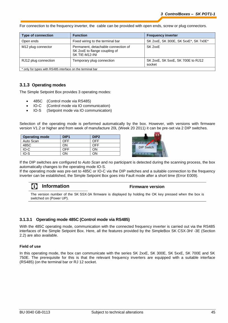
3 ControlBoxes – SK POT1-1
BU 0040 GB-0113 Subject to technical alterations 45
For connection to the frequency inverter, the cable can be provided with open ends, screw or plug connectors.
Type of connection Function Frequency inverter
Open ends Fixed wiring to the terminal bar SK 2xxE, SK 300E, SK 5xxE*, SK 7x0E*
M12 plug connector Permanent, detachable connection of SK 2xxE to flange coupling of SK TIE-M12-INI
SK 2xxE
RJ12 plug connection Temporary plug connection SK 2xxE, SK 5xxE, SK 700E to RJ12 socket
* only for types with RS485 interface on the terminal bar
3.1.3 Operating modes
The Simple Setpoint Box provides 3 operating modes:
485C (Control mode via RS485)
IO-C (Control mode via IO communication)
IO-S (Setpoint mode via IO communication)
Selection of the operating mode is performed automatically by the box. However, with versions with firmware version V1.2 or higher and from week of manufacture 20L (Week 20 2011) it can be pre-set via 2 DIP switches.
Operating mode DIP1 DIP2 Auto Scan OFF OFF 485C ON OFF IO-C OFF ON IO-S ON ON
If the DIP switches are configured to Auto Scan and no participant is detected during the scanning process, the box automatically changes to the operating mode IO-S. If the operating mode was pre-set to 485C or IO-C via the DIP switches and a suitable connection to the frequency inverter can be established, the Simple Setpoint Box goes into Fault mode after a short time (Error E009).
Information Firmware version
The version number of the SK SSX-3A firmware is displayed by holding the OK key pressed when the box is switched on (Power UP).
3.1.3.1 Operating mode 485C (Control mode via RS485)
With the 485C operating mode, communication with the connected frequency inverter is carried out via the RS485 interfaces of the Simple Setpoint Box. Here, all the features provided by the SimpleBox SK CSX-3H/ -3E (Section 2.2) are also available.
Field of use
In this operating mode, the box can communicate with the series SK 2xxE, SK 300E, SK 5xxE, SK 700E and SK 750E. The prerequisite for this is that the relevant frequency inverters are equipped with a suitable interface (RS485) (on the terminal bar or RJ 12 socket.
DIP Switch
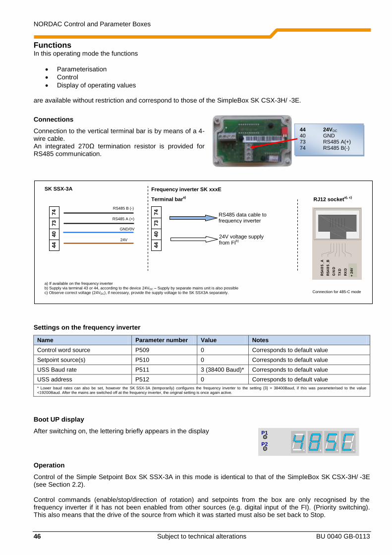
NORDAC Control and Parameter Boxes
46 Subject to technical alterations BU 0040 GB-0113
P1
P2
Functions In this operating mode the functions
Parameterisation
Control
Display of operating values are available without restriction and correspond to those of the SimpleBox SK CSX-3H/ -3E.
Connections
Connection to the vertical terminal bar is by means of a 4-wire cable. An integrated 270Ω termination resistor is provided for RS485 communication.
Settings on the frequency inverter
Name Parameter number Value Notes
Control word source P509 0 Corresponds to default value
Setpoint source(s) P510 0 Corresponds to default value
USS Baud rate P511 3 (38400 Baud)* Corresponds to default value
USS address P512 0 Corresponds to default value * Lower baud rates can also be set, however the SK SSX-3A (temporarily) configures the frequency inverter to the setting 3 = 38400Baud, if this was parameterised to the value <19200Baud. After the mains are switched off at the frequency inverter, the original setting is once again active.
Boot UP display
After switching on, the lettering briefly appears in the display
Operation
Control of the Simple Setpoint Box SK SSX-3A in this mode is identical to that of the SimpleBox SK CSX-3H/ -3E (see Section 2.2). Control commands (enable/stop/direction of rotation) and setpoints from the box are only recognised by the frequency inverter if it has not been enabled from other sources (e.g. digital input of the FI). (Priority switching). This also means that the drive of the source from which it was started must also be set back to Stop.
Terminal bara)
24V
GND/0V
44
40
73
74
24V voltage supply from FI
b)
RS485 data cable to frequency inverter
RS485 B (-)
RS485 A (+)
SK SSX-3A Frequency inverter SK xxxE
44
40
73
74
VR
EF
10
V
AG
ND
0V
AIN
1+
AIN
2+
AO
UT
1
DIG
IN
1
DIG
IN
2
DIG
IN
3
DIG
IN
4
VO
+1
5V
DG
ND
0V
11
12
13
14
16
22
23
24
25
42
40
21
DIG
IN
5
1 2 3 4R
EL
2.2
RE
L 2
.1
RE
L1
.2
RE
L 1
.1
CA
N_
H
CA
N_
L
CA
N_
GN
D
nc
CA
N_
SH
LD
CA
N_
GN
D
nc
CA
N_
24
V
CA
N_
H
CA
N_
L
CA
N_
GN
D
nc
CA
N_
SH
LD
CA
N_
GN
D
nc
CA
N_
24
V
RS
48
5_
A
RS
48
5_
B
GN
D
TX
D
RX
D
41
VO
+5
V
+5
V
+ 2
4V
RJ12 socketa), c)
Connection for 485-C mode
a) If available on the frequency inverter b) Supply via terminal 43 or 44, according to the device 24VDC – Supply by separate mains unit is also possible c) Observe correct voltage (24VDC), if necessary, provide the supply voltage to the SK SSX3A separately.
44 24VDC 40 GND 73 RS485 A(+) 74 RS485 B(-)

3 ControlBoxes – SK POT1-1
BU 0040 GB-0113 Subject to technical alterations 47
The setpoint value from the Simple Setpoint Box is only processed as a master setpoint. However, as usual, setpoints from other sources can be taken into account in the form of auxiliary setpoints (e.g. frequency addition).
ATTENTION The drive unit does not stop automatically
If the SK SSX-3A is disconnected from an enabled frequency inverter, the drive will continue to run. In order to stop the drive, the SK SSX-3A must be reconnected to the frequency inverter.
The parameter (P513) "Telegram timeout" can be set in order to monitor communication.
Interruption of communication
An interruption of communication (disconnection of the plug, individual cables) has various effects on the frequency inverter and the Simple Setpoint Box.
Disconnection of one or both data cables (RS485)
The error E009 appears in the box display. The frequency inverter does not react and maintains its operating condition. If the frequency inverter was started with the SK SSX-3A, it must also be stopped with the SK SSX-3A. As an alternative, it is also possible to stop it with the SimpleBox (SK CSX-3x), NORD CON or the ParameterBox in ControlBox mode. The parameter (P513) "Telegram timeout" provides an optional monitoring of communication on the inverter side. If the communication cannot be restored after interruption within the time set, the drive is stopped without an error message. If the data connection is restored, the SK SK SSX-3A starts a scan process and switches online again immediately after this is completed. The error message is no longer displayed.
Loss of supply voltage
Except for the fact that the Simple Setpoint Box switches off without an error message, the box and the frequency inverter behave identically with regard to the behaviour described above under "Disconnection of data cables".
3.1.3.2 Operating mode IO-C (Control mode via DI1/DO1 of the SK 2xxE)
In the operating mode IO-C, communication is via digital input "1" and digital output "1" of the frequency inverter. Here, all the features provided by the SimpleBox SK CSX-3H/ -3E (Section 2.2) are also available.
Field of use
In this operating mode, the box can communicate with SK 2xxE series frequency inverters with firmware version V 1.3 or higher (see parameter (P707[-01])).
Functions
In this operating mode the functions
Parameterisation
Control
Display of operating values are available without restriction and correspond to those of the SimpleBox SK CSX-3H/ -3E. For technical reasons, the display and the key reaction times are somewhat increased.

NORDAC Control and Parameter Boxes
48 Subject to technical alterations BU 0040 GB-0113
P1
P2
Connections
Connection to the horizontal terminal bar is by means of a 4-wire cable.
Settings on the frequency inverter
Name Parameter number Value Notes
Function, digital output 1 P434 [-01] 00 or 07* Setting 07 corresponds to the default value * Other settings are not permissible and result in the loss of communication between the Simple Setpoint Box and the frequency inverter in IO-C mode.
Information Deactivation of the IO functions
In "IO-C" mode, the parameterised functions of the IOs "Digital Input 1 (parameter (P420[-01])) and "Digital Output 1" (parameter (P434[-01])) are deactivated. The condition for this is that Digital Output 1 is parameterised either to "No function" 00 or the default setting "Fault" 07.
The DIP switch S1: 3 … 5 of the frequency inverter ("BUS" / "IO") must be left in the factory setting ("OFF" or"0") in order to prevent communication faults on the frequency inverter.
Information Parameter P434[-01] – Disabling the IO-C mode
If the parameter (P434[-01]) is set to values ≠ 00 or ≠ 07, the IO-C mode of the SK SSX-3A is barred when the frequency inverter restarts.
Boot UP display
After switching on, the lettering briefly appears in the display
Operation
Control of the Simple Setpoint Box SK SSX-3A in this mode is identical to that of the SimpleBox SK CSX-3H/ -3E (see Section 2.2). Control commands (enable/stop/direction of rotation) and setpoints from the box are only recognised by the frequency inverter if it has not been enabled from other sources (e.g. digital input of the FI) (priority switching). This also means that the drive of the source from which it was started must also be set back to Stop.
24V
GND/0V
44
40
B1
C1
24V voltage supply from SK 2xxEb)
I/O connection for FI setpoint values
IN
OUT
Connection for IO-C mode
SK SSX-3A SK 2xxE-
44
40
21
1
I/O connection for actual FI values
a) If available on the frequency inverter b) Supply via terminal 43 or 44, according to the device 24VDC – Supply by separate mains unit is also possible c) Observe correct voltage (24VDC), if necessary, provide the supply voltage to the SK SSX3A separately.
44 24VDC 40 GND B1 Signal OUT C1 Signal IN
3 ControlBoxes – SK POT1-1
BU 0040 GB-0113 Subject to technical alterations 49
The setpoint value from the Simple Setpoint Box is only processed as a master setpoint. However, as usual, setpoints from other sources can be taken into account in the form of auxiliary setpoints (e.g. frequency addition).
ATTENTION The drive unit does not stop automatically
If the SK SSX-3A is disconnected from an enabled frequency inverter, the drive will continue to run. In order to stop the drive, the SK SSX-3A must be reconnected to the frequency inverter. The parameter (P513) "Telegram timeout" can be set in order to monitor communication.
Information Timeout monitoring (P513)
With the use of the timeout function (P513) settings >6s should be avoided. Otherwise, if only the actual value channel (Terminal C1 to Terminal 1) is interrupted, monitoring does not function.
Interruption of communication
An interruption of communication (disconnection of the plug, individual cables) has various effects on the frequency inverter and the Simple Setpoint Box.
Disconnection of the actual value channel (Connection Terminal C1 (SK SSX-3A) to Terminal 1 (SK 2xxE))
The error E009 appears in the box display after a delay. The frequency inverter does not react and maintains its operating condition. If the frequency inverter was started with the SK SSX-3A, it must also be stopped with the SK SSX-3A. As an alternative, it is also possible to stop it with the SimpleBox (SK CSX-3x), NORD CON or the ParameterBox in ControlBox mode. The parameter (P513) "Telegram timeout" provides an optional monitoring of communication on the inverter side. If the communication cannot be restored after interruption within the time set (max. 6 sec) the drive is stopped with the error message E010 (10.0). If the data connection is restored, the SK SSX-3A starts a scan process and switches online again immediately after this is completed. The error messages are no longer displayed.
Disconnection of the setpoint value channel (Connection Terminal B1 (SK SSX-3A) to Terminal 21 (SK 2xxE))
The error E009 appears in the box display after a delay. The frequency inverter does not react and maintains its operating condition. If the frequency inverter was started with the SK SSX-3A, it must also be stopped with the SK SSX-3A. As an alternative, it is also possible to stop it with the SimpleBox (SK CSX-3x), NORD CON or the ParameterBox in ControlBox mode. The parameter (P513) "Telegram timeout" provides an optional monitoring of communication on the inverter side. If the communication cannot be restored after interruption within the time set (max. 6 sec) the drive is stopped with the error message E010 (10.0). If the data connection is restored, the SK SK SSX-3A starts a scan process and switches online again immediately after this is completed. The error messages are no longer displayed.
Loss of supply voltage
Except for the fact that the Simple Setpoint Box switches off without an error message, the box and the frequency inverter behave identically with regard to the behaviour described above under "Disconnection of the setpoint channel".
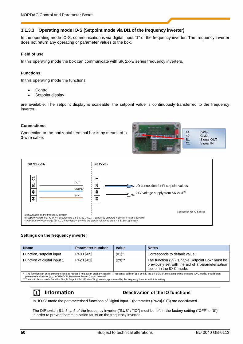
NORDAC Control and Parameter Boxes
50 Subject to technical alterations BU 0040 GB-0113
3.1.3.3 Operating mode IO-S (Setpoint mode via DI1 of the frequency inverter)
In the operating mode IO-S, communication is via digital input "1" of the frequency inverter. The frequency inverter does not return any operating or parameter values to the box.
Field of use
In this operating mode the box can communicate with SK 2xxE series frequency inverters.
Functions
In this operating mode the functions
Control
Setpoint display are available. The setpoint display is scaleable, the setpoint value is continuously transferred to the frequency inverter.
Connections
Connection to the horizontal terminal bar is by means of a 3-wire cable.
Settings on the frequency inverter
Name Parameter number Value Notes
Function, setpoint input P400 [-05] 01* Corresponds to default value
Function of digital input 1 P420 [-01] 29** The function 29 "Enable Setpoint Box" must be previously set with the aid of a parameterisation tool or in the IO-C mode.
* The function can be re-parameterised as required (e.g. as an auxiliary setpoint ("Frequency addition")). For this, the SK SSX-3A must temporarily be set to IO-C mode, or a different parameterisation tool (e.g. NORD CON, ParameterBox etc.) must be used.
** The control commands from the Simple Setpoint Box (Enable/Stop) are only processed by the frequency inverter with this setting.
Information Deactivation of the IO functions
In "IO-S" mode the parameterised functions of Digital Input 1 (parameter (P420[-01])) are deactivated.
The DIP switch S1: 3 … 5 of the frequency inverter ("BUS" / "IO") must be left in the factory setting ("OFF" or"0") in order to prevent communication faults on the frequency inverter.
24V
GND/0V
44
40
B1
C1
24V voltage supply from SK 2xxEb)
I/O connection for FI setpoint values OUT
Connection for IO-S mode
SK SSX-3A SK 2xxE-
44
40
21
1
a) If available on the frequency inverter b) Supply via terminal 43 or 44, according to the device 24VDC – Supply by separate mains unit is also possible
c) Observe correct voltage (24VDC), if necessary, provide the supply voltage to the SK SSX3A separately.
44 24VDC 40 GND B1 Signal OUT C1 Signal IN

3 ControlBoxes – SK POT1-1
BU 0040 GB-0113 Subject to technical alterations 51
P1
P2
Boot UP display
After switching on, the lettering briefly appears in the display
Operation
Control of the Simple Setpoint Box SK SSX-3A in this mode is the same as that of the SimpleBox SK CSX-3H/ -3E (see Section 2.2), however with the following differences:
No access to frequency inverter parameters is possible.
The display does not show the actual operating value of the frequency inverter, but rather the setpoint value transferred from the SK SSX-3A.
The setpoint is displayed as a percentage (-100.0% … 0.0 … 100.0%) and is scaleable (P050).
Pressing the "OK" key during operation does not save the displayed value as the "jog frequency" of the frequency inverter (P113), but rather as the "Starting value" within the box (P051).
Control commands (Enable/Stop/Direction of rotation) from the box are processed additively by the frequency inverter. An enable command from the box corresponds to an "Enable right". If, for example, the frequency inverter is enabled by the box and also receives a parallel enable command ("Enable left") via a digital input, the two enable commands cancel each other out. The drive runs down its braking ramp to speed "0" and switches to the state "Ready for switch-on". Processing of setpoint values is carried out according to the settings in parameter (P400[-05]). In the factory setting of the parameter, the setpoint value of the SK SSX-3A has the properties of a master setpoint value. If setpoint values from other sources are to be taken into account, these must be defined as auxiliary setpoints. Example
Frequency inverter SK 2x5E-...
Con
tro
l te
rmin
al ba
r
44
40
.
.
21
22
23
24
.
.
.
SK SSX-3A
Potentio-meter
0-10
L1 - L2/N - L3 115/230/400V
24V mains unit SK CU4-24V-...
L1 - L2/N 115/230/400V
24V=
GND
10V=
AGND
0-10V IO-Link
0-100%
1/3~ 115/230/400V + PE
Control terminal bar
44 40 44 ... 11 14 12 B1
(br)
(bl)
(br) (wh) (bl)
C1 B1 40 44 Control terminal bar
In addition to the Simple Setpoint Box, a potentiometer is connected to an SK 2x5E type frequency inverter. Its analog signal is converted into pulses in the SK CU4-24V…mains unit and passed to Digital Input 3 of the frequency inverter. After conversion of the function of Digital Input 3 (P420 [-03]) to the function 26 "Analog

NORDAC Control and Parameter Boxes
52 Subject to technical alterations BU 0040 GB-0113
function", the parameter (P400 [-07])must be parameterised to 02 "Frequency addition". In this configuration, the analog signal is processed additively to the setpoint value of the SK SSX-3A.
Information Display
The display on the SK SSX-3A does not provide any information about the actual speed of the drive. Only the currently set setpoint value of the Simple Setpoint Box is displayed.
Parameterisation
The Simple Setpoint Box has its own parameters. The parameters can only be accessed if the SK SSX-3A is in IO-S mode and is not currently sending an enable signal.
As with the SimpleBox (see Section 2.2), the parameters are selected by pressing the VALUE keys or . By confirming with the "OK" key, the actual setting becomes visible and can be changed with the VALUE keys. New
values are adopted and permanently stored in the SK SSX-3A by pressing the "OK" key again. With the keys or
the display returns to the initial display or one level backwards. Changes which have not been confirmed with "OK" are not saved. During parameterisation the two LEDs of the SK SSX-3A (P1 and P2) illuminate continuously.
Parameter Setting value / Description / Note
P050 Scaling factor
0.01 … 99.99
[ 1.00 ]
With this parameter, the scaling of the SK SSX-3A display in IO-S mode can be changed. It is therefore possible to display system-specific operating such as e.g. the throughput quantity.
The setting 1.00 corresponds to a displayed value from -100% to 100%.
Note: Only values which are sent by the SK SSX-3A are taken into account in the
display.
P051 Starting value
(-100 ... 100)x(P050)
[ 0.0 ]
Storage of the starting value.
The value set here is used as the starting value for the frequency inverter when it is enabled.
The starting value is not stored in the frequency inverter.
The starting value can also be written into the parameter from the currently set setpoint value of the box by pressing the "OK" key.
The value range of the starting value depends on the scaling (P050).
From a starting value < -999 (possible with scaling factors ≥ 10.00) the prefix is no longer displayed.
Interruption of communication
An interruption of communication (disconnection of the plug, individual cables) has various effects on the frequency inverter and the Simple Setpoint Box.
Disconnection of the setpoint value channel (Connection Terminal B1 (SK SSX-3A) to Terminal 21 (SK 2xxE))
The Simple Setpoint Box does not report an error and remains in operation. Setpoints and enabling can be changed on it. On the other hand, the drive is stopped unless it is provided with an enable signal and a setpoint value from another source. The parameter (P513) "Telegram timeout" provides an optional monitoring of communication on the inverter side. If the communication cannot be restored after interruption within the time set (max. 6 sec) the drive is stopped with the error message E010 (10.0).
If the data connection is restored, the error must first be acknowledged (sequential pressing of the and keys) in order to restart the drive.

3 ControlBoxes – SK POT1-1
BU 0040 GB-0113 Subject to technical alterations 53
Loss of supply voltage
Except for the fact that the Simple Setpoint Box switches off without an error message, the box and the frequency inverter behave identically with regard to the behaviour described above under "Disconnection of the setpoint channel".
3.1.4 Technical data
Name Value
Control voltage 24VDC ± 20%
Power consumption approx. 35 mA
Display 4-digit, 7-segment display
Interfaces RS232 or RS485
Operating modes 485C / IO-C / IO-S
Ambient temperature 0°C … 40°C
Protection class IP54
Dimensions (L x W x D) (98 x 64 x 37)mm
Weight 0.3 kg
Wall-mounting possible with 2 holes at the rear
Connection cable length max. 20 m (not included in scope of delivery)
3.2 Control box (SK POT1-1)
The SK POT1-1 control box is a simple manual control unit for the control of NORD frequency inverters with an enabling signal and setpoint. The control box is designed for permanent connection to the frequency inverter. According to the model, appropriate interfaces are available on the frequency inverter, or are available as options. Further information about the interfaces can be found in the relevant manual for the frequency inverter. The control unit can be used as a handheld or attached version (wall-mounted). An approx. 3m long cable is included.
3.2.1 Installation
The SK POT1-1 control box is a hand-held unit with integrated connection cable. The connection cable has open ends and is intended for permanent connection to a NORD frequency inverter. The control box can also be screwed to a wall via the four holes in the rear of the housing (Distance approx: X direction: 106.5mm, Y direction: 66.5mm). The fixing material is not included in the scope of delivery.
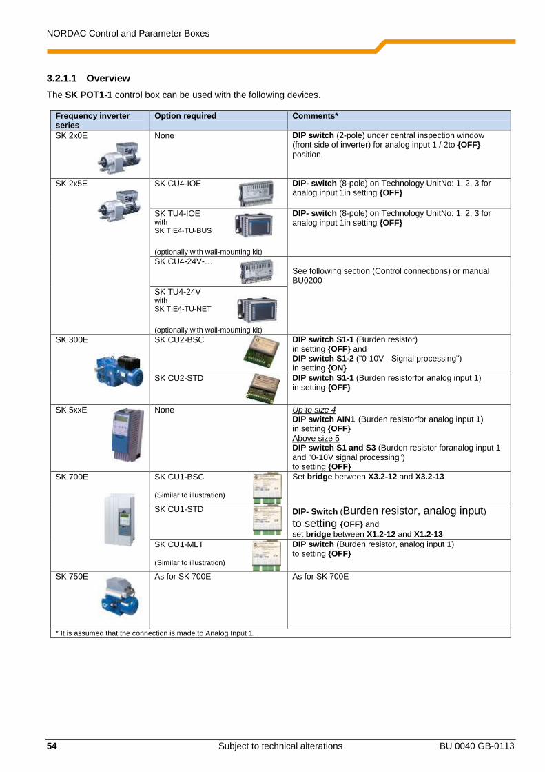
NORDAC Control and Parameter Boxes
54 Subject to technical alterations BU 0040 GB-0113
3.2.1.1 Overview
The SK POT1-1 control box can be used with the following devices.
Frequency inverter series
Option required Comments*
SK 2x0E
None DIP switch (2-pole) under central inspection window (front side of inverter) for analog input 1 / 2to OFF
position.
SK 2x5E
SK CU4-IOE
DIP- switch (8-pole) on Technology UnitNo: 1, 2, 3 for analog input 1in setting OFF
SK TU4-IOE with SK TIE4-TU-BUS
(optionally with wall-mounting kit)
DIP- switch (8-pole) on Technology UnitNo: 1, 2, 3 for analog input 1in setting OFF
SK CU4-24V-…
See following section (Control connections) or manual BU0200
SK TU4-24V with SK TIE4-TU-NET
(optionally with wall-mounting kit)
SK 300E SK CU2-BSC
DIP switch S1-1 (Burden resistor) in setting OFF and DIP switch S1-2 ("0-10V - Signal processing") in setting ON
SK CU2-STD
DIP switch S1-1 (Burden resistorfor analog input 1) in setting OFF
SK 5xxE None Up to size 4 DIP switch AIN1 (Burden resistorfor analog input 1) in setting OFF
Above size 5 DIP switch S1 and S3 (Burden resistor foranalog input 1
and "0-10V signal processing") to setting OFF
SK 700E SK CU1-BSC (Similar to illustration)
Set bridge between X3.2-12 and X3.2-13
SK CU1-STD
DIP- Switch (Burden resistor, analog input) to setting OFF and
set bridge between X1.2-12 and X1.2-13 SK CU1-MLT (Similar to illustration)
DIP switch (Burden resistor, analog input 1) to setting OFF
SK 750E
As for SK 700E As for SK 700E
* It is assumed that the connection is made to Analog Input 1.

3 ControlBoxes – SK POT1-1
BU 0040 GB-0113 Subject to technical alterations 55
3.2.1.2 Control connections
Illustration of the function of the SK POT1-1 control box
Connections are made according to the following table:
Frequency inverter series
SK 2x0E2) SK 2x5E
3) SK 300E SK 5xxE SK 700E or SK 750E
Interface option SK POT1-1 Terminal - Colour
No Terminal (Function)
SK CU4-IOE / SK TU4-IOE Terminal (Function)
SK CU2-BSC / SK CU2-STD Terminal (Function)
No Terminal (Function)
SK CU1 BSC / SK CU1-STD / SK CU1-MLT Terminal (Function)
1 - white 44 (+24V)
SK CU4-IOE
44 (+24V) or SK TU4-IOE
11 (+24V)
J2:42 (+15V) X5:42 (+15V /
+24V)
Xx.3:42 (+15V)
2 - brown 21 (DIN1) SK CU4-IOE
C1 (DIN5 (corresponds
to DIN1 of the box)) or SK TU4-IOE
19 (DIN5 (corresponds
to DIN1 of the box))
J2:22 (DIN2) X5:21 (DIN1) Xx.3:21 (DIN1)
3 - green 22 (DIN2) SK CU4-IOE
C2 (DIN6 (corresponds
to DIN2 of the box)) or SK TU4-IOE
25 (DIN6 (corresponds
to DIN2 of the box))
J2:23 (DIN3) X5:22 (DIN2) Xx.3:22 (DIN2)
4 - yellow 12 (AGND) SK CU4-IOE1)
13 (AIN1-)+12 (0V)) or SK CU4-IOE
1)
5 (AIN1-)+7 (0V))
SK CU2-STD
J2.2:12 (AGND) or SK CU2-BSC
1)
J2.13 (AIN-)+ J2.12 (AGND))
X4:12 (AGND) SK CU1-MLT
X2.2:12 (AGND) or SK CU1-BSC / -SDT)
1)
Xx.13 (AIN1-)+ Xx.12 (AGND))
5 - grey 14 (AIN1+) SK CU4-IOE
14 (AIN1+) or SK TU4-IOE
3 (AIN1+)
J2:14 (AIN1) X4:14 (AIN1) Xx.2:14 (AIN1)
6 - pink 11 (+ 10V) SK CU4-IOE
11 (+10V) or SK TU4-IOE
1 (+10V)
J2:11 (+10V) X4:11 (+10V) Xx.2:11 (+10V)
1) On the Technology Units of the SK 2xxE and on the basic I/O of the SK 300E and the basic I/O and standard I/O of the SK 700 / SK 750E, the analog inputs are implemented as differential inputs. In order to ensure the correct functioning of the potentiometer, the analog input "AIN-" must be connected with the analog ground.
2) For devices with an AS interface (SK 220E and SK 230E) Analog Inputs 2 (Terminal 16), and instead of AGND (Terminal 12), Terminal 14 (GND) must be used. In addition, the function of Analog Input 2 (P400[-02]) must be parameterised to the setting 01 = "Setpoint frequency".
3) Connection of SK POT1-1 to an SK 2x5E can alternatively by made to an IO extension module (SK xU4-IOE) via a suitable mains unit (SK xU4-24V-…). The connection is made according to the following pattern.

NORDAC Control and Parameter Boxes
56 Subject to technical alterations BU 0040 GB-0113
In combination with the SK CU4-24V-… or SK TU4-24V-… modules instead of the SK CU4-IOE or SK TU4-IOE Technology Units, the connection to an SK 2x5E series frequency inverter can, for example, be implemented according to the following pattern. (Note: Terminal 43 of the SK TU4-24V-… corresponds to Terminal 44 of the SK CU4-24V-…) Connection diagram for SK xU4-24V-… and parameterisation, example
Frequency inverter SK 205E-.../SK 215E-...
Con
tro
l te
rmin
al ba
r
44
40
.
.
21
22
23
24
.
.
.
L1 - L2/N - L3 115/230/400V
24V mains unit SK TU4-24V-... (+ SK TI4-TU-NET)*
or
SK CU4-24V-...
L1 - L2/N 115/230/400V
24V=
GND
10V=
AGND
0-10V R
L
0-100%
1/3~ 115/230/400V + PE
Control terminal bar
44* 40 44* ... 11 14 12 B1
Switch
Potentiometer 10kOhm
SK POT1-1
green
brown
white pink
green
yellow
DIP switch settings: DIP3 = off, DIP4 = on, DIP5 = off (Therefore no further parameterisation is necessary) or recommended parameter setting, DIP1-8 = off: P400 [07] = 1 P420 [02] = 2 P420 [01] = 1 P420 [03] = 26

3 ControlBoxes – SK POT1-1
BU 0040 GB-0113 Subject to technical alterations 57
3.2.2 Parameterisation
For the functions of the control box SK POT1-1, some parameters must be changed, according to the frequency inverter and the options. The most important of these are listed below. For further information, please refer to the manual for the relevant frequency inverter. Frequency inverter SK 2x0E
1) SK 2x5E: SK 300E SK 5xxE SK 700E SK 750E
+ SK xU4-IOE + SK xU4-24V-
Function Input (Parameter) Function
Enable right DIN1 (P420[-01]) 01
DIN5 (P480[-05]) 01
DIN1 (P420[-01]) 01
DIN2 (P421) 01
DIN1 (P420) 01
Enable left DIN2 (P420[-02]) 02
DIN6 (P480[-06]) 02
DIN2 (P420[-02]) 02
DIN3 (P422) 02
DIN2 (P421) 02
Analog input AIN1 (P400[-01]) 01
AIN1 (P400[-03]) 01
AIN1 (P400[-07]) 01 and DIN3 (P420[-03]) 26
AIN1 (P400) 01
AIN1 (P400) 01
Automatic start (if required)
No input (P428) 1
No input (P428) 1
No input (P428) 1
No input (P428) 1 or 2
No input (P428) 1
1) For devices with an AS interface (SK 220E and SK 230E) analog input 1 is not present and therefore analog input 2 must be used. Accordingly, parameter P400[-02] must be set to Function 01.
3.2.3 Technical data
Name Value
Direction selector switch Left - OFF - Right
Potentiometer 0 … 100% (0 – 10V)
Ambient temperature 0°C … 40°C
Protection class IP66
Dimensions (L x W x D) (120 x 80 x 80)mm
Weight approx. 1.0 kg
Wall-mounting possible with 4 holes at the rear
Connection cable length approx. 3m

NORDAC Control and Parameter Boxes
58 Subject to technical alterations BU 0040 GB-0113
4 Maintenance and servicing information
With proper use, the control and parameter boxes are maintenance-free. The device must be sent to the following address if it needs repairing:
NORD Electronic DRIVESYSTEMS GmbH Tjüchkampstrasse 37
26605 Aurich, Germany
For queries about repairs, please contact:
Getriebebau NORD GmbH & Co. KG Telephone: 04532 / 289 -2515
Fax: 04532 / 289 -2555
No liability can be accepted for attached components if a control or parameter box is sent in for repair!
Information Reason for return
If possible, the reason for returning the component/device should be stated. If necessary, at least one contact for queries should be stated.
This is important in order to keep repair times as short and efficient as possible.
On request you can also obtain a suitable return goods voucher from Getriebebau NORD.
Unless otherwise agreed, the device is reset to the factory settings after inspection or repair.

5 Keyword index
BU 0040 GB-0113 Subject to technical alterations 59
5 Keyword Index
A
Adapter 10, 32, 41 Array parameter 23 Array parameters 31
B
Built-in version SK CSX-3E 16 SK PAR-3E 16
BUS connection unit 15, 18
C
Cable-Adapter assignment 41 CE 8 Connection to frequency inverter (PAR 2E) 12 Connection to frequency inverter (PAR 2H) 9 Connection to frequency inverter (PAR 3H) 14 Connection to inverter (CSX 3E) 18 Connection to inverter (CSX 3H) 14 Connection to inverter (PAR 3E) 18 Connection to SK 300E / SK 750E (PAR 2H) 9 Control of the ParameterBox 27 Control with the ParameterBox 28 ControlBox mode 26, 31 Create data set 33
D
Data transfer with NORD CON 32 Description of parameters 34 Dimensions 11, 17 DIRECTION key 21, 23, 27
E
EMC 8 ENTER key 21, 23, 27
H
Handheld version (CSX 3H) 14 Handheld version (PAR 3H) 14, 19
I
Installation dimensions 11, 17 Interface converter 41 Inverter parameterisation 36
L
LEDs 21, 23, 27
M
Maintenance 58 Menu structure ParameterBox 29
N
NORD CON 32
O
Offline 37 Online 37 Operating the ControlBox 21 Operating the SimpleBox 21 Options 37
P
Parameter boxes 9 Parameter display 34 Parameterisation with the ParameterBox 30 Parameterisation with the SimpleBox 22 ParamterBox display 25 PC-Slave 33, 37
R
Repair address 58 RoHS compliance 8
S
SELECTION keys 21, 23, 27 Service 58 SimpleBox display 20 SimpleBox menu structure 24 SK CSX-3E 16 SK CSX-3H 14, 19 SK IC1-232/485 6, 32, 41 SK PAR-2E 11 SK PAR-2H 9 SK PAR-3H 14, 16, 19 SK POT1-1 53 SK SSX-3A 43 SK TI4-TU-BUS 15, 18 SK TIE4-SSX-3A-adapter kit 43 Standard version 8 START key 21, 23, 27 STOP key 21, 23, 27 Supply voltage 12, 13, 15, 18
T
Technical data 40, 53, 57
U
USB port 14, 32, 41 USB-5V 41
V
VALUE keys 21, 23, 27

NORDAC Control and Parameter Boxes
60 Subject to technical alterations BU 0040 GB-0113
Part
No. 607 0
402 / 0
113


