Bulletin 7101-00E D L M 2000 D L M 2000 DLM 2000 Mixed Signal Oscilloscope Series Series Series Lineup includes 200 MHz, 350 MHz, 500 MHz bandwidth models Lightweight and compact Large 8.4-inch LCD display Long memory: Up to 125M points (with /M2 option) High speed sampling: Up to 2.5 GS/s (1.25 GS/s with 4 ch) -Y ear Warrant y -Year Warranty
Transcript
Mixed Signal Oscilloscope
Special SiteSpecial SiteDLM 2000SeriesSeries
http://www.DLM2000.net/Product demonstration (Flash) now available Check here for updated firmware information. Manual download service! *
• Yokogawa's electrical products are developed and produced in facilities that have received ISO14001 approval.• In order to protect the global environment,Yokogawa's electrical products are designed in accordance with Yokogawa's Environmentally Friendy Product
Design Guidelines and Product Design Assessment Criteria.
Yokogawa's Approach to Preserving the Global Environment
Model and Suffix Codes Standard Main Unit Accessories
Accessory Models
DLM 2000 Series
Model Suffix code Description Part Name Quantity
Name Model Specification
Bulletin 7101-00E
DLM 2000DLM 2000DLM 2000Mixed Signal Oscilloscope
SeriesSeriesSeries
Lineup includes 200 MHz, 350 MHz, 500 MHz bandwidth models
Lightweight and compact
Large 8.4-inch LCD display
Long memory: Up to 125M points (with /M2 option)
High speed sampling: Up to 2.5 GS/s (1.25 GS/s with 4 ch)
710105710110*1
710115710120*1
710125710130*1
Power cord
Language
Option
Digital Oscilloscope DLM2022 2ch, 200MHzMixed Signal Oscilloscope DLM2024 4ch, 200MHzDigital Oscilloscope DLM2032 2ch, 350MHzMixed Signal Oscilloscope DLM2034 4ch, 350MHzDigital Oscilloscope DLM2052 2ch, 500MHzMixed Signal Oscilloscope DLM2054 4ch, 500MHzUL/CSA standardVDE standardBS standardAS standardGB standardEnglish Menu and PanelChinese Menu and PanelKorean Menu and PanelGerman Menu and PanelFrench Menu and PanelItalian Menu and PanelSpanish Menu and PanelNo switchable logic input (4 ch model only)Built-in printer"Memory expansion option (4 ch model only)During continuous measurement: 6.25 Mpoints; Single mode: 25 Mpoints (when interleave mode ON: 62.5 Mpoints)""Memory expansion option (4 ch model only)During continuous measurement: 12.5 Mpoints; Single mode: 62.5 Mpoints (when interleave mode ON: 125 Mpoints)""Memory expansion option (2 ch model only)During continuous measurement: 6.25 Mpoints; Single mode: 25 Mpoints (when interleave mode ON: 62.5 Mpoints)"Probe power for 2 ch modelsProbe power for 4 ch modelsGP-IB InterfaceEthernet InterfaceGP-IB + Ethernet InterfaceInternal storage (1.8 GB)User defined math (4 ch model only)"Power supply analysis function (includes /G2) (4 ch model only)"UART trigger and analysis (4 ch model only) I2C + SPI trigger and analysis (4 ch model only) UART + I2C + SPI trigger and analysis (4 ch model only) CAN + LIN trigger and analysis (4 ch model only)FlexRay trigger and analysis (4 ch model only) FlexRay+CAN+LIN trigger and analysis (4 ch model only)Attach two 701946 probes (For 2ch, 200 MHz models)Attach four 701946 probes (For 4ch, 200 MHz models)Attach two 701946 probes (For 2ch, 350/500 MHz models)Attach four 701946 probes (For 4ch, 350/500 MHz models)
Power cordPassive probe, model 701938 (200 MHz, 1.5 m)For models 710105, 710110*1
1 MΩ input resistance, toggle frequency of 100 MHz 100 kΩ input resistance, toggle frequency of 250 MHz 10 MΩ (10:1), 200 MHz, 1.5 m10 MΩ (10:1), 500 MHz, 1.3 m 10 MΩ (10:1), 500 MHz, 1.3 mDC to 900 MHz bandwidth/2.5MΩ/1.8pF DC to 1 GHz bandwidth/100kΩ/0.9pF DC to 400 MHz, 1.2 m, 1000 Vrms DC to 250 MHz, 3 m, 1000 VrmsDC to 100 MHz bandwidth/max. ±700 V DC to 200 MHz bandwidth/max. ±20 V DC to 1 GHz bandwidth/1MΩ/max. ±25 VDC to 50 MHz bandwidth, 5000 Vrms/7000 VpeakDC to 150 MHz bandwidth, max, ±1400VDC to 100 MHz bandwidth/max. ±1400 V DC to 15 MHz bandwidth/max. ±500 V DC to 500 MHz bandwidth/max. ±12 V DC to 50 MHz bandwidth, 30 Arms DC to 100 MHz bandwidth, 30 Arms DC to 10 MHz bandwidth, 150 Arms DC to 2 MHz bandwidth, 500 ArmsFor deskew correctionLot size is 10 rolls, 10 meters eachMATLAB plug-inFor DL/WE series, standard versionFor DL/WE series, with MATH functionsRound base, 1 armAlso for DL1600/DL1700E series
*1: Logic probes sold separately. Please order the model 701988/701989 accessory logic probes separately. *2: Only one of these may be selected at a time.*3: Specify this option when using current probes or other differential probes that don't support probe interface. *4: Only one of these may be selected at a time. *5: Only one of these may be selected at a time. *6: Only one of these may be selected at a time. *7: Only one of these may be selected at a time.*8: The 701938 probes are not included when this option is selected. *9: The 701939 probes are not included when this option is selected.
*1: The 701938 probes are not included when /EX22 or /EX24 is selected.*2: The 701939 probes are not included when /EX52 or /EX54 is selected.*3: Operation guide as the printed material, and User's manual as CD-ROM are included.
*1: As the accessories for 701938, 701939 probe, various adapters are available. Please refer to DL series Accessories brochure.*2: Current probes' maximum input current may be limited by the number of probes used at a time.
"Before operating the product, read the user’s manual thoroughly for proper and safe operation."
NOTE
[ DLM is a pending trademark or registered trademark of Yokogawa Electric Corporation.]Any company's names and product names appearing in this document are the registered trademarks or trademarks of their respective companies. This is a Class A instrument based on Emission standards EN61326-1 and EN55011, and is designed for an
industrial environment.Operation of this equipment in a residential area may cause radio interference, in which case users will be responsible for any interference which they cause.
*Check here for oscilloscope accessories.
Represented by :YOKOGAWA CORPORATION OF AMERICA2 Dart Road, Newnan, GA. 30265-1094 U.S.A.Phone: +1-770-253-7000 Facsimile: +1-770-254-0928
YOKOGAWA EUROPE B. V.Euroweg 2 3825 HD Amersfoort, THE NETHERLANDSPhone: +31-88-4641000 Facsimile: +31-88-4641111
YOKOGAWA ENGINEERING ASIA PTE. LTD.5 Bedok South Road, Singapore 469270 SINGAPOREPhone: +65-6241-9933 Facsimile: +65-6241-2606
YOKOGAWA AMERICA DO SUL LTDA.Praca Acapulco, 31-Santo Amaro, Sao Paulo/SP, BRAZIL CEP-04675-190Phone: +55-11-5681-2400Facsimile: +55-11-5681-4434
YOKOGAWA ELECTRIC KOREA CO., LTD.C&M Sales Seoul Office1301-1305, 13rd floor, Kolon digital tower, 106-1, Yangpyongdong-5Ga, Yeongdeungpo-Gu, Seoul, 150-105, KoreaPhone: +82-2-2628-3810 Facsimile: +82-2-2628-3899
YOKOGAWA AUSTRALIA PTY. LTD.Tower A/112-118 Talavera Road Macquarie Park, NSW 2113, AustraliaPhone: +61-2-8870-1100 Facsimile: +61-2-8870-1111
YOKOGAWA INDIA LTD. Plot No. 96. Electronic City Complex, Hosur Road, Bangalore 560100, INDIAPhone: +91-80-4158-6000 Facsimile: +91-80-2852-1442
YOKOGAWA MIDDLE EAST B. S. C.(C)P.O.BOX 10070, Manama, Building 577, Road 2516,Busaiteen 225, Muharraq, BAHRAINPhone: +973-17-358100 Facsimile: +973-17-336100
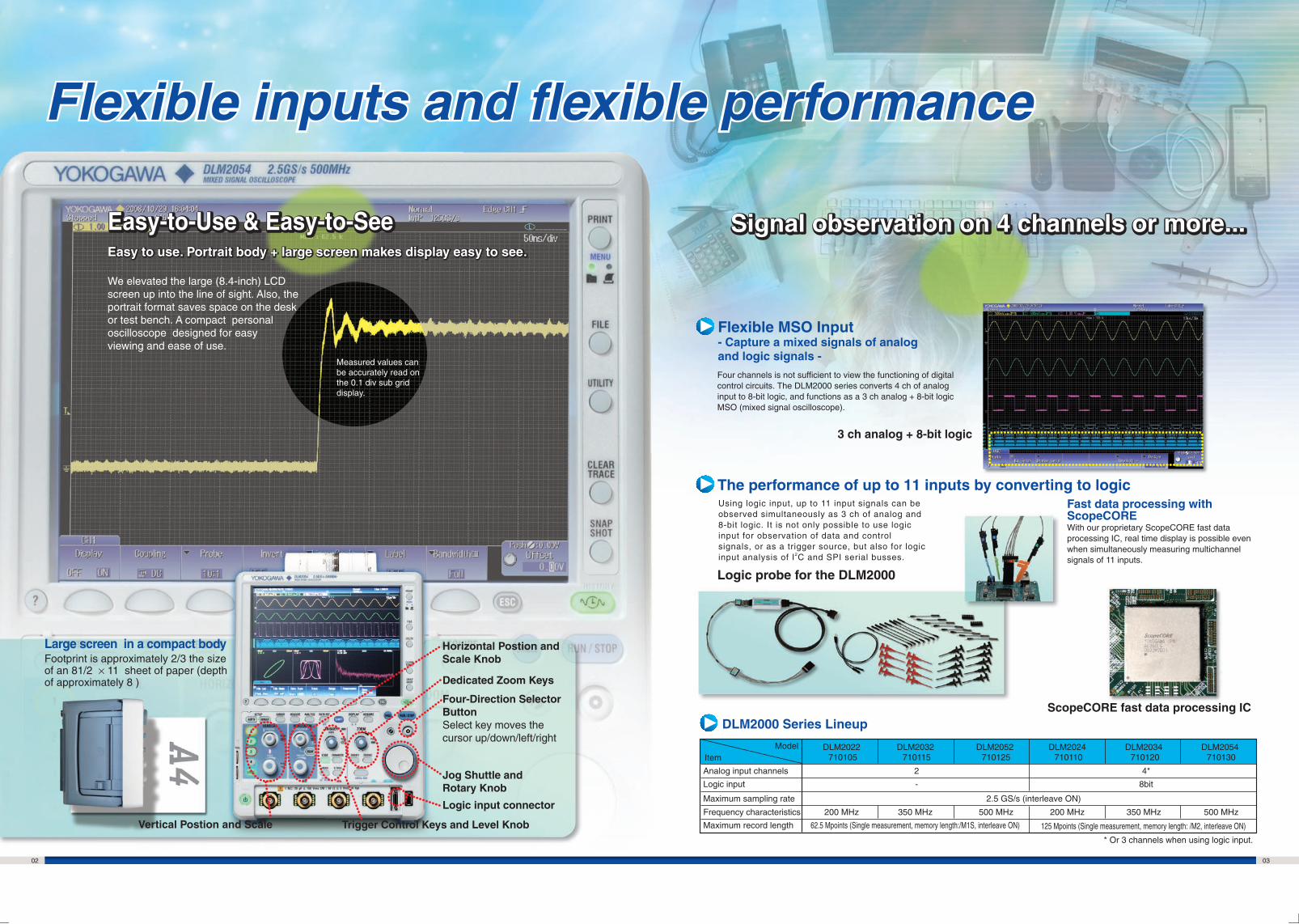
Four channels is not sufficient to view the functioning of digital control circuits. The DLM2000 series converts 4 ch of analog input to 8-bit logic, and functions as a 3 ch analog + 8-bit logic MSO (mixed signal oscilloscope).
Large screen in a compact body
Dedicated Zoom Keys
Jog Shuttle and Rotary Knob
Four-Direction Selector ButtonSelect key moves the cursor up/down/left/right
Using logic input, up to 11 input signals can be observed simultaneously as 3 ch of analog and 8-bit logic. It is not only possible to use logic input for observation of data and control signals, or as a trigger source, but also for logic input analysis of I2C and SPI serial busses.
Fast data processing with ScopeCORE With our proprietary ScopeCORE fast data processing IC, real time display is possible even when simultaneously measuring multichannel signals of 11 inputs.
Footprint is approximately 2/3 the size of an 81/2 × 11 sheet of paper (depth of approximately 8 )
Measured values can be accurately read on the 0.1 div sub grid display.
Logic input connector
Flexible MSO Input- Capture a mixed signals of analog and logic signals -
3 ch analog + 8-bit logic
The performance of up to 11 inputs by converting to logic
We elevated the large (8.4-inch) LCD screen up into the line of sight. Also, the portrait format saves space on the desk or test bench. A compact personal oscilloscope designed for easy viewing and ease of use.
Signal observation on 4 channels or more...Signal observation on 4 channels or more...Easy-to-Use & Easy-to-SeeEasy-to-Use & Easy-to-See
Frequency characteristics
Maximum record length
Item
2.5 GS/s (interleave ON)
Easy to use. Portrait body + large screen makes display easy to see. Easy to use. Portrait body + large screen makes display easy to see.
Flexible inputs and flexible performanceFlexible inputs and flexible performance
04 05
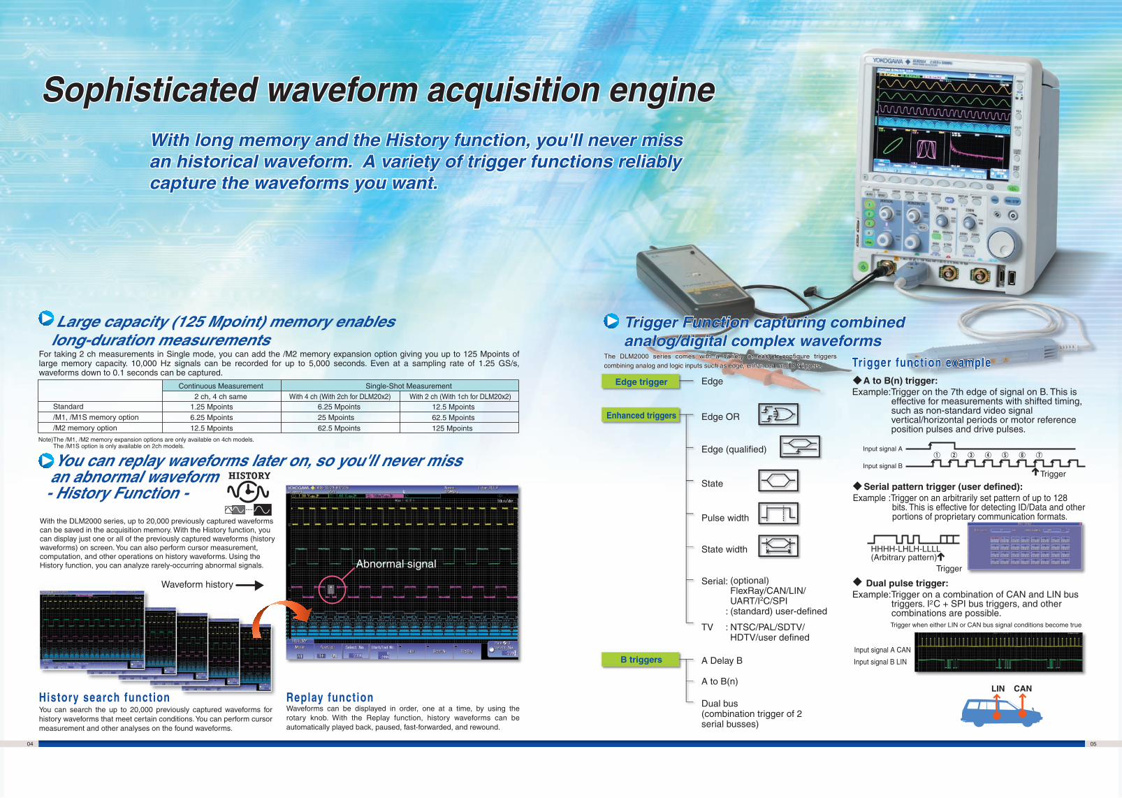
With 4 ch (With 2ch for DLM20x2) With 2 ch (With 1ch for DLM20x2)Standard/M1, /M1S memory option /M2 memory option
2 ch, 4 ch same6.25 Mpoints25 Mpoints62.5 Mpoints
1.25 Mpoints6.25 Mpoints12.5 Mpoints
For taking 2 ch measurements in Single mode, you can add the /M2 memory expansion option giving you up to 125 Mpoints of large memory capacity. 10,000 Hz signals can be recorded for up to 5,000 seconds. Even at a sampling rate of 1.25 GS/s, waveforms down to 0.1 seconds can be captured.
You can search the up to 20,000 previously captured waveforms for history waveforms that meet certain conditions. You can perform cursor measurement and other analyses on the found waveforms.
The DLM2000 series comes with a variety of easy-to-configure triggers combining analog and logic inputs such as edge, enhanced, and B triggers.The DLM2000 series comes with a variety of easy-to-configure triggers combining analog and logic inputs such as edge, enhanced, and B triggers.
A to B(n) trigger:Example:Trigger on the 7th edge of signal on B. This is
effective for measurements with shifted timing, such as non-standard video signal vertical/horizontal periods or motor reference position pulses and drive pulses.
Serial pattern trigger (user defined): Example :Trigger on an arbitrarily set pattern of up to 128
bits. This is effective for detecting ID/Data and other portions of proprietary communication formats.
Large capacity (125 Mpoint) memory enables long-duration measurements
You can replay waveforms later on, so you'll never miss an abnormal waveform
- History Function -
Waveforms can be displayed in order, one at a time, by using the rotary knob. With the Replay function, history waveforms can be automatically played back, paused, fast-forwarded, and rewound.
Edge
Note)The /M1, /M2 memory expansion options are only available on 4ch models. The /M1S option is only available on 2ch models.
With the DLM2000 series, up to 20,000 previously captured waveforms can be saved in the acquisition memory. With the History function, you can display just one or all of the previously captured waveforms (history waveforms) on screen. You can also perform cursor measurement, computation, and other operations on history waveforms. Using the History function, you can analyze rarely-occurring abnormal signals.
Waveform history
Abnormal signal
History search function Replay function
Trigger Function capturing combined analog/digital complex waveformsTrigger Function capturing combined analog/digital complex waveforms
Edge OR
Edge (qualified)
State
Pulse width
State width
Serial:
TV
A Delay B
A to B(n)
Dual bus (combination trigger of 2 serial busses)
Trigger function exampleTrigger function example
Input signal A
Input signal BTrigger
HHHH-LHLH-LLLL(Arbitrary pattern)
Trigger
Dual pulse trigger: Example:Trigger on a combination of CAN and LIN bus
triggers. I2C + SPI bus triggers, and other combinations are possible.
Trigger when either LIN or CAN bus signal conditions become true
Input signal A CAN
Input signal B LIN
LIN CAN
(optional)FlexRay/CAN/LIN/UART/I2C/SPI
: (standard) user-defined
: NTSC/PAL/SDTV/ HDTV/user defined
Single-Shot MeasurementContinuous Measurement
12.5 Mpoints62.5 Mpoints125 Mpoints
Enhanced triggers
Edge trigger
B triggers
Sophisticated waveform acquisition engineSophisticated waveform acquisition engineWith long memory and the History function, you'll never miss an historical waveform. A variety of trigger functions reliably capture the waveforms you want.
With long memory and the History function, you'll never miss an historical waveform. A variety of trigger functions reliably capture the waveforms you want.
Zoom1 Zoom2
06 07
The DLM2000 series has two types of filters, one processed at the input circuit and one based on MATH functions. These filters are effective for rejecting unwanted signals, allowing observation of only the desired bandwidths.
Each channel has 14 low pass filters available from 8 kHz to 200 MHz. Waveforms of limited bandwidths are stored in internal memory.
By pressing the SNAPSHOT key to the lower right of the screen, you can freeze a white trace of the currently displayed waveform on the screen. You can press the key repeatedly and conveniently leave traces for comparing multiple waveforms. Also, snapshot data recorded on screen can be saved or loaded as files, and can be recalled for use as reference waveforms when making comparisons.
Thumbnails of waveform data, waveform image data, and Wave-Zone files can be displayed. The image and file names are shown so that you can view screen image contents while copying or deleting files. A file can be enlarged to confirm the data.
GO/NO-GO can be determined using trigger conditions, zone waveforms, measurement parameters, and other criteria. For NO-GO, actions can be carried out at the same time such as sounding a buzzer, saving the current waveform, or sending notification to a designated e-mail address. Waveforms in which an abnormality occurred can be saved for confirmation and analysis of the phenomena at a later time.
You can view detailed graphical explanations of the oscilloscope's functions by pressing the "?" key in the lower left of the screen. This lets you get help on functions and operations on screen without having to consult the user's manual.
Real time filters
The input waveform can be filtered using an IIR filter, which is a MATH function. Filtered waveforms can be displayed at the same time as the input waveform for comparison. You can select low pass or high pass filters.
Cutoff frequency setting range : 0.01 Hz to 500 MHz
Computed digital filters
Because the DLM2000 series lets you set zoom factors independently, you can display two zoomed waveforms with different time axis scales at the same time. Also, using the Auto Scroll function, you can automatically scroll waveforms captured in long memory and change the zoomed location. With Auto Scroll you can choose forward, backward, fast-forward, scroll speed, and other control options.
• Waveform search criteriaEdge, edge (with conditions), state pattern, pulse width, state width, serial bus (only on models with the serial bus analysis option)
Searching for waveforms in zones created by moving measured waveforms up/down/left/right.
Search for waveforms that pass through/do not pass through a rectangular zone placed on screen.
Searching for data in a single screen: the Zoom Search functionThis function searches captured waveforms in the long memory and displays waveforms that meet the search criteria in the zoom area. The locations of the found waveforms are marked on screen ( shows the current location).
Zoom two locations simultaneously
Two types of waveform searching:Normally, searching for data takes time and costs money, and long memory is useless without functions for extracting desired data from a large capacity memory. That's why the DLM2000 series does not simply offer long memory, it also provides powerful waveform search functions.
Large capacity memory gives you a variety of waveform search functions.
DLM 2000 SeriesCapture & Display Zoom and Search Functions DLM 2000 SeriesUseful Functions Fastest and most capable analysis
Cursors can be placed on the displayed waveform from signal data, and various measurement values at the intersection of the cursor and waveform can be displayed. There are six types of cursor; ∆T, ∆V, ∆T& ∆V, Marker, Degree Cursor.
Twenty-nine waveform parameters are included such as: maximum, minimum, peak-to-peak, pulse width, period, frequency, rise/fall time, and duty ratio. Automated measurement can be performed using up to 30 of these waveform parameters. Also, waveform parameters can be measured repeatedly, and the statistical values displayed (mean, maximum, minimum, standard deviation, etc.).
Waveform parameters such as period, pulse width, and amplitude can be measured repeatedly and displayed in graphs. In a single screen you can observe period-by-period fluctuations, compute amplitudes every screen using multiple waveforms, and display amplitudes as trends. You can also display histograms referencing the voltage or time axis using values from repeated automated measurement of waveform parameters.
FFT analysis
Processing with built-in filters
Computed waveform
Dedicated Zoom keys
Auto Scroll menu
Waveform search using edge criterion
Criterion extraction
Simultaneous level and time difference measurement with the ∆T&∆V cursor
"SNAP SHOT"key
Using snapshots (white waveforms)
Abnormal waveform detected
Action specified for NO-GO
Trend display of waveform parameters Histogram display using the time axis
Thumbnails of saved files Thumbnail can be viewed full-size
Real time filter with optimum noise reduction supports a wide range of frequencies (from 8 kHz to 200 MHz)
Filtering of a PWM waveform using computation
Zooms into two different points
Search results marked
Displays trends of peak-to-peak or pulse width per cycle
Analyzes frequency spectrumsMeasures voltage/time differences automatically
Displays stored files in thumbnail formatKeeps waveforms with one push
Can check functions with graphical online helpHas a GO/NO-GO function
Buzzer Output to printer
Save waveform data file
E-mail transmission
Up to 2 FFT analyses can be performed simultaneously. FFT can be performed on computed waveforms in addition to the actual waveforms on CH1 to CH4. Analysis can be performaed of the frequency components of waveforms filtered for limited bandwidth, of frequency for changes in period of rotary objects, and other phenomena.
— Measure function and statistics — — Trend and histogram displays —
— Cursor Measurement — — FFT analysis —
— Snapshot — — Thumbnails of saved files —
— Action on trigger — — Graphical online help —
Zone created from measured waveforms
Place square zone and search
Searching for history waveforms: the History Search functionCriteria can be specified for extracting desired waveforms from up to 20,000 previously captured waveforms.
Off-line waveform display and analysis
Waveform monitoring on a PC
Data transfer to a PC
Command controlCustom software development
MATLAB Tool KitRemote control from MATLAB and data file importing.
Free Software Optional SoftwareXviewer –Advanced Analysis–Advanced and useful functions are supported. Good for precise, off-line waveform analysis.
• Waveform observation and analysis • Cursor, Parameteric Measure• Statistical Analysis • Multiple file display • Advanced waveform operations • Comment, marking, printing and making report• Optional Math computation feature • Remote monitor • Instruments communication function • Transferring waveform & image files
DL-TermInteractive tool
LabVIEW instrument driver
XviewerLITE –Basic check–Zoom, V-cursor, conversion to CSV format
XWirepullerRemote monitor and operationTransferring image files
Control library “TMCTL”For Visual Studio
Trial version available
Trial versionavailable
Trial versionavailable
Related Accessories
Accessories
Power supply analysis option (/G4)
08 09
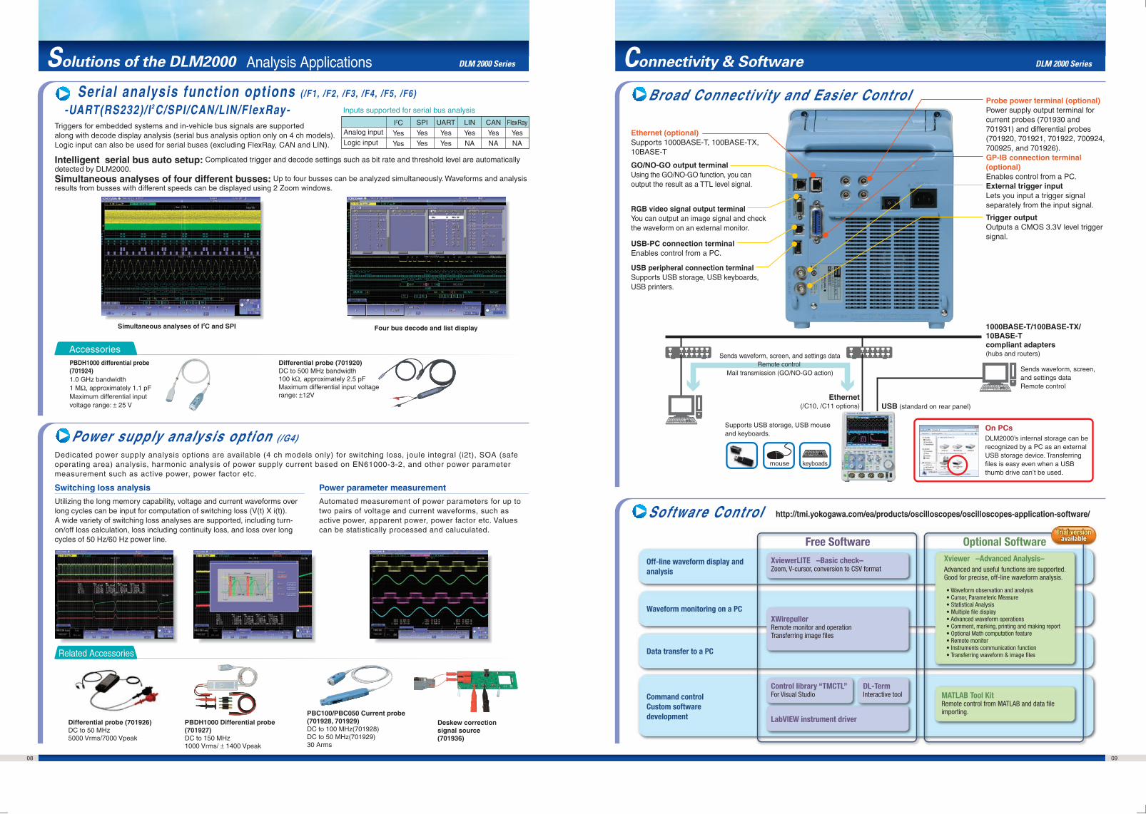
Triggers for embedded systems and in-vehicle bus signals are supported along with decode display analysis (serial bus analysis option only on 4 ch models).Logic input can also be used for serial buses (excluding FlexRay, CAN and LIN).
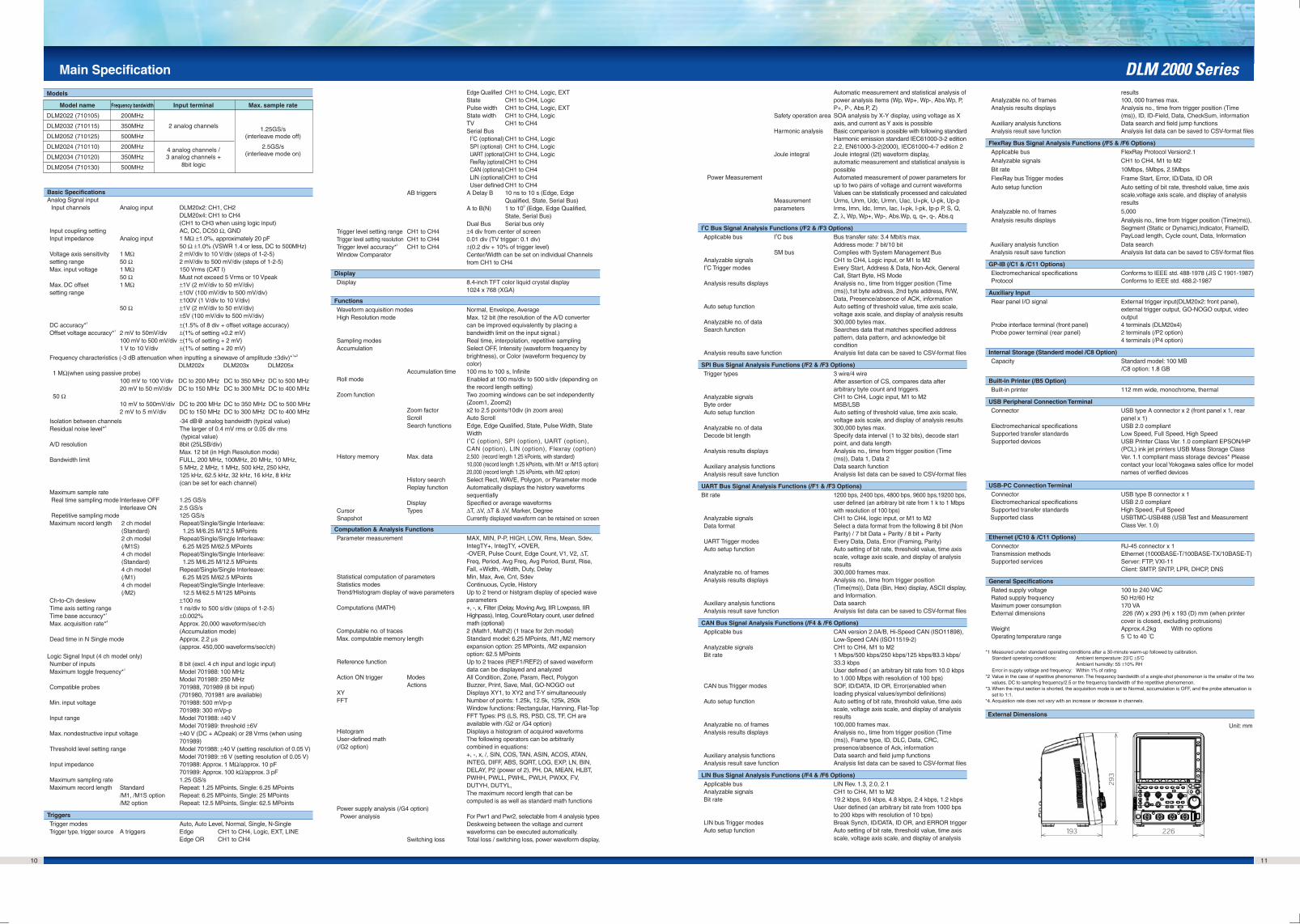
Broad Connectivity and Easier Control
Software Control
Dedicated power supply analysis options are available (4 ch models only) for switching loss, joule integral (i2t), SOA (safe operating area) analysis, harmonic analysis of power supply current based on EN61000-3-2, and other power parameter measurement such as active power, power factor etc.
PBDH1000 differential probe (701924)1.0 GHz bandwidth1 MΩ, approximately 1.1 pFMaximum differential input voltage range: ± 25 V
1000BASE-T/100BASE-TX/ 10BASE-T compliant adapters(hubs and routers)
Sends waveform, screen, and settings dataRemote control
Sends waveform, screen, and settings dataRemote control
Probe power terminal (optional)Power supply output terminal for current probes (701930 and 701931) and differential probes (701920, 701921, 701922, 700924, 700925, and 701926).
Differential probe (701920)DC to 500 MHz bandwidth100 kΩ, approximately 2.5 pFMaximum differential input voltage range: ±12V
Switching loss analysis
Utilizing the long memory capability, voltage and current waveforms over long cycles can be input for computation of switching loss (V(t) X i(t)).A wide variety of switching loss analyses are supported, including turn-on/off loss calculation, loss including continuity loss, and loss over long cycles of 50 Hz/60 Hz power line.
Intelligent serial bus auto setup: Complicated trigger and decode settings such as bit rate and threshold level are automatically detected by DLM2000.Simultaneous analyses of four different busses: Up to four busses can be analyzed simultaneously. Waveforms and analysis results from busses with different speeds can be displayed using 2 Zoom windows.
Automated measurement of power parameters for up to two pairs of voltage and current waveforms, such as active power, apparent power, power factor etc. Values can be statistically processed and caluculated.
GP-IB connection terminal (optional)Enables control from a PC.
Trigger outputOutputs a CMOS 3.3V level trigger signal.
External trigger inputLets you input a trigger signal separately from the input signal.
GO/NO-GO output terminalUsing the GO/NO-GO function, you can output the result as a TTL level signal.
RGB video signal output terminalYou can output an image signal and check the waveform on an external monitor.
USB-PC connection terminalEnables control from a PC.
USB peripheral connection terminalSupports USB storage, USB keyboards, USB printers.
DLM 2000 SeriesSolutions of the DLM2000 Connectivity & Software DLM 2000 SeriesAnalysis Applications
Serial analysis function options (/F1, /F2, /F3, /F4, /F5, /F6)
-UART(RS232)/ I 2C/SPI/CAN/LIN/FlexRay- Inputs supported for serial bus analysis
Analog input
Logic input
Simultaneous analyses of I2C and SPI Four bus decode and list display
CAN
Yes
NA
FlexRay
Yes
NA
LIN
Yes
NA
UART
Yes
Yes
SPI
Yes
Yes
I2C
Yes
Yes
mouse keyboads
Supports USB storage, USB mouse and keyboards.
On PCsDLM2000’s internal storage can be recognized by a PC as an external USB storage device. Transferring files is easy even when a USB thumb drive can’t be used.
Differential probe (701926)DC to 50 MHz5000 Vrms/7000 Vpeak
DLM2024 (710110) 200MHz 4 analog channels / 2.5GS/s
DLM2034 (710120) 350MHz 3 analog channels + (interleave mode on)
DLM2054 (710130) 500MHz 8bit logic
Models
*1 Measured under standard operating conditions after a 30-minute warm-up followed by calibration. Standard operating conditions: Ambient temperature: 23 C ±5 C
Ambient humidity: 55 ±10% RHError in supply voltage and frequency: Within 1% of rating
*2 Value in the case of repetitive phenomenon. The frequency bandwidth of a single-shot phenomenon is the smaller of the two values, DC to sampling frequency/2.5 or the frequency bandwidth of the repetitive phenomenon.
*3.When the input section is shorted, the acquisition mode is set to Normal, accumulation is OFF, and the probe attenuation is set to 1:1.
*4.Acquisition rate does not vary with an increase or decrease in channels.
DLM 2000 Series
Unit: mm
Basic SpecificationsAnalog Signal input Input channels Analog input DLM20x2: CH1, CH2
DLM20x4: CH1 to CH4(CH1 to CH3 when using logic input)
Input coupling setting AC, DC, DC50 Ω, GND Input impedance Analog input 1 MΩ ±1.0%, approximately 20 pF
50 Ω ±1.0% (VSWR 1.4 or less, DC to 500MHz) Voltage axis sensitivity 1 MΩ 2 mV/div to 10 V/div (steps of 1-2-5)setting range 50 Ω 2 mV/div to 500 mV/div (steps of 1-2-5)Max. input voltage 1 MΩ 150 Vrms (CAT I)
50 Ω Must not exceed 5 Vrms or 10 VpeakMax. DC offset 1 MΩ ±1V (2 mV/div to 50 mV/div)setting range ±10V (100 mV/div to 500 mV/div)
±100V (1 V/div to 10 V/div)50 Ω ±1V (2 mV/div to 50 mV/div)
±5V (100 mV/div to 500 mV/div)
DC accuracy*1 ±(1.5% of 8 div + offset voltage accuracy)Offset voltage accuracy*1 2 mV to 50mV/div ±(1% of setting +0.2 mV)
100 mV to 500 mV/div ±(1% of setting + 2 mV)1 V to 10 V/div ±(1% of setting + 20 mV)
Frequency characteristics (-3 dB attenuation when inputting a sinewave of amplitude ±3div)*1*2
DLM202x DLM203x DLM205x 1 MΩ(when using passive probe)
100 mV to 100 V/div DC to 200 MHz DC to 350 MHz DC to 500 MHz20 mV to 50 mV/div DC to 150 MHz DC to 300 MHz DC to 400 MHz
50 Ω10 mV to 500mV/div DC to 200 MHz DC to 350 MHz DC to 500 MHz2 mV to 5 mV/div DC to 150 MHz DC to 300 MHz DC to 400 MHz
Isolation between channels -34 dB@ analog bandwidth (typical value) Residual noise level*3 The larger of 0.4 mV rms or 0.05 div rms
(typical value) A/D resolution 8bit (25LSB/div)
Max. 12 bit (in High Resolution mode)Bandwidth limit FULL, 200 MHz, 100MHz, 20 MHz, 10 MHz,
5 MHz, 2 MHz, 1 MHz, 500 kHz, 250 kHz, 125 kHz, 62.5 kHz, 32 kHz, 16 kHz, 8 kHz (can be set for each channel)
Maximum sample rate Real time sampling mode Interleave OFF 1.25 GS/s
Interleave ON 2.5 GS/s Repetitive sampling mode 125 GS/sMaximum record length 2 ch model Repeat/Single/Single Interleave:
4 ch model Repeat/Single/Single Interleave: (Standard) 1.25 M/6.25 M/12.5 MPoints
4 ch model Repeat/Single/Single Interleave: (/M1) 6.25 M/25 M/62.5 MPoints 4 ch model Repeat/Single/Single Interleave: (/M2) 12.5 M/62.5 M/125 MPoints
Ch-to-Ch deskew ±100 ns Time axis setting range 1 ns/div to 500 s/div (steps of 1-2-5)Time base accuracy*1 ±0.002% Max. acquisition rate*4 Approx. 20,000 waveform/sec/ch
(Accumulation mode)Dead time in N Single mode Approx. 2.2 µs
(approx. 450,000 waveforms/sec/ch)
Logic Signal Input (4 ch model only) Number of inputs 8 bit (excl. 4 ch input and logic input)Maximum toggle frequency*1 Model 701988: 100 MHz
Model 701989: 250 MHzCompatible probes 701988, 701989 (8 bit input)
(701980, 701981 are available) Min. input voltage 701988: 500 mVp-p
701989: 300 mVp-p Input range Model 701988: ±40 V
Model 701989: threshold ±6V Max. nondestructive input voltage ±40 V (DC + ACpeak) or 28 Vrms (when using
701989)Threshold level setting range Model 701988: ±40 V (setting resolution of 0.05 V)
Model 701989: ±6 V (setting resolution of 0.05 V)Input impedance 701988: Approx. 1 MΩ/approx. 10 pF
701989: Approx. 100 kΩ/approx. 3 pFMaximum sampling rate 1.25 GS/s Maximum record length Standard Repeat: 1.25 MPoints, Single: 6.25 MPoints
TriggersTrigger modes Auto, Auto Level, Normal, Single, N-SingleTrigger type, trigger source A triggers Edge CH1 to CH4, Logic, EXT, LINE
Edge OR CH1 to CH4
Edge Qualified CH1 to CH4, Logic, EXTState CH1 to CH4, LogicPulse width CH1 to CH4, Logic, EXTState width CH1 to CH4, LogicTV CH1 to CH4Serial Bus I2C (optional) CH1 to CH4, Logic SPI (optional) CH1 to CH4, Logic UART (optional)CH1 to CH4, Logic FlexRay (optional)CH1 to CH4 CAN (optional)CH1 to CH4 LIN (optional)CH1 to CH4 User defined CH1 to CH4
AB triggers A Delay B 10 ns to 10 s (Edge, Edge Qualified, State, Serial Bus)
A to B(N) 1 to 109 (Edge, Edge Qualified, State, Serial Bus)
Dual Bus Serial bus onlyTrigger level setting range CH1 to CH4 ±4 div from center of screenTrigger level setting resolution CH1 to CH4 0.01 div (TV trigger: 0.1 div)Trigger level accuracy*1 CH1 to CH4 ±(0.2 div + 10% of trigger level)Window Comparator Center/Width can be set on individual Channels
from CH1 to CH4
DisplayDisplay 8.4-inch TFT color liquid crystal display
1024 x 768 (XGA)
FunctionsWaveform acquisition modes Normal, Envelope, Average High Resolution mode Max. 12 bit (the resolution of the A/D converter
can be improved equivalently by placing a bandwidth limit on the input signal.)
Sampling modes Real time, interpolation, repetitive samplingAccumulation Select OFF, Intensity (waveform frequency by
brightness), or Color (waveform frequency by color)
Accumulation time 100 ms to 100 s, Infinite Roll mode Enabled at 100 ms/div to 500 s/div (depending on
the record length setting) Zoom function Two zooming windows can be set independently
(Zoom1, Zoom2) Zoom factor x2 to 2.5 points/10div (in zoom area)Scroll Auto Scroll Search functions Edge, Edge Qualified, State, Pulse Width, State
Width I2C (option), SPI (option), UART (option), CAN (option), LIN (option), Flexray (option)
History memory Max. data 2,500 (record length 1.25 kPoints, with standard)10,000 (record length 1.25 kPoints, with /M1 or /M1S option)20,000 (record length 1.25 kPoints, with /M2 option)
History search Select Rect, WAVE, Polygon, or Parameter modeReplay function Automatically displays the history waveforms
sequentiallyDisplay Specified or average waveforms
Cursor Types ∆T, ∆V, ∆T & ∆V, Marker, Degree Snapshot Currently displayed waveform can be retained on screen
Statistical computation of parameters Min, Max, Ave, Cnt, Sdev Statistics modes Continuous, Cycle, History Trend/Histogram display of wave parameters Up to 2 trend or histgram display of specied wave
Reference function Up to 2 traces (REF1/REF2) of saved waveform data can be displayed and analyzed
Action ON trigger Modes All Condition, Zone, Param, Rect, Polygon Actions Buzzer, Print, Save, Mail, GO-NOGO out
XY Displays XY1, to XY2 and T-Y simultaneouslyFFT Number of points: 1.25k, 12.5k, 125k, 250k
Window functions: Rectangular, Hanning, Flat-TopFFT Types: PS (LS, RS, PSD, CS, TF, CH are available with /G2 or /G4 option)
Histogram Displays a histogram of acquired waveformsUser-defined math The following operators can be arbitrarily(/G2 option) combined in equations:
+, -, x, /, SIN, COS, TAN, ASIN, ACOS, ATAN, INTEG, DIFF, ABS, SQRT, LOG, EXP, LN, BIN,DELAY, P2 (power of 2), PH, DA, MEAN, HLBT,PWHH, PWLL, PWHL, PWLH, PWXX, FV,DUTYH, DUTYL,The maximum record length that can becomputed is as well as standard math functions
Power supply analysis (/G4 option)Power analysis For Pwr1 and Pwr2, selectable from 4 analysis types
Deskweing between the voltage and current waveforms can be executed automatically.
Switching loss Total loss / switching loss, power waveform display,
Automatic measurement and statistical analysis of power analysis items (Wp, Wp+, Wp-, Abs.Wp, P, P+, P-, Abs.P, Z)
Safety operation area SOA analysis by X-Y display, using voltage as X axis, and current as Y axis is possible
Harmonic analysis Basic comparison is possible with following standardHarmonic emission standard IEC61000-3-2 edition2.2, EN61000-3-2(2000), IEC61000-4-7 edition 2
Joule integral Joule integral (I2t) waveform display, automatic measurement and statistical analysis is possible
Power Measurement Automated measurement of power parameters for up to two pairs of voltage and current waveformsValues can be statistically processed and calculated
I2C Bus Signal Analysis Functions (/F2 & /F3 Options)Applicable bus I2C bus Bus transfer rate: 3.4 Mbit/s max.
Address mode: 7 bit/10 bit SM bus Complies with System Management Bus
Analyzable signals CH1 to CH4, Logic input, or M1 to M2I2C Trigger modes Every Start, Address & Data, Non-Ack, General
Call, Start Byte, HS Mode Analysis results displays Analysis no., time from trigger position (Time
(ms)),1st byte address, 2nd byte address, R/W, Data, Presence/absence of ACK, information
Auto setup function Auto setting of threshold value, time axis scale, voltage axis scale, and display of analysis results
Analyzable no. of data 300,000 bytes max. Search function Searches data that matches specified address
pattern, data pattern, and acknowledge bit condition
Analysis results save function Analysis list data can be saved to CSV-format files
SPI Bus Signal Analysis Functions (/F2 & /F3 Options)Trigger types 3 wire/4 wire
After assertion of CS, compares data after arbitrary byte count and triggers.
Analyzable signals CH1 to CH4, Logic input, M1 to M2Byte order MSB/LSB Auto setup function Auto setting of threshold value, time axis scale,
voltage axis scale, and display of analysis resultsAnalyzable no. of data 300,000 bytes max. Decode bit length Specify data interval (1 to 32 bits), decode start
point, and data length Analysis results displays Analysis no., time from trigger position (Time
(ms)), Data 1, Data 2Auxiliary analysis functions Data search functionAnalysis result save function Analysis list data can be saved to CSV-format files
UART Bus Signal Analysis Functions (/F1 & /F3 Options)Bit rate 1200 bps, 2400 bps, 4800 bps, 9600 bps,19200 bps,
user defined (an arbitrary bit rate from 1 k to 1 Mbps with resolution of 100 bps)
Analyzable signals CH1 to CH4, logic input, or M1 to M2Data format Select a data format from the following 8 bit (Non
Parity) / 7 bit Data + Parity / 8 bit + ParityUART Trigger modes Every Data, Data, Error (Framing, Parity) Auto setup function Auto setting of bit rate, threshold value, time axis
scale, voltage axis scale, and display of analysis results
Analyzable no. of frames 300,000 frames max.Analysis results displays Analysis no., time from trigger position
(Time(ms)), Data (Bin, Hex) display, ASCII display, and Information.
Auxiliary analysis functions Data searchAnalysis result save function Analysis list data can be saved to CSV-format files
CAN Bus Signal Analysis Functions (/F4 & /F6 Options) Applicable bus CAN version 2.0A/B, Hi-Speed CAN (ISO11898),
Low-Speed CAN (ISO11519-2)Analyzable signals CH1 to CH4, M1 to M2Bit rate 1 Mbps/500 kbps/250 kbps/125 kbps/83.3 kbps/
33.3 kbpsUser defined ( an arbitrary bit rate from 10.0 kbps to 1.000 Mbps with resolution of 100 bps)
CAN bus Trigger modes SOF, ID/DATA, ID OR, Error(enabled when loading physical values/symbol definitions)
Auto setup function Auto setting of bit rate, threshold value, time axis scale, voltage axis scale, and display of analysis results
Analyzable no. of frames 100,000 frames max. Analysis results displays Analysis no., time from trigger position (Time
(ms)), Frame type, ID, DLC, Data, CRC, presence/absence of Ack, information
Auxiliary analysis functions Data search and field jump functionsAnalysis result save function Analysis list data can be saved to CSV-format files
LIN Bus Signal Analysis Functions (/F4 & /F6 Options)Applicable bus LIN Rev. 1.3, 2.0, 2.1 Analyzable signals CH1 to CH4, M1 to M2Bit rate 19.2 kbps, 9.6 kbps, 4.8 kbps, 2.4 kbps, 1.2 kbps
User defined (an arbitrary bit rate from 1000 bps to 200 kbps with resolution of 10 bps)
LIN bus Trigger modes Break Synch, ID/DATA, ID OR, and ERROR triggerAuto setup function Auto setting of bit rate, threshold value, time axis
scale, voltage axis scale, and display of analysis
results Analyzable no. of frames 100, 000 frames max. Analysis results displays Analysis no., time from trigger position (Time
(ms)), ID, ID-Field, Data, CheckSum, information Auxiliary analysis functions Data search and field jump functionsAnalysis result save function Analysis list data can be saved to CSV-format files
FlexRay Bus Signal Analysis Functions (/F5 & /F6 Options)Applicable bus FlexRay Protocol Version2.1Analyzable signals CH1 to CH4, M1 to M2Bit rate 10Mbps, 5Mbps, 2.5MbpsFlexRay bus Trigger modes Frame Start, Error, ID/Data, ID ORAuto setup function Auto setting of bit rate, threshold value, time axis
scale,voltage axis scale, and display of analysis results
Analyzable no. of frames 5,000Analysis results displays Analysis no., time from trigger position (Time(ms)),
Segment (Static or Dynamic),Indicator, FrameID, PayLoad length, Cycle count, Data, Information
Auxiliary analysis function Data search Analysis result save function Analysis list data can be saved to CSV-format files
GP-IB (/C1 & /C11 Options)Electromechanical specifications Conforms to IEEE std. 488-1978 (JIS C 1901-1987)Protocol Conforms to IEEE std. 488.2-1987
Auxiliary InputRear panel I/O signal External trigger input(DLM20x2: front panel),
external trigger output, GO-NOGO output, video output
Internal Storage (Standerd model /C8 Option)Capacity Standard model: 100 MB
/C8 option: 1.8 GB
Built-in Printer (/B5 Option)Built-in printer 112 mm wide, monochrome, thermal
USB Peripheral Connection TerminalConnector USB type A connector x 2 (front panel x 1, rear
panel x 1)Electromechanical specifications USB 2.0 compliantSupported transfer standards Low Speed, Full Speed, High SpeedSupported devices USB Printer Class Ver. 1.0 compliant EPSON/HP
(PCL) ink jet printers USB Mass Storage Class Ver. 1.1 compliant mass storage devices* Please contact your local Yokogawa sales office for model names of verified devices
USB-PC Connection TerminalConnector USB type B connector x 1 Electromechanical specifications USB 2.0 compliantSupported transfer standards High Speed, Full Speed
Supported class USBTMC-USB488 (USB Test and Measurement Class Ver. 1.0)
General SpecificationsRated supply voltage 100 to 240 VAC Rated supply frequency 50 Hz/60 Hz Maximum power consumption 170 VA External dimensions 226 (W) x 293 (H) x 193 (D) mm (when printer
cover is closed, excluding protrusions)Weight Approx.4.2kg With no optionsOperating temperature range 5 C to 40 C
External Dimensions
Mixed Signal Oscilloscope
Special SiteSpecial SiteDLM 2000SeriesSeries
http://www.DLM2000.net/Product demonstration (Flash) now available Check here for updated firmware information. Manual download service! *
• Yokogawa's electrical products are developed and produced in facilities that have received ISO14001 approval.• In order to protect the global environment,Yokogawa's electrical products are designed in accordance with Yokogawa's Environmentally Friendy Product
Design Guidelines and Product Design Assessment Criteria.
Yokogawa's Approach to Preserving the Global Environment
Model and Suffix Codes Standard Main Unit Accessories
Accessory Models
DLM 2000 Series
Model Suffix code Description Part Name Quantity
Name Model Specification
Bulletin 7101-00E
DLM 2000DLM 2000DLM 2000Mixed Signal Oscilloscope
SeriesSeriesSeries
Lineup includes 200 MHz, 350 MHz, 500 MHz bandwidth models
Lightweight and compact
Large 8.4-inch LCD display
Long memory: Up to 125M points (with /M2 option)
High speed sampling: Up to 2.5 GS/s (1.25 GS/s with 4 ch)
710105710110*1
710115710120*1
710125710130*1
Power cord
Language
Option
Digital Oscilloscope DLM2022 2ch, 200MHzMixed Signal Oscilloscope DLM2024 4ch, 200MHzDigital Oscilloscope DLM2032 2ch, 350MHzMixed Signal Oscilloscope DLM2034 4ch, 350MHzDigital Oscilloscope DLM2052 2ch, 500MHzMixed Signal Oscilloscope DLM2054 4ch, 500MHzUL/CSA standardVDE standardBS standardAS standardGB standardEnglish Menu and PanelChinese Menu and PanelKorean Menu and PanelGerman Menu and PanelFrench Menu and PanelItalian Menu and PanelSpanish Menu and PanelNo switchable logic input (4 ch model only)Built-in printer"Memory expansion option (4 ch model only)During continuous measurement: 6.25 Mpoints; Single mode: 25 Mpoints (when interleave mode ON: 62.5 Mpoints)""Memory expansion option (4 ch model only)During continuous measurement: 12.5 Mpoints; Single mode: 62.5 Mpoints (when interleave mode ON: 125 Mpoints)""Memory expansion option (2 ch model only)During continuous measurement: 6.25 Mpoints; Single mode: 25 Mpoints (when interleave mode ON: 62.5 Mpoints)"Probe power for 2 ch modelsProbe power for 4 ch modelsGP-IB InterfaceEthernet InterfaceGP-IB + Ethernet InterfaceInternal storage (1.8 GB)User defined math (4 ch model only)"Power supply analysis function (includes /G2) (4 ch model only)"UART trigger and analysis (4 ch model only) I2C + SPI trigger and analysis (4 ch model only) UART + I2C + SPI trigger and analysis (4 ch model only) CAN + LIN trigger and analysis (4 ch model only)FlexRay trigger and analysis (4 ch model only) FlexRay+CAN+LIN trigger and analysis (4 ch model only)Attach two 701946 probes (For 2ch, 200 MHz models)Attach four 701946 probes (For 4ch, 200 MHz models)Attach two 701946 probes (For 2ch, 350/500 MHz models)Attach four 701946 probes (For 4ch, 350/500 MHz models)
Power cordPassive probe, model 701938 (200 MHz, 1.5 m)For models 710105, 710110*1
1 MΩ input resistance, toggle frequency of 100 MHz 100 kΩ input resistance, toggle frequency of 250 MHz 10 MΩ (10:1), 200 MHz, 1.5 m10 MΩ (10:1), 500 MHz, 1.3 m 10 MΩ (10:1), 500 MHz, 1.3 mDC to 900 MHz bandwidth/2.5MΩ/1.8pF DC to 1 GHz bandwidth/100kΩ/0.9pF DC to 400 MHz, 1.2 m, 1000 Vrms DC to 250 MHz, 3 m, 1000 VrmsDC to 100 MHz bandwidth/max. ±700 V DC to 200 MHz bandwidth/max. ±20 V DC to 1 GHz bandwidth/1MΩ/max. ±25 VDC to 50 MHz bandwidth, 5000 Vrms/7000 VpeakDC to 150 MHz bandwidth, max, ±1400VDC to 100 MHz bandwidth/max. ±1400 V DC to 15 MHz bandwidth/max. ±500 V DC to 500 MHz bandwidth/max. ±12 V DC to 50 MHz bandwidth, 30 Arms DC to 100 MHz bandwidth, 30 Arms DC to 10 MHz bandwidth, 150 Arms DC to 2 MHz bandwidth, 500 ArmsFor deskew correctionLot size is 10 rolls, 10 meters eachMATLAB plug-inFor DL/WE series, standard versionFor DL/WE series, with MATH functionsRound base, 1 armAlso for DL1600/DL1700E series
*1: Logic probes sold separately. Please order the model 701988/701989 accessory logic probes separately. *2: Only one of these may be selected at a time.*3: Specify this option when using current probes or other differential probes that don't support probe interface. *4: Only one of these may be selected at a time. *5: Only one of these may be selected at a time. *6: Only one of these may be selected at a time. *7: Only one of these may be selected at a time.*8: The 701938 probes are not included when this option is selected. *9: The 701939 probes are not included when this option is selected.
*1: The 701938 probes are not included when /EX22 or /EX24 is selected.*2: The 701939 probes are not included when /EX52 or /EX54 is selected.*3: Operation guide as the printed material, and User's manual as CD-ROM are included.
*1: As the accessories for 701938, 701939 probe, various adapters are available. Please refer to DL series Accessories brochure.*2: Current probes' maximum input current may be limited by the number of probes used at a time.
"Before operating the product, read the user’s manual thoroughly for proper and safe operation."
NOTE
[ DLM is a pending trademark or registered trademark of Yokogawa Electric Corporation.]Any company's names and product names appearing in this document are the registered trademarks or trademarks of their respective companies. This is a Class A instrument based on Emission standards EN61326-1 and EN55011, and is designed for an
industrial environment.Operation of this equipment in a residential area may cause radio interference, in which case users will be responsible for any interference which they cause.
*Check here for oscilloscope accessories.
Represented by :YOKOGAWA CORPORATION OF AMERICA2 Dart Road, Newnan, GA. 30265-1094 U.S.A.Phone: +1-770-253-7000 Facsimile: +1-770-254-0928
YOKOGAWA EUROPE B. V.Euroweg 2 3825 HD Amersfoort, THE NETHERLANDSPhone: +31-88-4641000 Facsimile: +31-88-4641111
YOKOGAWA ENGINEERING ASIA PTE. LTD.5 Bedok South Road, Singapore 469270 SINGAPOREPhone: +65-6241-9933 Facsimile: +65-6241-2606
YOKOGAWA AMERICA DO SUL LTDA.Praca Acapulco, 31-Santo Amaro, Sao Paulo/SP, BRAZIL CEP-04675-190Phone: +55-11-5681-2400Facsimile: +55-11-5681-4434
YOKOGAWA ELECTRIC KOREA CO., LTD.C&M Sales Seoul Office1301-1305, 13rd floor, Kolon digital tower, 106-1, Yangpyongdong-5Ga, Yeongdeungpo-Gu, Seoul, 150-105, KoreaPhone: +82-2-2628-3810 Facsimile: +82-2-2628-3899
YOKOGAWA AUSTRALIA PTY. LTD.Tower A/112-118 Talavera Road Macquarie Park, NSW 2113, AustraliaPhone: +61-2-8870-1100 Facsimile: +61-2-8870-1111
YOKOGAWA INDIA LTD. Plot No. 96. Electronic City Complex, Hosur Road, Bangalore 560100, INDIAPhone: +91-80-4158-6000 Facsimile: +91-80-2852-1442
YOKOGAWA MIDDLE EAST B. S. C.(C)P.O.BOX 10070, Manama, Building 577, Road 2516,Busaiteen 225, Muharraq, BAHRAINPhone: +973-17-358100 Facsimile: +973-17-336100


![Rosselli Del Turco - Mixed data, mixed audience [dh 2014]](https://static.documents.pub/doc/80x56/559678a71a28ab57498b47c5/rosselli-del-turco-mixed-data-mixed-audience-dh-2014.jpg)


