22
Page 1 of 22 Revision 1 Date Issued: 5/18/2013 BUCKET ELEVATOR SAFETY, OPERATION & MAINTENANCE MANUAL
| Date post: | 27-Jul-2015 |
| Category: |
Engineering |
| Upload: | edisson-valencia |
| View: | 48 times |
| Download: | 4 times |
Page 1 of 22
Revision 1
Date Issued: 5/18/2013
BUCKET ELEVATOR SAFETY, OPERATION & MAINTENANCE
MANUAL

Page 2 of 22
DATE ISSUED: 5/18/2013
DISCLAIMER
The information provided herein is advisory only. These recommendations provided by KWS are general in nature and are not intended as a substitute for professional advice. Users should seek the advice, supervision and/or consultation of qualified engineers, safety consultants, and other qualified professionals. Any use of this publication, or any information contained herein, or any other KWS publication is made with the agreement and understanding that the user and the user’s company assume full responsibility for the designs, safety, specifications, suitability and adequacy of any conveyor system, system component, mechanical or electrical device designed or manufactured using this information. The user and the user’s company understand and agree that KWS, its member companies, its officers, agents and employees are not and shall not be liable in any manner under any theory of liability to anyone for reliance on or use of these recommendations. The user and the user’s companies agree to release, hold harmless and indemnify and defend KWS, its member companies, successors, assigns, officers, agents and employees from any and all claims of liability, costs, fees (including attorney’s fees), or damages arising in any way out of the use of this information. KWS and its member companies, successors, assigns, officers, agents and employees make no representations or warranties whatsoever, either expressed or implied, about the information contained herein, including, but not limited to, representations or warranties that the information and recommendations contained herein conform to any federal, state or local laws, regulations, guidelines or ordinances.
Page 3 of 22
DATE ISSUED: 5/18/2013
TABLE OF CONTENTS
SECTION A – SAFETY 5
SECTION B – INSTALLATION 11
SECTION C – OPERATION 18
SECTION D – MAINTENANCE 21

Page 4 of 22
DATE ISSUED: 5/18/2013
INTRODUCTION
The Screw Conveyor and Bucket Elevator Engineering Committee of the CEMA (Conveyor Equipment Manufacturers Association) Engineering Conference was assigned the task of bringing together, under one cover, the accumulated experience of many individuals and their companies in an effort to provide a common basis for the safety, operation and maintenance of screw conveyors. The CEMA and KWS Safety, Operation & Maintenance Manual contains instructions for the safe installation, operation and maintenance of screw conveyors. The reliability and service life depend on the proper care taken while installing and preparing the equipment for its intended use. Read ALL instructions in this manual and manufacturer's manuals BEFORE installing, operating and maintaining the equipment.

Page 5 of 22
DATE ISSUED: 5/18/2013
SECTION A – SAFETY
Screw conveyor safety begins with a plan that considers every possible danger and potential hazard. Operation and maintenance personnel must be thoroughly trained in safe operating procedures, recognition of possible hazards, and maintenance of a safe area around screw conveyors. CEMA has a comprehensive safety program that includes:
Warning and Safety Reminder for Screw Conveyors, Drag Conveyors and Bucket Elevators – (CEMA Document: SC2004-01)
CEMA Safety Label Brochure – (CEMA Document: 201)
CEMA Safety Label Placement Guidelines: o Screw Conveyor – (CEMA Document: SC-2) o Vertical Screw Conveyor – (CEMA Document: SC-3)
Screw Conveyor Safety Poster – (CEMA Screw Conveyor Safety Poster)
Screw Conveyor, Drag Conveyor and Bucket Elevator Safety Video – (CEMA Document: AV6) This video describes key safety practices that personnel must follow when operating and maintaining screw conveyors, drag conveyors and bucket elevators.
Screw conveyor accidents can be avoided by implementation and enforcement of an in-plant safety program. A number of safety precautions are included in this manual. Carefully study and follow the safety precautions. Remember – accidents are usually caused by negligence or carelessness.
Page 6 of 22
DATE ISSUED: 5/18/2013
CEMA Document: SC 2004-01
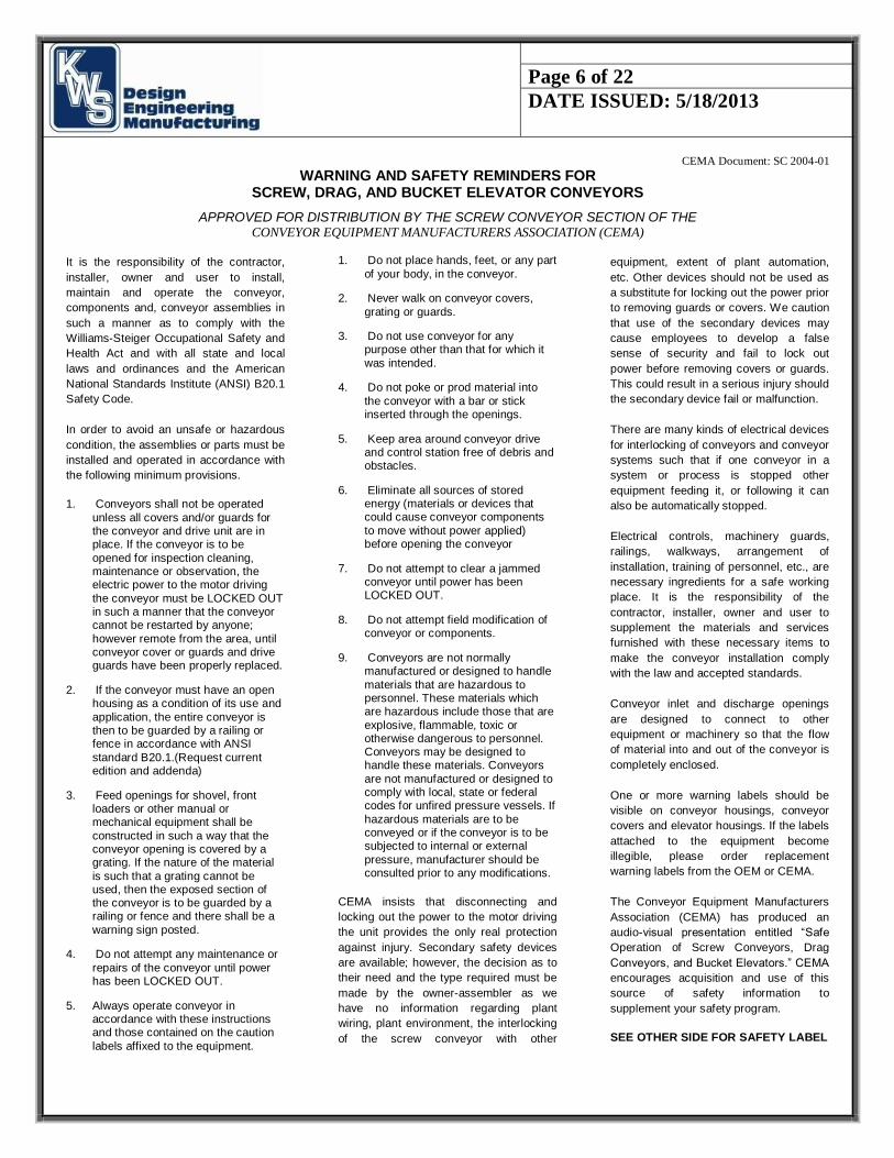
WARNING AND SAFETY REMINDERS FOR SCREW, DRAG, AND BUCKET ELEVATOR CONVEYORS
APPROVED FOR DISTRIBUTION BY THE SCREW CONVEYOR SECTION OF THE CONVEYOR EQUIPMENT MANUFACTURERS ASSOCIATION (CEMA)
It is the responsibility of the contractor,
installer, owner and user to install,
maintain and operate the conveyor,
components and, conveyor assemblies in
such a manner as to comply with the
Williams-Steiger Occupational Safety and
Health Act and with all state and local
laws and ordinances and the American
National Standards Institute (ANSI) B20.1
Safety Code.
In order to avoid an unsafe or hazardous
condition, the assemblies or parts must be
installed and operated in accordance with
the following minimum provisions.
1. Conveyors shall not be operated
unless all covers and/or guards for the conveyor and drive unit are in place. If the conveyor is to be
opened for inspection cleaning, maintenance or observation, the electric power to the motor driving
the conveyor must be LOCKED OUT in such a manner that the conveyor cannot be restarted by anyone;
however remote from the area, until conveyor cover or guards and drive guards have been properly replaced.
2. If the conveyor must have an open housing as a condition of its use and
application, the entire conveyor is then to be guarded by a railing or fence in accordance with ANSI
standard B20.1.(Request current edition and addenda)
3. Feed openings for shovel, front loaders or other manual or mechanical equipment shall be
constructed in such a way that the conveyor opening is covered by a grating. If the nature of the material
is such that a grating cannot be used, then the exposed section of the conveyor is to be guarded by a railing or fence and there shall be a
warning sign posted.
4. Do not attempt any maintenance or
repairs of the conveyor until power has been LOCKED OUT.
5. Always operate conveyor in accordance with these instructions and those contained on the caution
labels affixed to the equipment.
1. Do not place hands, feet, or any part
of your body, in the conveyor.
2. Never walk on conveyor covers,
grating or guards.
3. Do not use conveyor for any purpose other than that for which it
was intended.
4. Do not poke or prod material into
the conveyor with a bar or stick inserted through the openings.
5. Keep area around conveyor drive and control station free of debris and obstacles.
6. Eliminate all sources of stored energy (materials or devices that could cause conveyor components
to move without power applied) before opening the conveyor
7. Do not attempt to clear a jammed conveyor until power has been LOCKED OUT.
8. Do not attempt field modification of conveyor or components.
9. Conveyors are not normally manufactured or designed to handle
materials that are hazardous to personnel. These materials which are hazardous include those that are
explosive, flammable, toxic or otherwise dangerous to personnel. Conveyors may be designed to handle these materials. Conveyors
are not manufactured or designed to comply with local, state or federal codes for unfired pressure vessels. If
hazardous materials are to be conveyed or if the conveyor is to be subjected to internal or external
pressure, manufacturer should be consulted prior to any modifications.
CEMA insists that disconnecting and
locking out the power to the motor driving
the unit provides the only real protection
against injury. Secondary safety devices
are available; however, the decision as to
their need and the type required must be
made by the owner-assembler as we
have no information regarding plant
wiring, plant environment, the interlocking
of the screw conveyor with other
equipment, extent of plant automation,
etc. Other devices should not be used as
a substitute for locking out the power prior
to removing guards or covers. We caution
that use of the secondary devices may
cause employees to develop a false
sense of security and fail to lock out
power before removing covers or guards.
This could result in a serious injury should
the secondary device fail or malfunction.
There are many kinds of electrical devices
for interlocking of conveyors and conveyor
systems such that if one conveyor in a
system or process is stopped other
equipment feeding it, or following it can
also be automatically stopped.
Electrical controls, machinery guards,
railings, walkways, arrangement of
installation, training of personnel, etc., are
necessary ingredients for a safe working
place. It is the responsibility of the
contractor, installer, owner and user to
supplement the materials and services
furnished with these necessary items to
make the conveyor installation comply
with the law and accepted standards.
Conveyor inlet and discharge openings
are designed to connect to other
equipment or machinery so that the flow
of material into and out of the conveyor is
completely enclosed.
One or more warning labels should be
visible on conveyor housings, conveyor
covers and elevator housings. If the labels
attached to the equipment become
illegible, please order replacement
warning labels from the OEM or CEMA.
The Conveyor Equipment Manufacturers
Association (CEMA) has produced an
audio-visual presentation entitled “Safe
Operation of Screw Conveyors, Drag
Conveyors, and Bucket Elevators.” CEMA
encourages acquisition and use of this
source of safety information to
supplement your safety program.
SEE OTHER SIDE FOR SAFETY LABEL

Page 7 of 22
DATE ISSUED: 5/18/2013
ADDITIONAL SAFETY
Safety must be considered a basic factor in machinery operation at all times. Most accidents are the result of carelessness or negligence. The following safety instructions are basic guidelines and should be considered as minimum provisions. Additional information shall be obtained by the purchaser from other sources including the American society of Mechanical Engineers; Standard ANSI B20.1; Standard ANSI B15.1; Standard ANSI A12.1; Standard ANSI MH4.7; Standard ANSI 2244.1-1982.
It is the responsibility of the contractor, installer, owner and user to install, maintain, and operate the bucket elevator and elevator assemblies manufactured and supplied by KWS Manufacturing Company, Inc., in such a manner as to comply with the Occupational Safety and Health Act (OSHA) and with all state and local laws and ordinances and the American National Standard Institute Safety Code.
PRECAUTIONS:
01. MAINTAIN a safety training and safety equipment operation/maintenance program for all employees. 02. BUCKET ELEVATORS shall not be operated unless the elevator housing completely encloses the elevator moving elements and power transmission guards are in place. If the elevator is to be opened for inspection, cleaning or observation, the motor driving the elevator is to be locked out electrically in such a manner that it cannot be restarted by anyone, however remote from the area, unless the elevator housing has been closed and all other guards are in place. 03. IF THE elevator must have an open housing as a condition of its use and application, the entire elevator is then to be guarded by a railing or fence. 04. RUGGED GRATINGS may be used where necessary. If the distance between the grating and moving elements is less than 4 inches, the grating opening must not exceed 1/2 inch by 2 inch. In all cases, the openings shall be restrictive to keep any part of the body or clothing from coming in contact with moving parts of the equipment. SOLID COVERS should be used at all other points and must be designed and installed so that personnel will not be exposed to accidental contact with any moving parts of the equipment. 05. ALL ROTATING equipment such as drives, gears, shafts and couplings must be guarded by the purchaser/owner as required by applicable laws, standards and good practices. 06. SAFETY DEVICES AND CONTROLS must be purchased and provided by the purchaser/owner as required by applicable laws, standards and good practices. 07. PRACTICE good housekeeping at all times and maintain good lighting around all equipment. 08. KEEP ALL operating personnel advised of the location and operation of all emergency controls and devices. Clear access to these controls and devices must be maintained. 09. FREQUENT INSPECTIONS of the controls and devices, covers, guard, and equipment to insure proper working order and correct positioning. 10. DO NOT walk on elevator hood, gratings or guards. 11. DO NOT poke or prod material in the elevator. 12. DO NOT place hands, feet or any part of the body or clothing in the elevator or opening. 13. DO NOT overload elevator or attempt to use it for other than its intended use. 14. INLET and DISCHARGE openings shall be connected to other equipment in order to completely enclose the moving elements of the elevator. 15. BEFORE POWER is connected to the drive, a pre-startup safety check shall be performed to insure the equipment and area are safe for operation and all guards are in place and secure. 16. BUCKET ELEVATORS are not normally manufactured or designed to handle materials that are hazardous to personnel. These materials which are hazardous include those that are explosive, flammable, toxic or otherwise dangerous to personnel. Elevators may be designed to handle these materials. Elevators are not manufactured or designed to comply with local, state, or federal codes for unfired pressure vessels. If hazardous materials are to be conveyed OR IF the elevator is to be subjected to internal or external pressure, KWS Manufacturing Company, Inc., should be consulted prior to any modifications. 17. ALL EQUIPMENT shall be checked for damage immediately upon arrival DO NOT attempt to install a damaged item. 18. ALL BUCKET elevators manufactured by KWS Manufacturing Company, Inc., have warning labels affixed in many easily seen locations. Additional stickers are available upon request.

Page 8 of 22
DATE ISSUED: 5/18/2013
CONVEYOR EQUIPMENT MANUFACTURERS ASSOCIATION 6724 Lone Oak Blvd., Naples, Florida 34109
239-514-3441
Http://www.cemanet.org
CEMA Safety Labels
The CEMA safety labels shown below should be used on screw conveyors, drag conveyors, and bucket elevators.
Safety labels should be placed on inlets, discharges, troughs, covers, inspection doors & drive guards. See CEMA Safety Label Placement Guidelines on CEMA Web Site: http://www.cemanet.org/safety/guidelines.html
PROMINENTLY DISPLAY THESE
SAFETY LABELS ON INSTALLED
EQUIPMENT
SEE OTHER SIDE FOR SAFETY REMINDERS
Note: Labels alone do not substitute for a thorough
in-plant safety training program centered on the
hazards associated with operating your installed
equipment.
Contact CEMA or Your Equipment Manufacturer for
Replacement Labels

Page 9 of 22
DATE ISSUED: 5/18/2013

Page 10 of 22
DATE ISSUED: 5/18/2013
BUCKET ELEVATOR SAFETY

Page 11 of 22
DATE ISSUED: 5/18/2013
SECTION B – INSTALLATION RECEIVING 1. Screw conveyors may be ordered as individual components with all the assembly operations performed in the field, or assembled completely by the manufacturer, with drawings and bill of materials. 2. Immediately upon receipt all items in the shipment should be checked against shipping papers for shortages and inspected for damage. 3. Items to be inspected include troughs, screws, and covers and drive units. 4. DO NOT ATTEMPT TO INSTALL DAMAGED COMPONENTS OR ASSEMBLIES. LIFTING AND MOVING 1. Extreme care must be taken to prevent damage when moving assembled conveyors or components. 2. Spreader bars with slings are the recommended support method for lifting. 3. Unsupported span should be no greater than 12 feet. 4. NEVER LIFT A CONVEYOR WITH ONLY ONE SUPPORT POINT. 5. Unusually heavy items such as drives or gates shall be considered when choosing support points because of load balance and their bending effect. 6. Shop assembled conveyors are typically match marked and shipped in the longest sections for practical shipment.
Page 12 of 22
DATE ISSUED: 5/18/2013
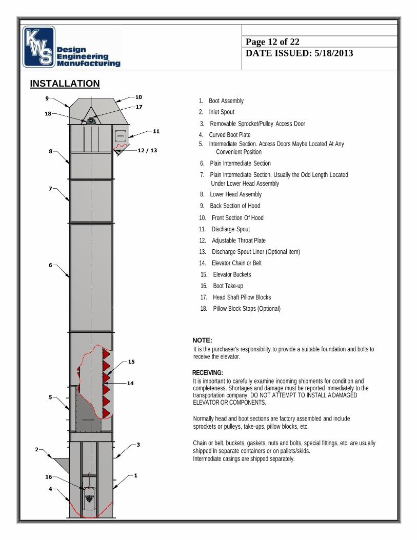
INSTALLATION
1. Boot Assembly
2. Inlet Spout
3. Removable Sprocket/Pulley Access Door
4. Curved Boot Plate
5. Intermediate Section. Access Doors Maybe Located At Any Convenient Position
6. Plain Intermediate Section
7. Plain Intermediate Section. Usually the Odd Length Located
Under Lower Head Assembly
8. Lower Head Assembly
9. Back Section of Hood
10. Front Section Of Hood
11. Discharge Spout
12. Adjustable Throat Plate
13. Discharge Spout Liner (Optional item)
14. Elevator Chain or Belt
15. Elevator Buckets
16. Boot Take-up
17. Head Shaft Pillow Blocks
18. Pillow Block Stops (Optional)
NOTE:
It is the purchaser's responsibility to provide a suitable foundation and bolts to receive the elevator.
RECEIVING:
It is important to carefully examine incoming shipments for condition and completeness. Shortages and damage must be reported immediately to the transportation company. DO NOT ATTEMPT TO INSTALL A DAMAGED ELEVATOR OR COMPONENTS.
Normally head and boot sections are factory assembled and include sprockets or pulleys, take-ups, pillow blocks, etc.
Chain or belt, buckets, gaskets, nuts and bolts, special fittings, etc. are usually shipped in separate containers or on pallets/skids. Intermediate casings are shipped separately.

Page 13 of 22
DATE ISSUED: 5/18/2013
INSTALLATION CONTINUED CASING (All Elevators)
A. Insure that anchor bolts are securely placed and conform to the pattern of the boot section mounting holes. B. Set
boot in place insuring that boot section top flange is level and casing is plumb.
This is accomplished by shimming under the bottom flange. Use shims only next to anchor bolts—not elsewhere along flange.
Any gap resulting from shimming is generally sealed with a strong structural grout.
C. It is essential that the boot be set accurately.
D. Check drawings to determine correct sequence of erecting intermediate casing. Caulk or gasketing (if provided) should be placed between all casing flanges to provide dust tight sealing.
E. Normally the erection crew should build a lifting bracket to avoid distortion to fabricated assemblies.
F. Each and every intermediate section must be level and plumb. It is common to find minor deviations in these types of fabricated assemblies.
Most often they can be corrected by rotating 180° or turning end for end.
If this does not solve an out of level or out of plumb condition it will be necessary to use metal shims and caulk the resulting
gap.
When a gap occurs in a corner of the casing, metal shims should be used and should extend a minimum of six inches in both directions. Insure that shims do not project inside of casing.
Each intermediate section must be plumbed to less than 1/8" deviation before proceeding to the next section. Casings must be braced or anchored to a rigid structure every 20 ft. and not more than 4 ft. below the head section. If a rigid structure is not available, guy wires may be used with the same spacing.
G. After all intermediate sections are correctly placed, remove the front and back sections of the hood and set the lower head using the same procedures as with the intermediate sections. Replace hood sections after performing all installation steps H thru PC or PB.
H. It is critical that the head shaft be exactly level. Minor pillow block shimming may be necessary. Check head shaft pillow block set
screws for tightness.
MACHINERY (Chain Type)
1C. Remove boot sprocket access door.
Drop plumb line from head end sprocket to boot sprocket. Insure that sprockets are centered in casing and are exactly in line with each other.
When erecting a double strand chain elevator, check factory drawings for correct sprocket spacing. Checks to insure that the sprocket set
screws are tight. Sprockets should be in line when viewed from the narrow side of the casing. Head and boot shafts
are generally offset when viewed from the wide dimension of the casing. Check factory drawings for offset. Double strand chain elevators
commonly will have no offset as identical sprockets are used at the head and boot sections.
JC. Move boot take-up to its uppermost position (head end take-up to lowest position.) Make these adjustments uniformly to both sides at the same time. Many bearings will not accommodate much misalignment. Severe damage to internal bearing parts and seals can occur if this procedure is not followed.
KC. Depending on lifting equipment and access available, the chains and buckets can be preassembled or installed in 10 ft. sections of chain with buckets to be attached later.
When installing offset side bar chain, insure that the widest part of the side bar (open end) points in the direction of chain travel. Use care not
to get a side twist in the chain during handling. LC. It may be necessary to remove up to several links of chain during initial installation.
Page 14 of 22
DATE ISSUED: 5/18/2013
INSTALLATION CONTINUED
CASING (All Elevators)
A. Insure that anchor bolts are securely placed and conform to the pattern of the boot section mounting holes. B. Set
boot in place insuring that boot section top flange is level and casing is plumb.
This is accomplished by shimming under the bottom flange. Use shims only next to anchor bolts—not elsewhere along flange.
Any gap resulting from shimming is generally sealed with a strong structural grout.
C. It is essential that the boot be set accurately.
D. Check drawings to determine correct sequence of erecting intermediate casing. Caulk or gasketing (if provided) should be placed between all casing flanges to provide dust tight sealing.
E. Normally the erection crew should build a lifting bracket to avoid distortion to fabricated assemblies.
F. Each and every intermediate section must be level and plumb. It is common to find minor deviations in these types of fabricate ed assemblies.
Most often they can be corrected by rotating 180° or turning end for end.
If this does not solve an out of level or out of plumb condition it will be necessary to use metal shims and caulk the resulting
gap.
When a gap occurs in a corner of the casing, metal shims should be used and should extend a minimum of six inches in both directions. Insure that shims do not project inside of casing.
Each intermediate section must be plumbed to less than 1/8" deviation before proceeding to the next section. Casings must be braced or anchored to a rigid structure every 20 ft. and not more than 4 ft. below the head section. If a rigid structure is not available, guy wires may be used with the same spacing.
G. After all intermediate sections are correctly placed, remove the front and back sections of the hood and set the lower head using the same procedures as with the intermediate sections. Replace hood sections after performing all installation steps H thru PC or PB.
H. It is critical that the head shaft be exactly level. Minor pillow block shimming may be necessary. Check head shaft pillow block set screws for tightness.
MACHINERY (Belt Type)
IB. Remove boot pulley access door.
Drop a plumb line from head end pulley to boot pulley.
Insure that pulleys are centered in casing and are exactly in line with each other. Check
to insure that the pulley set screws are tight.
Pulleys should be in line when viewed from the narrow side of the casing.
Head and boot shafts are generally offset when viewed from the wide dimension of the casing. Check
factory drawings for offset.
Page 15 of 22
DATE ISSUED: 5/18/2013
INSTALLATION CONTINUED
MC. Adjust take-up accordingly to provide 1/8" to 1/4" gap between the chain barrel and root of boot sprocket tooth. This gap should
occur at 6 o'clock on the boot sprocket.
The gap is to accommodate chorda! action of the chain. On long pitch chain this gap can be increased
accordingly. Adjust bibb to provide up to 3/4" to 1" clearance to buckets. NC. At this point you may
find it desirable to "run in" the chain for a period of several hours.
OC. Install buckets using bolts, nuts and lock washers provided. It is a good idea to peen the bolt threads after the buckets are securely in place.
If plastic buckets are being installed, use care to avoid over tightening. Steel backups may be required. PC.
Adjust bibb to provide 3/4" to 1" clearance to buckets. Install upper hood front and back sections.
QC. After satisfactory alignment and trial operation, weld stops at each end of head shaft pillow blocks to prevent bearing movement. Stops may be of angle iron channels, key stock, etc.
NOTES (Chain Type)
AA. If elevator is equipped with gravity type take-up, use a come along or other means to raise takeup box to the upper most portion when coupling the chain together.
Add weight (concrete or steel stampings) to weigh box as required for smooth operation. Weight must be uniformly distributed in weight box.
Boot sprockets will fully engage the chain, however, insure that upward movement is available to accommodate chordal action of chain. Usually 2 to 3 inches is adequate.
BB. When installing double strand chain elevators be sure to lay out chains and verify equal lengths of parallel strands.
Double strand chains are usually matched and tagged left and right.
CC. On double strand elevators, one boot sprocket is keyed to the shaft, the other sprocket floats between shaft collars. Insure that these collars are tight.
Check shaft collars frequently for tightness. After all plumbing and other adjustments are made, it may be necessary to drill a set screw indent into boot shaft to hold shaft collar position.
DD. During normal operations, avoid starting and stopping any elevator when loaded with material.
EE. If elevator components are to be stored at the job site for some time prior to erection, insure that components are protected from elements.
It is not advisable to cover elevator components tightly with polyethylene. Condensation will collect and cause corrosion and premature motor failure.
FF. If elevator is to be erected but not used for a long period of time, it is advisable to run the elevator at least one hour per week. MACHINERY (Belt Type)
IB. Remove boot pulley access door.
Drop a plumb line from head end pulley to boot pulley.
Insure that pulleys are centered in casing and are exactly in line with each other. Check
to insure that the pulley set screws are tight.
Pulleys should be in line when viewed from the narrow side of the casing.
Head and boot shafts are generally offset when viewed from the wide dimension of the casing. Check
factory drawings for offset
Page 16 of 22
DATE ISSUED: 5/18/2013
INSTALLATION CONTINUED JB. Move boot take-up to its uppermost position (head end take-up to lowest position.) Make these adjustments
uniformly to both sides at the same time. Many bearings will not accommodate much misalignment. Severe damage to internal bearing parts and seals can occur if this procedure is not followed.
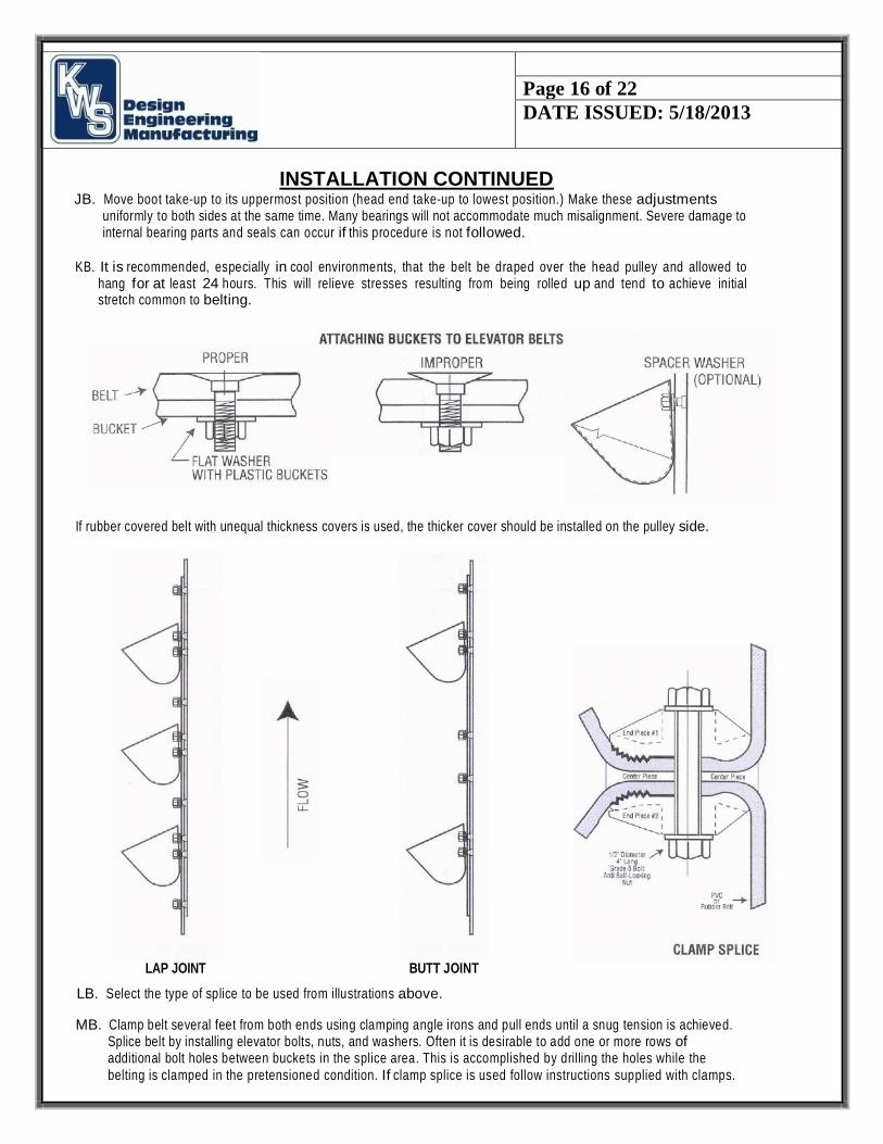
KB. It is recommended, especially in cool environments, that the belt be draped over the head pulley and allowed to
hang for at least 24 hours. This will relieve stresses resulting from being rolled up and tend to achieve initial stretch common to belting.
If rubber covered belt with unequal thickness covers is used, the thicker cover should be installed on the pulley side.
LAP JOINT BUTT JOINT
LB. Select the type of splice to be used from illustrations above.
MB. Clamp belt several feet from both ends using clamping angle irons and pull ends until a snug tension is achieved. Splice belt by installing elevator bolts, nuts, and washers. Often it is desirable to add one or more rows of additional bolt holes between buckets in the splice area. This is accomplished by drilling the holes while the belting is clamped in the pretensioned condition. If clamp splice is used follow instructions supplied with clamps.
Page 17 of 22
DATE ISSUED: 5/18/2013
INSTALLATION CONTINUED
NB. Remove belt clamps and adjust take-ups uniformly to both sides to remove any slack in the belt. Use caution to avoid over
tightening the belt as this can cause premature failure of: Belting, shafts, bearings, etc. At this point it is advisable to "run in" the belt for a period of several hours to observe belt tracking and any further initial stretch.
The responsibility to do the splice correctly lies with the installer.
OB. Install buckets using bolts, nuts and lock washers provided. It is a good idea to peen the bolt threads after the buckets are securely in place.
If plastic buckets are being installed, use care to avoid over tightening. Large diameter steel flat washers or fender washers are frequently used with plastic buckets.
PB. Adjust bibb to provide up to 3/4" to 1" clearance to buckets. Install upper hood front and back section.
QB. After satisfactory alignment and trial operation, weld stops at each end of head shaft pillow blocks to prevent bearing movement. Stops can be angle iron, channels, keystock material, etc.
NOTES (Belt Type)
AA. If elevator is equipped with gravity take-up, use a come-along or other means to raise take- up box to the upper most position when splicing the belt.
Add weight (concrete or steel stampings) to weight box as required for smooth operation. Weight must be uniformly distributed in weight box and sufficient to remove slack from belt.
BB. During normal operations, avoid starting and stopping any elevator when loaded with material.
CC. If elevator components are to be stored at the job site for a period of time prior to erection, insure that components are pro- tected from the elements.
It is not advisable to cover elevator components tightly with polyethylene. Condensation will collect and cause corrosion to elevator components and possibly premature motor failure due to moisture in the windings.
DD. If elevator is to be erected but not used for a long period of time, it is least one hour per week.
DRIVES (All Types)
If drive is not factory assembled, install at this time.
1. Gearmotor Drive
Mount driven sprocket securely to head shaft.
Fill reducer with proper lubricant and install driver sprocket. Recommended oil is generally indicated on the reducer name tags.
Set reducer in position and line up drive
sprockets. Shorten center distance by adjusting
movable base. Install chain and connecting links.
Adjust slide base to a point where some sag is noted on the bottom strand of chain when the top strand is tight.
Lock base of reducer into position. Check all mounting bolts for tightness.
Install chain guard and add lubricant if oil bath guard is furnished.
If possible, rotate gearmotor by hand to determine whether the back stop is correctly installed. (See reducer
manufacturer’s instructions for additional details.)
Other types of backstops are frequently used. (See manufacturer’s instructions.)
2. Shaft Mounted Gear Reducers
Assemble back stop to reducer. (See manufacturer’s instructions.) Assemble reducer to head shaft using bushings and keys if provided.
Page 18 of 22
DATE ISSUED: 5/18/2013
SECTION C– OPERATION
START UP (All Types)
Check to insure elevator is free of foreign materials before connecting power.
Check to insure all guards, covers, safety devices and controls are in place and operating correctly.
Initial start up of elevator should commence with several short jogs gradually lengthening in duration without material.
Check take-up adjustment after 8 hours.Re-tighten all fasteners. Check and realign sprockets/pulleys as necessary. Gradually
begin feeding material to the elevator. Increase feed rate slowly until reaching design capacity. Empty elevator. LOCK OUT
ALL POWER. Check for loose fasteners. Check alignment of sprockets/pulleys.
Elevator should be checked for loose fasteners and alignment at least once a month.
OPERATION (Chain Type)
When elevator is new it is common to have an occasional tight chain joint. This will cause some vibration but will eventually loosen. If
plastic buckets are used in conjunction with metal breaker buckets, it is normal to experience some pulsation.
Characteristics of the material will affect the degree of pulsation. Pulsation is caused by the difference in bucket projection.
Do not intermix old chain and new chain in parallel strands. Always order matched lengths.
Primary to satisfactory elevator operation is uniform material feed rates—not surge loading and excessive boot flooding.
When consulting the factory regarding a specific elevator, refer to the purchase order number, year of manufacture if known, and
equipment number if appropriate.
Regular inspection and maintenance will insure uninterrupted and satisfactory elevator performance.
OPERATION (Belt Type)
If plastic buckets are used in conjunction with metal breaker buckets, it is normal to experience some pulsation. Characteristics of the
material will affect the degree of pulsation. Pulsation is caused by the difference in bucket projection.
Primary to satisfactory elevator operation is uniform material feed rates—not surge loading and excessive boot flooding. Regular
inspection and maintenance will insure uninterrupted and satisfactory elevator performance.
When consulting the factory regarding a specific elevator, refer to the purchase order number, year of manufacture if known, and
equipment number if appropriate.

Page 19 of 22
DATE ISSUED: 5/18/2013
OPERATION CONTINUED
START UP (All Types)
Check to insure elevator is free of foreign materials before connecting power.
Check to insure all guards, covers, safety devices and controls are in place and operating correctly.
Initial start up of elevator should commence with several short jogs gradually lengthening in duration without material.
Check take-up adjustment after 8 hours re-tighten all fasteners. Check and realign sprockets/pulleys as necessary. Gradually
begin feeding material to the elevator. Increase feed rate slowly until reaching design capacity. Empty elevator. LOCK OUT
ALL POWER. Check for loose fasteners. Check alignment of sprockets/pulleys.
Elevator should be checked for loose fasteners and alignment at least once a month.
OPERATION (Belt Type)
If plastic buckets are used in conjunction with metal breaker buckets, it is normal to experience some pulsation. Characteristics of the
material will affect the degree of pulsation. Pulsation is caused by the difference in bucket projection.
Primary to satisfactory elevator operation is uniform material feed rates—not surge loading and excessive boot flooding. Regular
inspection and maintenance will insure uninterrupted and satisfactory elevator performance.
When consulting the factory regarding a specific elevator, refer to the purchase order number, year of manufacture if known, and
equipment number if appropriate.

Page 20 of 22
DATE ISSUED: 5/18/2013
OPERATION CONTINUED
PROBLEM
Elevator
Vibrates
POSSIBLE CAUSE
1. Foreign matter in boot
2. Excessively tight chain/belt
3. Excessively loose chain/belt
4. Loose or broken buckets
5. Buckets hitting bibb plate
6. Misaligned elevator head and boot shaft
7. Elevator is not adequately braced. See para. F,
installation
8. Chain/belt hitting inside of casing when casing is not
plumb
Elevator Will Not Start
1. Obstruction in boot
2. Electrical problem
3. Backstop incorrectly installed
4. Broken V-Beits or drive chains
5. Reducer failure
6. Boot excessively plugged with material
7. Excessively tight chain/belt
Pillow Blocks Get Hot
Elevator Not Discharging Properly
1. Over lubrication
2. Under lubrication
3. Excessive chain/belt tension
4. Misalignment of head shaft pillow blocks
5. Misalignment between head and boot shaft
1. Speed incorrect - consult factory
2. Air cushion - vent compartment being discharged into
3. Light fluffy materials - reduce speed up to 15%
4. Certain materials may require perforated
buckets*
5. Some materials may be affected by static
electricity
*Consult Factory

Page 21 of 22
DATE ISSUED: 5/18/2013
SECTION D - MAINTANENCE
Periodic inspections must be performed to determine the wear rate of all chains, buckets, belts and bearings. During these inspections the alignment of
sprockets, pulleys and all drive components shall be checked. Retightening of fasteners and checks to insure guards, covers, gratings, contrails, and safety
devices are in place, secure, and operating correctly.
Keep a good supply of spare parts. When ordering, refer to our Service Manual and furnish the part identification as well as original order number.
WARNING: Removal of backstop may cause unexpected machinery movement as indicated by note 17 of "Safety" If backstop is installed as part of
shaft mount reducer removal of torque arm may also cause unexpected machinery movement.

Page 22 of 22
DATE ISSUED: 5/18/2013
CHART A – BOLT TORQUE GUIDE
GENERAL BOLT TIGHTENING TORQUE (Ft. lbs.)
Bolt Dia. (inches)
Threads Per Inch (UNC)
SAE 2 SAE 5 SAE 8 18-8 & 316
STAINLESS STEEL
1/4 20 5 9 12 6
5/16 18 11 18 25 11
3/8 16 18 31 44 20
7/16 14 28 49 69 29
1/2 13 44 73 105 40
9/16 12 63 108 149 52
5/8 11 96 147 212 86
3/4 10 158 252 351 115
7/8 9 219 389 552 180
1 8 316 589 784 240
The reason all applications should be evaluated to determine the optimum tightening
torque is that the K factor in the formula is always an estimate. The most commonly used K factors are 0.20 for plain finished bolts.
Formula: T= K x D x P
• T Target tighten torque (the result of this formula is in inch pounds, dividing
by 12 yields foot pounds)
• K Coefficient of friction (nut factor), always an estimation in this formula
• D Bolts nominal diameter in inches
• P Bolt's desired tensile load in pounds (generally 75% of yield strength)
[P(lbs) = (75%) Yield Strength * Tensile Stress Area]
The above Bolt Torque Guide is for fasteners used to assemble screw conveyors and does not
include coupling bolts. Over tightening of coupling bolts could result in failure in tension. CEMA recommends tightening coupling bolts to 75-percent of the values given in the Bolt Torque Guide to
eliminate over tightening of coupling bolts


