Page 1
BUCKLING AND POST BUCKLING OF
STRUCTURAL COMPONENTS
by
SHRUTI DESHPANDE
Presented to the Faculty of the Graduate School of
The University of Texas at Arlington in Partial Fulfillment
of the Requirements
for the Degree of
MASTER OF SCIENCE IN MECHANICAL ENGINEERING
THE UNIVERSITY OF TEXAS AT ARLINGTON
December 2010
Page 2
Copyright © by Shruti Deshpande 2010
All Rights Reserved
Page 3
iii
ACKNOWLEDGEMENTS
I am sincerely grateful to my thesis advisor Dr. Kent Lawrence, for his valuable
guidance and support throughout this thesis. He has consistently helped me improve and
supported me to gain my accomplishments. The requirements of this thesis were achieved in a
timely and organized manner under his guidance. Without him the entire work would be a
reckless venture.
I would like to thank Dr. B. P. Wang and Dr. Seiichi Nomura for taking the time to serve
on my thesis committee.
I am indebted to my family and especially to my husband Chinmay for his continuous
support and encouragement in all my endeavors. My Master’s degree wouldn’t have been
possible without him. I also thank all my friends, especially my roommates Athena and Rasika
who were a great source of encouragement.
November 23, 2010
Page 4
iv
ABSTRACT
BUCKLING AND POST BUCKLING OF
STRUCTURAL COMPONENTS
Shruti Deshpande, M. S.
The University of Texas at Arlington, 2010
Supervising Professor: Kent Lawrence
Structural members and components, such as shells and trusses of different
geometries, form the intricate and deep seated parts in the manufacturing of missiles
submarines, rockets, airplanes, automobiles etc and find applications in civil structures such as
bridges. These members are comprised of components like conical frusta, cylindrical panels
and shallow trusses. In many cases, the sole purpose of such shell structures is to absorb the
energy generated due to impact which means, that these structures are subjected to heavy
loads and can experience failure due to buckling.
The objective of this work is to study the buckling and post buckling behavior of such
members. The study is carried out using finite element analysis. The widely implemented
softwares ANSYS APDL and ANSYS Workbench are used to perform the analysis.
The components analyzed consist of shell structures such as conical frusta and
cylindrical panels, and other structures like the shallow truss, diagonal truss and the shallow
arch. These structures are analyzed for their buckling and post buckling behavior when subject
to specific loading conditions and geometric, contact and material non-linearity. The results
compare favorably with known solutions.
Page 5
v
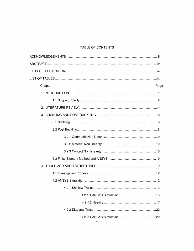
TABLE OF CONTENTS
ACKNOWLEDGEMENTS ....................................................................................................... iii
ABSTRACT ............................................................................................................................. iv
LIST OF ILLUSTRATIONS..................................................................................................... vii
LIST OF TABLES .................................................................................................................... ix
Chapter Page
1. INTRODUCTION……………………………………..………..….. .............................1
1.1 Scope of Study.........................................................................................2
2. LITERATURE REVIEW..........................................................................................4
3. BUCKLING AND POST BUCKLING......................................................................8
3.1 Buckling....................................................................................................8
3.2 Post Buckling............................................................................................8
3.2.1 Geometric Non linearity............................................................9
3.2.2 Material Non linearity .............................................................10
3.2.3 Contact Non linearity..............................................................10
3.3 Finite Element Method and ANSYS.......................................................10
4. TRUSS AND ARCH STRUCTURES....................................................................12
4.1 Investigation Process .............................................................................12
4.2 ANSYS Simulation .................................................................................12
4.2.1 Shallow Truss.........................................................................13
4.2.1.1 ANSYS Simulation ..........................................13
4.2.1.2 Results............................................................17
4.2.2 Diagonal Truss .......................................................................22
4.2.2.1 ANSYS Simulation ..........................................22
Page 6
vi
4.2.2.2 Results.............................................................25
4.2.3 Shallow Arch ..........................................................................27
4.2.3.1 ANSYS Simulation ..........................................27
4.2.3.2 Results............................................................29
5. SHELL STRUCTURES ........................................................................................32
5.1 Cylindrical Panel .......................................................................32
5.1.1 ANSYS Simulation .............................................32
5.1.2 Results...............................................................35
5.2 Conical Frustum ........................................................................38
5.2.1 ANSYS Simulation .............................................38
5.2.2 Results...............................................................41
5.3 Eigen Value Buckling Load .......................................................44
6. CONCLUSIONS AND RECOMMENDATIONS....................................................46
APPENDIX A. DEFORMED SPECIMES OF CONICAL FRUSTA............................47
APPENDIX B. EIGEN VALUE BUCKLING MODE SHAPES....................................50
REFERENCES.......................................................................................................................54
BIOGRAPHICAL INFORMATION ..........................................................................................56
Page 7
vii
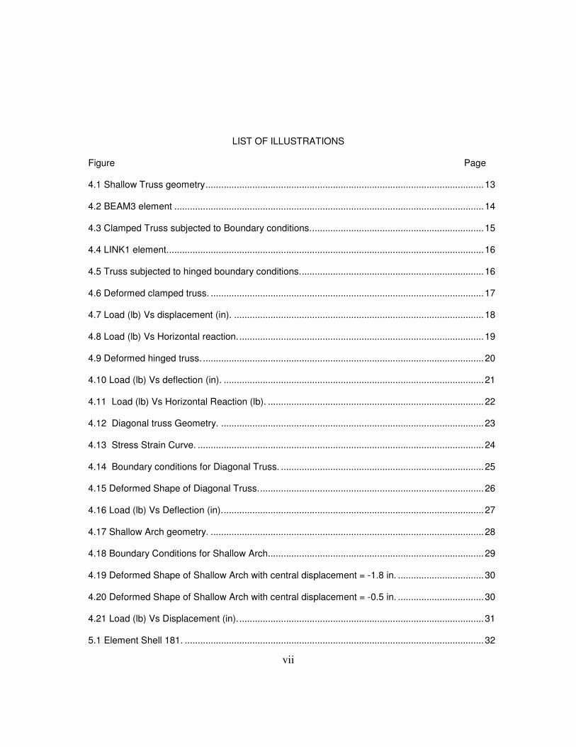
LIST OF ILLUSTRATIONS
Figure Page 4.1 Shallow Truss geometry...........................................................................................................13
4.2 BEAM3 element .......................................................................................................................14
4.3 Clamped Truss subjected to Boundary conditions...................................................................15
4.4 LINK1 element..........................................................................................................................16
4.5 Truss subjected to hinged boundary conditions.......................................................................16
4.6 Deformed clamped truss. .........................................................................................................17
4.7 Load (lb) Vs displacement (in). ................................................................................................18
4.8 Load (lb) Vs Horizontal reaction...............................................................................................19
4.9 Deformed hinged truss. ............................................................................................................20
4.10 Load (lb) Vs deflection (in). ....................................................................................................21
4.11 Load (lb) Vs Horizontal Reaction (lb). ...................................................................................22
4.12 Diagonal truss Geometry. .....................................................................................................23
4.13 Stress Strain Curve. ..............................................................................................................24
4.14 Boundary conditions for Diagonal Truss. ..............................................................................25
4.15 Deformed Shape of Diagonal Truss.......................................................................................26
4.16 Load (lb) Vs Deflection (in).....................................................................................................27
4.17 Shallow Arch geometry. .........................................................................................................28
4.18 Boundary Conditions for Shallow Arch...................................................................................29
4.19 Deformed Shape of Shallow Arch with central displacement = -1.8 in. .................................30
4.20 Deformed Shape of Shallow Arch with central displacement = -0.5 in. .................................30
4.21 Load (lb) Vs Displacement (in)...............................................................................................31
5.1 Element Shell 181. ...................................................................................................................32
Page 8
viii
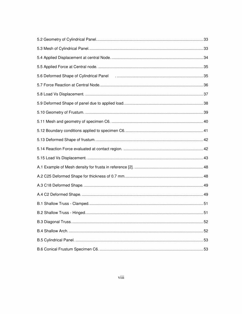
5.2 Geometry of Cylindrical Panel..................................................................................................33
5.3 Mesh of Cylindrical Panel.........................................................................................................33
5.4 Applied Displacement at central Node. ....................................................................................34
5.5 Applied Force at Central node. ................................................................................................35
5.6 Deformed Shape of Cylindrical Panel . ...............................................................................35
5.7 Force Reaction at Central Node...............................................................................................36
5.8 Load Vs Displacement. ............................................................................................................37
5.9 Deformed Shape of panel due to applied load.........................................................................38
5.10 Geometry of Frustum. ............................................................................................................39
5.11 Mesh and geometry of specimen C6. ....................................................................................40
5.12 Boundary conditions applied to specimen C6........................................................................41
5.13 Deformed Shape of frustum. ..................................................................................................42
5.14 Reaction Force evaluated at contact region. .........................................................................42
5.15 Load Vs Displacement. ..........................................................................................................43
A.1 Example of Mesh density for frusta in reference [2]. ...............................................................48
A.2 C25 Deformed Shape for thickness of 0.7 mm........................................................................48
A.3 C18 Deformed Shape. .............................................................................................................49
A.4 C2 Deformed Shape. ...............................................................................................................49
B.1 Shallow Truss - Clamped.........................................................................................................51
B.2 Shallow Truss - Hinged............................................................................................................51
B.3 Diagonal Truss.........................................................................................................................52
B.4 Shallow Arch. ...........................................................................................................................52
B.5 Cylindrical Panel. .....................................................................................................................53
B.6 Conical Frustum Specimen C6. ...............................................................................................53
Page 9
ix
LIST OF TABLES
Table Page 4.1 Dimensions of Shallow Truss...................................................................................................14
4.2 Material Properties for Shallow Truss. .....................................................................................14
4.3 Diagonal Truss Dimensions. ....................................................................................................23
4.4 Material Properties for Diagonal Truss.....................................................................................24
4.5 Dimensions of Shallow Arch. ...................................................................................................27
4.6 Material Properties of Shallow Arch. ........................................................................................28
5.1 Dimensions of Panel. ...............................................................................................................32
5.2 Material Properties of panel. ....................................................................................................34
5.3 Dimensions of Conical frusta. ..................................................................................................40
5.4 Material Properties of Frusta....................................................................................................41
5.5 Material Properties of Rigid Plate.............................................................................................42
5.6 Force Values for Frusta............................................................................................................44
5.7 Eigen Value Buckling Load compared to the Non-linear Buckling Limit Load. ........................45
Page 10
1
CHAPTER 1
INTRODUCTION
The current manufacturing industry emphasizes on the use of structural members,
which encompass light weight with high strength and are expected to absorb high energy and
carry heavy loads. These members are comprised of Shell structures and shallow trusses.
The shell structures have a significant advantage in regards to load carrying capacity.
When load is applied to a shell it results into different types of internal forces which can cause
bending, twisting, transverse shearing and buckling. Commonly used components are
cylindrical panels, cylindrical and spherical shells and conical frusta. In many cases, these shell
structures are the deep seated structures in manufacturing submarines, missiles, tanks and
their roofs and fluid reservoirs. These components act as energy absorbers in most of these
cases.
These energy absorbing devices may be classified on the basis of the following
principles,
- extrusion
- friction
- material deformation
Shell structures such as cylindrical tubes and conical frusta are the most frequently
used devices that absorb energy by material deformation. Such axis-symmetric shell structures
are widely implemented in aircraft and spacecraft structures, nuclear reactors, storage tanks for
bulk solids and liquids, pressure vessels, pipelines etc.. Conical shells also find applications in
marine engineering. These are mainly implemented as transition elements beween cylinders of
different diameters. Shell structures also find versatile applications in the field of civil
Page 11
2
engineering. Some examples that have thin shells as structural components are silos, roofs,
container, tanks, pipes, pressure vessels, submarines and aircraft wings.
Structural Members such as Shallow Truss and arch find many applications in the field
of civil engineering. These form an important part of various structures like air plane hangars,
bridges, railways, roof structures etc. Arches are used for underground structures such as
drains and vaults and are widely used structural members in bridges and buildings too. The
arch can carry a much greater load thus making it more significant.
Buckling of these kind of structures is dependent on various number of variables like
geometry, material properties and the applied load. The Finite element methods (FEM)
technique is extensively used to analyze the buckling and post bucking behavior of such
structural components. Several finite element softwares like ADINA, NASTRAN, ANSYS and
ABAQUS are implemented for buckling and post bucking analysis.
Several papers that study the theories of the collapse of shell and truss structures have
appeared in the literature. The buckling analysis of such structures using finite element methods
occurs in the literature.
1.2 Scope of Study
The focus of this thesis is the study of buckling and post buckling of structural
components using ANSYS APDL and ANSYS Workbench. The thesis will discuss a number of
components and structural members such as The Shallow Arch, Shallow Truss, Diagonal Truss,
Cylindrical Panel and Conical Frusta.
The entire work area comprised of a number of chapters. For conducting the analysis
an intense literature review on the buckling analysis of thin shells like cylindrical shells, conical
shells, cylindrical panels and trusses is conducted, which is briefed in the second chapter. A
brief review of the buckling and post buckling concept is presented in the third chapter. The
fourth chapter details about the analysis of Shallow truss, Diagonal truss and the shallow arch
for buckling and post buckling behavior using a finite element methods software, ANSYS APDL.
The fifth chapter details about the buckling and post buckling analysis of the shells, such as the
Page 12
3
cylindrical panel and the conical frustum using the finite element methods software ANSYS
Workbench. A study of Eigen value buckling for all the cases is also included in the fifth chapter.
This is followed by conclusion and recommendation in the sixth chapter and then the references
used for the entire achievement.
Page 13
4
CHAPTER 2
LITERATURE REVIEW
S Aghajari, K Abedi and H Showkati have studied the Buckling and post-buckling
behavior of thin walled cylindrical steel shells with varying thickness subjected to uniform
external pressure [1].
For the experimental study, four different cylindrical shell specimens with
varying thickness were tested to collapse. To study the buckling and post buckling of these
structures using ANSYS which is a finite element modeling software, material and geometric
non linearities were considered in the analysis performed. Shell elements with large deflection,
stress stiffening and non linear capabilities were used to model the cylindrical shells. From
obtained results, it was observed that the buckling load obtained using ANSYS was higher than
that obtained experimentally, though the percentage difference was less.
Thus, the study shows that the numerical behavior predicted by the non linear
finite element collapse analysis is close to the experimental results. Consequently, finite
element modeling is found to be reliable enough to be used to perform non linear analysis for
the study of buckling and post buckling behavior.
N. K. Gupta, N. Mohamed Sheriff, R. Velmurugan have studied the buckling of thin
conical frustum under axial loads [2]. They performed experiments with certain specimens of
conical frusta. The non1 linear material used for these specimens was Aluminum. Experiments
were performed by subjecting the conical shells to quasi static loading. Axial compression of the
shells was carried out by compressing each specimen between two rigid platens. The load
deflection curves were obtained from these experiments were compared with the results
obtained from numerical analysis.
The compressive failure mode was simulated using ANSYS. Material, geometric and
contact non linearity were included. The material non-linearity was included using the actual
Page 14
5
stress strain curve obtained from the experiments. The results thus obtained were higher but
could be compared well with the experimental ones. Using finite elements modeling thus
facilitates the analysis of intermediate stages of buckling which reduces the cost and time.
A.Pica and R. D. Wood have studied the post buckling behavior of plates and shells
using a mindlin shallow shell formulation[3]. This paper presents a geometrically non-linear
analysis of shallow shells using finite element mindlin formulation. It gives results for post
buckling behavior of square and circular plates subject to direct in plane loading and square
plate subject to in plane shear loading. Analysis of shallow truss and cylindrical and spherical
shells are also presented, all exhibiting snap through behavior. For a number of post buckling
solutions the 9 node lagrangian element was used which demonstrates the ability to model
curved boundaries.
Chawalit Thinvongpituk and Pisit Techarungpaisarn have studied the Buckling of Axially
compressed conical shells of linearly variable thickness using structural model[4]. The study
was conducted with a series of experiments performed using conical specimens with constant
thickness, which were crushed till the buckling load was recorded. For comparison FE model
was constructed using ABAQUS to simulate the experiment. The buckling loads obtained from
the experiment and the FE model were observed to be in good agreement with each other. The
FE model was further used to investigate the cone with non constant thickness.
It was observed that variation of thickness in axial direction results in the reduction of
buckling load. The reduction of buckling load, due to the small thickness variation in axial
direction is proportional to the thickness variation parameter ε, where ε is the ratio of the
difference of minimum and maximum wall thickness to the minimum wall thickness of cone.
Huu Tai Thai and Seung Eock Kim have performed the Inelastic post buckling analysis
of space steel trusses using the generalized displacement control method[5]. Space steel
trusses used extensively for domes or roofs. In this paper the authors have extended the
application of Hill [11] model for inelastic post buckling analysis of space steel trusses.
Geometric and material non linearity are considered for the study.
Page 15
6
This paper presents an algorithm that can trace the equilibrium paths of the non linear
problem with multiple limit points and snap back points. A computer program is developed to
predict the inelastic post buckling behavior of space truss structures. The paper includes a
number of examples solved to prove the accuracy of the proposed procedure.
A.B. Sabir and A. C. Lock have studied the application of Finite Element
Methods to the Large Deflection Geometrically Non Linear behavior of Cylindrical Shells[9]. The
paper presents a method that is capable of dealing with the study of post buckling of structures
subjected to in plane and lateral loading. It employs linearized incremental method and Newton
Raphson method.
The algorithm based on the linearized incremental and Newton Raphson
methods, has been used on cylindrical shells subjected to lateral loading and a flat plate
subjected to in plane loading. A family of shells of similar dimensions but varying thickness has
been examined and load deflection curves exhibiting complicated behavior are obtained.
H Ramsey has studied the plastic buckling of conical shells under axial compression
[6]. This research paper presents analysis and experimental results of plastic axisymmetric
buckling of steep, truncated conical shells subjected to axial compression. For this, specimens
of 6061-T6 aluminum and stainless steel were tested by subjecting to compressive load. In spite
of the remarkable difference in the stress-strain curve for these materials, same buckling modes
- were observed for the geometrically identical cones. The analysis uses perturbation method,
wherein no minimum load is required for initiation of buckling, but, the plastic zone must be
sufficiently developed for the formation of preferred buckling mode. The analysis method
described does not predict the maximum load, but gives good description of the buckling
deformation.
N K. Gupta and H. Abbas have studied the axisymmetric axial crushing of thin
frusta[7]. It is normally observed in frusta with semi-epical angles <10 degrees. The
axisymmetric crushing of thin walled Aluminum frusta is presented which considers total outside
straight folds considering the variation of circumferential strain during the formation of
Page 16
7
convolution. A mathematical model for the calculation of variation of crushing load is developed.
Experiments were performed by subjecting Aluminum frusta to axial compression. During
experiments it was observed that the limb of the first fold is straight as compared to other folds
thus indicating less absorption of flexural energy in it. The fold size and crushing load are in
good agreement with the experimental results.
A Spagnoli, M. K. Chryssanthopoulos have studied the Elastic buckling and
post buckling behavior of widely stiffened conical shells under axial compression[8]. In this
paper, the linear and non-linear elastic buckling response of the conical panel is studied for a
wide range of shell and stiffening parameters by means of an appropriate finite element model.
Linear analysis is used for the determination of classical buckling load. The non-linear analysis
of imperfect conical shells is used for the study of imperfection sensitivity. The FE package
ABAQUS is used for modeling and analysis.
B S Golzan and H. Showkati have studied the buckling of thin walled conical
shells under uniform external pressure[10]. This paper presents a detail study of the facility
developed for the buckling experiments on conical shells. The experiments were performed
using six test specimens which were loaded by applying external pressure, and the respective
buckling load and buckling modes were studied. The experimental buckling loads obtained were
compared with the ones derived from FEA and Jawad equation.The experimental buckling load
is observed to be lower that obtained from FEA and the Jawad equation.
H. A. Mang, G Hofinger and X. Jia have studied the Sensitivity Analysis of the Post Buckling
Behavior of Elastic Structures[14]. This paper presents a study that focuses on the sensitivity
analysis and the conversion of imperfection sensitive structures to imperfection insensitive
structures. Several examples are presented that focus on special cases of buckling.
Page 17
8
CHAPTER 3
BUCKLING AND POST BUCKLING
3.1 Buckling
Buckling is that mode of failure when the structure experiences sudden failure when
subjected to compressive stress. When a slender structure is loaded in compression, for small
loads it deforms with hardly any noticeable change in the geometry and load carrying capacity.
At the point of critical load value, the structure suddenly experiences a large deformation and
may lose its ability to carry load. This stage is the buckling stage.
The critical buckling load for a pin-pinned column is given by the formula
2
2
l
EIP
cr
π= Eq. 3.1
The structural instability of buckling can be categorized as
Bifurcation buckling
Limit load buckling
In Bifurcation buckling the deflection when subjected to compressive load, changes
from one direction to a different one. The load at which bifurcation occurs is the Critical Buckling
Load. The deflection path that occurs prior to the bifurcation is called as the Primary Path and
that after bifurcation is called as secondary or post buckling path.
There are two types of buckling failure problems in thin shells: Axis-symmetric problems and
non axis-symmetric problems. Axis-symmetric problems refer to problems in thin axis-symmetric
shells subjected to axis-symmetric load. For these structures instability may occur in the form of
axis-symmetric snap through, or non axis-symmetric bifurcation.
3.2 Post Buckling
Post buckling stage is a continuation of the buckling stage. After the load reaches its
critical value the load value may not change or it may start decreasing, while deformation
continues to increase. In some cases the structure continues to take more load after certain
Page 18
9
amount of deformation, to continue increasing deformation which eventually results in a second
buckling cycle. Post buckling analysis being non-linear, we obtain far more information than we
obtain from linear Eigen-value analysis.
The nonlinear load displacement relationship, which can be a result of the stress strain
relationship with a nonlinear function of stress, strain and/or time; the changes in geometry due
to large displacements; irreversible structural behavior upon removal of external loads; change
in the boundary conditions such as change in the contact area and the influence of loading
sequence on the behavior of the structure, requires a nonlinear structural analysis.
The structural nonlinearities can be classified as, a geometric nonlinearity, a material
nonlinearity and a contact or a boundary nonlinearity.
3.2.1 Geometric Non linearity
Geometric nonlinearity arises from the presence of large strain, small strain and/or
rotations and loss of structural stability. Large strains may occur in rubber structures and metal
forming. Slender structures such as bars and thin plates may experience large displacements
and rotations with small strains. Pre-stressed structures with small strains and displacements
may undergo a loss of stability by buckling.
Geometric non-linearity can be classified in two types,
Large Deflection and rotation: If the structure undergoes large displacements compared
to its smallest dimension and rotations to such an extent that its original dimensions and
position, as well as the loading direction, change significantly, the large deflection ad rotation
analysis comes becomes necessary.
Stress Stiffening: When the stress in one direction affects the stiffness in other direction
stress stiffening occurs. A structure, having little or no stiffness in compression, but having
considerable stiffness in tension exhibits this behavior.
Page 19
10
3.2.2 Material Non linearity
Material nonlinearities arise from the presence of time independent behavior such as
plasticity, time dependent behavior such as creep and viscoelastic / viscoplastic behavior where
both plasticity and creep effects occur simultaneously. These may result in irreversible structural
behavior. Non-linear behavior in ANSYS is characterized as,
Plasticity- permanent time independent deformation.
Creep: Permanent, time dependent deformation.
Non-linear elastic: non linear stress strain curve, structure returns to original state on unloading,
no permanent deformation.
Viscoelasticity: Time dependent deformation under constant load. Structure Returns to original
state upon unloading.
Hyper elasticity: Rubber - like materials.
3.2.3 Contact Non linearity
Nonlinearity due to contact conditions arises because the prescribed displacements on
the boundary depend on the deformation of the structure.
This paper focuses on the study of buckling and post buckling of various structural members
using Finite element software ANSYS APDL and ANSYS Workbench 12.1.
3.3 Finite Element method and ANSYS
The finite element method (FEM) is a numerical technique for finding approximate
solutions of partial differential equations (PDE) as well as of integral equations. The solution
approach is based either on eliminating the differential equation completely (steady state
problems), or rendering the PDE into an approximating system of ordinary differential equations,
which are then numerically integrated.
Finite Element Analysis (FEA) is a computer simulation technique used in engineering analysis
by using the numerical technique of finite element method (FEM). One mechanical engineering
software widely used for such analysis is ANSYS.
Page 20
11
ANSYS structural mechanics offers wide range of analysis from concept simulation to
advanced analysis. With a full complement of linear and nonlinear elements, material laws
ranging from metal to rubber and the most comprehensive set of solvers available, ANSYS
simulation tools are applied widely by users across industries. Additionally, the adaptive
architecture of ANSYS software tools provides one with the flexibility for customization and
interoperability with other tools such as third-party software.
Page 21
12
CHAPTER 4
TRUSS AND ARCH STRUCTURES
Trusses find wide range of applications in structures such as bridges, roof structures,
railways, etc. The arch is significant because when subjected to vertical loads, its two ends
develop reactions inwardly in horizontal direction. The arch can carry a much greater load than
a flat beam of the same size and material, because downward pressure forces the elements
together instead of apart. Thus, these structures are expected to sustain heavy loads.
The Finite element analysis is used for the study of post buckling behavior of these
structural components. The method is implemented by the use of softwares like ANSYS APDL
and ANSYS Workbench.
4.1 Investigation Process
In order to analyze the structural components using ANSYS the following process is
proposed:
The first step is to create a simplified model of the structure to be analyzed;
The second step is to apply material properties and the element type and create a mesh of
appropriate density;
The third step is to apply defined boundary conditions and set up the non-linear solution
controls and solve the problem to give the post buckling results.
4.2 ANSYS Simulation
This work includes the buckling and post buckling analysis of several structural
components. These include Shallow Truss, Shallow Arch, Diagonal Truss, Cylindrical Panel and
Conical Frustum.
Page 22
13
4.2.1 Shallow Truss
A stable truss design exists when deformations increase as the applied load increases;
an unstable design occurs when deformations increase as the load decreases. To understand
this type of structural response, the equilibrium paths of key connection points are plotted. The
shallow truss geometry prompts snap-through buckling of many members rather than local
buckling of a single member.
The Shallow Truss is analyzed here by subjecting it to two different sets of Boundary
conditions;
- Clamped
- Hinged
4.2.1.1 ANSYS Simulation
a) Geometry: The Shallow Truss geometry is shown in the following Figure 4.1
Figure 4.1 Shallow Truss geometry
H1
W
H2
0.753 in
0.243 in
Page 23
14
The dimensions of the Truss are as follows,
Table 4.1 Dimensions of Shallow Truss
H1 25.886 in
H2 12.943 in
W1 0.386 In
b) Material Properties
ANSYS offers a wide range of material properties to be used for a particular analysis.
For the truss, the material is assumed to be homogenous linear isotropic, hence the only
properties needed are;
Table 4.2 Material Properties for Shallow Truss
Young’s Modulus 10.3 × 10⁶ lb/in
2
c) Boundary Conditions
- Clamped
For the clamped truss, the mesh is formed by using BEAM3 elements. Beam3 is a
uniaxial element with tension, compression, and bending capabilities [18].
Figure 4.2 BEAM3 element
Page 24
15
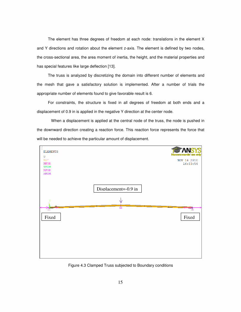
The element has three degrees of freedom at each node: translations in the element X
and Y directions and rotation about the element z-axis. The element is defined by two nodes,
the cross-sectional area, the area moment of inertia, the height, and the material properties and
has special features like large deflection [13].
The truss is analyzed by discretizing the domain into different number of elements and
the mesh that gave a satisfactory solution is implemented. After a number of trials the
appropriate number of elements found to give favorable result is 6.
For constraints, the structure is fixed in all degrees of freedom at both ends and a
displacement of 0.9 in is applied in the negative Y direction at the center node.
When a displacement is applied at the central node of the truss, the node is pushed in
the downward direction creating a reaction force. This reaction force represents the force that
will be needed to achieve the particular amount of displacement.
Figure 4.3 Clamped Truss subjected to Boundary conditions
Displacement=-0.9 in
Fixed Fixed
Page 25
16
- Hinged
For the truss with hinged boundary conditions, element type used for the mesh is LINK1.
Figure 4.4 LINK1 element
The element is defined by two nodes, the cross-sectional area, an initial strain, and the
material properties with features like plasticity, large deflection, birth and death etc. As in a pin-
jointed structure, no bending of the element is considered [13].
In this case, the truss is hinged at both ends i.e. displacements in X and Y directions are
fixed and a displacement of 0.9 in the negative Y direction is applied at the central node.
Figure 4.5 Truss subjected to hinged boundary conditions
Hinge Hinge
Displacement=0.
Page 26
17
4.2.1.2 Results
The equilibrium plots of the above analyzed structures are plotted in figure 4.7 and 4.10.
The nonlinear instability region is the region in which “snap-through” occurs and in which the
equilibrium path goes from one stable point (a) to another new stable point (b). The nonlinear
behavior places the critical limit load at point (a) equal to that at point (b), but the load limit
corresponds to a new structural shape. In case of bifurcation buckling at bifurcation point the
structure immediately becomes unstable and buckles. The member is unable to support any
additional load, which is not the case for nonlinear snap-through buckling.
The above cases are analyzed in ANSYS APDL. After subsequent trials a mesh of 6
elements is used.
a) Clamped Shallow Truss
For the clamped shallow truss, the resulting deformation is shown in figure 4.6.
Figure 4.6 Deformed clamped truss
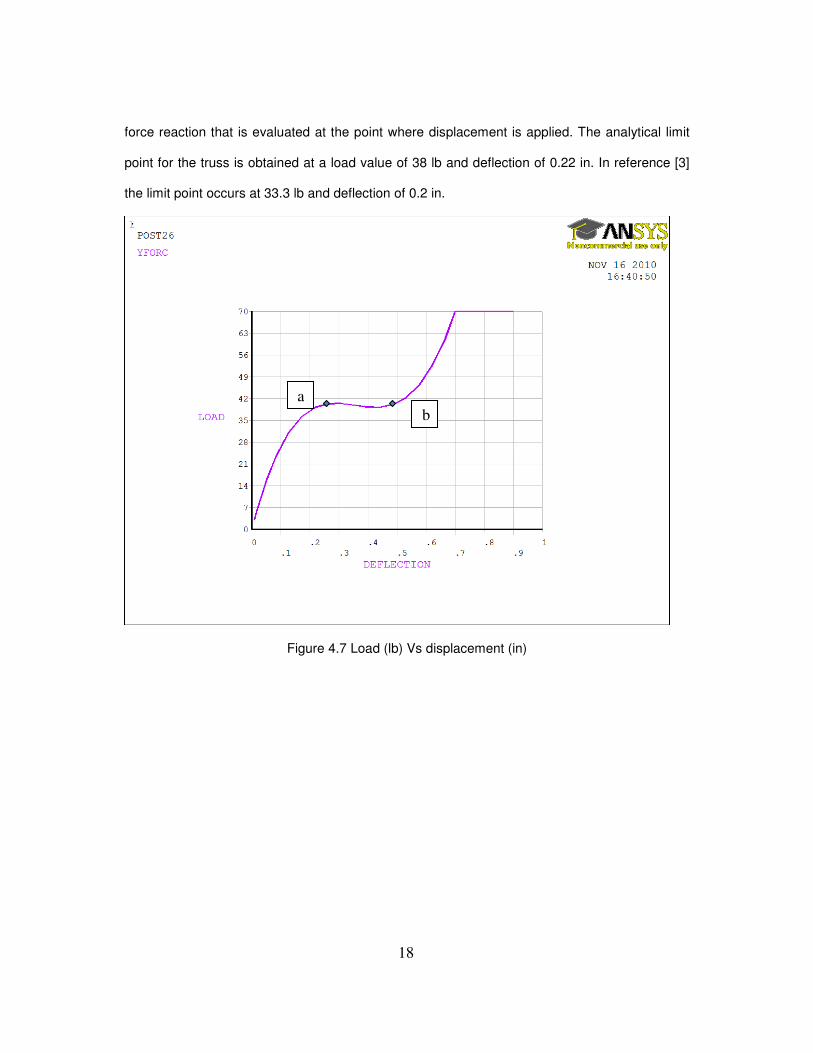
The graph of vertical load reaction at the central node against the displacement is
plotted in the figure 4.7. The results match with the results in [3]. Vertical load reaction is the
Page 27
18
force reaction that is evaluated at the point where displacement is applied. The analytical limit
point for the truss is obtained at a load value of 38 lb and deflection of 0.22 in. In reference [3]
the limit point occurs at 33.3 lb and deflection of 0.2 in.
Figure 4.7 Load (lb) Vs displacement (in)
a
b
Page 28
19
Figure 4.8 Load (lb) Vs Horizontal reaction
The maximum compressive force obtained in the members is 750 lb. In this case, as the central
node is gradually pushed downward, the vertical force reaction goes on increasing till it reaches
point (2) and so does the horizontal reaction force evaluated at the truss ends. The vertical load
values in (1-2-1) region of the graph in Figure (4.8) correspond to those in the post-buckling
region in Figure (4.7). The horizontal reaction goes on decreasing after it reaches point (2).
b) Hinged Shallow Truss
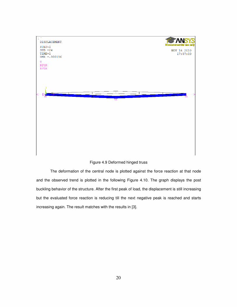
The shallow truss with hinged boundary conditions is deformed as depicted in the Figure (4.9)
1
2
Page 29
20
Figure 4.9 Deformed hinged truss
The deformation of the central node is plotted against the force reaction at that node
and the observed trend is plotted in the following Figure 4.10. The graph displays the post
buckling behavior of the structure. After the first peak of load, the displacement is still increasing
but the evaluated force reaction is reducing till the next negative peak is reached and starts
increasing again. The result matches with the results in [3].
Page 30
21
Figure 4.10 Load (lb) Vs deflection (in)
The limit point (a) for the truss occurs at 18 lb and 0.16 in.
The horizontal reaction force evaluated at the ends of the truss is plotted against the vertical
load reaction in Figure 4.11. The maximum compressive force obtained is 850 lb. After reaching
the maximum value at point (1) horizontal force decreases gradually. At point (1) the vertical
force becomes zero and then continues to be in the negative range till it again attains the value
of zero at point (2). The results match with the results in [3]. Reference [3] utilizes a 5 element
mesh for both cases to analyze the post buckling behavior of structures.
a b
Page 31
22
Figure 4.11 Load (lb) Vs Horizontal Reaction (lb)
4.2.2 Diagonal Truss
The diagonal truss is analyzed by assuming geometric and material non linearity.
4.2.2.1 ANSYS Simulation
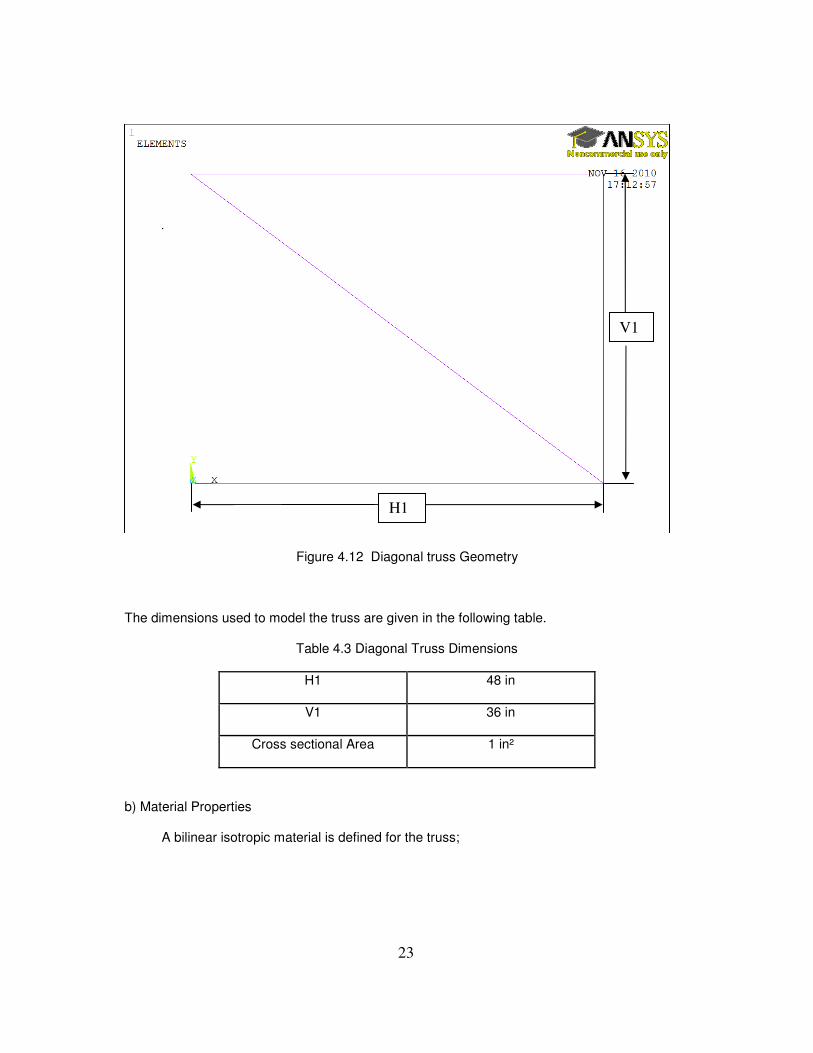
a) Geometry
The geometry of the Diagonal Truss is as shown below in figure 4.12;
1 2
Page 32
23
Figure 4.12 Diagonal truss Geometry
The dimensions used to model the truss are given in the following table.
Table 4.3 Diagonal Truss Dimensions
H1 48 in
V1 36 in
Cross sectional Area 1 in²
b) Material Properties
A bilinear isotropic material is defined for the truss;
H1
V1
Page 33
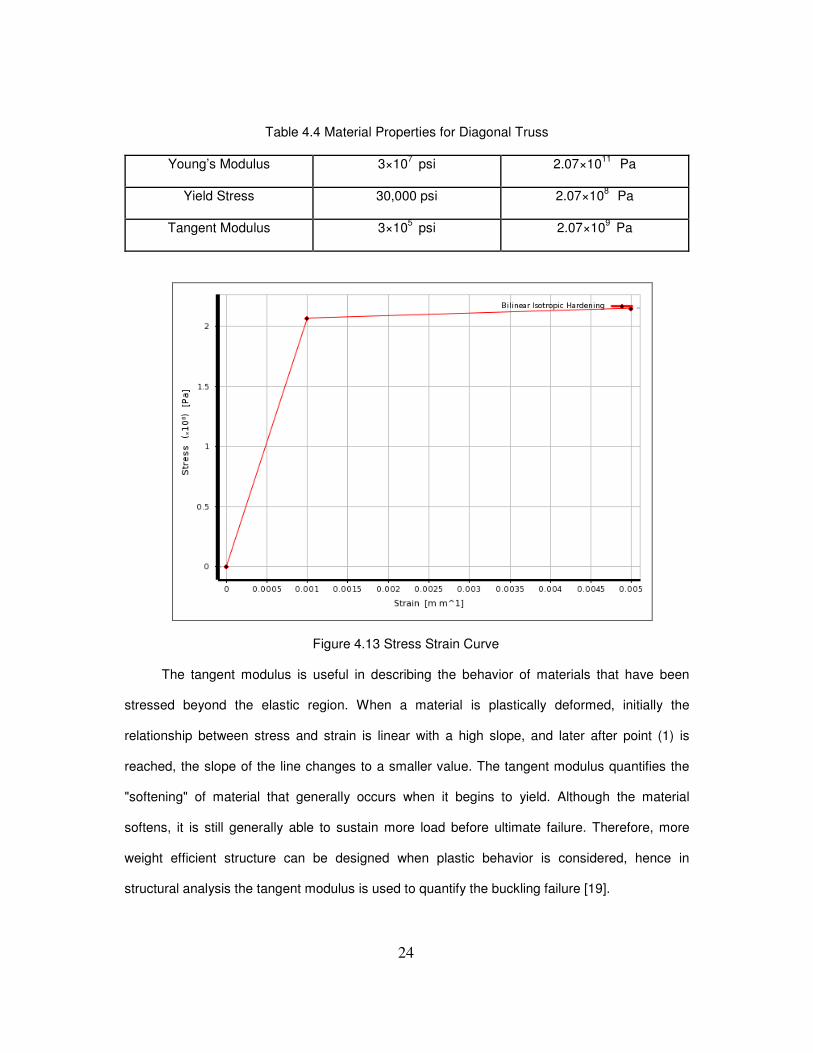
24
Table 4.4 Material Properties for Diagonal Truss
Young’s Modulus 3×10⁷ psi 2.07×10
11 Pa
Yield Stress 30,000 psi 2.07×10⁸
Pa
Tangent Modulus 3×10⁵ psi 2.07×10
9 Pa
Figure 4.13 Stress Strain Curve
The tangent modulus is useful in describing the behavior of materials that have been
stressed beyond the elastic region. When a material is plastically deformed, initially the
relationship between stress and strain is linear with a high slope, and later after point (1) is
reached, the slope of the line changes to a smaller value. The tangent modulus quantifies the
"softening" of material that generally occurs when it begins to yield. Although the material
softens, it is still generally able to sustain more load before ultimate failure. Therefore, more
weight efficient structure can be designed when plastic behavior is considered, hence in
structural analysis the tangent modulus is used to quantify the buckling failure [19].
Page 34
25
c) Boundary Conditions
A displacement of 3 in is applied on node 6 in the negative Y direction. Nodes 9 and 1 are fixed
as shown in figure 4.13.
Figure 4.14 Boundary conditions for Diagonal Truss
4.2.2.2 Results
Due to the applied boundary conditions the truss is deformed. The deformed shape of the truss
is as shown in the Figure 4.14.
Node 9
Node 1
Node
Page 35
26
Figure 4.15 Deformed Shape of Diagonal Truss
Following is the plot of load reaction Vs deflection in Figure 4.16. The limit point of the truss
occurs at a load of 1800 lb and a deflection value of 0.2 in. When the applied displacement
pushes the truss in the negative Y direction, buckling is experienced in members 1 and 2
leading to a plastic deformation of the truss. The results match with the reference [15], where a
non linear analysis program ADINA is used.
1
2
Page 36
27
Figure 4.16 Load (lb) Vs Deflection (in)
4.2.3 Shallow Arch
4.2.3.1 ANSYS Simulation
The shallow arch is modeled using BEAM3 elements.
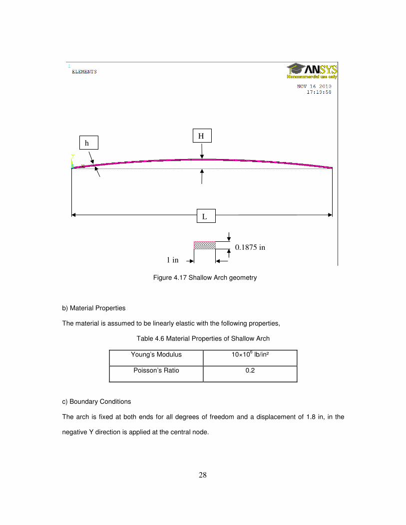
a) Geometry
The shallow arch is modeled using the following dimensions,
Table 4.5 Dimensions of Shallow Arch
Cross Section Area 0.188 in²
Area Moment of Inertia 0.00055 in4
H 1.09 in
H 0.1875 in
L 34 in
Page 37
28
Figure 4.17 Shallow Arch geometry
b) Material Properties
The material is assumed to be linearly elastic with the following properties,
Table 4.6 Material Properties of Shallow Arch
Young’s Modulus 10×106 lb/in²
Poisson’s Ratio 0.2
c) Boundary Conditions
The arch is fixed at both ends for all degrees of freedom and a displacement of 1.8 in, in the
negative Y direction is applied at the central node.
L
h H
1 in
0.1875 in
Page 38
29
Figure 4.18 Boundary Conditions for Shallow Arch
4.2.3.2 Results
Mesh convergence is obtained on discretizing the domain by employing 24 elements. The
applied boundary conditions cause the arch to deform at the center and towards the ends as
shown in the figure 4.19 and 4.20 attached below.
Fixed Fixed
Displacement=-1.8 in
Page 39
30
Figure 4.19 Deformed Shape of Shallow Arch with central displacement = -1.8 in
Figure 4.20 Deformed Shape of Shallow Arch with central displacement = -0.5 in
Page 40
31
The vertical load reaction at the central node is plotted against the deflection at the central
node,
Figure 4.21 Load (lb) Vs Displacement (in)
The limit point of the truss occurs at a load value of 35 lb and a deflection value of 0.4 in.
As the point of critical load is reached the structure goes into the non linear i.e. post buckling
region. The region continues till the load of 35 lb is reached at a corresponding displacement
value of 1.75 in.
The results match with those given in reference [15], where half of the arch is analyzed
using 12 equal length beam elements.
Page 41
32
CHAPTER 5
SHELL STRUCTURES
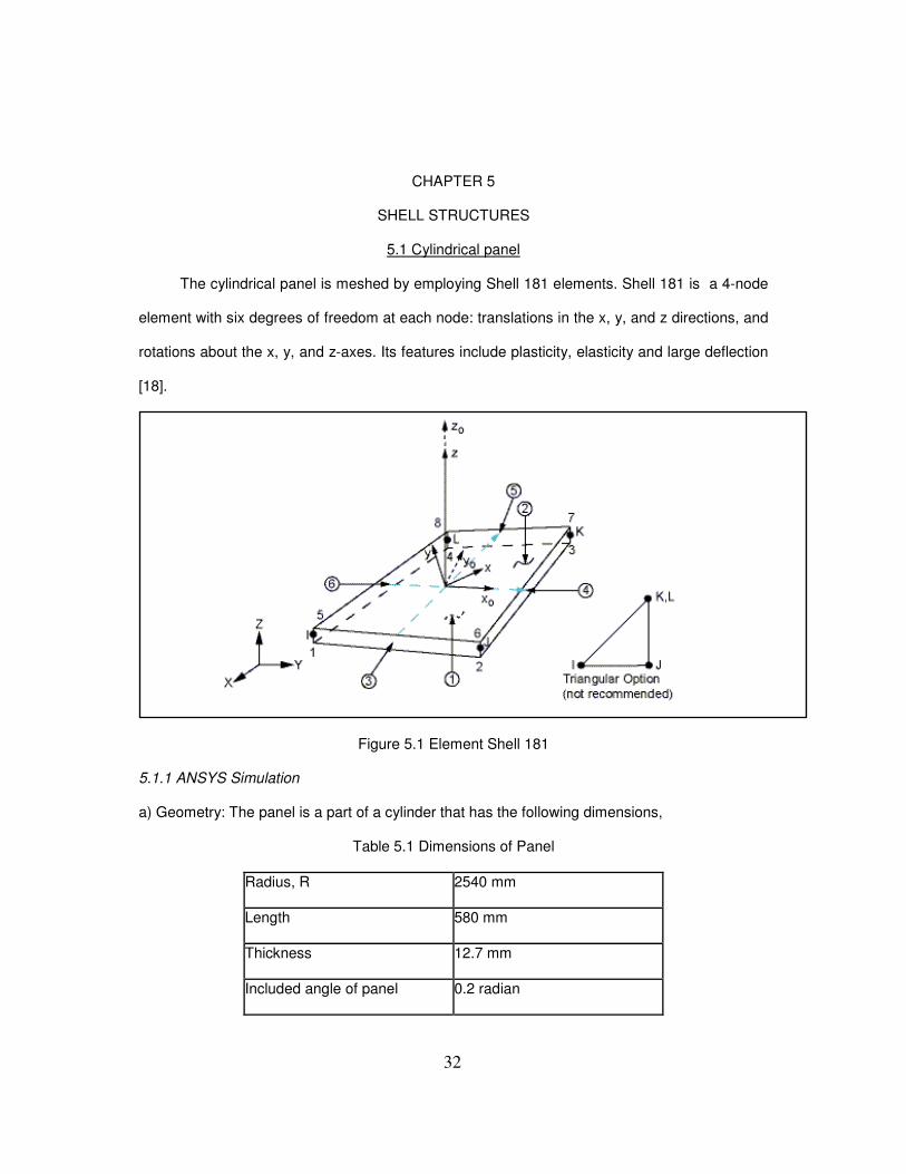
5.1 Cylindrical panel
The cylindrical panel is meshed by employing Shell 181 elements. Shell 181 is a 4-node
element with six degrees of freedom at each node: translations in the x, y, and z directions, and
rotations about the x, y, and z-axes. Its features include plasticity, elasticity and large deflection
[18].
Figure 5.1 Element Shell 181
5.1.1 ANSYS Simulation
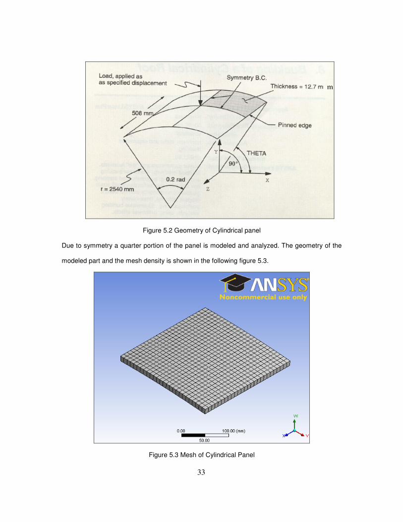
a) Geometry: The panel is a part of a cylinder that has the following dimensions,
Table 5.1 Dimensions of Panel
Radius, R 2540 mm
Length 580 mm
Thickness 12.7 mm
Included angle of panel 0.2 radian
Page 42
33
Figure 5.2 Geometry of Cylindrical panel
Due to symmetry a quarter portion of the panel is modeled and analyzed. The geometry of the
modeled part and the mesh density is shown in the following figure 5.3.
Figure 5.3 Mesh of Cylindrical Panel
m
Page 43
34
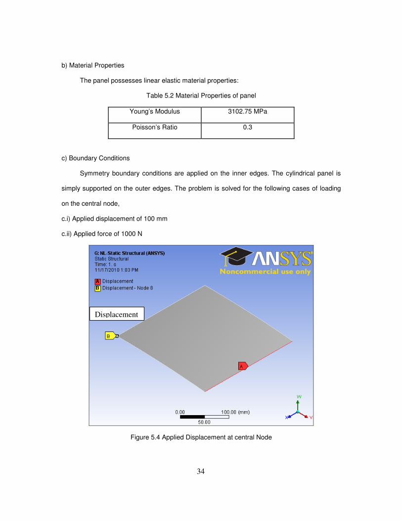
b) Material Properties
The panel possesses linear elastic material properties:
Table 5.2 Material Properties of panel
Young’s Modulus 3102.75 MPa
Poisson’s Ratio 0.3
c) Boundary Conditions
Symmetry boundary conditions are applied on the inner edges. The cylindrical panel is
simply supported on the outer edges. The problem is solved for the following cases of loading
on the central node,
c.i) Applied displacement of 100 mm
c.ii) Applied force of 1000 N
Figure 5.4 Applied Displacement at central Node
Displacement
Page 44
35
Figure 5.5 Applied Force at Central node
5.1.2 Results
With applied displacement at the central node, the panel deforms as in the below figure 5.5
Figure 5.6 Deformed Shape of Cylindrical Panel
Force
Page 45
36
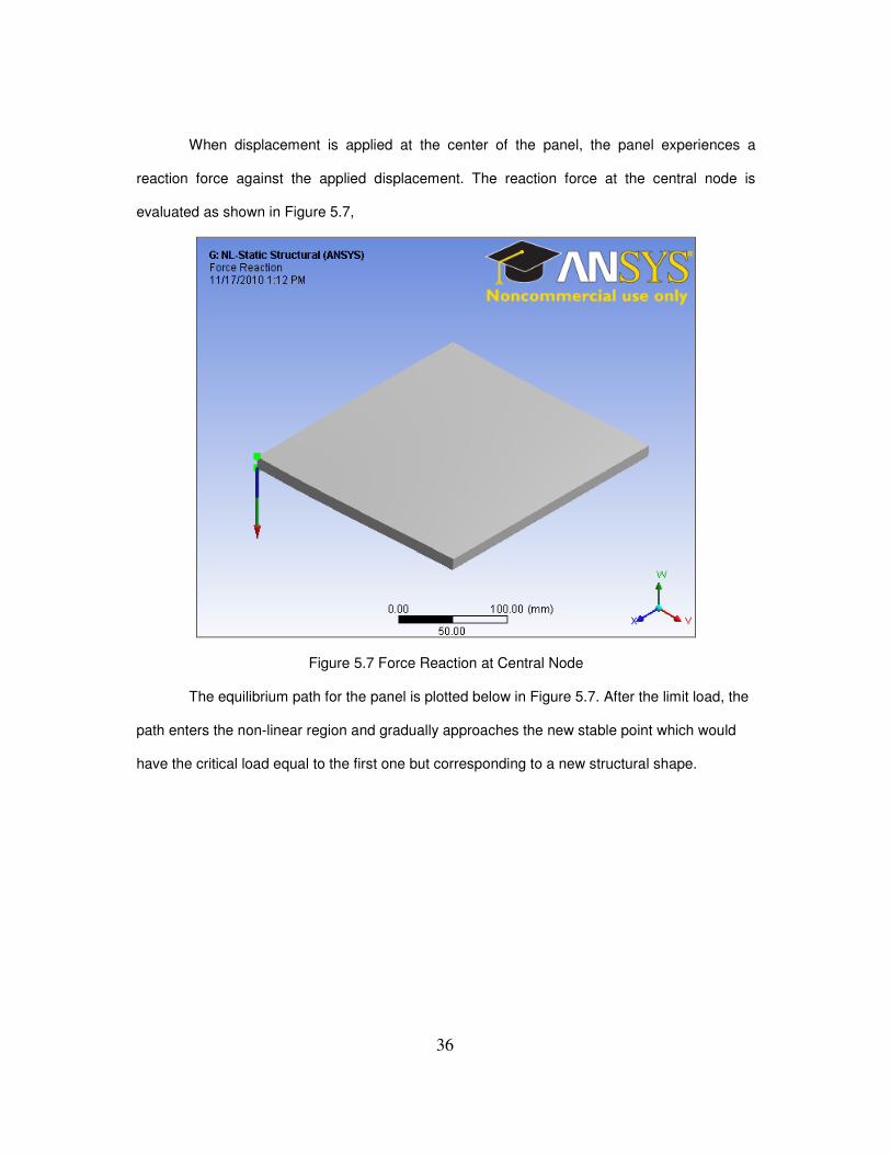
When displacement is applied at the center of the panel, the panel experiences a
reaction force against the applied displacement. The reaction force at the central node is
evaluated as shown in Figure 5.7,
Figure 5.7 Force Reaction at Central Node
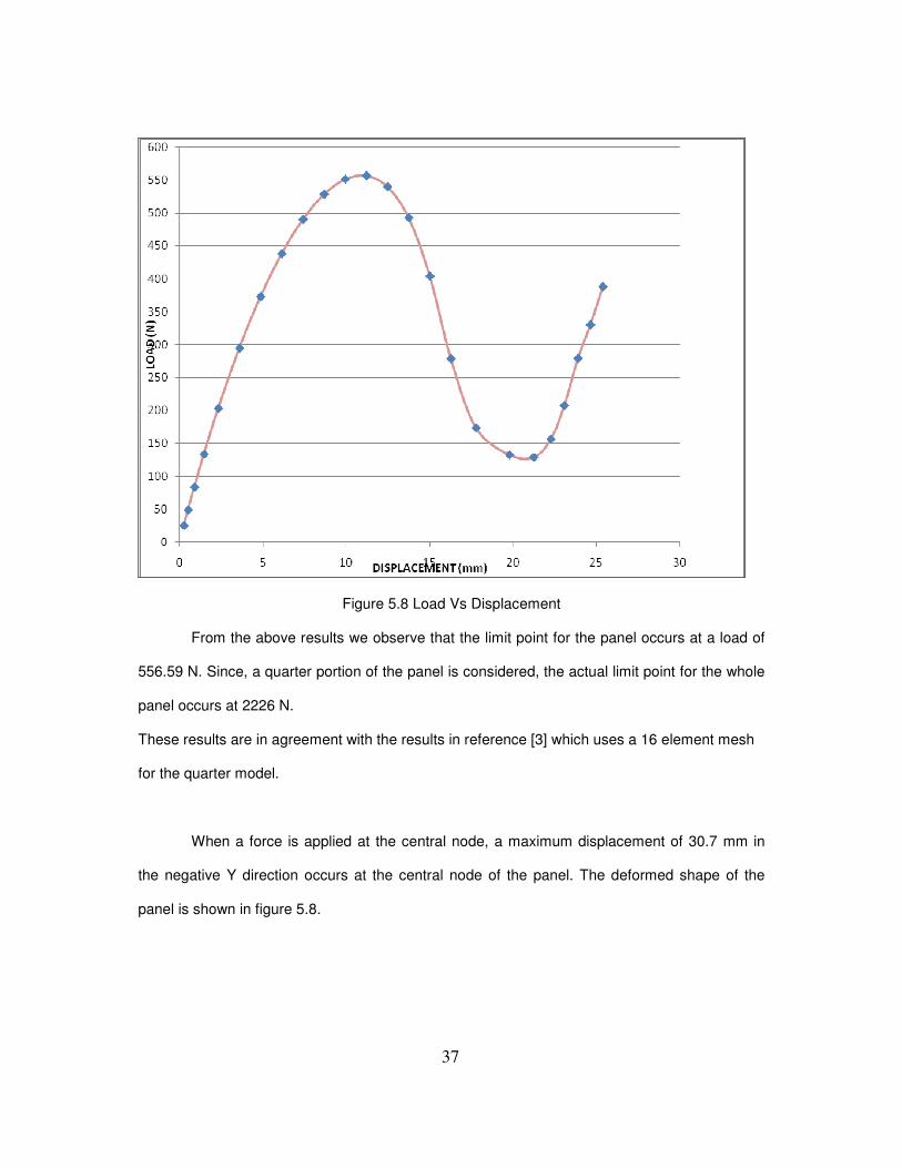
The equilibrium path for the panel is plotted below in Figure 5.7. After the limit load, the
path enters the non-linear region and gradually approaches the new stable point which would
have the critical load equal to the first one but corresponding to a new structural shape.
Page 46
37
Figure 5.8 Load Vs Displacement
From the above results we observe that the limit point for the panel occurs at a load of
556.59 N. Since, a quarter portion of the panel is considered, the actual limit point for the whole
panel occurs at 2226 N.
These results are in agreement with the results in reference [3] which uses a 16 element mesh
for the quarter model.
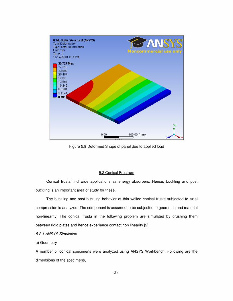
When a force is applied at the central node, a maximum displacement of 30.7 mm in
the negative Y direction occurs at the central node of the panel. The deformed shape of the
panel is shown in figure 5.8.
Page 47
38
Figure 5.9 Deformed Shape of panel due to applied load
5.2 Conical Frustrum
Conical frusta find wide applications as energy absorbers. Hence, buckling and post
buckling is an important area of study for these.
The buckling and post buckling behavior of thin walled conical frusta subjected to axial
compression is analyzed. The component is assumed to be subjected to geometric and material
non-linearity. The conical frusta in the following problem are simulated by crushing them
between rigid plates and hence experience contact non linearity [2].
5.2.1 ANSYS Simulation
a) Geometry
A number of conical specimens were analyzed using ANSYS Workbench. Following are the
dimensions of the specimens,
Page 48
39
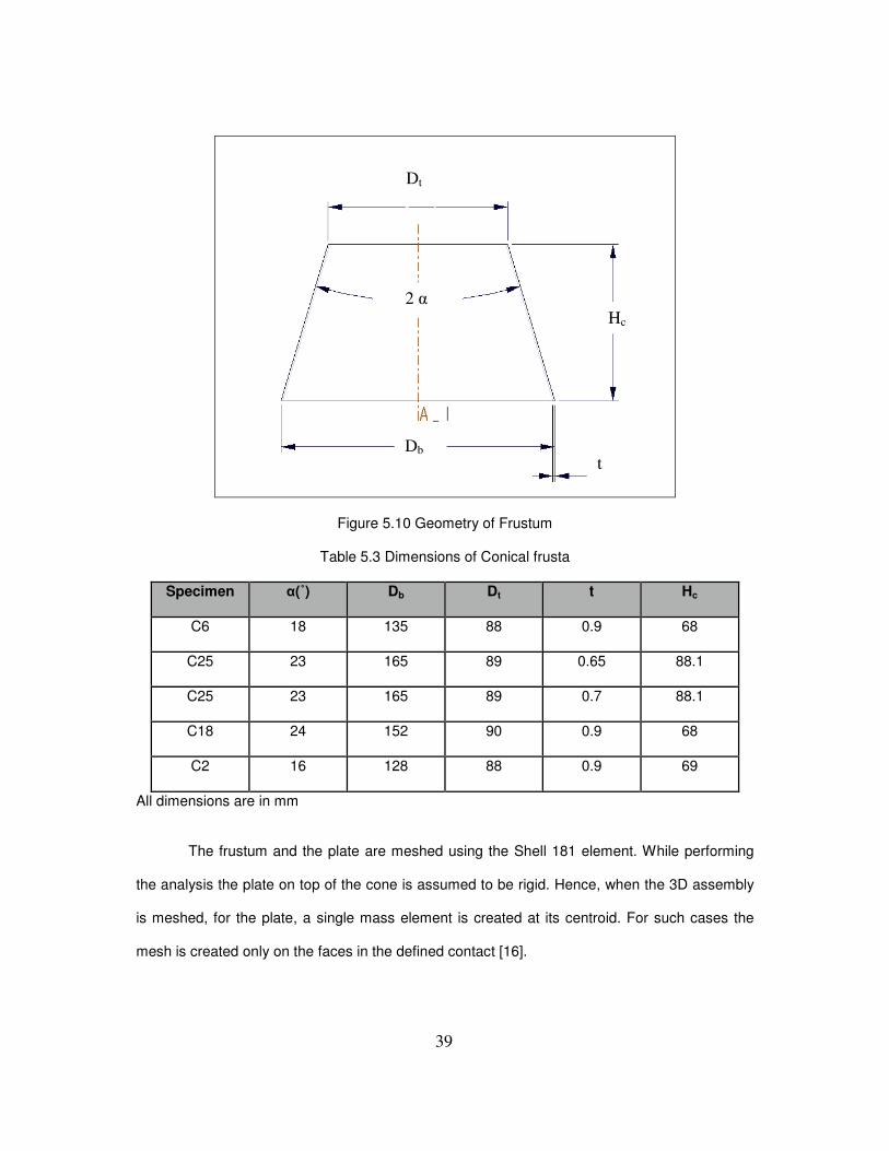
Figure 5.10 Geometry of Frustum
Table 5.3 Dimensions of Conical frusta
Specimen α(˚) Db Dt t Hc
C6 18 135 88 0.9 68
C25 23 165 89 0.65 88.1
C25 23 165 89 0.7 88.1
C18 24 152 90 0.9 68
C2 16 128 88 0.9 69
All dimensions are in mm
The frustum and the plate are meshed using the Shell 181 element. While performing
the analysis the plate on top of the cone is assumed to be rigid. Hence, when the 3D assembly
is meshed, for the plate, a single mass element is created at its centroid. For such cases the
mesh is created only on the faces in the defined contact [16].
Dt
Db
Hc
t
2 α
Page 49
40
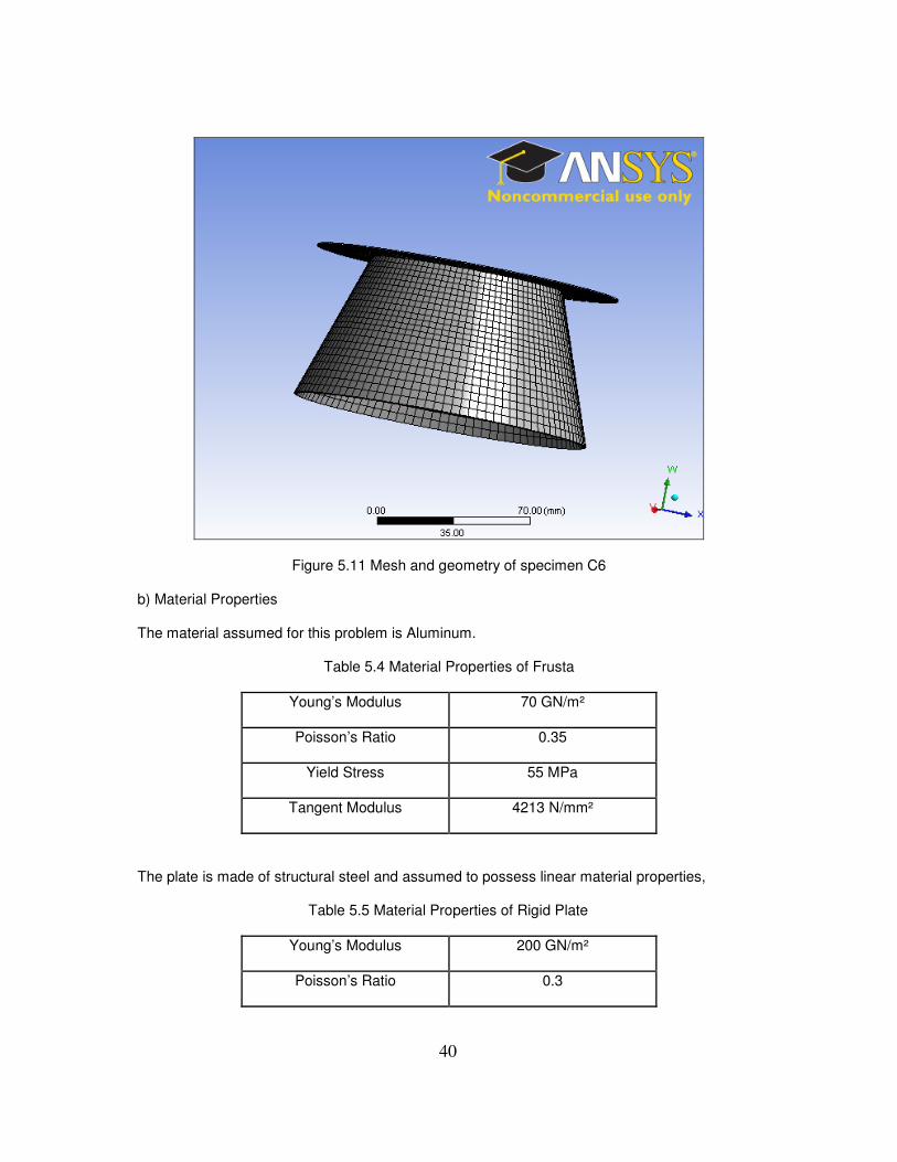
Figure 5.11 Mesh and geometry of specimen C6
b) Material Properties
The material assumed for this problem is Aluminum.
Table 5.4 Material Properties of Frusta
Young’s Modulus 70 GN/m²
Poisson’s Ratio 0.35
Yield Stress 55 MPa
Tangent Modulus 4213 N/mm²
The plate is made of structural steel and assumed to possess linear material properties,
Table 5.5 Material Properties of Rigid Plate
Young’s Modulus 200 GN/m²
Poisson’s Ratio 0.3
Page 50
41
c) Boundary Conditions
The cone is subjected to axial compression between rigid platens. Hence, while
modeling, the bottom edge of the cone is fixed and the top of the cone is subjected to
compression by the application of remote displacement of 15 mm on the rigid plate. With remote
displacement, workbench applies the specified displacement to the geometric center of the rigid
body.
Figure 5.12 Boundary conditions applied to specimen C6
5.2.2 Results
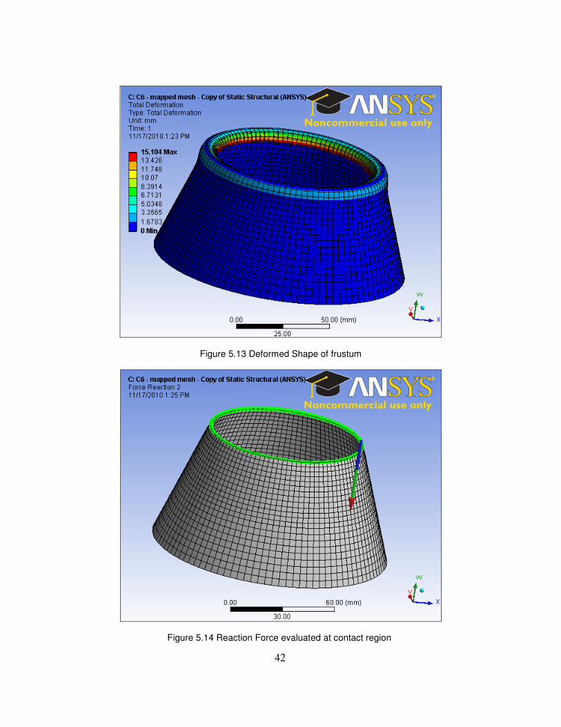
The applied displacement causes the conical frustum to deform. The deformed shape of the
frustum is shown in the figure 5.13.
Page 51
42
Figure 5.13 Deformed Shape of frustum
Figure 5.14 Reaction Force evaluated at contact region
Page 52
43
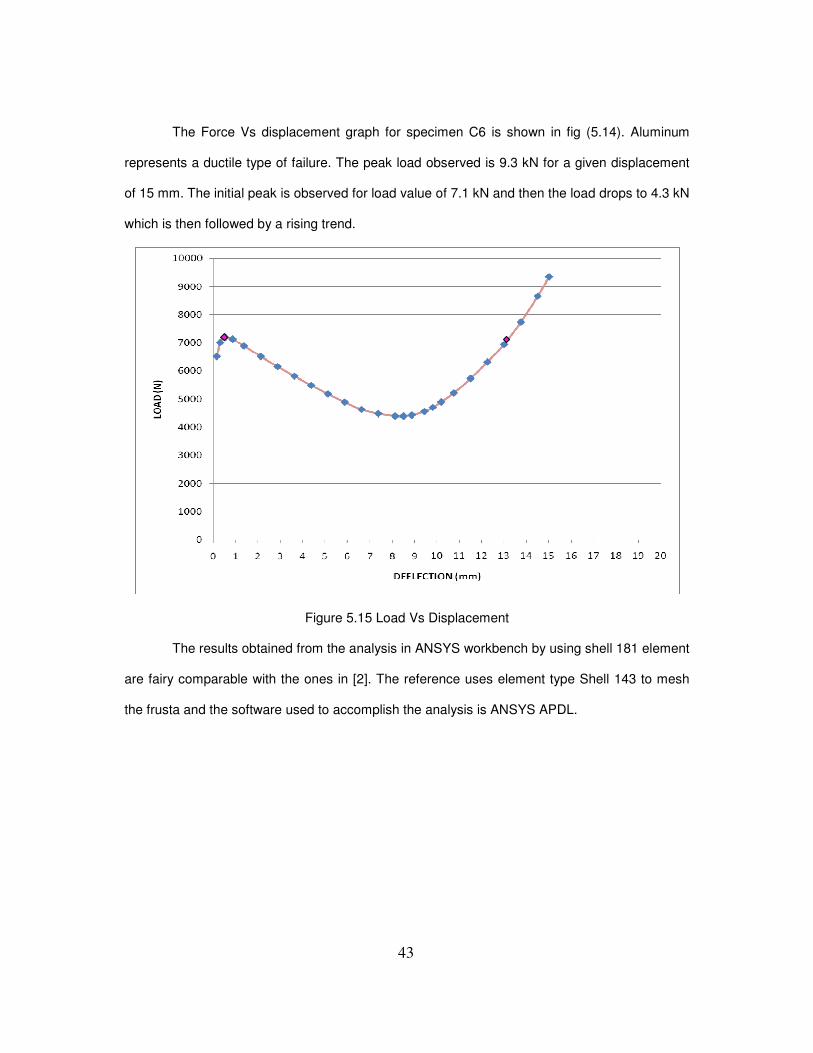
The Force Vs displacement graph for specimen C6 is shown in fig (5.14). Aluminum
represents a ductile type of failure. The peak load observed is 9.3 kN for a given displacement
of 15 mm. The initial peak is observed for load value of 7.1 kN and then the load drops to 4.3 kN
which is then followed by a rising trend.
Figure 5.15 Load Vs Displacement
The results obtained from the analysis in ANSYS workbench by using shell 181 element
are fairy comparable with the ones in [2]. The reference uses element type Shell 143 to mesh
the frusta and the software used to accomplish the analysis is ANSYS APDL.
Page 53
44
Table 5.6 Force Values for Frusta
ANSYS Workbench ANSYS APDL Experimental
Element Type Shell 181 Shell 143
Specimen Max Force
(kN)
Avg Force
(kN)
Max Force
(kN)
Avg Force
(kN)
Max Force
(kN)
C6 9.3 5.9 8.2 5.5 3.4
C25(0.65) 5.8 3.1 4.4 13.7 4.9
C25 (0.7) 6.3 3.5 4.4 13.7 4.9
C18 7.7 5.1 12.7 8.35 5.5
C2 14.7 7.7 9.2 7.2 4
The observed differences in the force values are the cumulative result of the difference
in Mesh density and the element type implemented. The Mesh used in this work has larger
mesh density. Also, under bending loads, for Shell 143, inferior results can be produced leading
to a need of a refined mesh [13] [18].
5.3 Eigen Value Buckling Load
The Eigen value buckling analysis is performed for all cases of structures and the Eigen
value buckling load is compared to the limit load obtained from the non-linear buckling
simulation. From the results in Table 5.7 it is observed that the eigen value buckling load is
higher in each case.
Eigen value buckling load is the load at which the structure experiences instability and
fails immediately.
Page 54
45
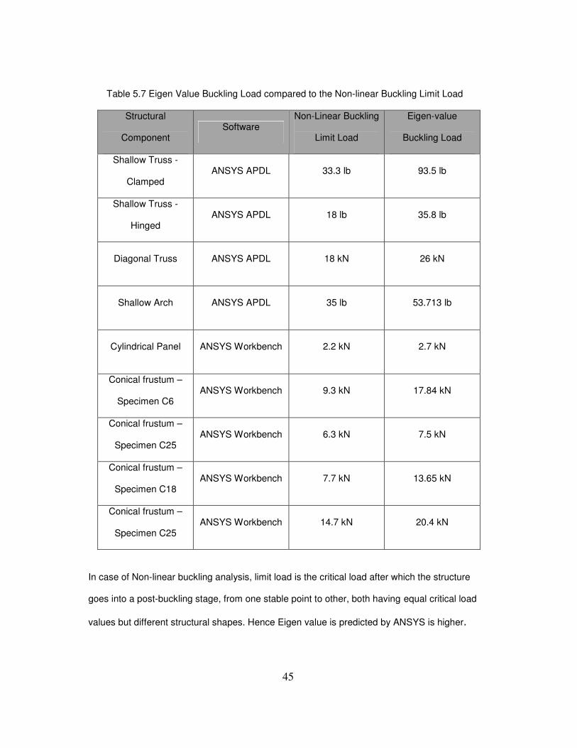
Table 5.7 Eigen Value Buckling Load compared to the Non-linear Buckling Limit Load
Structural
Component Software
Non-Linear Buckling
Limit Load
Eigen-value
Buckling Load
Shallow Truss -
Clamped ANSYS APDL 33.3 lb 93.5 lb
Shallow Truss -
Hinged ANSYS APDL 18 lb 35.8 lb
Diagonal Truss ANSYS APDL 18 kN 26 kN
Shallow Arch ANSYS APDL 35 lb 53.713 lb
Cylindrical Panel ANSYS Workbench 2.2 kN 2.7 kN
Conical frustum –
Specimen C6 ANSYS Workbench 9.3 kN 17.84 kN
Conical frustum –
Specimen C25 ANSYS Workbench 6.3 kN 7.5 kN
Conical frustum –
Specimen C18 ANSYS Workbench 7.7 kN 13.65 kN
Conical frustum –
Specimen C25 ANSYS Workbench 14.7 kN 20.4 kN
In case of Non-linear buckling analysis, limit load is the critical load after which the structure
goes into a post-buckling stage, from one stable point to other, both having equal critical load
values but different structural shapes. Hence Eigen value is predicted by ANSYS is higher.
Page 55
46
CHAPTER 6
CONCLUSION AND RECOMMENDATIONS
The main objective of the thesis is to investigate the buckling and post buckling
behavior of structural components that are bound to be subjected to heavy loads. Their complex
equilibrium paths are explained to inform engineers of possible nonlinear behavior in designs
and that instability may occur before a design bifurcation limit is reached. Understanding the
large elastic displacement of these types of structures can prevent sudden buckling failures
from applied operational and construction loads.
Structural components like the shallow truss, shallow arch, diagonal truss and shells
like conical frusta and cylindrical panel are chosen for examination. These are realistic
configurations that are directly usable in practical structural designs. These are simple metallic
structural components from which buckling and post buckling can be studied.
The investigated models displayed snap-through behavior after reaching a critical point.
The nonlinear behavior was identified by plotting the equilibrium paths of the center nodes. Post
buckling region is that area of these equilibrium plots, that lies between the two stable points
that correspond to the same critical load value but different displacement values.
This behavior of the analyzed structures signifies that under loaded condition the
structure does not become unstable and buckle immediately. These load values are compared
to the Eigen buckling load values and Eigen Value buckling load is found to be higher. At this
load the structure becomes unstable and buckles immediately.
The post buckling study can be extended to micro sized structures that are used in micro
electromechanical systems, for example, miniature trusses can be used as switches that can be
integrated into circuits. Also, sensitivity analysis of the post buckling behavior of these
structures can be accomplished. The Finite Element Methods software ANSYS APDL and
workbench can be successfully implemented for the same.
Page 56
47
APPENDIX A
DEFORMED SPECIMENS OF CONICAL FRUSTA
Page 57
48
Figure A.1 Example of Mesh density for frusta in reference [2]
Figure A.2 C25 Deformed Shape for thickness of 0.7 mm
Page 58
49
Figure A.3 C18 Deformed Shape
Figure A.4 C2 Deformed Shape
Page 59
50
APPENDIX B
EIGEN VALUE BUCKLING MODE SHAPES
Page 60
51
Figure B.1 Shallow Truss – Clamped
Figure B.2 Shallow Truss - Hinged
Page 61
52
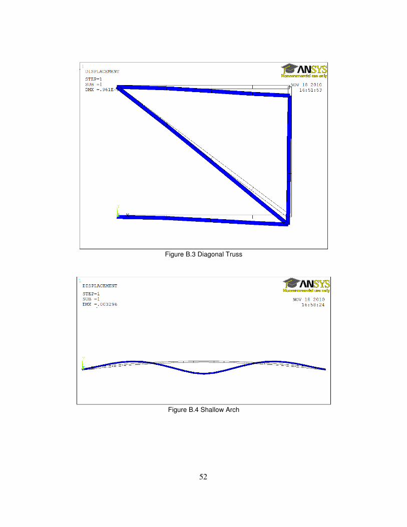
Figure B.3 Diagonal Truss
Figure B.4 Shallow Arch
Page 62
53
Figure B.5 Cylindrical Panel
Figure B.6 Conical Frustum Specimen C6
Page 63
54
REFERENCES
1] Buckling and post-buckling behavior of thin walled cylindrical steel shells with varying
thickness subjected to uniform external pressure; S Aghajari, K Abedi and H Showkati, Thin
Walled Structures, 44, (2006) 904-909
2] Buckling of thin conical frustum under axial loads; N. K. Gupta, N. Mohamed Sheriff, R.
Velmurugan, Thin Walled Structures, 44, (2006) 986-996
3] Post buckling behavior of plates and shells using a mindlin shallow shell formulation; A. Pica
and R. D. Wood, Computers and Structures, Vol. 12, pp 759-768
4] Buckling of Axially compressed conical shells of linearly variable thickness using structural
model; Chawalit Thinvongpituk and Pisit Techarungpaisarn, The 17th
annual conference of
Mechanical Engineering Network of Thiland, Oct 2003
5] The Inelastic post buckling analysis of space steel trusses using the generalized
displacement control method; Huu Tai Thai and Seung Eock Kim, 5th
International Symposium
on Steel Structures
6] Plastic buckling of conical shells under axial compression; H Ramsey, J. of Mechanical
Science, Vol 19, pp 257-270, 1977
7] Axisymmetric axial crushing of thin frusta; N. K. Gupta and H. Abbas, Thin Walled Structures,
36 (2000) 169-179
8] Elastic buckling and post buckling behavior of widely stiffened conical shells under axial
compression; A. Spagnoli, M. K. Chryssanthopoulos, Engineering Structures 21 (1999) 845-855
9] The application of Finite Element Methods to the Large Deflection Geometrically Non Linear
behavior of Cylindrical Shells, A.B. Sabir and A. C. Lock, Variational methods in Engineering, pp
66-75.
10] Buckling of thin walled conical shells under uniform external pressure, B S Golzan and H.
Showkati, Thin Walled Structures 46 (2008) 516-529
Page 64
55
11] Hill C.D., Blandford G.E. and Wang S.T. (1989) Post-buckling analysis of steel space
trusses, Journal of Structural Engineering, Vol. 115, No. 4, pp. 900-919.
12] Non-Linear Buckling and post buckling analysis of shells of revolution; Tao Hong, Thesis,
Sep 1999
13] www.kxcad.net
14] Sensitivity Analysis of the Post Buckling Behavior of Elastic Structures; H. A. Mang, G
Hofinger and X. Jia
15] Solutions for Structural problems solved using ADINA.
16] Finite Element Simulations with ANSYS Workbench 12
17] ANSYS tutotial: University of Alberta
18] ANSYS Help Manual
19] The Finite Element Method and Applications in Engineering using ANSYS, Madenci,
Erdogan.
Page 65
56
BIOGRAPHICAL INFORMATION
Shruti Deshpande has completed her Bachelor’s degree in Production Engineering from Pune
university in 2005. She worked with BOSCH for two years after earning the degree. She started
her Master’s in Mechanical Engineering in the Spring of 2009 and completed her degree in Fall
2010. During her tenure as a Master’s student, she served as a Graduate teaching Assistant for
Dr. Kent Lawrence. Her thesis is based on the study of buckling and post buckling of Structural
Components, incorporating the use of Finite Element Analysis tools such as ANSYS APDL and
ANSYS Workbench. Her work interests are Finite Element Methods and Analysis and Computer
Aided Design.