Buckling Delamination with Application to Films and Laminates Thermal gradient with interruption of heat transfer across crack. Mixed mode interface crack Buckling delamination Compression in film producing buckling No crack driving force due to film stress; Unless Show Volinsky movie
Transcript
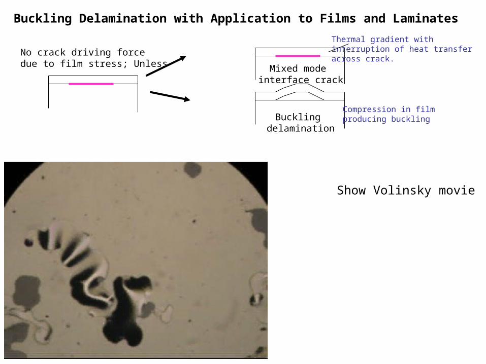
Buckling Delamination with Application to Films and Laminates
Thermal gradient withinterruption of heat transferacross crack.
Mixed mode interface crack
Buckling delamination
Compression in filmproducing buckling
No crack driving forcedue to film stress; Unless
Show Volinsky movie
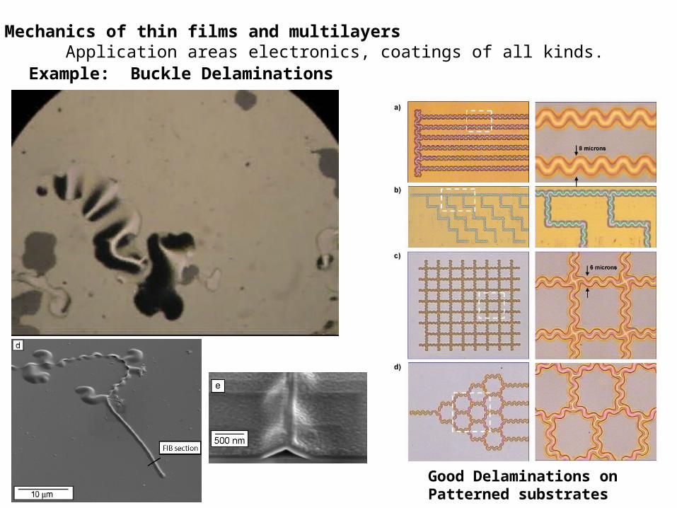
Mechanics of thin films and multilayers Application areas electronics, coatings of all kinds.
Example: Buckle Delaminations
Good Delaminations on Patterned substrates
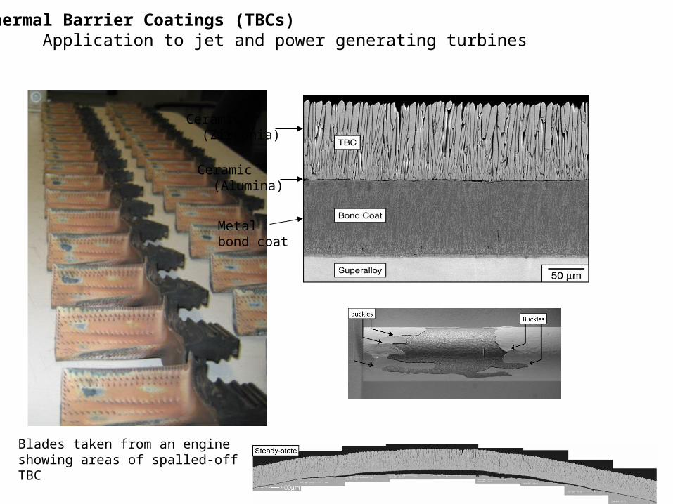
Thermal Barrier Coatings (TBCs) Application to jet and power generating turbines
Blades taken from an engineshowing areas of spalled-offTBC
Ceramic (Zirconia)
Ceramic (Alumina)
Metal bond coat
Straight-sided
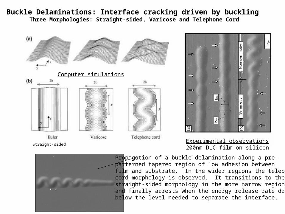
Buckle Delaminations: Interface cracking driven by buckling Three Morphologies: Straight-sided, Varicose and Telephone Cord
Propagation of a buckle delamination along a pre-patterned tapered region of low adhesion betweenfilm and substrate. In the wider regions the telephonecord morphology is observed. It transitions to thestraight-sided morphology in the more narrow regionand finally arrests when the energy release rate dropsbelow the level needed to separate the interface.
Computer simulations
Experimental observations200nm DLC film on silicon
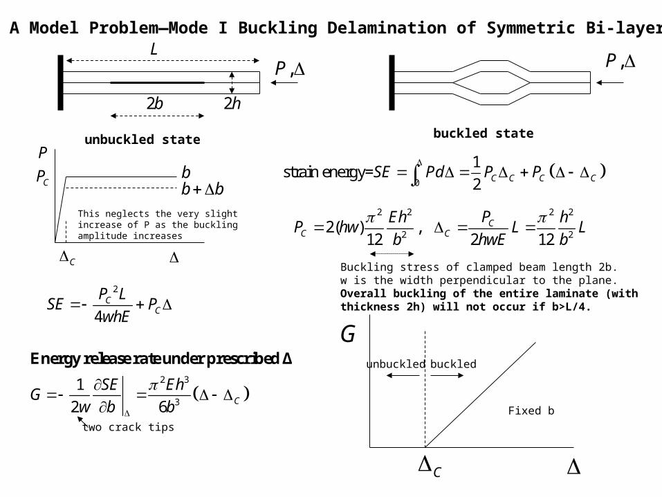
A Model Problem—Mode I Buckling Delamination of Symmetric Bi-layer
,P
2b
L
CP
P
C
0
1strain energy=
2 C C C CSE Pd P P
unbuckled state buckled state
2 2 2 2
2 22( ) ,
12 2 12C
C C
PEh hP hw L L
b hwE b
2h
Buckling stress of clamped beam length 2b.w is the width perpendicular to the plane.Overall buckling of the entire laminate (with thickness 2h) will not occur if b>L/4.
2
4C
C
P LSE P
whE
2 3
3
1
2 6 C
SE EhG
w b b
Energy release rate under prescribed Δ
two crack tips
G
C
This neglects the very slightincrease of P as the bucklingamplitude increases
unbuckled buckled
Fixed b
,P
bb b
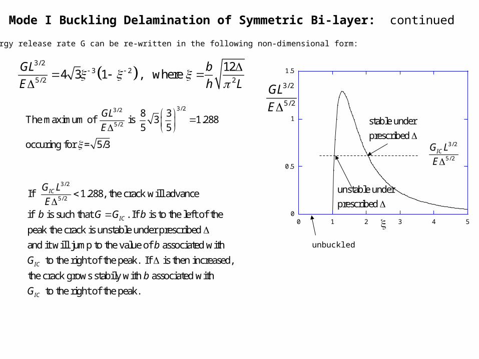
Mode I Buckling Delamination of Symmetric Bi-layer: continued
The energy release rate G can be re-written in the following non-dimensional form:
3/ 2
3 25/ 2 2
124 3 1 , where
GL b
E h L
0
0.5
1
1.5
0 1 2 3 4 5
3/ 2
5/ 2
GL
E3/ 23/ 2
5/ 2
8 3The maximum of is 3 1.288
5 5
occuring for = 5/3
GL
E
unbuckled
stable under
prescribed
unstable under
prescribed
3/ 2
5/ 2ICG L
E
3/ 2
5/ 2If 1.288, the crack will advance
if is such that . If is to the left of the
peak the crack is unstable under prescribed
and it will jump to the value of associated with
to the
IC
IC
IC
G L
Eb G G b
b
G
right of the peak. If is then increased,
the crack grows stabily with associated with
to the right of the peak.IC
b
G
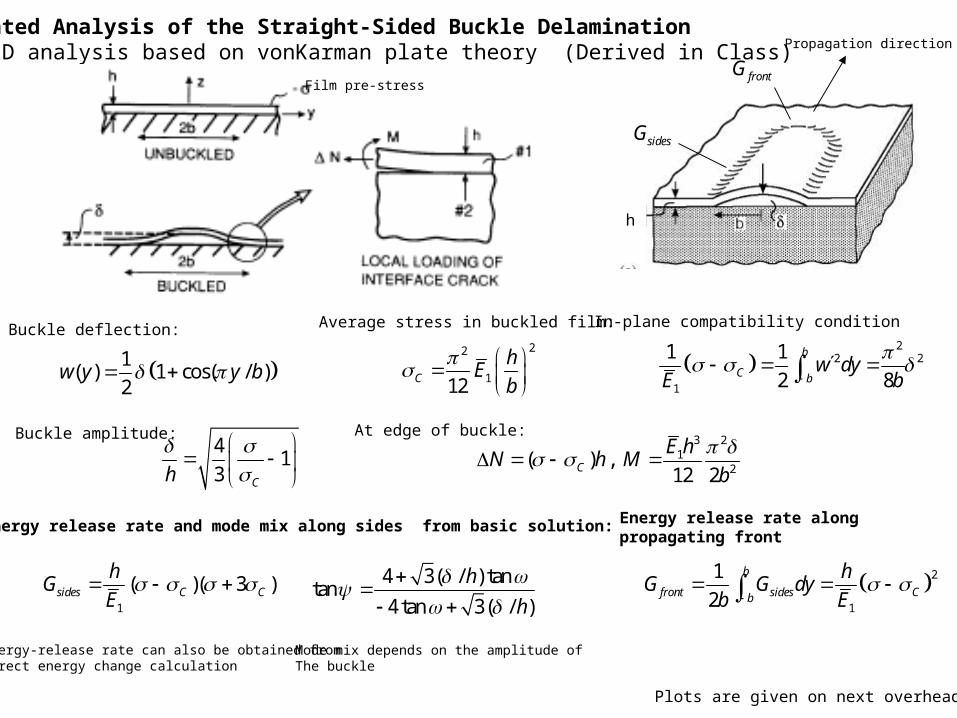
Abbreviated Analysis of the Straight-Sided Buckle Delamination A 1D analysis based on vonKarman plate theory (Derived in Class) Propagation direction
h
Film pre-stress
Buckle deflection:
1( ) 1 cos( / )
2w y y b
Average stress in buckled film:
22
112C
hE
b
In-plane compatibility condition
2
2 2
1
1 1
2 8
b
C bw dy
E b
At edge of buckle:3 2
12
( ) ,12 2C
E hN h M
b
Energy release rate and mode mix along sides from basic solution:
1
( )( 3 )sides C C
hG
E
Buckle amplitude:4
13 Ch
4 3( / ) tantan
4 tan 3( / )
h
h
Energy-release rate can also be obtained fromdirect energy change calculation
Mode mix depends on the amplitude ofThe buckle
Energy release rate alongpropagating front
2
1
1
2
b
front sides Cb
hG G dy
b E
sidesG
frontG
Plots are given on next overhead
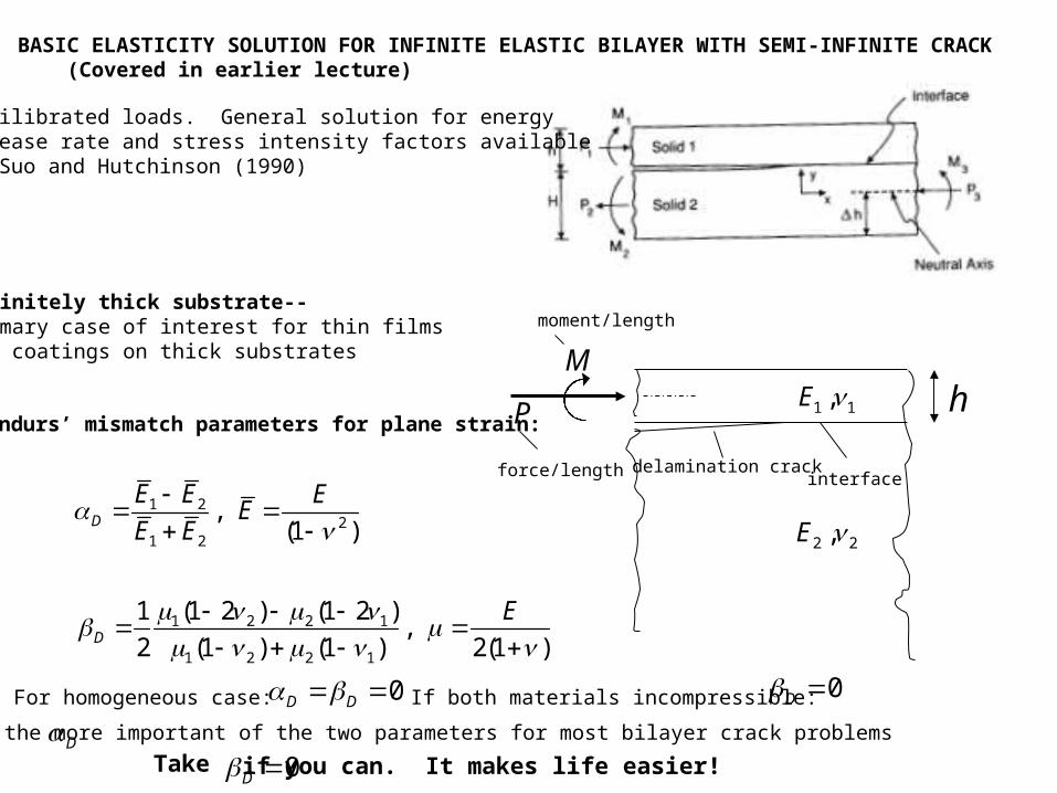
BASIC ELASTICITY SOLUTION FOR INFINITE ELASTIC BILAYER WITH SEMI-INFINITE CRACK (Covered in earlier lecture)
Equilibrated loads. General solution for energyrelease rate and stress intensity factors availablein Suo and Hutchinson (1990)
1 1,E
2 2,E
hP
M
moment/length
force/length interfacedelamination crack
Infinitely thick substrate--Primary case of interest for thin filmsand coatings on thick substrates
Dundurs’ mismatch parameters for plane strain:
1 22
1 2
,(1 )D
E E EE
E E
1 2 2 1
1 2 2 1
(1 2 ) (1 2 )1,
2 (1 ) (1 ) 2(1 )D
E
For homogeneous case: 0D D If both materials incompressible: 0D is the more important of the two parameters for most bilayer crack problems D
Take 0D if you can. It makes life easier!
1 1,E
2 2,E
hP
M
interfacedelamination crack
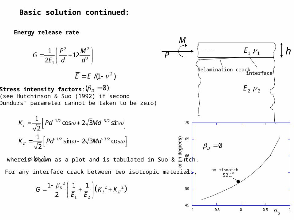
Basic solution continued:
Energy release rate
2 2
31
112
2
P MG
E d d
Stress intensity factors:(see Hutchinson & Suo (1992) if secondDundurs’ parameter cannot be taken to be zero)
( 0)D
1/ 2 3/ 2
1/ 2 3/ 2
1cos 2 3 sin
21
sin 2 3 cos2
I
II
K Pd Md
K Pd Md
where ( )D is shown as a plot and is tabulated in Suo & Hutch.
Note: For any interface crack between two isotropic materials,
2
2 2
1 2
1 1 1
2D
I IIG K KE E
2/(1 )E E
45
50
55
60
65
70
-1 -0.5 0 0.5 1D
52.1o
0D
no mismatch
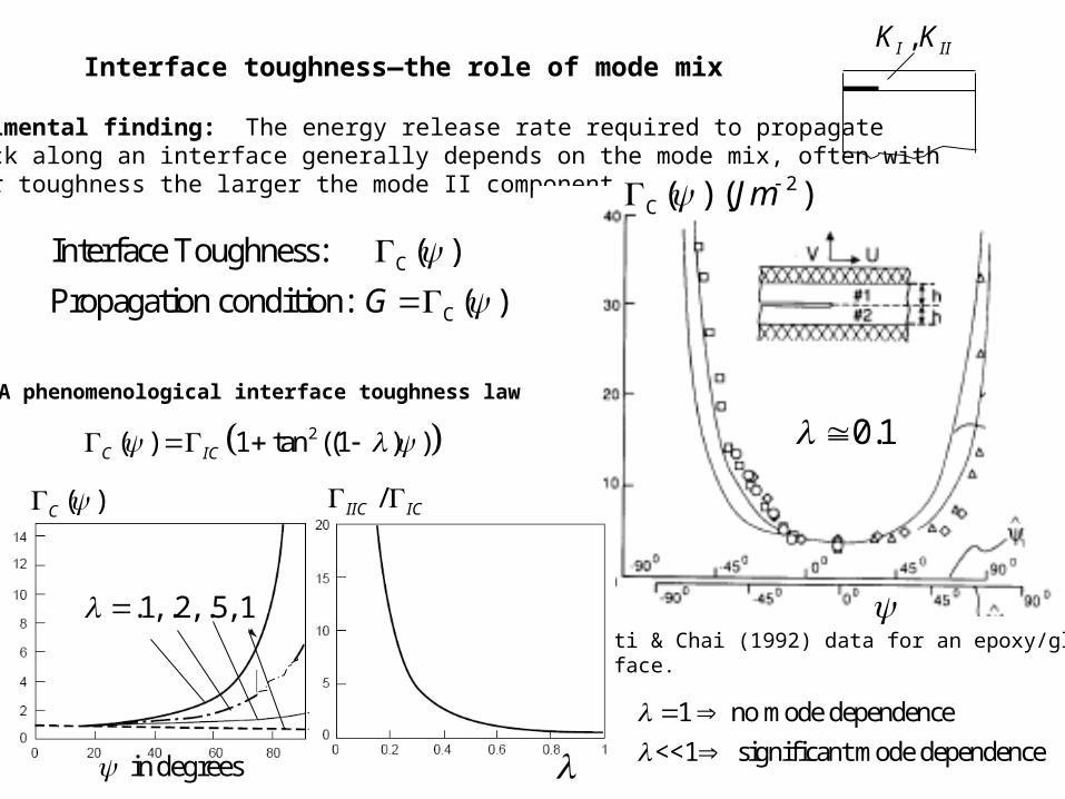
Interface toughness—the role of mode mix,I IIK K
Experimental finding: The energy release rate required to propagatea crack along an interface generally depends on the mode mix, often withlarger toughness the larger the mode II component.
C
C
Interface Toughness: ( )
Propagation condition: ( )G
2C ( ) ( )Jm
Liechti & Chai (1992) data for an epoxy/glassinterface.
A phenomenological interface toughness law
2( ) 1 tan ((1 ) )C IC
( )C
in degrees
.1, .2, .5, 1
/IIC IC
1 no mode dependence
<<1 significant mode dependence
0.1
0
0.5
1
1.5
2 4 6 8 10
C=(b/b
C)2
sides
curved front
-80
-60
-40
-20
0
2 4 6 8 10
C=(b/b
C)2
D=-1/2, 0, 1/2
mode mix along the delamination sides
0
2
4
6
8
10
2 4 6 8 10
C=(b/b
C)2
=0.2,0.4, 0.6, 0.8, 1
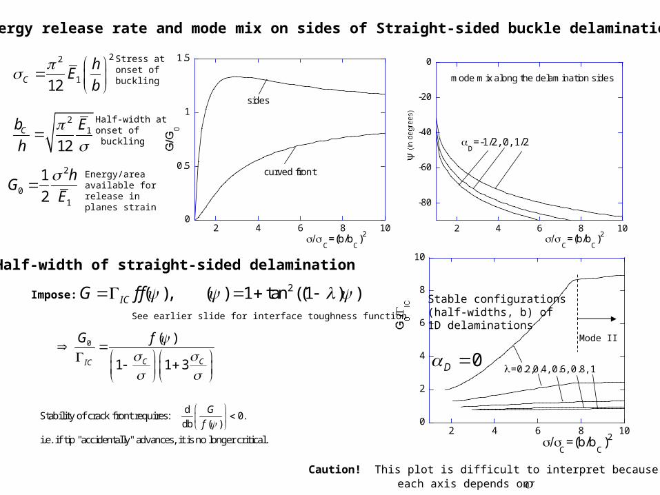
Energy release rate and mode mix on sides of Straight-sided buckle delamination
22
112C
hE
b
21
12Cb E
h
2
01
1
2
hG
E
Stress atonset of buckling
Half-width atonset of buckling
Energy/areaavailable forrelease inplanes strain
Half-width of straight-sided delamination
Impose:2( ), ( ) 1 tan ((1 ) )ICG f f
0 ( )
1 1 3C CIC
G f
dStability of crack front requires: 0.
db ( )
i.e. if tip "accidentally" advances, it is no longer critical.
G
f
See earlier slide for interface toughness function
Stable configurations(half-widths, b) of1D delaminations
0D Mode II
Caution! This plot is difficult to interpret becauseeach axis depends on
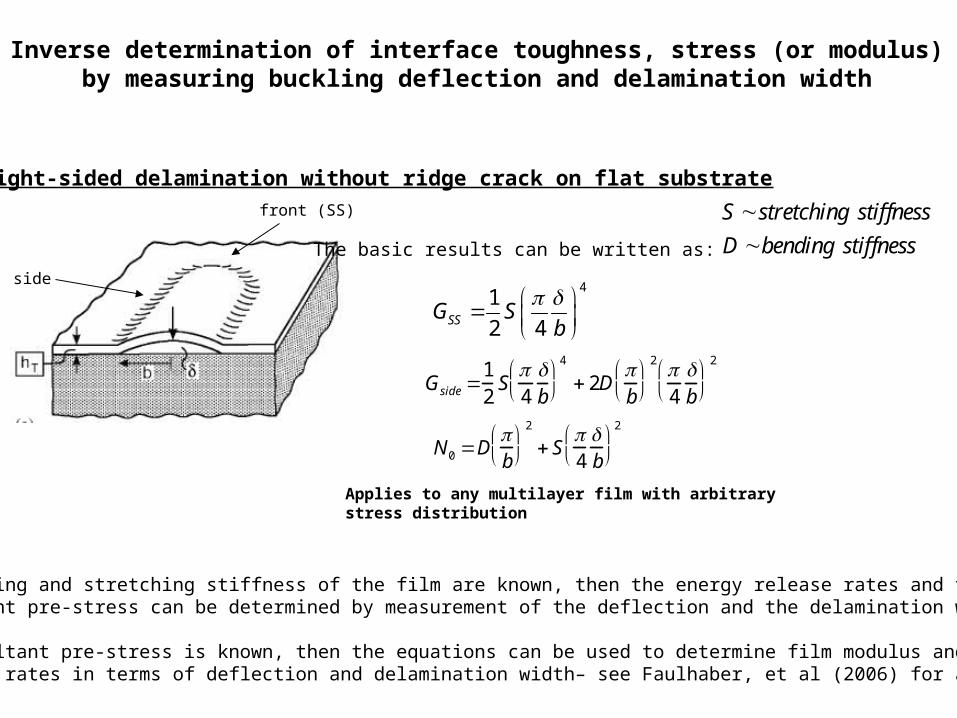
Inverse determination of interface toughness, stress (or modulus)by measuring buckling deflection and delamination width
Gside 12S4b
4
2Db
2 4b
2
41
2 4SSG Sb
N0 Db
2
S4b
2
Straight-sided delamination without ridge crack on flat substrate
front (SS)
side
S stretching stiffness
D bending stiffness
Applies to any multilayer film with arbitrarystress distribution
The basic results can be written as:
If bending and stretching stiffness of the film are known, then the energy release rates and theresultant pre-stress can be determined by measurement of the deflection and the delamination width.
If resultant pre-stress is known, then the equations can be used to determine film modulus andrelease rates in terms of deflection and delamination width– see Faulhaber, et al (2006) for an example.