Building a Dynamically Reconfigurable System Through a High Development Flow David de la Fuente, Jes´ us Barba, Xerach Pe˜ na and Juan Carlos L´ opez University of Castilla la Mancha Email: [email protected]Pablo Pe˜ nil and Pablo Pedro S´ anchez University of Cantabria Email: [email protected]Abstract—Partial Reconfiguration is one of the most attractive features of FPGAs. This feature provides new computing possibil- ities, such as the reduction of the total area required in a FPGA by means of functioning overlapping, or the modification of the design after its deployment, where a complete configuration is not needed. However, the design of partially reconfigurable systems is still a complex task. This work focuses on facilitating the design process and proposes a new development framework for dynamically configurable systems from high level UML/MARTE models which, starting from dynamically reconfigurable systems high level UML/MARTE models. Simulation and VHDL code are generated from those models, according to the specification requirements of the reconfigurable hardware captured in the specifications. To demonstrate this approach, a edge detection-based use case has been implemented with the developed framework. Keywords—UML/MARTE, SystemC, VHDL, reconfigurability, automatic code generation I. I NTRODUCTION For nearly two decades, advances on reconfigurable devices have made FPGAs more and more attractive for embedded system design. Besides the improvement shown in design area, performance, efficiency, and dedicated resources (i.e. DSPs or BRAMs), most important FPGAs vendors have also included a special characteristic in some of their products: the partial reconfiguration facility. This feature increases FPGA flexibility because its use is not limited to systems which are resolved at compilation time. A user can modify part of the device configuration at run time, allowing the modification of the initial design after its deployment without a complete configuration process. However, partial reconfiguration is far from being mainstream mainly because of the complexity of the development process [1]. One of the advantages of partial reconfiguration is the re- duction of the cost of a system due to area reuse. One example of this strategy is software defined radio applications where it is not necessary to deploy all possible radio waveforms at the same time. Another advantage is the flexibility provided by the fact that new components can be developed and instantiated after the initial deployment of the design [2]. However, there are some disadvantages when considering partial dynamic reconfiguration. Only a few device families implementing run-time reconfiguration are available and, once a manufacturer is chosen, the designer must remain tied to the tools and the workflows imposed by the vendor. Partial reconfiguration forces developers to deal with traditional co- design techniques and high-level design problems [3]. In addition, vendor design flows, such as ISE or Vivado design tools from Xilinx, work at a very low-level of abstraction [4]. The work described in this paper reduces the complexity of building partially reconfigurable systems by means of a design flow developed to ease the design of this type of systems. During the design flow, multiple design alternatives can be considered and evaluated in relation to the number and type of functional components deployed in the FPGA fabric. The objective is to analyze the possible implications of each one of these variations in the entire system behaviour. Therefore, different properties such as power consumption, performance, critical path, etc., should be considered. In order to obtain the best design configuration, new design approaches performing early design space exploration (DSE) processes have been developed. This enables the search for the best FPGA element configuration according to the specific characteristics that determine the correctness of the system behaviour. The development of electronic system-level (ESL) design methodologies [5] provides a strategy for designing complex systems, in which the initial key activity is specification. SystemC [6] is the most widely adopted language by the ESL community so as to write executable models of a system. Model-Driven Architecture (MDA) [7] is a design approach that enables expressing systems by means of models at differ- ent abstraction levels. As to MDA, the most widely accepted and used language the Unified Modelling Language (UML). Nevertheless, UML lacks of specific semantics required to support all the three embedded system specification, modelling and design steps. In order to overcome this limitations, several application-specific UML profiles have been proposed [8]. In this context, the standard MARTE profile [9] has been developed so that the modelling and analysis of real-time embedded systems is now possible. MARTE provides the concepts needed for capturing real-time features which are the corpus of the semantics in this kind of systems at different abstraction levels. By using this UML profile, designers are able to specify the system functionality composed of inter- connected application components and the HW/SW platform where the application is executed. In addition to that, The UML Testing Profile [10] enables the definition of models that capture scenarios for system testing. Following this combined approach, this paper presents an
Transcript
Building a Dynamically Reconfigurable SystemThrough a High Development Flow
David de la Fuente, Jesus Barba,Xerach Pena and Juan Carlos Lopez
Abstract—Partial Reconfiguration is one of the most attractivefeatures of FPGAs. This feature provides new computing possibil-ities, such as the reduction of the total area required in a FPGAby means of functioning overlapping, or the modification of thedesign after its deployment, where a complete configuration is notneeded. However, the design of partially reconfigurable systemsis still a complex task. This work focuses on facilitating thedesign process and proposes a new development framework fordynamically configurable systems from high level UML/MARTEmodels which, starting from dynamically reconfigurable systemshigh level UML/MARTE models. Simulation and VHDL codeare generated from those models, according to the specificationrequirements of the reconfigurable hardware captured in thespecifications.
To demonstrate this approach, a edge detection-based use casehas been implemented with the developed framework.
For nearly two decades, advances on reconfigurable deviceshave made FPGAs more and more attractive for embeddedsystem design. Besides the improvement shown in design area,performance, efficiency, and dedicated resources (i.e. DSPs orBRAMs), most important FPGAs vendors have also includeda special characteristic in some of their products: the partialreconfiguration facility.
This feature increases FPGA flexibility because its useis not limited to systems which are resolved at compilationtime. A user can modify part of the device configurationat run time, allowing the modification of the initial designafter its deployment without a complete configuration process.However, partial reconfiguration is far from being mainstreammainly because of the complexity of the development process[1].
One of the advantages of partial reconfiguration is the re-duction of the cost of a system due to area reuse. One exampleof this strategy is software defined radio applications where itis not necessary to deploy all possible radio waveforms at thesame time. Another advantage is the flexibility provided by thefact that new components can be developed and instantiatedafter the initial deployment of the design [2].
However, there are some disadvantages when consideringpartial dynamic reconfiguration. Only a few device familiesimplementing run-time reconfiguration are available and, once
a manufacturer is chosen, the designer must remain tied tothe tools and the workflows imposed by the vendor. Partialreconfiguration forces developers to deal with traditional co-design techniques and high-level design problems [3]. Inaddition, vendor design flows, such as ISE or Vivado designtools from Xilinx, work at a very low-level of abstraction [4].
The work described in this paper reduces the complexity ofbuilding partially reconfigurable systems by means of a designflow developed to ease the design of this type of systems.During the design flow, multiple design alternatives can beconsidered and evaluated in relation to the number and typeof functional components deployed in the FPGA fabric. Theobjective is to analyze the possible implications of each oneof these variations in the entire system behaviour. Therefore,different properties such as power consumption, performance,critical path, etc., should be considered. In order to obtain thebest design configuration, new design approaches performingearly design space exploration (DSE) processes have beendeveloped. This enables the search for the best FPGA elementconfiguration according to the specific characteristics thatdetermine the correctness of the system behaviour.
The development of electronic system-level (ESL) designmethodologies [5] provides a strategy for designing complexsystems, in which the initial key activity is specification.SystemC [6] is the most widely adopted language by the ESLcommunity so as to write executable models of a system.Model-Driven Architecture (MDA) [7] is a design approachthat enables expressing systems by means of models at differ-ent abstraction levels. As to MDA, the most widely acceptedand used language the Unified Modelling Language (UML).Nevertheless, UML lacks of specific semantics required tosupport all the three embedded system specification, modellingand design steps. In order to overcome this limitations, severalapplication-specific UML profiles have been proposed [8].In this context, the standard MARTE profile [9] has beendeveloped so that the modelling and analysis of real-timeembedded systems is now possible. MARTE provides theconcepts needed for capturing real-time features which are thecorpus of the semantics in this kind of systems at differentabstraction levels. By using this UML profile, designers areable to specify the system functionality composed of inter-connected application components and the HW/SW platformwhere the application is executed. In addition to that, TheUML Testing Profile [10] enables the definition of models thatcapture scenarios for system testing.
Following this combined approach, this paper presents an
infrastructure which generates, in an automatic way and usingUML/MARTE model as the sole input, the code for both thesimulation and implementation of dynamic reconfigurable sys-tems. This infrastructure allows obtaining executable SytemCspecifications for simulation and validation purposes accordingto the system requirements. Finally, our UML/MARTE metho-dology captures enough information about the target platformso that automatic VHDL code generation of the part to beallocated in the FPGA fabric is also possible.
The paper is organized as follows; in section 2, a studyof the state-of-the-art is presented. In section 3, the completedesign framework is described. Section 4 include a case studythat will be used to explained all the aspects of the UML/-MARTE methodology. The experimental results are given insection 5 and finally, some conclusions are presented in section6.
II. RELATED WORKS
Nowadays, Xilinx development flow for building partialreconfigurable systems is very complex and difficult. This factmay be one the reason which prevents this technology from ahigher degree of adoption in the industry.
In this case, the work presented in this paper proposesa solution close to Xilinx development flow, solving somerestriction of the standard method and improving it to reducethe overall effort of the designer and the total number of errorsin the early stages of the design flow.
The characterization of a system specification using amodel helps the developer to obtain a global vision of thesystem to be built, since the model is developed using anapproach based on the objectives of the system.
Targeting SystemC [11] enables building executable, plat-form agnostic validation environments. SystemC is a languagewhich has been widely used for system-level and reusable testbench development, and moreover, the development of advancefeatures intended to support verification and debugging.
Modelling a system brings about many benefits, amongwhich the following can be highlighted: it helps to captureand organize the knowledge of the system, it allows the earlyexploration of alternatives, it facilitates the decomposition andmodularization of the system, it reduces the total number oferrors, it facilitates the reuse and maintenance of the system,increasing the productivity of the development team and,finally, it simplifies the documentation process, etc.
Several proposals for bridging the gap between UML speci-fications and SystemC executable models have been published.The first area where UML and SystemC where combinedwas the use of UML stereotypes for SystemC constructors.This combination focused on a system-on-Chip (SoC) designmethodology, such as [13] or [14]. With the work of Riccobeneet al. a SoC design flow was proposed based on a SystemCprofile [15] aimed at the production of executable models fromUML specification.
Most of the efforts spent on the integration of UML intothe design process of embedded systems have targeted thesynthesis of the hardware and software parts, indistinctly.Several research works on application code synthesis from
UML models are characterized by the creation of state machinemodels or variations of them [16]. In [17], a formal designfor reconfigurable, modular digital controller logic synthesis ispresented. By means of UML state machines concurrent super-states are modeled, enabling the direct, automatic mapping onstructured array of cells in FPGAs.
Nevertheless the major limitation of these approachescomes from the fact that UML, as a completely genericlanguage, usually lacks of the semantics required to adequatelymodel all the characteristics of embedded systems. In order toconfront the challenge and cover the whole design flow ofreal-time embedded systems, the MARTE profile was created.Taking MARTE-based models as input, several synthesis ap-proaches have also been proposed.
MoPCoM [18] is a methodology for the design of real-time embedded systems which supports UML and the MARTEprofile for system modelling. Specifically, MoPCoM uses theNFP MARTE profile for the description of real-time properties,the HRM MARTE profile for platform description and theAlloc MARTE profile for architectural mapping.
Gaspard2 [19] is a design environment for data-intensiveapplications which enables MARTE description of both, theapplication and the hardware platform, including MPSoC andregular structures. More specifically, [20] presents a genericcontrol semantics for the specification of system adaptabilityand dynamic reconfigurability in SoCs. The dynamic reconfig-urability is implemented by generating the code for a recon-figurable region according to a high level application model,translating it into a hardware component, and generating thesource code for a reconfiguration controller. The controller isin charge of the management of the different implementationsrelated to the hardware resource.
In addition to that, [21] enables the design of FPGA-based embedded system, supporting automatic generation ofVHDL descriptions from UML/-MARTE models, establishinga mapping rules to translate high-level elements into VHDLconstructs, allowing the generation of fully synthesizabledescriptions, including the embedded system structure andbehaviour.
III. DESIGN FRAMEWORK
The task of building a reconfigurable project is long andcomplex, mainly because of the available tools working inthe background, at the lowest levels. The proposed designframework aims to rise the level of abstraction of the taskswhich must be performed by the developer. As a consequence,the effort needed to turn a static design into a dynamicone is minimized. Our methodology starts from the creationof an UML/MARTE high level model of the dynamicallyreconfigurable system, based on a component-based metho-dology. Then, the flow provides two alternatives: the firstone simulates the behavior of the system through a SystemCexecutable specification; and the second one links with theavailable vendor tools in order to automatically synthesize thebitstreams. Figure 1 illustrates the main steps of this designflow.
The graphical tool used to create the UML/MARTE modelis Papyrus [23] which generates XMI files. A XML code
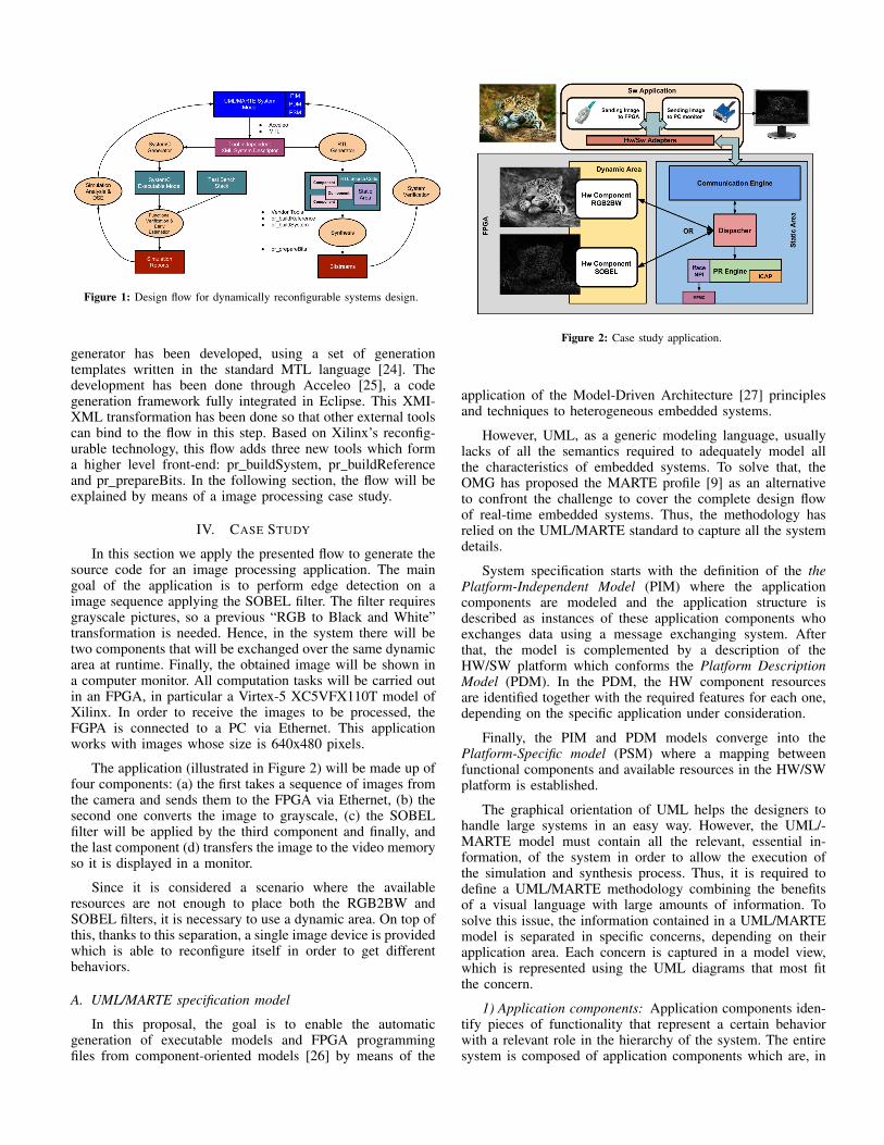
Figure 1: Design flow for dynamically reconfigurable systems design.
generator has been developed, using a set of generationtemplates written in the standard MTL language [24]. Thedevelopment has been done through Acceleo [25], a codegeneration framework fully integrated in Eclipse. This XMI-XML transformation has been done so that other external toolscan bind to the flow in this step. Based on Xilinx’s reconfig-urable technology, this flow adds three new tools which forma higher level front-end: pr buildSystem, pr buildReferenceand pr prepareBits. In the following section, the flow will beexplained by means of a image processing case study.
IV. CASE STUDY
In this section we apply the presented flow to generate thesource code for an image processing application. The maingoal of the application is to perform edge detection on aimage sequence applying the SOBEL filter. The filter requiresgrayscale pictures, so a previous “RGB to Black and White”transformation is needed. Hence, in the system there will betwo components that will be exchanged over the same dynamicarea at runtime. Finally, the obtained image will be shown ina computer monitor. All computation tasks will be carried outin an FPGA, in particular a Virtex-5 XC5VFX110T model ofXilinx. In order to receive the images to be processed, theFGPA is connected to a PC via Ethernet. This applicationworks with images whose size is 640x480 pixels.
The application (illustrated in Figure 2) will be made up offour components: (a) the first takes a sequence of images fromthe camera and sends them to the FPGA via Ethernet, (b) thesecond one converts the image to grayscale, (c) the SOBELfilter will be applied by the third component and finally, andthe last component (d) transfers the image to the video memoryso it is displayed in a monitor.
Since it is considered a scenario where the availableresources are not enough to place both the RGB2BW andSOBEL filters, it is necessary to use a dynamic area. On top ofthis, thanks to this separation, a single image device is providedwhich is able to reconfigure itself in order to get differentbehaviors.
A. UML/MARTE specification model
In this proposal, the goal is to enable the automaticgeneration of executable models and FPGA programmingfiles from component-oriented models [26] by means of the
Figure 2: Case study application.
application of the Model-Driven Architecture [27] principlesand techniques to heterogeneous embedded systems.
However, UML, as a generic modeling language, usuallylacks of all the semantics required to adequately model allthe characteristics of embedded systems. To solve that, theOMG has proposed the MARTE profile [9] as an alternativeto confront the challenge to cover the complete design flowof real-time embedded systems. Thus, the methodology hasrelied on the UML/MARTE standard to capture all the systemdetails.
System specification starts with the definition of the thePlatform-Independent Model (PIM) where the applicationcomponents are modeled and the application structure isdescribed as instances of these application components whoexchanges data using a message exchanging system. Afterthat, the model is complemented by a description of theHW/SW platform which conforms the Platform DescriptionModel (PDM). In the PDM, the HW component resourcesare identified together with the required features for each one,depending on the specific application under consideration.
Finally, the PIM and PDM models converge into thePlatform-Specific model (PSM) where a mapping betweenfunctional components and available resources in the HW/SWplatform is established.
The graphical orientation of UML helps the designers tohandle large systems in an easy way. However, the UML/-MARTE model must contain all the relevant, essential in-formation, of the system in order to allow the execution ofthe simulation and synthesis process. Thus, it is required todefine a UML/MARTE methodology combining the benefitsof a visual language with large amounts of information. Tosolve this issue, the information contained in a UML/MARTEmodel is separated in specific concerns, depending on theirapplication area. Each concern is captured in a model view,which is represented using the UML diagrams that most fitthe concern.
1) Application components: Application components iden-tify pieces of functionality that represent a certain behaviorwith a relevant role in the hierarchy of the system. The entiresystem is composed of application components which are, in
turn, interconnected. This interconnection is established byservices, grouped in interfaces. In this methodology, the ap-plication components are modeled by the MARTE stereotype<<RtUnit>>. The functionality of each application compo-nent is enclosed in two elements: interfaces and files. The in-terfaces group the services provided/required needed for estab-lishing the data transmission between the application compo-nents. The interfaces are modeled by means of UML interfacesspecified by the MARTE <<ClientServerSpecification>>stereotype.
The case study defines three components but two of themwill be implemented in SW in the main application (Figure3). Each application component has an associated set of codefiles that define the component functionality. These files aremodelled as UML artifacts using the UML standard stereotype<<File>>.
Figure 3: Application Components.
The communication is established using two elements:ports and channels. The ports enclose the interfaces that areprovided or required by the component. The ports are specifiedby the MARTE stereotype <<ClientServerPort>>. Each portcan support only one interface, and it can be specified withthe values provided or required from the attribute kind ofthe ClientServerPort stereotype depending on how this in-terface is used in the component. The system is composedof interconnected instances of application components types(Figure 4). The application instances are connected by linksbetween clients and servers who owns ports implementing acompatible interface. These instances are connected throughUML connectors, linking ports (Figure 4).
Figure 4: Application System structure.
After that, functional components are then mapped to mem-ory spaces (Figure 5), which will be assigned to HW resourcesin the target platform model. Thus, components associatedwith a single memory space are always handled together.Specifically, all the application instances that are realized inHW should be grouped in the same memory space (Figure 5,“rgb2bw” and “sobel”). This association with memory spaces
enables the mapping to non symmetric systems, since themodel ensures that there are no memory access problems.
Figure 5: Memory spaces structure and application mapping.
2) HW/SW platform: The platform where the application isexecuted includes the HW resources and the SW infrastructure.The hardware platform is captured and supported throughMARTE stereotypes of the Hardware Resource Modeling(HRM) subprofile (Figure 6). Processors are modelled withthe stereotype <<HwProcessor>>. The bus communicationelement is also supported through the <<HwBus>> and aswell as different types of memories as instruction cache anddata cache stereotype <<HwCache>> and program memorystereotype <<HwRAM>>. Each stereotype enables the pos-sibility to set the values of different attributes of the platform.
Figure 6: Hw component resources.
The other processing element is the FPGA. The FPGAis modeled by the MARTE stereotype <<HwPLD>>. Inorder to enable the synthesis process, this component definescompulsory properties for its characterization. These propertiesare $device, $package, $speedGrade, $architecture and $period(Figure 7).
Figure 7: FPGA component.
Additional features have to be specified in the FPGA.Specifically, these features are related to the structure of theFPGAs that defines the different areas available to configura-tion. In a composite structure diagram associated to the Hw-PLD component, the different sections of the FPGA are mod-eled as parts typed as <<HwComputingResource>> MARTEstereotype. Then, these parts are specified by the MARTEstereotype <<HwComponent>>. In the attribute position,the localization of each section can be specified. Anotherset of different components considered in the methodologyare the resources for communicating the processing elements.Networks and network interfaces can be included in the HW
model, with the <<HwMedia>> and <<HwEndPoint>>MARTE stereotypes, respectively (Figure 6). According tothe additional properties of the HwEndPoint, different typesof commutations are captured. When the network interfacesincludes the IPAddress property the communication is IPconnection, involving a different synthesis process (Figure 8).When the network interfaces includes the serialPort attribute(Figure 8) the communication is by serial port.
Figure 8: Communication interfaces components.
Regarding the SW infrastructure, the operating system ismodeled by an UML component specified by the stereotype<<OS>>[22]. The attributes associated with this stereotypeare the type of OS (Ubuntu, Fedora, Angstrom, etc.) and thepolicy which defines the process scheduling algorithm (FixedPriority Preemptive, Round Robin, FIFO, EDF, etc.). Finally,when HW and SW components are defined, the target platformis created by using parts typed by the previous HW/SWcomponents interconnected (Figure 9). In addition to that, theallocation of the memory spaces previously defined is captured(Figure 9).
Figure 9: HW/SW platform and memory spaces allocation.
3) Environment: In order to support code generation forevaluation, test benches have to be integrated. To include them,a set of UML components is specified by means of stereotypesincluded in the standard profile UML UTP. The compo-nents which represent environment elements are specified bythe UTP stereotype <<TestComponent>>. These applicationcomponents have the corresponding files associated.
Another component is specified by the UTP stereotype<<TestContext>>. This component defines the structure ofthe environment and the interconnection of environment com-ponents with the system under test. The environment structureis modeled in a UML composite structure diagram associatedwith this TestContext component (Figure 10). This compos-ite structure diagram contains instances of TestComponentspreviously defined connected to a UML property typed bythe component where the application is captured (componentsdefined in Figure 6, Figure 7 and Figure 8). This property is
specified by the UTP stereotype SUT (System Under Test) ascan be seen in Figure 10.
Figure 10: Environment structure.
B. Simulation Branch
The main goal of this step is to model and simulate the finalbehavior of the system at an early stage of the design process.As a result, the designer is provided with accurate measureson the performance of the system. It is the responsibility of thesystem architect to interpret and propose the necessary changesin order to meet the requirements. As a distinctive featureof this work, the reconfigurable process is also consideredfor emulation which gives an enhanced picture of the actualbehavior of the final system.
All this can be achieved keeping the degree of manualintervention in a minimum level. Therefore, a reconfigurablesystem architect is only requested to write the behavior andspecify some temporal parameters of the hardware componentswhich will be deployed in the reconfigurable fabric.
A Reconfigurable Unit (RU) entity is defined as a containerfor the core function of an application component. Bothelements (RU+core function) results in what is called SystemCapplication component. In order to emulate reconfigurability,each SystemC component is compiled as a dynamic library.This way, the programming of the FPGA which results in achange of the behavior of a reconfigurable area is simulated bymeans of loading/unloading the appropriate software library.
The second level of integration has to do with the man-agement of the communication with other components. ACommunication Adapter (CA) is responsible of the adaptationof the low level FIFO interface of the SystemC applicationcomponent to TLM semantics. The new logical layer addsadditional information to the messages to be exchanged; iden-tification key of the message, the logical target address orthe logical source address, for example. Figure 11 graphicallyrepresents the composition of the different abstraction layersfrom the core function to a fully functional system component.
As a result, the simulation step allows connecting notonly a set of components described in the UML/MARTE,but also other type of systems, as long as the specific CAhas been appended. In this way, not only flexibility in thecommunication topology is higher but also it achieves thecapability to communicate with external elements connectingto a TLM bus and which do not belong to the simulationenvironment itself.
Once the components have been designed, it is necessaryto provide a Reconfiguration Manager (rc M) to model all
Figure 11: Communication Adapter (CA) Scheme.
aspects as to the reconfiguration such as the interchangeof functionality (loading or unloading the dynamic libraries)and management of the execution state of the components(start and stop the process). In addition, the rc M providesa communication mechanism which allows carring out thereconfiguration of each component (Figure 12).
Figure 12: Test bench module for system simulation.
After modeling the reconfigurable system using SystemC,a behavior analysis is needed. Taking into account the tempo-ral parameters of the components, reconfiguration latency ordynamic area distribution, the output of this phase provides anadvanced knowledge on system behavior. With this, we canensure that the system meets the user requirements. To get it,a test bench module (TBM) has been included in the SystemCinfrastructure previously described (Figure 12).
TBM offers the ability to inject/receive data to/from thesystem and manage the reconfiguration process. The actionsallow to emulate all possible tasks that may occur in the sys-tem, to evaluate its delays and to simulate different scenariosin order to compare different configurations of the system(Design Space Exploration). If the entire system behaves asexpected, the following step is to implement the system,starting with the construction of the static area.
C. RTL Synthesis Branch
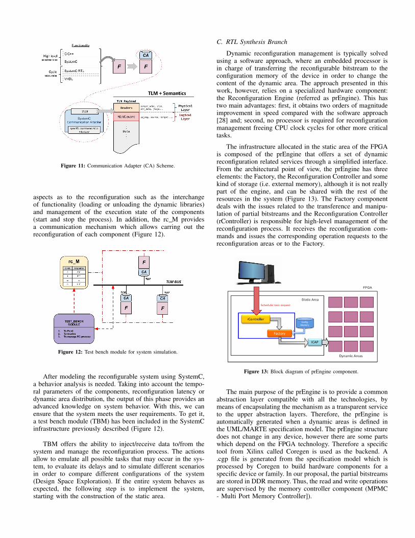
Dynamic reconfiguration management is typically solvedusing a software approach, where an embedded processor isin charge of transferring the reconfigurable bitstream to theconfiguration memory of the device in order to change thecontent of the dynamic area. The approach presented in thiswork, however, relies on a specialized hardware component:the Reconfiguration Engine (referred as prEngine). This hastwo main advantages: first, it obtains two orders of magnitudeimprovement in speed compared with the software approach[28] and; second, no processor is required for reconfigurationmanagement freeing CPU clock cycles for other more criticaltasks.
The infrastructure allocated in the static area of the FPGAis composed of the prEngine that offers a set of dynamicreconfiguration related services through a simplified interface.From the architectural point of view, the prEngine has threeelements: the Factory, the Reconfiguration Controller and somekind of storage (i.e. external memory), although it is not reallypart of the engine, and can be shared with the rest of theresources in the system (Figure 13). The Factory componentdeals with the issues related to the transference and manipu-lation of partial bitstreams and the Reconfiguration Controller(rController) is responsible for high-level management of thereconfiguration process. It receives the reconfiguration com-mands and issues the corresponding operation requests to thereconfiguration areas or to the Factory.
Figure 13: Block diagram of prEngine component.
The main purpose of the prEngine is to provide a commonabstraction layer compatible with all the technologies, bymeans of encapsulating the mechanism as a transparent serviceto the upper abstraction layers. Therefore, the prEngine isautomatically generated when a dynamic areas is defined inthe UML/MARTE specification model. The prEngine structuredoes not change in any device, however there are some partswhich depend on the FPGA technology. Therefore a specifictool from Xilinx called Coregen is used as the backend. A.cgp file is generated from the specification model which isprocessed by Coregen to build hardware components for aspecific device or family. In our proposal, the partial bitstreamsare stored in DDR memory. Thus, the read and write operationsare supervised by the memory controller component (MPMC- Multi Port Memory Controller]).
Once the static part of the design has been identified, thelayout of the dynamic reconfigurable areas must be defined.For each reconfigurable area at least a geometric location,its resources and a name are specified in the UML/MARTEmodel. The geometric location delimits a rectangular shapeusing the bottom-left and top-right slice identifiers.
In the solution proposed, one reconfigurable area is, ac-tually, composed by a grid of smaller sub-areas (see Figure14(a)). These sub-areas are interconnected by generic dataand control signals which enable the communication betweenthem. Also, a reconfigurable area may have one or moreinterconnection channels from/to the static area of the FPGA.The designer must enable or disable these interconnectionschannels and define the type of use they are going to supportwhich can be a bus or point-to-point protocol, for example.Figures 14(b) and 14(c) have channel B disable whereas Figure14(d) has both channels enable with a different configuration.
Figure 14: Hierarchical dynamic areas.
A top file described in VHDL is generated according to thedynamic areas defined in the model. This top file is composedby the static and the dynamic areas as defined in the model.The dynamic areas are treated as a black box, since thedeployment of any component is possible. The assignment offunctionality to areas is known as a configuration definition(described in a *.pxml file). The pr buildReference uses thisconfiguration to
The next step consists in the construction of the filesystem and template files of the reconfigurable project. This isperformed by the pr buildSystem tool, that requires as inputboth the top.ucf file and the static part of the project that canbe obtained from the UML/MARTE model. The tool builds thewrappers and necessary templates to develop dynamic compo-nents and different combinations of reconfigurable modules.
Figure 15 shows an example of a reconfigurable system isdepicted. This tool generates two main directories in the filesystem: regions and generated.
Figure 15: pr buildSystem tool.
After the whole project infrastructure has been created,the developer must assign the components already tested ofthe static area in the corresponding directories. Each directorywill generate a configuration compatible with a certain area.If a new component, not previously designed, is built, it canmake use of the generated template. The next step is to buildan initial configuration (reference configuration) by means ofpr buildReference tool. This configuration is used as both theinitial design to be downloaded, and as a reference for theextraction of the partially reconfigurable areas.
The following step consists in the synthesis of the re-configurable Project to get system bitstreams. Previous tools(pr buildSystem and pr buildReference), generate severalscripts, which help designers to automate this process.
Once all the different bitstreams have been obtained, thelast step consists in modifying them for being used by thefactory component, which is responsible for the partial re-configuration of FPGA. The prepareBits tool removes originalbitstream headers and trashes the data after completing thecommand. The new bitstream is divided into three parts: areduced header, which includes configuration and synchro-nization commands, the bitstream data, and a completioncommand. All these commands are aligned into 32 bits words.The tool is also able to join several partial bitstreams. Theresult is a bitstream, which has a header at beginning offile, then the data of each original bitstream and, finally, thecompletion command.
Finally, a system verification is needed to guarantee thecorrect working of the project, including all process: reconfig-uration, application deployed into a dynamic area, etc., so theuser has to define integration tests to verify the entire system.Due to some tools of Xilinx are beyond of our control, thesystem can be synthesized in a not desired way, In that caseit might be necessary to make modifications to the referenceUML/MARTE model.
V. RESULTS
From the UML/MARTE model, the SystemC simulationprocess builds the entire simulation infrastructure allowingthe behaviour/temporal system evaluation. In this case, allcomponents have associated the time estimation required inthe simulation phase. After analyzing the results of this stage,the simulation log file indicates the following:
• If only RGB2BW filter is used, the estimated perfor-mance is 63.19 frames per second.
• Using dynamic reconfiguration and the SOBEL filter,the performance is reduced around 35.27
• The reconfiguration rate is 180.3 MB/s.
To get an idea of the benefits of using the proposed designflow, the table I shows the lines of code that have beengenerated automatically instead of handwritten.
Elements (VHDL) Lines of code Elements (SystemC) Lines of code
For example, as can be seen in the table, about 8.000 linesof VHDL source code were generated, so that the developersonly have to focus their efforts in the functionality code. In thisscenario, both Hw filters (RGB2BW and SOBEL) has beengenerated from C/C++ using a tool of Xilinx called VivadoHLS. In the first one, the code that has been written by thedeveloper only has 15 lines and the second one 16. Withthese few lines, the Vivado HLS tool generates 3254 lines offunctional code automatically.
VI. CONCLUSION
This work provides a full Eclipse integrated design flowthat allows tocreate dynamically reconfigurable applicationsfrom a high abstraction level (UML/MARTE model), to simu-late different scenarios based-on design space exploration andto implement the final application over a FPGA device.
A hierarchical approach to the reconfiguration problem istaken, where top-level reconfigurable areas can be divided intoa set of smaller independent regions, that can also be freelycomposed at run time. The tools rely on the use of a pr Enginewhich is provided as an independent IP core. The core providesa common abstraction to the reconfiguration process which isdevice independent. New FPGA families can be supported withlittle effort.
VII. ACKNOWLEDGMENT
This work has been partly funded by the Spanish Ministryof Economy and Competitiveness under project REBECCA(TEC2014-58036-C4-1-R) and by the Regional Government ofCastilla-La Mancha under project SAND (PEII 2014 046 P).
REFERENCES
[1] Christophe Bobda, Introduction to Reconfigurable Computing:Architectures, Algorithms, and Applications, isbn 1402060882,9781402060885, Springer Publishing Company, Incorporated. 2007
[2] D. Dye, Partial Reconfiguration of Xilinx FPGAs using ISE DesignSuite” (UG702), Xilinx, 2011.
[3] W. Wolf, High-Performance Embedded Computing. Architectures, ap-plications, and methodologies, Princeton Universit, 2006.
[4] Xilinx, “Partial Reconfiguration User Guide”, Xilinx, 2011.[5] N. Steiner, A. Wood, H. Shojaei, J. Couch, P. Athanas and M. French
Torc: Towards an Open-Source Tool Flow, Nineteenth ACM/SIGDAInternational Symposium on Field-Programmable Gate Arrays, 2011
[6] T. Cervero, S. Lopez, R. Sarmiento, T. Frangieh and P. Athanas Scal-able Models for Autonomous Self-Assembled Reconfigurable Systems,International Conference on ReConFigurable Computing and FPGA,2011.
[7] G. Martin, B.Bailey, A. Piziali. ESL Design and Verification: A Pre-scription for Electronic System Level Methodology (Systems on Silicon).March 9, 2007. ISBN-10: 0123735513.
[8] Y. Vanderperren, W. Mueller, W. Dehaene: UML for Electronic SystemsDesign: A comprehensive overview, Design Automation for EmbeddedSystems, V.12, N.4. December 2008.
[12] Y. Vanderperren, W. Mueller, W. Dehaene. UML for Electronic SystemsDesign: a comprehensive overview. Journal on Design Automation forEmbedded Systems, Springer Verlag, August 2008.
[13] F.Bruschi, E. Di Nitto, D. Sciuto. SystemC Code Generation from UMLModels. Forum on Specification and Design Languages 02.
[14] W.Muller et al. The SATURN approach to sysML-based HW/SWcodesign. IEEE Annual Symposium on VLSI, ISVLSI 2010.
[15] S. Bocchio, E. Riccobene, A. Rosti,P. Scandurra. A SoC design flowbased on UML 2.0 and SystemC. In DAC, Workshop UML-Sock’05.
[16] D. Harel, H. Kugler, and A. Pnueli, “Synthesis revisited: Generatingstatechart models from scenario-based requirements,” Formal Methodsin Software and System Modeling, 2005.
[17] M. Adamski. Design of reconfigurable logic controllers from hierar-chical UML state machines. 2009 4th IEEE Conference on IndustrialElectronics and Applications, ICIEA 2009.
[18] J. Vidal, F. de Lamotte, G. Gogniat, P. Soulard, J.P. Diguet. “ACode-Design Approach for Embedded System Modelling and CodeGeneration with UML and MARTE”. In Proceedings of DATE’09.Dresden. March, 2009.
[19] E. Piel, R. Atitallah, P. Marquet, S. Meftali, S. Niar, A. Etien, J.-L.Dekeyser, P. Boulet: ”Gaspard2: from MARTE to SystemC Simulation”,proc. of the DATE’08 workshop on Modeling and Analysis of Real-Time and Embedded Systems with the MARTE UML profile, 2008.
[20] I.R. Quadri, Yu Huafeng, A. Gamatie, E. Rutten, S. Meftali, J.-L. Dekeyser. Targeting reconfigurable FPGA based SoCs using theUML MARTE profile: from high abstraction levels to code generation.International Journal of Embedded Systems, v 4, n 3-4, p 204-24, 2010.
[21] M. Leite, C.D. Vasconcellos, M.A. Wehrmeister. “Enhancing automaticgeneration of VHDL descriptions from UML/MARTE models”. 12thIEEE International Conference on Industrial Informatics (INDIN), 2014.
[22] H.Posadas, P.Penil, A. Nicolas, E.Villar, “Automatic synthesis ofembedded SW for evaluating physical implementation alternativesfrom UML/MARTE models supporting memory space separation”.Microelectronics Journal. Volume 45, Issue 10, October 2014, Pages1281–1291.
[23] Papyrus webpage http://www.papyrusuml.org[24] MOF Model To Text Transformation Language webpage