BUILDING A GIANT DRAWING MACHINE The build and improvement process off a multi-colour spray-paint wall plotter for performance on the Maker Festival Graduation Project Report Creative Technology - University of Twente Janwillem te Voortwis - S1441620 Supervisor Edwin Dertien July, 2017
Transcript
BUILDING A GIANT DRAWING MACHINE The build and improvement process off a multi-colour spray-paint wall plotter for performance on the Maker Festival Graduation Project Report Creative Technology - University of Twente Janwillem te Voortwis - S1441620 Supervisor Edwin Dertien
July, 2017
Abstract This bachelor thesis project aims at building and improving engagement of a technical art installation for a festival, a giant drawbot, which creates bitmap representations of pictures or paintings using spray-paint. The realisation phase went smoothly by prototyping the main parts of the installation separately and combining them in a final iteration at the end. The initial iteration of the robot proved to be engaging, but can be improved on a number of factors. Finally, a recommendation is made for improvement of the engagement of the installation and its functional parts. multi-colour drawing robot, v-plotter, engagement, spray-paint simulation
1
2
Aknowledgements Special thanks to my supervisor, Edwin Dertien, who offered the opportunity to build this robot and helped in the process of building the installation. Thanks to Claudia Westerveld who helped with some of the concept drawings. The organisers of the Maker Festival, especially Kees de Groot of Planet Art, were so kind to give an opportunity to show this installation on their festival. Thank you for this opportunity. I want to thank Loes, Dick and Freek who helped me very much.
3
4
Table of Contents 1 Introduction 9
1.1 Summary 9
1.2 Problem Statement 9
1.3 Goal & Research Questions 9
2 Background 11
2.1 State-of-the-art 11
2.2 Design rules to improve the engagement rate of an installation on public display 14
2.2.1 Engagement stages 14
2.2.2 Enticement Triggers 14
2.2.3 External Influences 15
2.2.4 Conclusion 16
3 Method 17
3.1 Project Phasing 17
3.2 Stakeholders 17
4 Ideation 19
4.1 Plotter Head Designs 19
4.1.1 Sandwich design 19
4.1.2 A line of spray cans 21
4.1.3 Two rows of spray cans 21
4.1.4 Spray nozzles in other place than cans 21
4.1.5 A carousel with upright spray cans 22
5 Specification 23
5.1 Requirements 23
5.1.1 Must have 23
5.1.2 Should have 23
5.1.3 Could have 23
5.1.4 Won't have 24
5.2 Plotter head Design choice 24
6 Realisation 25
6.1 Prototypes 25
6.1.1 V-plotter with whiteboard 25
6.1.1.1 Design 25
6.1.1.2 Kritzler code 26
6.1.1.3 Developed code 27
6.1.1.4 Testing V-plotter 28
6.1.1.5 Evaluation V-plotter Prototype 28
6.1.2 Plotter Head 29
6.1.2.1 Gear system 29
6.1.2.1.1 Testing gear system 30
5
6.1.2.1.2 Evaluation gear system 31
6.1.2.2 Calibrating stops 31
6.1.2.3 spray-paint Actuator 32
6.1.3 Simulation and Control Software 32
6.1.3.1 Simulation 32
6.1.3.1.1 Pixilate and visualise 33
6.1.3.1.2 colour grabber 34
6.1.3.1.3 Combining the steps 37
6.1.3.2 Interface and Control 37
6.2 Final Design 40
6.2.1 V-plotter 40
6.2.1.1 Chains and Gears 40
6.2.1.2 Motors 40
6.2.1.3 Motor Mounts 40
6.2.1.4 Frame 41
6.2.2 Plotter head 41
6.2.3 Arduino configuration 43
6.2.4 Communication 43
6.2.5 Software 44
6.2.6 Aesthetics 44
6.2.7 Operation 44
7 Evaluation 47
7.1 Testing the installation 47
7.2 Robot at the Maker Festival 49
7.2.1 Observations 49
7.2.2 Questionnaire 51
7.3 Results versus Literature 55
7.4 Evaluation of the requirements 56
7.5 Improving engagement 56
7.5.1 Adding a story 56
7.5.2 Adding interaction 57
7.5.3 Enlarge the actions of the robot 57
7.5.4 Support the performance with actors 57
7.5.5 Best scenario 58
8 Conclusion 59
9 Discussion & Future 61
10 References 63
11 Appendix A - Gantt Chart 65
12 Appendix B - Questionnaire 67
13 Appendix C - Laser cut drawings 69
6
List of Figures Figure Description Page 1 V-plotter concept. 11 2 Using Pythagoras to calculate the length of the "ropes". 11 3 Der Kritzler robot. 12 4 Black Stripes robot 12 5 Laser cut spray-can actuator. 13 6 3d-printed spray-can actuator. 13 7 Drawing of the sandwich design. 20 8 Leonardo da Vinci - War machine. 20 9 Drawing of line design. 21 10 Drawing of "nozzle in other place" design. 22 11 Drawing of carousel design. 22 12 The v-plotter prototype 26 13 Drawings made using kritzler code. 27 14 Areas created by simulation program 28 15 Prototype of the gear system 30 16 Calibration end-stop of plotter head. 31 17 Source image. 33 18 Pixelised image. 33 19 Visualised image. 34 20 Image visualised with drops. 34 21 Colour palette according to most common colours. 34 22 Google Chrome logo. 35 23 Colour palette using hue values. 35 24 Posterised image. 36 25 Color pick process from left to right, posterised image, one colour from
posterised image, corresponding pixels in source, average colour of those pixels.
36
26 Colour palette created by the colour grabber function. 37 27 Visualised image only using grabbed colours. 37 28 Console after start of the program. 38 29 Console after "Picking a Picture". 39 30 Pulley attached to bike gear. 41 31 Motor mount. 41 32 Wooden frame where the motor mounts mount on. 41 33 Backplate of plotter head. 42 34 Inside gear of plotter head assembled. 42 35 Plotter head with spray-paint cans attached. 42 36 Completed installation mounted on tower. 45 37 System overview of the installation. 45 38 First test of the robot. 47 39 Robot drifting to the right. 48 40 First completed mona lisa. 49 41 Second completed Mona Lisa. 49 42 Second and third Mona Lisa in a frame. 49 51 People looking at the drawbot. 46
Tables 1 List of protocol commands. 43 2 Factors for the scenarios 58
7
8
1 Introduction
1.1 Summary The Maker Festival Enschede is a festival for “makers”. A maker is defined as a person that makes or produces something. These makers are people who are closely associated with inventors and creators. The purpose of this festival is to share ideas, knowledge and inspire people to start making themselves. Maker festivals exist since 2006 and are all over the world. 1
The Maker Festival in Enschede started a few years ago. Last year the amount of visitors was not satisfactory, so they have come up with an idea to get more people to the festival.
The organisers of the festival try to get more attention by putting three towers in front of the festival, each six meters high. Every tower is assigned to one technical artist to do with it whatever he/she likes.
One of the towers is assigned to Edwin Dertien who came up with an idea for a spray-paint robot. The proposed concept is to build a large-scale drawing machine that is capable of printing bitmaps in spray-paint pixel dots on the side(s) of this tower. This assignment involves hardware design, software design, interaction design, project organisation, much spray-paint, dirty clothes, festival stress and supervisor management and will result in a cross breed between the Kritzler and Robo-rainbow . The theme of the festival is Leonardo Da 2 3
Vinci, so the design of the robot should be inspired by his work. In the end the robot must be able to make a representation of the Mona Lisa.
1.2 Problem Statement The challenge is to design and build a robot that is capable of printing bitmaps in spray-paint pixel dots in multiple colours. This robot should be able to work on one side of a six-meter-high tower and must be operational before the start of the festival. To be able to finish the robot in time it has some design constraints. One of those constraints is that the robot should move around using a v-plotter design because this is already a proven concept as a robot wall plotter.
1.3 Goal & Research Questions The goal is to make this installation as engaging as possible to attract the most amount of people to the installation. The process of engagement often requires users to begin interacting with something. One cannot rely on a user’s conscious purpose to drive them through the earlier stages of engagement, we need to make the entire pathway enticing [2]. Therefore, I must find the best enticement factors to improve the interaction design process of the installation.
There are three possible outcomes of the interaction design process. The installation can become interactive which means that the user has an effect on the installation but has no creative input. The machine draws what it was programmed to do. Secondly, the installation can also become participatory which means that the user can add something to a collaborative artwork. They have creative input to some degree. Finally, the installation can also become non-interactive, but then it has to be enticing enough as an art piece itself.
1 Maker Faire wikipedia - https://en.wikipedia.org/wiki/Maker_Faire 2 Der Kritzler robot - https://tinkerlog.com/2011/09/02/der-kritzler/ 3 Robo Rainbow - https://www.wired.com/2011/02/graffiti-robot-rainbows/
9
The previous mentioned challenges lead to the following research questions: How to build a V-plotter multi-colour spray-paint robot? How to improve a spray-paint robot on public display to maximise the engagement of the audience? To answer these questions a number of sub questions should be answered during the phases of this graduation project. These sub questions are: RQ1: How to build a V-plotter? RQ2: How to spray multiple colours using one plotter head? RQ3: What are the factors that have an influence on engagement? RQ4: What is the current value of the factors that influence the engagement of the robot? RQ5: How can the experience of the robot be optimised to maximise the engagement rate? Because of time constraints I chose for two main research questions. You could combine the two questions into one. This means that you will incorporate the literature and research scenarios in the designing and build process. I am not able to do this because of time-constraints. The robot needs to be finished in time for the festival and after that the concept will be evaluated. Based on the evaluation recommendations for a design iteration will be given to get a higher engagement rate.
A constraining part of the project could be that the robot is not finished in time for the festival. The robot must be completed first to continue with the research. If I am not able to complete the robot at all I cannot research the ways of improvement. Parts of the robot can be delivered late. This means that the building process would take longer. Most of the parts of the robot are already available from different direct sources.
10
2 Background The background consists of two parts. The first part concerns the robots and mechanisms already out there. This will help in the design process of the robot. The second part elaborates the best enticement factors to improve the enticement rate of the robot.
2.1 State-of-the-art As stated before a V-plotter draw bot is already a proven concept. First a short description will be given on how a V-plotter design works. Since all the following robots that will be discussed feature this design it will be explained beforehand. A v-plotter has a "head" (figure 1) where the drawing tool is located. This head is moved over a 2d plane using two motors. The head is connected to these motors using toothed belt, chain, ropes, etc. The motors can decrease or increase the lengths of these ropes to move it to a certain position. When the robot is started, these ropes should be at a known length so the robot “knows" where the head is. To calculate the lengths of the ropes for a next position Pythagoras law is used, see figure 2. The motors increase or decrease the rope length to the correct calculated length so the head is at the right position.
Moving the head from one point to the next does not have a linear motor profile, unless going straight up or down in the middle of the two motors. The V-construction introduces an error that is caused the radii of the ropes. The way most draw bots solve this problem is by dividing their path into small parts. When the path length is very small this error is reduced to a minimum and can be neglected. This results however in a very choppy motion.
Figure 1: V-plotter concept. Figure 2: Using Pythagoras to calculate the length of the "ropes".
There are already many draw bots out there. A few of these robots will be discussed. For every robot the design instructions that could be used for the project will be elaborated. There are a lot of how-to’s and instructables out there that show you how to build your own v-plotter drawing machine. I won't go into those, I will describe a number of existing examples that represent these. One example is "Der Kritzler”. This robot can scribble drawings using a marker. It is powered by two motors using a toothed belt to move the plotter head. It has a servo to move the marker off and on the surface it's drawing on. The source code of this project is openly available, so this can be used to base the software of the project upon. The software features a drawing conversion tool with two drawing styles and code to control the robot. When looking into this code the earlier discussed problem arose, it solves the non-linearity problem by cutting its path
11
into very small pieces. It uses an input of vector images and breaks these up in a path pattern with very small steps. This results in a robot that makes very slow, rocky movements. I think this is why they call it "Der Kritzler” which translates to “the scribbler”. When using spray-paint you want fast smooth motions to be able to distribute the paint, so the control algorithm does not work for this project.
Figure 3: Der Kritzler robot. - [source] https://tinkerlog.com/2011/09/02/der-kritzler/ Another draw bot is called “Black Stripes” . This robot also works with a marker or pen that can 4
be lifted using a servo. Their software is also open source. When reviewing their robot and code I noticed a different drawing style. This robot uses a variation on a technique called polar-graphing . This drawing style incorporates the non-linearity error into their drawings 5
making the controlling of the robot much easier. One of the motors does not change length during the drawing process. This means that the robot is drawing parts of increasingly bigger circles. This works perfectly for a robot that uses just one colour since all the crossing lines are the same colour. The robot for this project will feature multi-colour spray-paint representation of a picture, so this technique is not really usable.
Figure 4: Black Stripes robot4.
4 Black Stripes robot - https://www.blackstripes.nl/en/products/drawbot/BOTMK1/ 5 What is a polar graph? - http://www.polargraph.co.uk/whats-a-polargraph/
The robot with the most similarities to the project is “Hektor” . Hektor is a plotter robot that 6
uses spray-paint instead of a marker. It also features a pathfinding algorithm. This is used to control the robot so it can spray well curved on the wall without shaking. This pathfinding software is open source. The control of the robot is fast and smooth, very good for spray-painting purposes. Unfortunately the control code is not openly available. The spray head has a mechanism to open and close the spray can. This mechanism and its qualities will be discussed later among others. Unfortunately there has not yet been found a machine or algorithm that overcomes this non-linearity problem and that uses multiple colours. There are ways to solve the non-linearity problem by creating paths for the motor to follow in a smooth motion. Piecewise approximation of the path is a very common approach. This technique works by dividing the to be travelled path in a high number of small distances. These small paths are calculated separately and added together to form a path to follow by the motors. By calculating very small distances, the non-linearity factor can be negated. This is something that can be implemented in design and development phase. In the final installation spray-paint cans need to be actuated. There are already some designs out there that enable this action. Hektor has a laser cut box where the spray-paint can is placed in. On top of this box is a lever that presses down on the nozzle of the spray-paint can. This lever is actuated using a solenoid trigger.
Another design by an unknown designer (see figure 5) has the servo directly on the spray nozzle. The servo functions as a camshaft. When the servo turns a part of the cam wheel presses down the nozzle opening the valve.
The final design is 3d printed (see figure 6) and uses a lever system to open the valve of the spray-paint can. It has a ring that can be attached to the can. This ring holds the servo and a lever connected to it via a hinge. The advantage of this design over the other two is that it is easily attachable to the can and can be adjusted to the needs of the project.
2.2 Design rules to improve the engagement rate of an installation on public display The objective is to find the factors to consider in the design process to maximise the engagement rate of the installation. Since the interaction is done with an art installation on public display the research will be
done in this context. The enticement factors must be applicable either to an art installation or another installation on public display. The first part focusses on the stages of engagement. The different stages are explored and a
description is given. The second part focusses on the triggers to entice people to use an installation and different triggers are analysed and defined. Finally, external influences on those triggers will be examined and characterised.
2.2.1 Engagement stages There are three key stages of engagement [3-7]. The first key stage is the 'Unaware' stage in which the user is not aware of the installation who is also referred to as a passer-by. The user does not notice the installation or the interaction possibilities. The second stage is the Focal Aware stage in which the user notices the installation and gets an initial understanding. The initial understanding of a public display system is based on peripheral awareness, i.e. fleeting glances from a distance [3]. The user can transition to the third stage, namely the Participation phase where the user is actively interacting with the installation or public display. One of the aforementioned three key stages can be divided into sub-stages. The Focal
aware stage consists of two sub-stages, becoming a viewer and an understanding user [5-6]. A viewer has become focal aware, but does not understand the interactivity yet. They are either seeing other people using the installation or watching instructions from the installation. The understanding user is still not actively participating, but does understand the form of interaction with the installation. The transition between these phases features a certain threshold. This threshold can be
high or low depending on external influences [3][6]. These external influences will be reflected upon later. To overcome these thresholds, you can use enticement to let the user better overcome these thresholds [3][6]. Every threshold is equally important, if users do not transition to the next stage the user becomes a dropout. To make sure the engagement rate of the proposed installation is as high as possible the
user must be able to transition with ease between the engagement stages and must always be able to drop-out. The thresholds between the stages must be kept as low as possible to maximise the ease of transaction between the phases. Enticement factors should be used to make the users overcome the thresholds. An optimum level needs to be found in the use of external influences and enticement triggers.
2.2.2 Enticement Triggers There are several methods to improve the enticement of an installation. The most common way of incitement improvement is a low threshold for participation [3][8][9]. The low threshold is not an enticement trigger itself, enticement triggers can be used to lower this threshold. This threshold should not be too big to begin with, or else enticement triggers are not enough to overcome the threshold.
14
The bar could be very high when, for example, every user first should fill out a form to be able to participate. The interaction should be easily understood and should allow users to leave easily without any repercussion [5]. When these internal factors create a threshold that is too high for participation, enticement triggers will not help to transition users to the participation stage. Another way to improve enticement is to enhance the two most important factors for
enticement, motivation and curiosity [5][8]. When a user is curious and/or motivated, the threshold to transition to the next engagement phase will lower. Triggers to improve curiosity are exploration, humour, discovery, control, captivation,
fantasy and submission [8]. Exploration is about the exploration of the installation or an object and users analyse the installation to understand it. The participation should look fun, amusing and joyful to improve the humour trigger. Closely related to exploration is discovery where exploration is more related to understanding and the discovery is associated with encountering something new and amazing. The feeling of being in control of the installation, forgetting one's’ surroundings (captivation), an imagined experience (fantasy) and being part of a larger structure (submission) are also important factors. When designing the installation, these factors should be taken into account to create the most stimulating installation for curiosity. The motivation can be divided into two parts, internal motivation and external motivation.
Internal being the aesthetics [3][8][9], visual cues [6][8], audio cues [8][10] and interaction possibilities [8]. External motivators are initial observations and encouragement by others [5][8]. Combining the triggers that improve motivation and curiosity the most important one is
aesthetics. The installation must look visually pleasing and the design must include factors that increase the curiosity of the viewer. The installation must have a low participation threshold to begin with.
2.2.3 External Influences The thresholds between engagement stages are influenced by several external factors. The place of an installation is an important factor [3-7][9][11]. Place is defined as the context in which the installation is placed and can be described by certain factors. Not all factors are known, but a number of these factors appear to have influence on the engagement rate of an installation. Two factors that are related to each other are familiarity and comfortability of a place. When
a person is uncomfortable and or unfamiliar with a place it increases the threshold to participate. The same holds for the opposite, if someone is comfortable and or familiar with a place it lowers the threshold. Another factor that influences people is social embarrassment. This effect occurs when an
installation with interaction is placed in public. The people interacting with the installation have to perform for the crowd around the installation. Some people might feel embarrassed performing for other people, hence the term social embarrassment. In a very public space like a city square, this factor is very high since there are a lot of people watching. Tranquil places do not embarrass people that much. The social embarrassment raises the threshold for participation. One way to reduce the embarrassment factor is to make the interaction collaborative. When multiple people are interacting at the same time people feel less embarrassed. Social learning through passive observation is a factor that benefits from public spaces
unlike social embarrassment. Passive observation allows a spectator to see possible manipulations and their effects, reducing the need for trial and error exploration and allowing time to understand the mechanisms and decide whether to participate [11]. When people have
15
the possibility to observe other people that are interacting with the installation it lowers the threshold for participation. This can introduce another unwanted comfort factor. When creating the option to passively observe the installation from a comfortable seating area the people can choose the comfort over participating resulting in no engagement. The factor that seems to have the best positive effect is the so-called “licence to play”.
Playful places like playgrounds, skate parks, museums etc. allow people to interact with the installation not judged by others; a licence to play. When people feel not judged by others they do not feel embarrassed and are more likely to interact with the installation. The engagement rate in these places is higher than the places that do not have the licence to play. All the previous factors have influence on place, the context of the environment. Another
very important factor is space, the opportunity for engagement of an environment. Place attaches social meaning to a space; people enact social norms through their activity [11]. Space is created by the habits of people, their walking routes, their routines etc. When placing an installation on a very busy walking route you have a great space, because there is lots of opportunity for interaction by the people that walk by. Together, space and place form the description of the environment. It is important to find a good space which is created by other people. Place can be altered to suit the installation best, for example a seating area is put near the installation to boost the social learning factor. When designing the proposed installation, the space and place are very important since
they influence the participation thresholds. If the installation is placed in a poor space and or place the enticement factors might not be enough to overcome the thresholds. Not only should the installation have good enticement factors but also good space and place.
2.2.4 Conclusion To improve the engagement rate, the enticement triggers and external influences are equally important. The external influences affect the initial height of the participation threshold and the enticement triggers lower this threshold. When one of these two factors is not properly designed the participation threshold is not exceeded. If the external influences are not considered properly the threshold is too high to overcome. When the enticement triggers aren't properly used, it creates confusion and the threshold is not overcome. Opportunity to interact with the installation is created by the space the installation is placed
in. Space cannot be designed, so it is key to find a good space. The place associated with the space can be altered to improve the engagement rate. A very public space increases the social embarrassment factor and the participation threshold. If the space is too remote there is no opportunity for engagement, so a nice middle ground must be found for the space. Favourable is a space with a licence to play, this massively lowers the threshold for participation. To improve the social learning factor an area needs to be created where the installation can
be watched from a distance. Through passive observation people learn how to interact and might do so. By creating this space the threshold for participation is lowered. This space should not be too comfortable since this might withhold the people from interacting. Key is keeping the thresholds low and using enticement triggers to overcome those
thresholds. Auditory and visual cues can be used to get the attention of the passer-by. The design of the installation should incorporate the factors that boost curiosity and motivation. If these factors are taken into account it will increase the engagement rate.
16
3 Method
3.1 Project Phasing The project is structured using the design process for Creative Technology[12]. These phases are ideation, specification, realisation and evaluation. The ideation phase consists of reading literature, searching related products and brainstorming for ideas. Because the robot needed to be operational in time for the Maker Festival the ideation phase has to be very short. The idea was already determined and design constraints were in place, this enables for a short ideation phase. The literature research was done in parallel with the other phases. This is where the project differs from the Creative Technology design process. There will be no time to first research and then design based on that research. The research done will be used in the evaluation and recommendations for future iterations.
In the specification phase the requirements are gathered. Prototyping and constructing the installation is done in the realisation phase. Finally, the evaluation phase evaluates the installation. In this phase is checked if the requirements are implemented. The installation will be tested on the maker festival and observations of the performance of the installation is discussed. These observations in combination with the literature research form recommendations for improvements for a future iteration.
With the design process as guideline a Gantt Chart is made. This chart clearly identifies the phases, activities and duration of these activities. The Gantt Chart can be found in Appendix A .
3.2 Stakeholders In the next section the stakeholders of this project are described. These are stakeholders that are interested in the realisation of the project. The biggest group of stakeholders consist of all persons that visit the festival or simply pass by the installation. These people can come from all ethnicities and have all kinds of moral values. It is hard to predict where these people come from and how they will react to certain situations. These facts make it a difficult group to design for. Because this group has great diversity it makes it challenging to take into account all the different impairments, views and ethnicities of all those people. These people interact with the installation in different ways and can affect the person in a positive or negative way.
The most important stakeholder is the artist. The artist is the creator of the idea of the installation and his or her name is associated with the installation. All the thoughts, opinions and reviews about the installation will be connected to the artist. The success of the installation results in the revenues the artist is making and the exposure he or she is getting. If the installation is very in demand, the artist can make money by placing the installation on multiple locations and get more exposure of his or her ideas.
The artist and the engineer work together and have similar roles. The name of the engineer is associated with the installation, so all thoughts, opinions and reviews as well. The success of the installation also results in revenues. But more exposure means a better entry for his or her portfolio and not so much more exposure of ideas. The ideas for the installation are most of the
17
time created by the artist. The ingenuity and build quality are the factors the builder is responsible for.
The installation is placed on the Maker Festival Twente. This will be the first time the installation is placed on public display. All associations made with the installation will connect to the Maker Festival. All the pieces presented on the Maker Festival should fit in the same theme. Success of an exhibition depends on all the individual pieces. If one of the pieces does not perform well it will affect the whole exhibition. The Maker Festival wants a piece that performs well and fits in the theme of the exhibition. The installation can bring a positive or negative impact to the festival.
This project is done as a graduation project for Creative Technology on the University of Twente, so some publications are associated with the university. The views and performance of the installation presented in these publications can influence the image of the university in a positive or negative way.
The last stakeholder is the municipality of Enschede. The installation is placed in a public area in Enschede. People who pass by and do not know about the festival it is featured on associate the installation with the municipality. The views of these people about this installation will influence their opinion on Enschede.
18
4 Ideation This phase also consists of the state-of-the-art and relevant literature research. These subjects are already discussed in chapter 2 . This chapter will focus on the ideation of the idea and will continue into the specification phase to come to a final concept.
The concept was already considered by the artist. A description of the idea and his view on the project were given by the artist. This is already presented in the summary. In a number of meetings with the artist the idea was refined and specific goals were set. These goals will be discussed in the next section.
In the meetings the general direction of the project was discussed and some quick initial designs were reviewed. Since the v-plotter is already a proven concept not much attention was given to this part of the robot. For the plotter head a number of designs were made and discussed. Also the need for a simulation program was addressed.
4.1 Plotter Head Designs All the designs are made with some things in mind. The plotter head must be able to be hung from chains and the spray-paint cans must be upright when spraying. spray-paint cans will not function properly when not upright because of the propellant. The designs must have room for at least eight spray-paint cans. The choice for this number will be explained later in the simulation software part. Since the simulation software was done parallel to the plotter head design the choice for eight different colours was based on the outcome of the simulation software. And finally all the designs must incorporate room for spray-paint can actuators. A decision has been made for an actuator on every spray can. The amount of cans is low,
there is no limit for the amount of servos or other actuators to be used. When making a central actuating system where every spray-paint can comes by to be actuated problems are introduced that do not exist with the proposed system. A central system introduces alignment issues, a paint can needs to be exactly positioned under an actuator to function. When it is slightly of it will not actuate. The nozzle of the paint can might turn and not spray in the right direction. With a fixed system on top of the paint can the nozzle is always in the right place and not able to turn. The central system adds complexity to the design, the design must be able to move the paint cans under an actuator and remove them after spraying. A fixed system on top of every paint can reduces complexity and increases reliability.
4.1.1 Sandwich design The design consist of a planetary gear system with the centre gear missing sandwiched between two plates. Inspiration for this design came from one of the war machines of Leonardo da Vinci displayed in figure 8. The big inside gear is kept in place by wheels mounted on the outside plates. One of the planet gears is driven by a stepper motor. This gear system with a hole in the middle was needed to be able to fit the electronics and create a centre place for all the wiring of the actuators of the spray cans to go to. All the spray-paint cans are mounted on the big inside gear. Each spray can has an actuator to activate the nozzle. At startup the gear needs to be calibrated to a start position. From that position it can rotate until the right spray-paint can is at the bottom position. Now the can is upright and in a centre position. The chains are mounted as high as possible to keep the centre of weight low. This design is not very scalable. It needs a
19
certain diameter to work mechanically and increases the surface area very much when increasing the diameter.
Figure 7: Drawing of the sandwich design.
Figure 8: Leonardo da Vinci - War machine . 9
9 Source war machine - http://www.bbc.co.uk/history/worldwars/wwone/gallery_tank_01.shtml
20
4.1.2 A line of spray cans This is the simplest design. It is a bar with the spray-paint cans mounted on it. Each spray-paint can has an actuator on top of it. The chains are mounted on the sides of the bar to maximise stability of the bar. This design is very light and scalable. The plotter has to compensate for the offset of the spray cans since they are not all located in a centre position.
Figure 9: Drawing of line design.
4.1.3 Two rows of spray cans To reduce the footprint of the previous design the spray-paint cans are mounted in two rows. One row is slightly above the other. This design has a reduced footprint but needs more complex composition with the plotter position. For the previous design the plotter only needs to compensate in the width direction. For this design the plotter needs to compensate in the width and height direction.
4.1.4 Spray nozzles in other place than cans A way to make the compensation of the plotter minimal is to place the spray nozzles as close as possible to each other. This design is much like the line of spray cans, but the nozzles are in a different place. The nozzles are placed on a bracket very close to each other. The spray nozzles are connected to the spray cans via tubes. A 3d printer is used to make additional nozzles that will transfer the paint from the can into a tube. The original nozzles will be placed on the bracket with the other end of the tube fitted to them. Actuating the spray can stays the same as the other designs, by pressing the nozzle on top of the can. The paint is transported through the tube and comes out at the other spray nozzle. With this design the spray nozzles are placed very close to each other so the plotter has to compensate a minimalistic amount.
21
Figure 10: Drawing of "nozzle in other place" design.
4.1.5 A carousel with upright spray cans This design can be compared with a motorised carousel. The spray-paints cans are fixated to a frame that spins around a vertical pin. This frame is a cylinder that is rotated using a stepper at the top. The chains are mounted at the top of the vertical pin and stepper mount. The carousel spins under this mount keeping the centre of weight low. The carousel has a small footprint and is scalable. All the spray nozzles end up in the same place when rotating the carousel. The plotter does not have to compensate for off placed spray-paint cans like in other designs. Each spray-paint can has its own actuator on top of the can.
Figure 11: Drawing of carousel design.
22
5 Specification
5.1 Requirements During the meetings with the artist the requirements became clear. As the concept for the robot was thought through the importance of the features was listed using the MoSCoW method [13]. This method is well known for prioritising requirements. The requirements were divided in the different categories using the MoSCoW method 'based on importance'. Below the categories are listed followed by the requirements.
5.1.1 Must have Obligatory and Critical requirements The robot must be functional before the start of the Maker Festival The robot must draw a bitmap representation of the Mona Lisa using spray-paint The robot must use a v-plotter to move around The printhead of the robot must be able to spray multiple colours of spray-paint The robot must have an interface to control the robot The robot must be safe to operate The robot must be safe for the public The robot must be able to run for long times (finish a big painting)
5.1.2 Should have Not mandatory for the system to work, but important The robot should have an accompanying simulation program. The robot should be able to draw every image loaded in the program The robot should be able to continue with an unfinished drawing The robot must have a resolution high enough to print a recognisable picture
5.1.3 Could have Robot works fine without these requirements, but they are desirable The robot could be able to draw vector based images The robot could have a way of interaction
23
5.1.4 Won't have Least-critical, Lowest-payback, or not appropriate at the time items The robot won’t have an online interface to make a collaborative artwork
5.2 Plotter head Design choice Evaluating the design two factors come into play, feasibility and aesthetics. Feasibility because it must be able to designed, engineered and build in a short time. Aesthetics is a very important factor because the plotter head will be part of an art installation. The installation must appear aesthetically pleasing to improve the enticement factor. On the aesthetic point the designs with spray cans mounted in a line score very poorly. They
are not interesting to look at. On feasibility they score very high, the designs are very simple and easy to implement. The only problem is that when increasing the colour amount, so the number of spray-paint cans, the design becomes very wide. Since the chains are mounted on the outsides of the mount bar an error introduces itself in the plotter algorithm. The plotter algorithm assumes that the chains form a triangle. A wide bar at the end of the chains does not create a triangle, but a flat bottom triangle instead. The algorithm needs to be changed to compensate for this fact. The bar designs also need compensation when changing spray colours. When choosing for a bar design the software needs to change which is not favourable. The other two rotating designs do not need this software change, but they do need additional development for the rotating parts. Based on the aesthetic point the bar designs are not interesting enough to incorporate in
the installation. That leaves the two rotating designs. They score higher on aesthetic but lower on feasibility. They involve a number of engineering challenges. The carousel design is more feasible than the sandwich design since it has less and easier engineering challenges. This is based on experience of the builder and working out the mechanical design to a certain degree. In co-operation with the artist the sandwich design was chosen as most aesthetically
pleasing and interesting. The design features the most moving parts and does not seem too simple. This design is the least feasible to implement. The least feasible does not mean unfeasible, it means that it is harder to implement but not impossible. The reason the choice was made for this design was mostly aesthetically based. Since this plotter head is for an art installation aesthetics plays a big role. An added bonus was that this was the only design inspired by Leonardo da Vinci. The festival the installation is presented on has the theme Leonardo da Vinci. This design also allowed for easy replacement of all the parts. The sandwich design made it able to replace a separate part in the sandwich while keeping all the other still good parts. With all these factors combined the choice was made to implement the sandwich design in the installation.
24
6 Realisation
6.1 Prototypes To start the development process the build project is split up into different to be implemented parts. These parts are the software to control the robot, the V-plotter hardware and the plotter head for the spray-paint cans. The prototypes will be used to test these parts separately before they will be combined in the final development of the robot. Using prototypes you can easily find problems related to a specific part. In the prototype stage you can find the best design to implement in the final robot. For the prototypes and the final installation the Arduino platform will be used. Arduino is a
single-board microcontroller with an accompanying software tool. This microcontroller can be used to read out sensors and actuate the motors. It is a very easy, much used development environment. It allows for fast prototyping and development.
6.1.1 V-plotter with whiteboard There are already implementations out there using a V-plotter. A prototype was made to test the algorithms, accuracy and resolution of a V-plotter.
6.1.1.1 Design Two 23SM056-028-8W-F10-1.3 stepper motors were attached on top of a standing whiteboard, 10
a fixed distance apart. Fitted on the motor shafts were laser cut, 30 tooth pulleys to drive GT2 timing belts. These belts were each 3 meters long and attached to a laser cut printer head that holds a whiteboard marker. The toothed belts go from the printer head over the pulleys and on the other side of the belts there were contra weights to relieve stress on the motors. In this way the weight of the printhead does not have to be hold in place by the motors, the contra weights balances everything.
The two stepper motors were powered by the accompanying MSD-32-2.5 stepper drivers. The drivers worked by setting a direction-pin to control the direction of the motor rotation 11
and a stepper-pin that makes a step every time it detects a pulse. The stepper drivers were controlled using an Arduino Uno and powered using a Dell server power supply running on 12V.
Materials used: 2 23SM056-028-8W-F10-1.3 stepper motor5 2 Boikon motor mount 1 Boikon 40x40 aluminum profile - 120mm long 2 M415C stepper driver 6 1 Arduino Uno 2 GT2 timing belt - 300mm long 2 Laser cut, 32 tooth, GT2, 25mm wide, 10mm bore, pulley
10 Datasheet Motor - http://www.stappenmotor.nl/Datasheets/ShiMotoren/23SM%20F%20serie.pdf 11 Datasheet Driver - http://www.stappenmotor.nl/Datasheets/microstapdrivers%20info/MSD-32V-8.htm
25
Figure 12: The v-plotter prototype.
6.1.1.2 Kritzler code The prototype was first tested using the open source firmware and software of the Kritzler robot . The firmware was downloaded and the necessary parameters were filled in like the distance 12 13
the motors were apart, the number of teeth in the toothed pulley etc. After this was done the code was compiled and uploaded to the Arduino board. Controlling the robot was easy using the Processing software for the Kritzler. You can import SVG vector images into the program. The program turns these images into paths that can be executed by the robot. You can reposition the image on the draw plane and then start the robot. The program turns the vector images in very small steps to minimise the non-linearity problem of the V-plotter. These small steps are sent to the robot to draw. This results in very jerky images.
6.1.1.3 Developed code After testing with the Kritzler code a start was made with the development of own software for the V-plotter. The software is using the basic Pythagoras principle as explained before. The code is built to move the plotter to an absolute position on the whiteboard. This means you can give it an x and y coordinate in millimetres and the plotter head will move towards this spot. For this to word the code is based on the assumption the plotter head starts at a certain calibrated position. For this prototype the calibration position was the spot where both toothed belts measured exactly one meter from plotter head to motor. To calculate the position of the plotter head you need certain fixed parameters. The
distance between the two stepper motors, the number of steps that are in one rotation of the stepper motor and the travel distance of the belt when rotating the motor one rotation. The program keeps track of the stepper position, it reduces and increases the step count if the stepper makes a step. Knowing this stepper position you can deduce the length of the belts. You know the number of steps to turn one revolution and you know the distance of the belt traveled when rotating once. When dividing the current step count by steps per revolution and multiplying this number by the travel distance you get the current length of the belt. And by using Pythagoras theorem you can deduce the x- and y-coordinates of the plotter head. An algorithm was made to calculate the difference between the current plotter head
position and the coordinate it needs to go to. The current stepper distances are known because the program kept track of it. The stepper distances of the position to go to need to be calculated. This can be done using Pythagoras theorem. There is a difference in the calculation for the left stepper and the right stepper. For the left stepper the belt distance is calculated by filling in the x and y as the adjacent sides of the right angle in the Pythagoras theorem. For the right stepper the y is the same but the other variable is the motor distance minus the x-coordinate. This gives the distance of the hypotenuse, this is the length the belt should become. To calculate the difference the distance needs to be converted into steps. This is done by dividing the distance by the travel distance parameter and multiplying by the steps per revolution. To get the difference the current step count needs to be subtracted from the calculated step count. The result is the number of steps the motor needs to make. The direction of the motor is based on the result. If the number is positive the motor turn in one direction and if negative in the other. The calculating steps are done separately for the left and right stepper motor. Now knowing how many steps to take to get to the position that is given the motors can
start working. The amount of steps can differ between the left and right stepper motor. To make sure the steppers arrive at the end position at the same time the motor speeds are adjusted to
27
make this happen. The program sends pulses to the motor controller to make steps and controls a direction pin to change the direction of the motor.
6.1.1.4 Testing V-plotter To test this setup a marker was placed in the plotter head and the commandos were sent to make the plotter follow a grid. The choice for testing with a grid pattern was based on the fact that the final robot would do the same motion. This test was both for testing accuracy and range of the V-plotter. When testing the plotter moving to different positions certain things were observed. When
moving to one side tension on one of the belts was lost resulting in poor resolution. When moving far up both belts would have to much tension resulting in poor resolution. These tests were basically proving the facts stated by a simulation program for resolution of a V-plotter . 14
Usable drawing space with good accuracy and good resolution were located in the white area as seen in figure 14. The other areas were too inaccurate.
Figure 14: Areas created by simulation program. Orange: poor resolution Light Blue: too little tension in one of the lines Dark Blue: too much tension in one of the lines (and poor resolution) White: drawing area candidate
During the tests the belts slipped over the toothed pulleys. This was probably the result of putting much stress on laser cut toothed pulleys. This slippage resulted in loss of resolution. A test to fix this was to add more weights to the plotter head and counterweights. This did not improve the resolution and the slippage problem continued to exist. Within the white drawing area the plotter performed well with a resolution of about a
centimetre off the coordinate point it needed to go to. When moving fast across the whiteboard a sinusoidal motion was added to the plotter head. This decreased the resolution. To get rid of this motion extra weights were added to the plotter head to increase the stability. This extra weight did help to decrease the motion but did not cancel it out completely.
6.1.1.5 Evaluation V-plotter Prototype After testing the prototype some problems arose. The belts slipped over the toothed pulleys, using very commonly GT2 6mm wide belts and laser cut GT2 32 tooth 25mm wide pulleys. The system was tested using various speeds from very slow to fast, but the problem occurred at all speeds. In the final design a system should be used with better traction. A system that does not allow for slippage of a belt, chain or rope. With no slippage the program knows where the plotter head is located and is most accurate.
14 Bill Ola Rasmussen, V Plotter Design - http://2e5.com/plotter/V/design/
The tests showed that almost half of the width of the drawings space is not usable due to poor accuracy. This is unfortunately not remedied. In further designs this fact should be accepted and the width of the plotter should be twice as big as the desired drawing space. For stabilisation of the plotter head adding weight helped. Adding an indefinite amount of
weight is not the solution. The installation would not be able to carry the plotter head if it weighs too much. The right relation should be found in the weight of the plotter head and still being able to move the head. Another way of stabilisation is to keep the centre of weight low. So the weight should be distributed to the bottom of the plotter head.
6.1.2 Plotter Head Since there is no multicolour spray-paint V-plotter robot out there, a way has to be found to make this happen. A couple of engineering challenges need to be worked out to make the chosen sandwich design work. The gear system must be able to rotate without much friction and must be able to bear the weight of eight spray-paint cans. A stepper needs to be incorporated in the gear system. A system needs to be implemented to calibrate the wheel to a starting position.
6.1.2.1 Gear system This gear system design was chosen because this solves all the engineering challenges. A rotating dish is needed with a hole in the middle for all the electronic connections for the actuator servos. The dish must also be driven by a stepper motor. The gear system consists of a big 70 tooth inside gear with small 10 tooth planetary gears
holding the big gear in place resulting in a gear ratio of 7:1. The top planetary gear is connected to a stepper motor of the same type used in the v-plotter with corresponding driver. A first version of the prototype was made from four millimetre wood plates laser cut in the correct shape. The gears were created using an online gear generator . For holding the gears in place 15
stud bolts with 3d printed spacers were used. The spacers made sure the gears were at the right height to make contact with the big inside gear. A front and back plate kept the stud bolts from moving. A number of iterations were needed to get all the gear positions just right to minimise friction. To keep the big inside gear from running of the small gears small wheels were installed on the front and back plate. The wheels sandwich the big inside gear. These wheels in combination with the small gears constrain the gear to prevent it from moving in any other direction than rotational.
6.1.2.1.1 Testing gear system After the first prototype was finished it needed to complete a number of test to function properly in the installation. The gears should run smoothly and perform under full load, so with all the spray-paint cans attached. Rotating the big inside gear must not give much strain on the motor.
A simple test of rotating the gears under no load was performed first. This test consisted of turning the gears with building speeds and changes of direction. The sequence simulates the movements it will be doing when installed in the final installation. In this stage it became clear that all the nuts holding the stud bolts in place must be tightened well. If one came loose it could tighten on the gear assembly and put stress on the gears. This results in the whole gear system getting stuck and putting the motor under much stress. When all the nuts are correctly tightened the gear system runs fine at any reasonable speed. The motor is not under stress and runs freely.
The assembly for the spray-paint cans was not finished during the testing of the gear system. To test the system under full load surrogates in the form of glue clamps. The weight and weight distribution of a glue clamps was about the same as a spray-paint can assembly. For this test the big inside gear was outfitted with eight glue clamps and put through the same sequence as the first test. The gear system holds up to stress, but after a while it became clear that the small gears on the inside of the gears system were not strong enough. The gear connected to the stepper that drives the gear system showed chips in the wood and seemed to slip over the motor axle once in a while. The big inside gear did not show any signs of wear.
A second test was done with off balanced weights. Four of the clamps were put on one side of the big inside gear. The same sequence was run as the previous two times. Turning the wheel did not go as easy as before. When the weight is not properly distributed over the gear the motor has difficulty overcoming a dead point in the rotation sequence. When all the weight is at the bottom the motor has to use more power to get the weight to the top of the plotter head. When the weight is on one side of the plotter head the gears on that side showed more signs of wear. This distribution puts stress on the motor and gear system.
30
6.1.2.1.2 Evaluation gear system A change of material was chosen to overcome the wear and slip problem of the small gears. The wood was not able to stand the wear of the disk rotating under load. Making the small gears out of acrylic will fix the problem. Acrylic is much harder than wood and would not chip or wear as easy. The slip problem was also fixed with this change of material. The driving gear has a much tighter fit over the motor shaft when made out of plexiglass. Wood has a certain flex that made the motor shaft slip under stress. An even better material than acrylic is Delrin. Plexiglass had the tendency to break under
stress, delrin can handle more stress because of its more elastic property. To make a more durable gear system all the gears should be made out of delrin, acrylic or an equally dense material. A decision was made to not do this for this installation. Making the big inside gear out of delrin or acrylic would drive up the cost by a lot and would not add that much to the durability of the installation. The cost of a plate of wood is around four euros and plexiglass more around forty. Aesthetically the plotter head fits better to the Leonardo theme when made out of wood instead of acrylic. Since the small gears are not visible to the public it is not a problem if these are made out of acrylic. After stress testing the gear system no wear was found on the big inside gear so the choice was made to keep this gear out of wood. If the gear would wear out the sandwich design would allow for easy replacement of this part. The plotter head must not be used without proper weight distribution. In the test it became
clear that it puts much stress on the motor and the gear system. The weight must be balanced around the big inside gear. Big weights should be placed on opposite sides of the gear to balance each other out and relieve stress on the motor.
6.1.2.2 Calibrating stops The gear system in the plotter head is used to position the spray-paint cans upright and in a centre position before spraying. To move the wheel a stepper is used to move known distances. A stepper motor moves a fixed distance with each step, so by moving a certain amount of steps the wheel can turn to position a new spray-paint can in the spray position. A stepper motor needs a starting point, therefore a calibration method must be added to the plotter head. In order to detect the index position of the dis a switch has been used, after initial tests with
an LED and LDR as light gate proved unsatisfactory. An Arduino was used to read out the switch and drive the stepper motor. After some testing and altering the code the system was very reliable and precise.
Figure 16: Calibration end-stop of plotter head.
31
6.1.2.3 spray-paint Actuator In the state of the art two types of spray-paint actuators were discussed. A laser cut and a 3d printed version. Both versions operated the spray-paint can using a micro-servo. Each spray-paint can must get its own actuator. So eight of these must fit on the wheel of the plotter head. The 3d-printed version has a smaller footprint than the lasercut one and the design by
yang02 was directly available through Thingiverse . So this design was tested first. The designs 16
were altered a bit to fit the installation and printed out. The printed parts put together and a micro-servo was installed. Actuating the spray-paint
can is done by letting the micro-servo pull down a lever that pushes down on the spray nozzle. After the assembly was put on a spray-paint can a test was done by loading a simple sweep sketch on the Arduino. The first test went so well that the choice was made to use this design in the final installation. The laser cut design had to be redesigned since there were no design files available. This would take time and a valid solution already presented itself.
6.1.3 Simulation and Control Software The development of the software is done in Processing . Processing is an open source 17
programming language that enables fast visual design. The language features multiple tools and modifiers for images and offers a quick way to visualise the simulation for this project. These features makes Processing the ideal tool for the development of the software of the project. The process of making pictures out of spray-paint dots was not done before. A few example outcomes have been made in Photoshop, but this was a very work intensive process. An image needed to be limited to a certain amount of colours and converted to a very low resolution. To keep Photoshop in the workflow of the installation was not favourable. Extra software was needed to be developed that could simulate the outcome of the installation. The programs also needed to give a pallet of colours. This pallet then could be used to get the right colours of spray-paint. After the simulation step was completed and the outcome was found satisfactory, the robot
could be started. This program must not only contain the simulation step but also the robot control. The data created by the simulation must be interpreted and send to the robot by the program. A protocol, control console and workflow needed to be developed. The robot should be able to be controlled from the console, this means moving it around and an option to calibrate. The steps that must be taken after simulation to start printing must be in a logical and easy to understand order. All these requirements need to be taken into consideration when developing the software. The full sources of this project can be found on Github . 18
6.1.3.1 Simulation The simulation consisted of three steps, getting a limited amount of colours, decreasing the pixel count and visualising the image in a way the installation would do. Each step had different approaches. The order in which the colour-decrease and pixel-decrease steps were performed were exchanged a number of times to see what the best result would be.
6.1.3.1.1 Pixilate and visualise A start with the simulation software was made by decreasing the pixel count of an image and displaying it in round dots. The choice to start with this part of the simulation was based on the ease of work and quick results. Pixelating an image was easy to implement and visualising the image is the step that comes last but gives the results closest to what the robot would produce. For pixelating the image a function was written. This function needed a source image and
the number of length and width pixels the image needed to be converted to. A new image was created according to the parameters and returned by the function. To pixelate, the pixels of the source image were divided in a grid with the size of the given width and length parameters. Each square of pixels in the grid corresponds to one pixel in the pixelised image that needs to be returned by the function. A square in the grid contains a number of pixels of the source image that needs to be converted to one colour for the pixel of the pixelised image. The red, green and blue values of every pixel in a square ware added to each other adding red to red, green to green etc. Then these added values were divided by the number of pixels in a square giving the average values. These average values were rounded to a whole number and used as the RGB-value of the corresponding pixel in the pixelised image.
Figure 17: Source image. Figure 18: Pixelised image. When keeping a spray-paint can stationary and spraying for a short amount of time a round dot is created. To visualise the image it is converted into round dots and placed in the configuration as the pixels in the image. For this visualisation a class called Dot was created. This class is important in the printing phase. The grid of dots holds all the information that is needed for the robot. Each dot has a position, a colour to display and a colour id to send to the robot. To create this grid of dots a function called 'addDots' is used. This function needs a image and converts this image in a grid of dots to display. The function loops through the image a pixel at a time. For each pixel a dot is created and the colour of the pixel is transferred to the dot. The dot gets a position in a grid and a predefined size. The parameters for the grid size, spacing between the dots and dot size are fixed and can be altered in the code. When starting with spraying these parameters can be filled in according to the user preferences. spray-paint is very unpredictable. It tends to run and drip uncontrollably. There is no desire
to fix this problem. This random dripping is added to the visualisation. Each spray-paint dot has a chance of getting a trail of paint. The position and length of this trail is randomly generated by the program.
6.1.3.1.2 colour grabber The installation supports a limited number of spray-paint colours. This is because of costs and mechanical limitations. The simulation phase is also used to determine the best amount of colours to use. There are several colour palette generators available online. For these generators you need to upload the photo and you get back a colour palette. This was not favourable because this would complicate the workflow. The generators were not open source so an own colour palette generator was developed. The first approach was to find the most common colours and use these. To find the most
common colours the original un-pixalised image is used. A Hashmap is created for every different colour. A Hashmap stores a collection of objects, each referenced by a key. It is like an array, but Hashmap-elements are accessed by a key instead of a numeric index. The key in this Hashmap is a unique colour in the image stored in a Pvector. A Pvector is a class that is used to easily store components of a vector. Since a pixel colour has three components a Pvector is a good way to store this information. The value in the Hashmap is the number of times this unique colour appears in the image. A function loops through the image pixel by pixel. First a check is made if the colour already appears in the Hashmap, if so this one is added to the value. If not a new entry is made with the colour as key and one as a value. The method of using the most common colours as the colours to paint appeared to not
work for the installation. In the case of the Mona Lisa this method resulted in a number of shades of brown. In this painting a lot of dark colours are used and results in a lot of brown. A second test was used to test the method. The logo of google chrome was used to get the colours from. This logo was easy to find and features a very diverse colour palette. The method worked for the google chrome logo but not for paintings made by Leonardo da Vinci. The most common colours in these paintings did not differ enough from each other.
Figure 21: Colour palette according to most common colours.
34
Figure 22: Google Chrome logo.
To overcome this problem instead of using the RGB-values of the pixels the hue was used. A colour can be converted from RGB-values to hue, saturation and brightness. When using only the hue value a colour is more generalised. The method also works with a Hashmap using the hue value as the key and the number of times it appeared as value. In the value the saturation and brightness data were stored to be used later. When the Hashmap was created not the most occurring colours were chosen for the colour palette. An extra step was added to make sure the colours did differ enough from each other. This step looked at the hue values of the top colours in the Hashmap. If two values were too close to each other one of the colours was not put in the palette. This method had better results than just using the most common colours, but the colours did not differ enough from each other. In the case of the Mona Lisa this method gave other colours but still gave multiple brown tints. The approach of taking a version of the most common colours does not give a satisfactory result.
Figure 23: Colour palette using hue values.
Additional research in creating colour palettes from images revealed a technique that uses machine learning algorithms. This process is called colour quantisation. The algorithm starts by plotting out the colours in three-dimensional space. By starting on random positions in the plot and clustering the colours the algorithm attempts to find the colours that make up a colour palette. By running the algorithm multiple times and weighing the different results with each other the machine learning algorithm returns a colour palette that represents the colours in the image. A machine learning algorithm is a bit out of the scope of the project. Machine learning is complicated and the algorithms need to be trained with lots of data before they function properly. Machine learning does not fit in the scope of this project. The way the algorithm works did give inspiration for another method to find the colour
palette. Colour quantisation is a process used for posterisation. posterisation of an image entails conversion of a continuous gradation of tone to several regions of fewer tones, with abrupt changes from one tone to another. Posterisation reduces the colour depth of an image. Processing has a posterise function to apply to images.
The method to go with was posterisation. When applying a posterised effect to the Mona Lisa and limiting the colours to a very low amount creates an unwanted effect. By limiting the colour depth to for example eight these eight colours are the only possibilities. It does not matter
35
which image you put in these eight colours will come out as the colour palette. The posterisation does convert the image in bigger areas with the same colour.
Figure 17: Source image. Figure 24: Posterised image. To get a colour palette from the source image the posterised image and the source image are compared to each other. The posterised has the right amount of colours but not the original colour depth and the source image has too many colours but the right colour depth. By combining these two a colour palette can be created. To do this the function extractcolourFromImage() was created. The function needs an image
to process and a reference image. The image gets posterised first to the right colour depth. The colour depth can be adjusted by a parameter in the simulation program. The function loops through the posterised image pixel by pixel. Like in the previous methods a Hashmap is used to store the data. The key is the distinct colour in the posterised image. The number of keys is equal to the colour depth of the image. The Hashmap value is a separate addition of the rgb values of the corresponding pixels in the reference image. After all the pixels are processed an average is calculated of the Hashmap value. These averages are added to a colour array to form the colour palette. The function gets an average colour value from the corresponding pixels in the reference image of the areas created by the posterisation effect, illustrated in figure 25.
Figure 25: Color pick process from left to right, posterised image, one colour from posterised image, corresponding pixels in source, average colour of those pixels.
36
Figure 26: Colour palette created by the colour grabber function.
6.1.3.1.3 Combining the steps The colourgrab and pixelate step can be done in different orders. When pixelating an image a lot of colour data is lost. To maintain as much of the original image and colours as possible the colour palette is created first and after that the images is pixelised.
After the colour palette is created these colours can be used to form a final image. The pixelize function decreases the pixel count and now uses an average colour of a square of pixels in the source image to get the colour for pixel in the pixelised image. The image that comes out of this process misses the colour limit step. Now that a colour palette is available this step can be added. After the image is pixelated it goes through a colour matching procedure. This step is added in the the decreasePixels function. After calculating a colour for a pixel in the pixelised image the rgb values are compared to the colour palette. The colour in the palette that is closest to these rgb values is chosen to replace the original colour. This results in an image only using the colours that are in the palette.
Figure 17: source image Figure 19: Visualised image Figure 27: Visualised image only using grabbed
colours
6.1.3.2 Interface and Control The interface to go through the simulation process and to control the robot is kept simple and easy to understand. The steps to take are ordered from top to bottom, this is an intuitive way of going through the steps. These steps are simulation, calibration and printing. At the top the user can pick a picture by clicking the corresponding button. When pressed a
file picker pops up and the user can choose the image file to use as the reference image. After picking the image the program makes a simulation with predefined width and height parameters. The user can alter these parameters in the corresponding fields and then press the button named "resize". When the image is visualised the colour palette and loading wheel are shown. The colour palette can be used to pick the right spay paint colours. The loading wheel in the interface corresponds to the printhead. When loading the spray-paint cans into the robot
37
this loading wheel visualisation is used to guide the user to put the spray cans in the correct slot of the printhead. This concludes the simulation step of the interface. The user can move the printhead around using the control buttons at the bottom of the
interface. These are placed at the bottom because the robot does not always needs to be moved around for calibration, it might already be at the right position. The up and down buttons move the printhead up and down. The leftup and leftdown buttons rotate only the left motor and vice versa for the right. If the plotter head is at the calibration position the user presses the button marked "calibrate" to calibrate the robot and the button turns green. The robot is calibrated and can continue to the next step. If the users starts a new print the button marked "print" can be pressed. The robot starts
printing and can be paused by hitting the print button again. If the user wants to continue a previous stopped print he or she can use the startfrom feature. Before pressing the print button the user can fill in the identification number of the dot to start from. This value is default set to zero to start from the first dot. When printing this value is updated to the identification number of the dot the robot is spraying. If this value is altered before pressing the print button the robot will start with the dot corresponding to this number, skipping all the dots with a lower id.
Figure 28: Console after start of the program.
38
Figure 29: Console after "Picking a Picture".
39
6.2 Final Design After a number of iterations and evaluations of the different prototypes they were ready to be combined into the final design. This meant upscaling the v-plotter and fitting the spray can actuators to the gear system. The Arduinos that control the v-plotter and plotter head need to communicate to the control software. A protocol needs to be developed to do this and the control software altered to send position and colour to the robot.
6.2.1 V-plotter To be able to upscale the plotter a number of parts need to be upgraded. These parts will be discussed separately.
6.2.1.1 Chains and Gears As stated before the belts and toothed gears were not sturdy enough to limit slippage and stretch. For the final design bicycle chains and gears are used to improve the sturdiness of the chain system. The left gear has 19 teeth and the right 18, the fact that they differ will be elaborated upon later. A bicycle chain has no stretch, but it does introduce extra weight. The chains might sag because of their own weight. Nevertheless, the benefit of no stretch was chosen above the sag problem. An added benefit is that the chain gear combo has no slippage.
6.2.1.2 Motors The prototype v-plotter needed to move around a piece of plywood and a whiteboard marker. The full scale installation has a potterhead that weighs around 4 kilos plus the weight of the chains. To cope with this, bigger 23SM112-030-8W-F10-2.5 stepper motors with corresponding 19
MSD-50-5.6 drivers are installed. The previous steppers were 56mm long and produced 1.3 Nm 20
of torque. The bigger motors are 112mm in length and produce 2.5 Nm of torque. The settings for the motor driver are set to 3200 steps per revolution. Microstepping is not needed for precision, but reduces the noise level of the motors significantly. These drivers operate on 24V instead of 12V, so a Basetech BT-305 power supply is used that is set to 24V. When the system 21
is idling it draws a current of 4 amps using up almost 100 Watt. Further iterations might consider using less power hungry components.
6.2.1.3 Motor Mounts A new mount needed to be made to fit the bicycle gears and the bigger stepper motors. Boikon aluminium frames are used to construct a “sandwich” around the motor and gears. A reduction pulley system is fitted to give the overall system more torque. Both pulleys have a pitch of 5mm. The pulley on the motor has 15 teeth and a diameter of 22.73mm. The pulley attached to the bicycle gear has 30 teeth and a diameter of 51mm, resulting in a gear ratio 2:1. A belt with a pitch of 5mm and 15mm width is used to connect the two pulleys. Delrin plates are laser cut to make mounts for standard 608 bearings. The pulley system is fitted to the bicycle gear using the delrin gear mount and a M8 studbolt is used as an axle. The whole assembly is sandwiched between two bearings and the boikon material. The sliding motor mount enables to tighten the belt around the pulleys.
Figure 30:Pulley attached to 19 teeth bike gear. Figure 31: Motor mount with 18 teeth bike gear.
6.2.1.4 Frame Wood is used to make a truss-like frame to come closer to the Leonardo da Vinci aesthetic feel. The frame is fitted with a number of hooks, ropes and pulleys to easily hang it in front of a wall or plate. The motor mounts are fitted to the frame using metal angle-brackets. The controllers for the motors were screwed on the upper beam with some additional computer fans for cooling.
Figure 32: Wooden frame where the motor mounts mount on.
6.2.2 Plotter head The spray-paint actuators were attached to the gear system using metal angle brackets. After fitting all the spray-paint cans and testing the rotation the plotter head felt flimsy. The decision was made to cut the parts for the plotter head out of ten millimeter thick wood instead of four millimeter. Since the plotter head is held together by studbolts the thickness addition was no problem, only some extra spacers needed to be 3d-printed to keep the gears in the right place.
41
With the thicker material the plotter head feels sturdier and less likely to break. No changes were made to the stepper motor and driver setup of the plotter head.
Figure 33: Backplate of plotter head. Figure 34: Inside gear of plotter head assembled.
Figure 35: Plotter head with spray-paint cans attached.
42
6.2.3 Arduino configuration For prototyping the Arduino Uno was used. The final installation features custom boards designed by Edwin Dertien that are able to use the RS485 protocol to communicate over CAT-5 22
cable and use a ATmega168 chip. There are two separate Arduinos, one in the plotter head and one on the frame of the v-plotter. The one in the plotter head controls the rotation of the gear system and the spray-paint actuators. The Arduino mounted on the frame controls the motors of the V-plotter. The code for the gear system and spray-paint actuator prototypes were combined. When
receiving a commando the plotter head rotates to the correct position and activates the corresponding spray-paint actuator. The developed code for the v-plotter prototype already had variable frame size and gear
reduction built in. For upscaling the v-plotter only a number of parameters needed to be changed.
6.2.4 Communication The protocol that is used for communication is developed by Edwin Dertien. It was already used before in an installation that he build and performed good. It was only a small step to implement it in the Arduino and Processing code. It is a very simple protocol using only bytes.
The protocol consist a header, id of the intended receiver, data length, command and a checksum. The header is there for the reader to know where to start reading the message. The two Arduinos are listening to two different ids, so they only respond to the messages intended for them. This enables to daisy chain the two Arduino boards and use only one sender. The datalength is always the same for this protocol. The command consists of three bytes. The first is the action that needs to be performed, and the other two are the parameters. When a parameter is not used a random fill value is used. When an action is done by the Arduino it sends back an command to the control software to let it know it is done. The different commands are listed in table 1. At the end of the message is a checksum is used to make sure the messages come over correctly. A checksum is the sum of the transmitted byte values which can be used for error detection.
Receiver Command Parameters
V-Plotter Relative Position x position, y position
Absolute Position command(up,down,left up,left down,right up,right down), steps
6.2.5 Software The previous discussed protocol was implemented in the control software. A print cyclus was added to the program. This cyclus used the stored dot matrix created by the simulation step as the base to send all the position and colour data to the robot. The cycle started with the first dot sending its position and then started waiting for the response of the v-plotter Arduino. When this response arrived the colour data was sent and another wait period was started for the response of the plotter head Arduino. After receiving this response the cycle would continue to the next dot until it arrived at the last dot in the matrix. After this dot was “sprayed” the program was finished. All the code can be found on Github . 23
6.2.6 Aesthetics Some extra elements were added to the robot to make it fit better to the Leonardo da Vinci theme. Two big wheels that keep the motor brackets in place. The final design was made with Leonardo da Vinci in mind. The frame is made out of wood, bicycle chains are used and the plotter head is inspired on one of Leonardo’s war machines. To keep a bit in the spirit of the makers the counterweights were cola and fanta bottles filled with water. Everything was designed to be open and easy to mechanically understand. The idea was to make it understandable so that it might inspire people to make something like this themselves.
6.2.7 Operation Some of the prototypes require actions before they are able to be used. The V-plotter needs to be calibrated and the plotter head has to turn to its calibration point. These are kept the same in the final iteration. When powering up the robot the plotter head automatically calibrates and awaits instructions from the control software. In the control software you can move around the robot until it is in the calibrate position. After hitting the calibrate button in the interface a picture can be picked and printed. While printing the robot does not need any further assistance.
23 https://github.com/Janwillemtv/drawbot
44
Figure 36: Completed installation mounted on tower.
Figure 37: System overview of the installation.
45
46
7 Evaluation
7.1 Testing the installation After the robot was finished the first test runs were done in the exhibition space XPO in 24
Enschede next to the festival location. This was also the place where the robot was assembled. The first time when the robot started up and moved to the starting position. During the movement the chain skipped of the gears. The gears were positioned slightly off angle, so this made clear that the gears should be aligned properly before starting the robot.
A couple of quick tests were performed on this system. The action performed command was not yet build into the protocol, so the control software send the commands based on a timer. This sometimes resulted in the robot spraying when it was still moving, because the moving took too long and the control software already send the command for spraying. The action performed command appeared to be a necessity for accurate and fast operation of the robot.
Figure 38: First test of the robot.
After these quick tests the robot was mounted outside on the tower for the festival. Inside the exhibition space was not enough room to complete a full painting, so the robot needed to go outside. One side of the tower was covered in wooden plates to form a suitable printing surface. The robot was lifted up using ropes, a winch and a couple of pulleys. From the earlier test appeared that the initial settings were not perfect yet. The dots were too far apart to form a even painted surface. A number of parameters were altered and the robot was tested on the tower. After running for a while the robot was stopped manually, because it was spraying dots off the canvas. The robot had a drift to the right side. The initial thoughts were that is was a fault in the code, so this was checked for errors. A second attempt was done for spraying a full painting with the same result. After a lot of debugging the error appeared to be in the hardware. The left bike gear had 18 teeth and the right one 19, this resulted in the robot drifting to the right.
24 XPO space - http://xpo.nu
47
This error was compensated with some additional code in the control software. Another attempt was done for a full painting and succeeded. After the robot finished the painting no errors were detected and the painting appeared perfectly square.
Figure 39: Robot drifting to the right. Prior to the Maker Festival another event was held, the aki festival. The robot was displayed on the tower it was mounted on and stayed in the same place for the Maker Festival. During the aki festival multiple test paintings were run resulting in the first finished Mona Lisa representation (figure 40). The distance between the pixels was not yet satisfactory, so this was halved. After changing the parameters in the software the second Mona Lisa was created (figure 41). The third Mona Lisa was completed the day after using a different colour scheme, by simply switching out the spray-paint cans in the plotter head (figure 42). The aki festival allowed for multiple tests and fixing small issues. These issues will be elaborated upon in chapter 11, further improvements.
48
Figure 40: First completed mona lisa. Figure 41: Second completed Mona Lisa.
Figure 42: Second and third Mona Lisa in a frame. On the maker festival the planning was to spray two paintings in a day, one in the morning and another one in the afternoon. For the first day this went well and resulted in two fully completed Mona Lisa’s. During the last day of operation the first Mona Lisa completed. But when the second Mona Lisa was almost halfway done the installation stopped. After some debugging no error could be found. The installation needed a restart and this meant losing calibration and there would be no option to finish the current painting. After the restart the installations was performing without errors, but it was too late on the day to start another painting. No real
49
reason was found that caused the stop of the robot, but suspicions were that the power supply failed for a short amount of time due to overheating. Overall the robot performed great finishing seven Mona Lisa’s and a couple of half completed ones. During the festival the plotter head needed only one replacement servo. The process of putting the spray-paint cans correctly in the plotter head could use some improvements, since this takes a lot of time to place the cans correctly. But when the cans were in place no adjustments were needed during the operation of the robot.
7.2 Robot at the Maker Festival The robot was displayed during the maker festival and the prior aki festival. During the this period, observations were made and some people were asked to fill in a questionnaire. The observations will be compared to the literature in section 7.3.
7.2.1 Observations All these things are based on observations made during the maker festival by me or the artist. We were present around the robot at all times when it was “performing”. When the machine was actively painting, lots of people were looking at it. They were figuring out what it was doing. When the first Mona Lisa was printing people were asking what it was doing and we explained. When we put the already finished Mona Lisas in the neighbourhood of the machine (not necessarily next to it) people made the link to these paintings themselves and understood what the machine was doing. This is based on the fact that we did not get any questions about the meaning after we put the paintings up. When the machine finished a painting there were two scenarios. We left the robot hanging above the painting or we removed the robot and left the painting hanging outside. When the robot was still present near the painting people showed more interest than when the robot was not present. People seemed to be more interested in the painting knowing it was made by a machine. If the machine was not near the painting it lost some context and people were less interested in the painting. The biggest amount of people were watching when the machine was operational, one could say this a performance art kind of machine. The machine moves very little when going to the next location to spray a dot. So if the carousel is not turning or spraying, or the machine is not changing its position much, it might look like it is not doing anything. An observation we made is that some people walked by because they simply did not notice the machine doing anything. If the spray carousel turned when someone walked by it immediately caught their attention. So more moving parts or visual and auditory cues might fix this. It did not matter much if the painting was almost finished or not, the amount of people watching was about the same during the whole paint process. The amount depended more on the time of day than the progress of the painting. The view duration was also about the same. When the machine was just starting a new painting they stayed a little longer because they needed more time to understand what the machine was doing. With the finished Mona Lisas near the installation this period was not very long.
50
The artist and me received multiple questions on the workings of the machine, about what kind of electronics and software was used. This might be because we were present at a Maker Festival and attracts people that are interested in these specific things. Or the machine invites people to discover and explore its workings. People trying to understand the machine resulted in a funny observation. Parents, grandparents and others were explaining the workings of the machine to children, significant other or others. This resulted in a hundred different versions, purposes and workings of the machine. Each one had a different story with the same concept. When a big group of people was watching the robot, passers-by were attracted to see what was going on. The people passing by seem to want to know where all those other people are looking at. So a big group of people watching attracts even more people up to a point when the thing they are looking at is not interesting anymore. The robot was designed with Leonardo da Vinci in mind. People were very aware that the robot was making the Mona Lisa, but did not make the link to Leonardo. Most of the people were not informed about the theme of the festival. This might have influence on the ability of the people to link the robot to Leonardo. When the link was explained to the people they immediately understood and pointed out the factors of the robot they thought that fit with Leonardo.
Figure 43: People looking at the drawbot.
7.2.2 Questionnaire The questions were formed using the outcome of the literature research. The questions were based on the factors needed for a good engagement rate. People could fill in the answers on a Likert scale, they can give an answer in the range from Strongly Disagree, Disagree, Neutral, Agree and Strongly Agree. The results will be evaluated and discussed per question. This questionnaire was focused on qualitative results with 11 responses. All suggestions made for improvements will be elaborated upon more in section 7.5. The questionnaire can be found in Appendix B .
51
This question was asked because good aesthetics acts as an internal motivator and enticement trigger. With a average value of 3,5 the people either agreed or were neutral. This means the installation could use some improvement aesthetically, but it is not essential since the result is headed towards agreed, instead of neutral.
To keep the threshold for participation low the installation should be easily understood. The result of this question has an average of 3,7. The majority of the people thought the installation was quickly understandable. So no changes need to be made to make the installation better understandable.
52
Attractiveness is closely related to aesthetically pleasing. With attractiveness the attraction to the installation is described instead of the focus on aesthetics. The results showed an average value of 3,8. The majority of the people thought the installation was attractive. So the design of the installation was pleasing enough to attract people to it.
By measuring how passionate one feels about the robot, a measurement is taken of how related you feel to the robot. With an average value of 3,18 not many people felt passionate. The robot does not relate to the people enough to improve the engagement rate. To relate better to people some things can be done. The robot could create different paintings that relate better to the people or the people could pick a painting. The user does not have much influence on the installation and might result in a low passionate feeling.
53
Curiosity is one of the most important enticement triggers. With a high curiosity the engagement threshold is easily overcome. An average of 4,4 results in people feeling curious or very curious. No changes need to be made to improve this trigger, since it is already strong.
A factor to boost curiosity is the ability to discover. The score for this factor is not very high, a 3,09. This means that overall the people did not see the ability to discover the installation. Since the curiosity is very high this factor is not necessary to improve, but it result in higher engagement if done so. By improving the factor the curiosity is boosted. This can be done by making the working process of the robot more clear or adding additional elements that people can discover.
54
To transition from the first engagement phase to the second high visibility is needed. According to the results, with an average of 4,36, people easily noticed the installation from a distance. This means they effortlessly transitioned from the first to the second phase. No further improvements need to be done regarding the visibility of the installation.
The second biggest enticement trigger is motivation. The majority did feel motivated to experience the installation, but some people did not. To boost motivation visual or auditory cues can be added. Another option is to improve the aesthetics.
7.3 Results versus Literature The current status of the installation does not involve interactivity, but one does not need interactivity to measure the engagement. In the literature research there was a focus on systems that were interactive. Later in the process came the realisation that interaction was not critical for engagement. The engagement rate of the installation could still be analised using the factors described in section 2.2. And by improving these factors users will transition better between the stages, even without the last participation stage.
55
In the current case of the robot engagement can be rated by the number of people watching. Using this as a measurement the observations can be analised using the factors from the literature research. By placing finished painting near the robot to add context, allowed the people to discover the installation themselves. With the discover factor improved the curiosity was boosted and people seemed to be more engaged with the installation. This observation is backed by the fact that when removing the ability to discover, by stopping or removing the robot, the people seemed less interested. Motivation, the other big enticement factor influenced the engagement during operation. As stated in the observations people were easier engaged when seeing the robot move or hearing it making a sound. These are factors that influence the motivation. Some people had a bigger motivation, for example an interest in electronics, they are were more likely to engage with the robot. The place and space of the installation can not be evaluated. These require the participation stage of engagement. But when looking at the research this was a good space. A lot of people were passing by the installation and at the Maker Festival people had a “licence to play”. These are the two most positive external influences on engagement. The place around the installation could have been altered to improve engagement, but this was not necessary because of the missing participation stage. According the results of questionnaire the current engagement state of the robot is quite good. The observations made during the festival back this. When the robot was operating the people passing by were easily engaged. But a number of factors can be improved to boost the enticement triggers and improving engagement even more.
7.4 Evaluation of the requirements The robot was finished before the start of the AKI and Maker Festival. When starting the festival all the “must have” requirements were implemented.
The not mandatory functions, or the “should have” have been implemented, but not all of them work. The simulation program works fine and enables the user to put in every image. A function for continuing an unfinished painting has been added, but only works when the robot is calibrated exactly the same as when the painting was stopped. The calibration of the robot turned out to be a lot harder than expected. This does not matter when spraying a whole painting at once, because the robot has the same small error created by the calibration. But when restarting and re-calibrating the robot the error is significantly different. For the continue function to work the calibration method must be improved.
Unfortunately there was no time to implement the “could have” requirements. As explained in the state-of-the-art the robot has a non-linearity problem when moving around. No solution has been found to overcome this. The control software could be altered to fix this problem the same way the other robots mentioned in the state-of-the-art do. By making the step size between the to be drawn points very small the nonlinearity factor can be negated.
Implementing interaction was desirable, but appeared to be a whole research of its own. When interaction is added it must be included in the design process. There are numerous ways to interact with this robot and research must then be done to see which is best. Simply adding interaction was no option and during the realisation phase this “could have” requirement was quickly turned into a “won’t have” requirement.
56
7.5 Improving engagement For improving the engagement of the installation a number of scenarios were created where either the experience or the robot is altered. These scenarios will be described and discussed how they improve engagement. This then will form a recommendation for a future iteration of the installation. Each scenario focuses on improving a certain factors influencing engagement. Eventually a combination of scenarios might be the best solution.
7.5.1 Adding a story To improve the ability to discover a story can be added to the robot. For example by adding a gallery where the whole build process of the robot is explained and telling a story that Leonardo da Vinci build the robot. The people than have the ability to discover the build of the robot and this adds context. With this story people do not need the context of the already finished paintings to understand the robot, the story will tell them. Another story that can be added is by placing a scanner near the robot that scans a real version of the Mona Lisa. The story would be that the robot is a big forgery machine. It scans in paintings and reproduces them. These are example stories and a lot of other stories can be thought of, but adding a story increases the ability to discover and adds understandability.
7.5.2 Adding interaction Interaction is a broad word and involves a lot of things. The installation can be made interactive on multiple levels. The lowest level would be additional parts of the robot that do not have anything to do with the operation. For example people pressing a button that opens a steam valve. It is related to the robot but does not influence the operation.
A higher level would be that people have to help the robot to operate. The robot is idling until someone is interacting with it. This option is not ideal, since the creation of an artwork already takes a long time and adding this type of interaction only adds time. A way to cope with this time issue is to only involve people at certain points. For example picking a picture to paint.
The highest level of interaction is that people control the robot. For example, they are spraying their drawings through an interface. This is hard to implement and adds extra issues. The problem with this total freedom is that they could add all sorts of racial or political expressions. This can be done in text form or by drawing images. The question here is if people should be prevented to do this or not? On the one hand, it can be seen as censorship and on the other hand people are forbidden to make discriminating statements (at least in the Netherlands). Making these expressions influences most people in a bad way. The platform might feel as an easy gateway to make these racial or political expressions. Nobody knows who put the expressions on the drawing, the robot draws what the users give as an input. The user can remain anonymous when making their statement. Unfortunately, the ability to scan all inputs of users and filter out the bad intentions is not possible yet. The users should be restricted in some way to prevent them from making such expressions. If a user needs to put a lot of effort in making a bad intended statement or expression, it is prevented in a way. It is still possible but less likely to happen.
By adding interaction a extra engagement step is created, so an extra threshold needs to be overcome. But by adding interaction you boost motivation and curiosity. If people are doing something themselves improves their passion for the robot. The combination of enticement factors might cancel out the fact that an extra engagement step is created.
57
7.5.3 Enlarge the actions of the robot The current actions of the robot consist of selecting a dot to spray, moving to that position and spraying that dot. All the things that happen in the software are completely hidden right now. By making these actions clear and enlarge them visually the operation of the robot becomes more clear. For example when having a preview of a painting and after selecting a dot in this preview a signal is visualised to the motors. The motors start moving with big turning gears and a lot of sound. When the position is reached a signal is visualised to the plotter head. The plotter head turns with noise and leds show the colours of the spray-paint. A visual and auditory cue is given when paint is sprayed. This process would repeat until the painting is finished.
By enlarging the actions of the robot the ability to discover is increased and the actions of the robot are better understandable. Context is created by giving a preview of the painting and auditorial and visual cues improve motivation. The aesthetics of the robot might also be boosted in this process.
7.5.4 Support the performance with actors Concluding from the observations the robot is creating performance art. This art form can be enhanced by improving the performance. This can be done by the machine itself or by adding actors. For example during the operation a number of people in coats covered in paint are present. The robot breaks down a couple of times and these actors fix the robot. They have to pull levers rotate wheels etc. to operate the robot.
This adds a lot of visual and auditory cues to the robot, this boosts motivation. It also boost curiosity, the actors help the people to understand the robot and add the ability to discover. But it adds a heavy toll on the actors since a performance takes two hours to complete plus the additional time the actors add to the proces.
7.5.5 Best scenario According to the theoretical analysis of these scenarios there are a couple of factors to take into account. The improvement of engagement, the ease of implementation and the additional research needed. These are rated in table 2, one is highest and five is lowest.
Scenario Improvement Ease to implement
Additional research
Total
Adding story 3 1 3 7
Adding Interaction
1 4 5 10
Enlarge actions 2 3 2 7
Adding actors 3 5 2 10
Table 2: Factors for the scenarios
58
In table X you can see that by adding interaction the engagement is improved the most, but it requires the most additional research and is not that easy to implement. With all factors considered the adding a story and enlarging actions score the same. Adding a story to a robot is very easy to implement but requires a comprehensive and good researched story. The enlarging of the actions is not that easy to implement but does not require that much research.
The scenario that would improve the engagement the most would be the combination of the story and enlarging actions scenario. These are easy to combine since they focus on different parts of the installation.
59
60
8 Conclusion After a realisation phase of five weeks the research question "How to build a V-plotter multi-colour spray-paint robot?" can be answered. Answering the sub questions during the progression of the project helped leading to the final iteration of the robot and the current value of engagement was measured. After evaluating the current engagement value the question "How to improve a spray-paint robot on public display to maximise the engagement rate?" can be answered. This report sets the base for the development of the spray-paint robot and allows for further development. The realisation of the robot was done by splitting up the to be developed parts in different prototypes. This allowed for fast development and debugging. By building the v-plotter on small scale the issues with software and algorithms could be found and fixed easily. This happened because there was focus on one specific component of the robot. The same holds for the prototyping of the plotter head. Developing a simulation prior to the robot helped for planning out the protocol and the actions of the robot. The final iteration only needed minor adjustments after installing all the prototypes and scaling up the v-plotter to full size. The tests on the Maker Festival showed the current engagement rate of the robot. The robot was tested on a number of factors that rate engagement. The robot scored good on aesthetics, capturing attention from a distance, understandability and attractiveness. Factors that could be improved are the opportunity to discover, motivation to experience the installation and the fact that people feel passionate about the installation. Using this as an indication a number of scenarios were introduced that improve the engagement rate. Based on the engagement improvement, additional research required and easiness of implementation a combination of scenarios was suggested. Adding a story to the robot and enlarging the actions of the robot proved to be the best ways to improve the engagement. The suggested changes do need another iteration of the installation by completing the design process cycle another time. This allows for more ideation, realisation and testing if these improvement actually work. Now these design improvements are purely theoretical based. Lastly, during this research, several design and realisation challenges have been faces. These challenges have been described and elaborated in the document, so that other researchers and developers can minimise or avoid these issues.
61
62
9 Discussion & Future An number of improvement have already been introduced in chapter 7. A logical step would be implementing these improvements and test if they work. This document has provided factors that can improve engagement and can be used in future iterations of the robot. Adding interaction to the robot requires a new cycle of the design process. The literature research has already been done, but from there on it needs a new cycle. Creating new ideas and realising the best one.
When improving the robot some things must be taken into the proces. The current version of the robot is not intended for extensive use. Gear parts are made out of wood and need to be made out of more durable materials. The motor mounts should be hang free to make it impossible for the chains to run of the gears. Now if the frame is misaligned the chains can run of the gears. This is prevented when the motor mounts can align themselves. The calibration process is now done manually, when automating this process it would increase accuracy. This is desired when wanting to use the function to continuing on an unfinished painting.
Now the robot is only able to be used outdoors, because of the use of spray-paint cans. A different plotter head could be designed for indoor use that uses a paint gun with compressed air. This does not pollute the air and is safe for indoor use. When using the installation indoors the weather has no influence on the plotter head and improves the quality of the painting.
Installing the spray-paint cans into the plotter head is a tedious and precise task. A better way needs to be found to fit these cans to the plotter head. This can be done by improving the quality of the 3d print or redesigning the spray-paint actuator.
All the observations made on the Maker Festival are subjective, this might influence the quality of the data. To prevent this all observations were discussed between me and the artist. All the observations were agreed upon by both the artist and me. This reduces the objectivity by incorporating both our opinions.
Some of the people that filled in a questionnaire already knew about the installation. They did not see it before, but they knew about the concept. This might have influence on the understandability factor of the installation. The score of this factor was very high, so by deducting the scores from these people the scores were still high enough to be seen as positive.
63
64
10 References [1] E.Dertien et al.,"Highlights in Mechatronic Design Approaches,” In book: Advanced
Mechatronics and MEMS Devices II, pp.41-59, DOI: 10.1007/978-3-319-32180-6_3
[2] D.A. Siegel,"The role of enticing design in usability”,(2012) Interactions, 19 (4), pp. 82-85., DOI: 10.1145/2212877.2212895
[3] Brignull, H., Rogers, Y., "Enticing people to interact with large public displays in
public spaces”,(2003) Proceedings of INTERACT, 3, pp. 17-24
[4] Gonzalo Parra, et al, "Quantifying the interaction stages of a public display campaign in the wild”, In Proceedings of the 8th Nordic Conference on Human-Computer Interaction: Fun, Fast, Foundational (NordiCHI '14). ACM, New York, NY, USA, 757-760. DOI: http://dx.doi.org/10.1145/2639189.2639216
[5] Niels Wouters, et al, "Uncovering the Honeypot Effect: How Audiences Engage with Public Interactive Systems”, In Proceedings of the 2016 ACM Conference on Designing Interactive Systems (DIS '16). ACM, New York, NY, USA, 5-16. DOI: https://doi.org/10.1145/2901790.2901796
[6] Kukka, H. et al, "What makes you click: Exploring visual signals to entice interaction on public displays”, (2013) Conference on Human Factors in Computing Systems - Proceedings, pp. 1699-1708., DOI: 10.1145/2470654.2466225
[7] Jorge C. et al. (2013), "Storytelling and the Use of Social Media in Digital Art Installations" In: Koenitz H., Sezen T.I., Ferri G., Haahr M., Sezen D., C̨atak G. (eds) Interactive Storytelling. ICIDS 2013. Lecture Notes in Computer Science, vol 8230. Springer, Cham, DOI: 10.1007/978-3-319-02756-2_29
[8] Simon, L.U., et al,”Triggers to entice an audience to 'perform as interface' in an interactive installation" (2016) AcademicMindtrek 2016 - Proceedings of the 20th International Academic Mindtrek Conference, art. no. 2994351, pp. 322-330., DOI: 10.1145/2994310.2994351
[9] Ronald Schroeter, et al 2012. People, content, location: sweet spotting urban
screens for situated engagement. In Proceedings of the Designing Interactive Systems Conference (DIS '12). ACM, New York, NY, USA, 146-155. DOI=http://dx.doi.org/10.1145/2317956.2317980
[10] Hannu Kukka, et al. 2016. "Utilizing Audio Cues to Raise Awareness and Entice Interaction on Public Displays”. In Proceedings of the 2016 ACM Conference on Designing Interactive Systems (DIS '16). ACM, New York, NY, USA, 807-811. DOI: https://doi.org/10.1145/2901790.2901856
[11] Imeh Akpan, et al 2013. Exploring the effects of space and place on engagement
with an interactive installation. In Proceedings of the SIGCHI Conference on Human Factors in Computing Systems (CHI '13). ACM, New York, NY, USA, 2213-2222. DOI: https://doi.org/10.1145/2470654.2481306


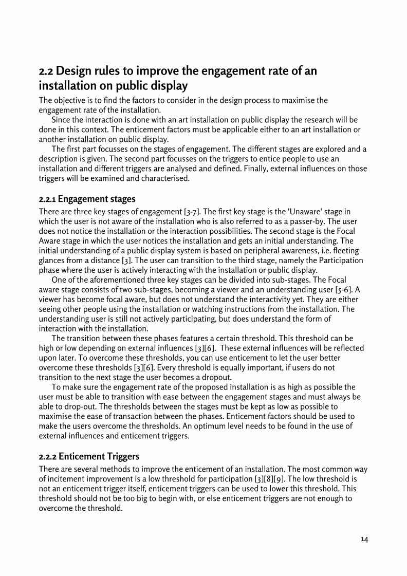


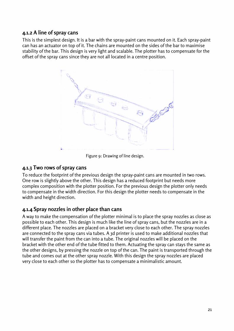


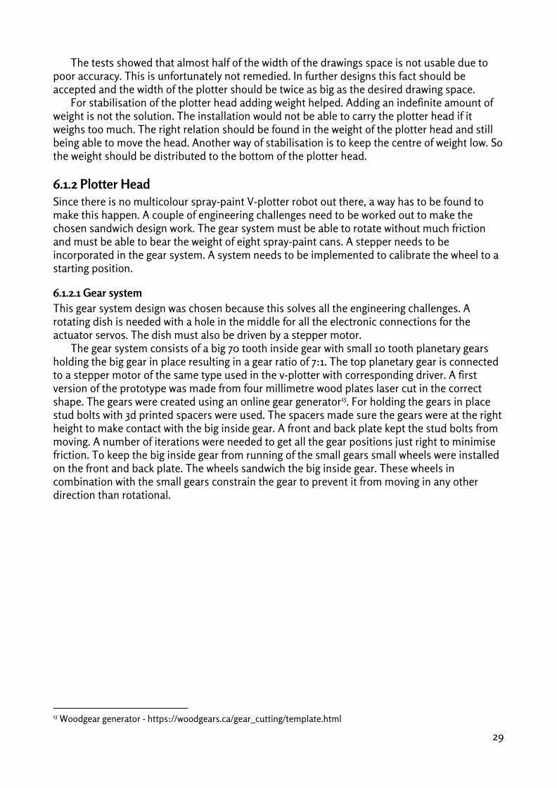
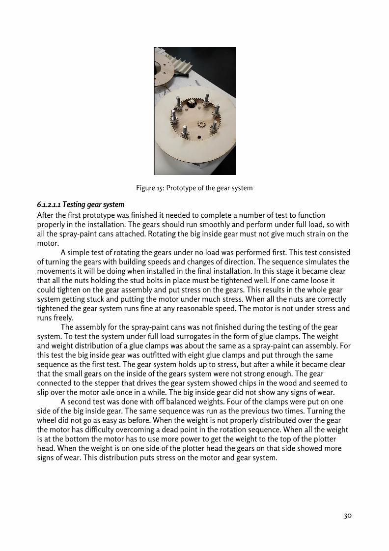

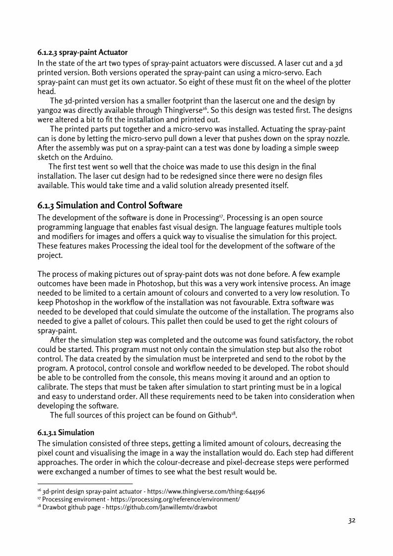
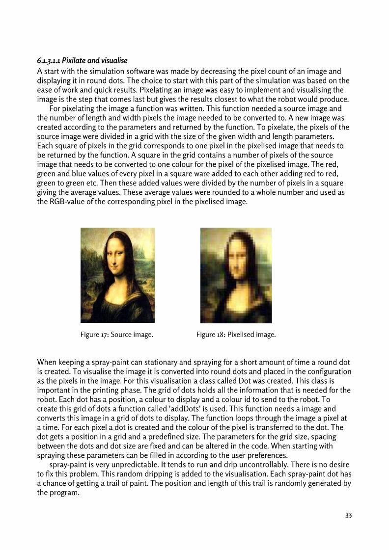
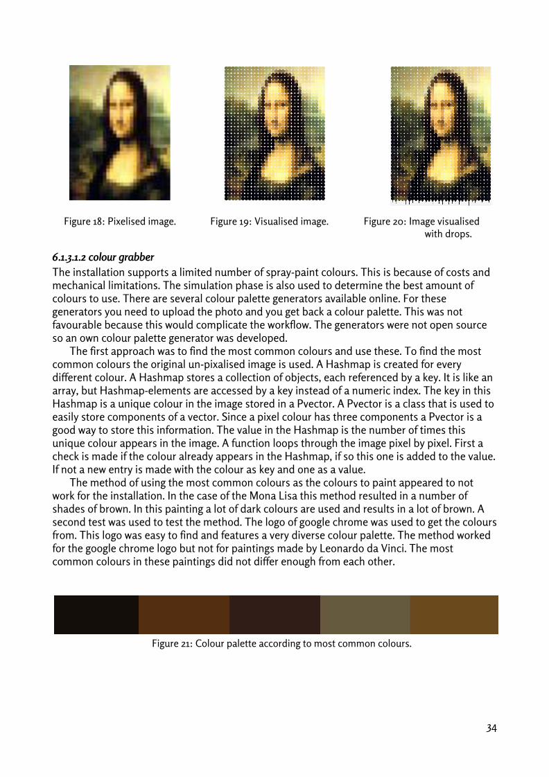


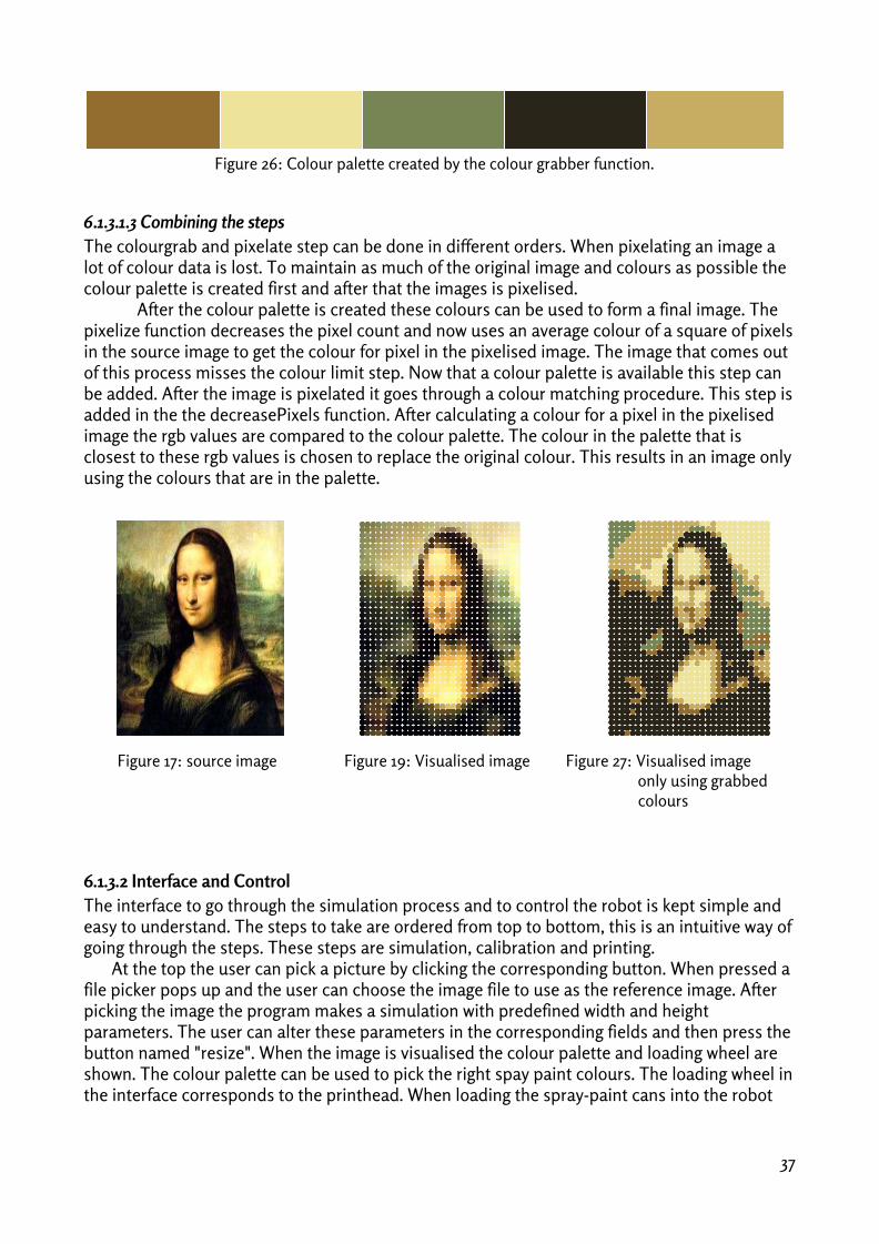
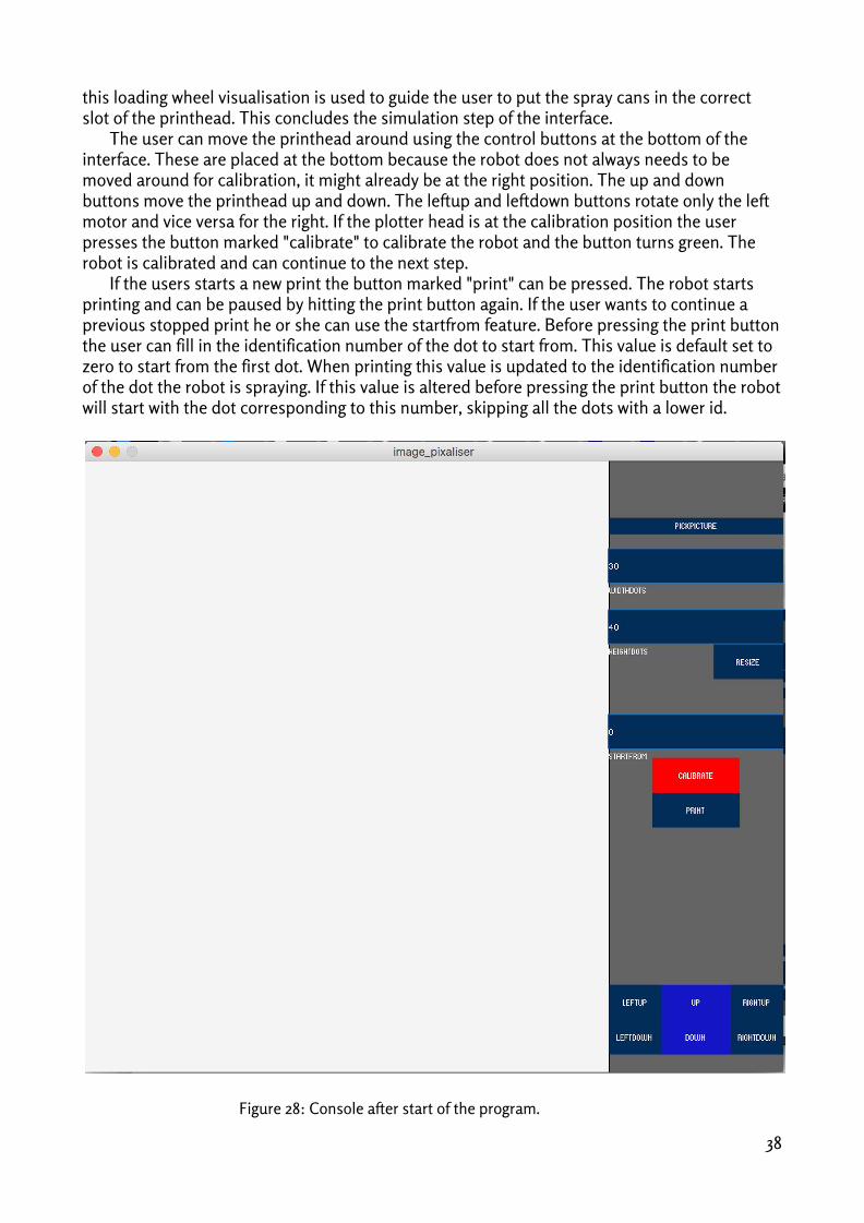
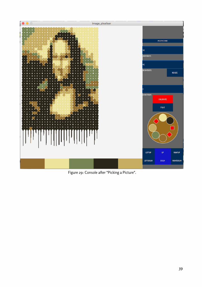

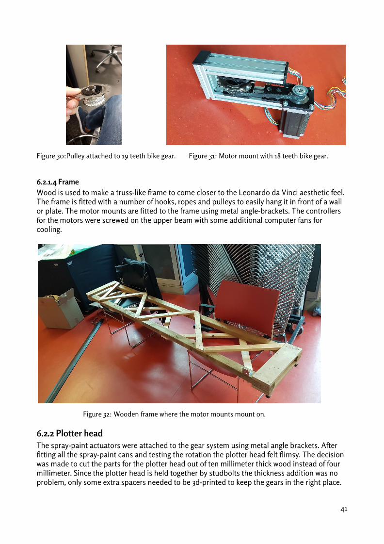

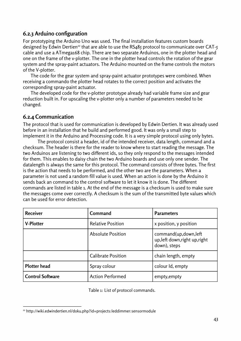


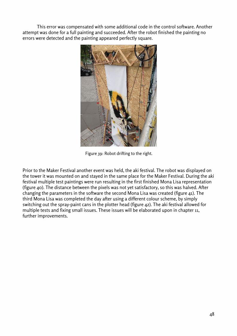


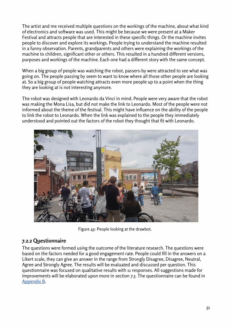

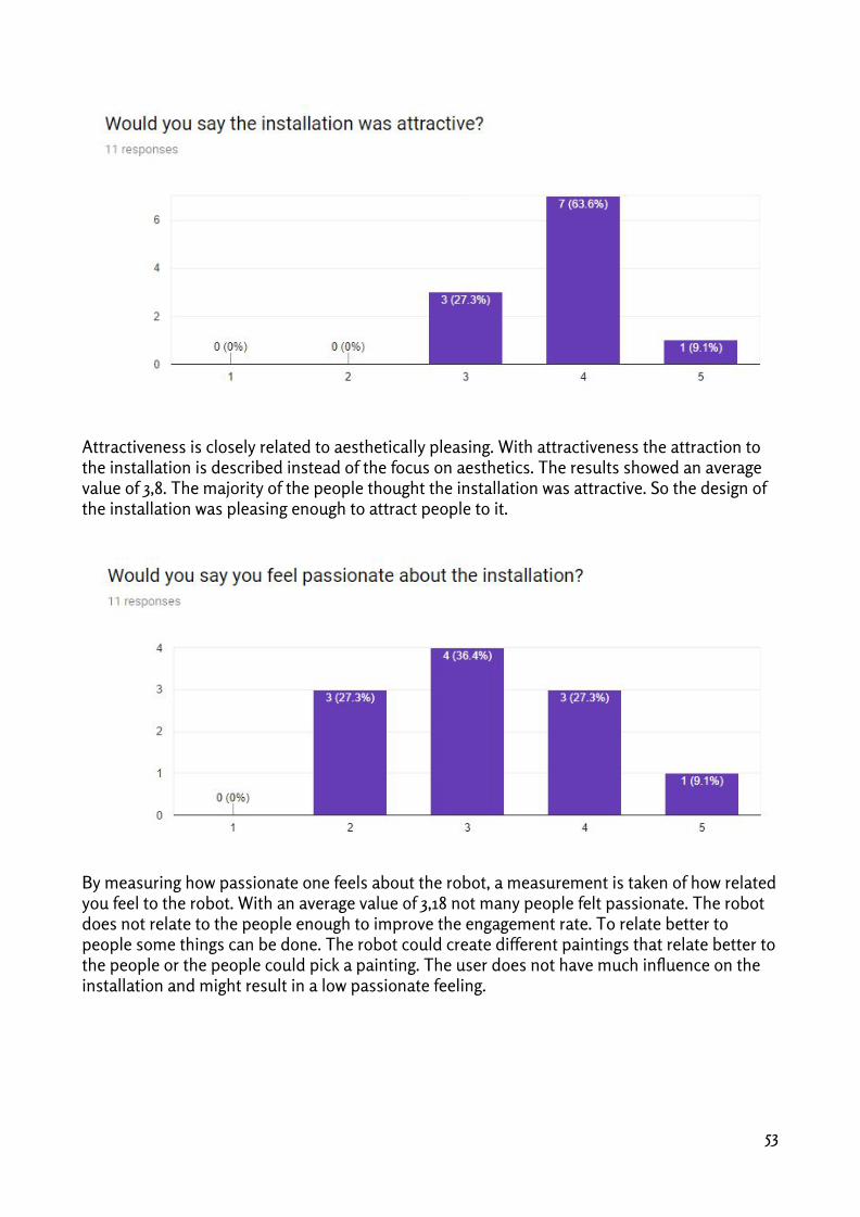


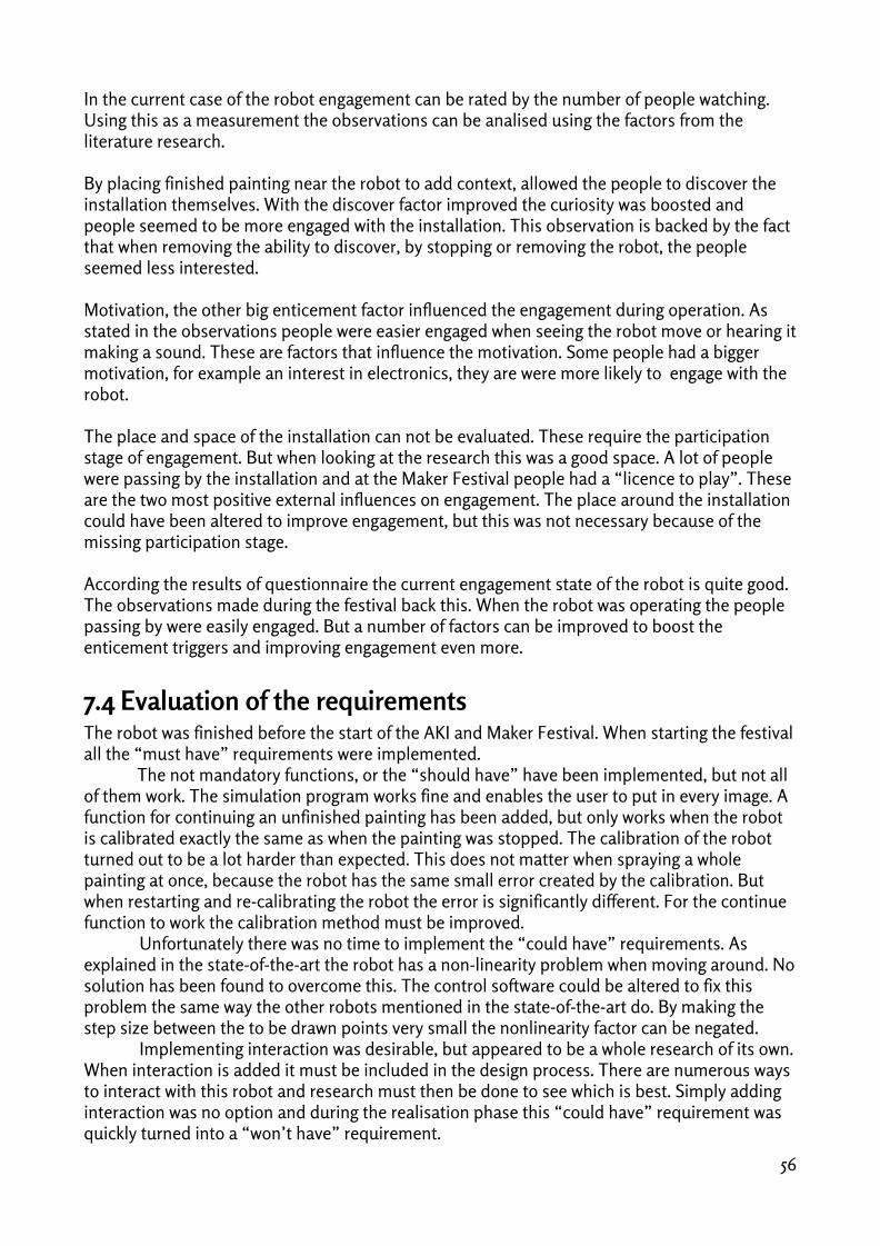


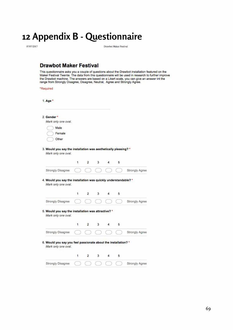

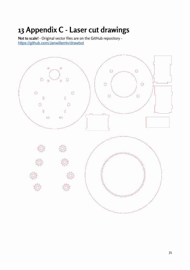


![Sectional Views [Machine Drawing]](https://static.documents.pub/doc/80x56/55cf9ce4550346d033ab706a/sectional-views-machine-drawing.jpg)


![Machine Drawing S3 Mech [Assignment]](https://static.documents.pub/doc/80x56/577cd8e11a28ab9e78a23304/machine-drawing-s3-mech-assignment.jpg)