On a daily basis design blogs and magazines present to the public fascinating images of complex architectures conceived by designers and engineers from all over the world. The wide and rapid development of three-dimensional design software and parametric design allows architects to easily model their complicated dreams. However, it is not unusual for these projects to remain on paper and not turn into actual buildings: cost savings overrun complexity and designers have to reconsider their ideas and dare less with their designs. Luckily, there are several examples of projects that survived the “value-engineering” phase and — thanks to persistent designers, forward-thinking clients and smart engineering solutions — turned into real buildings. This article presents an example of a recently completed project in New York City, VIA 57 West, a large residential building designed by BIG, Bjarke Ingles Group, whose complex facade was made possible thanks to an unusual approach developed by our team of facade engineers at Enclos.
VIA 57 West has been defined by Bjarke Ingels as a court-scraper, a mix between the American skyscraper and the North-European courtyard apartment building. The result is a highrise building contained underneath an attractive south facing sloping double-curved surface punctured in the center by the large courtyard and everywhere else by the wide terraces opening the views to the adjacent Hudson River. An unusual and outstanding shape, posing several structural and performance challenges.
PREVIOUS WORK
When asked to design a facade system for this building we started an in-depth research of built projects presenting both a geometry and a scale similar to the one characterizing VIA 57 West. What was constantly setting apart this building from the many existing projects we found was their context: few of them are in the United States, many are in China or the Middle East, and almost exclusively in contexts where the cost of workmanship is relatively low.
This has a direct impact on the techniques that construction companies adopt to build such complex shapes. The examples we studied presented almost exclusively a stick-built facade, a system that allows almost any shape conceivable to be built but always associated with being labor-intensive and requiring many quality control man-hours. Every component has to be individually checked during construction so that the final geometry achieves the visual look and technical performance expected.
ALESSANDRO RONFINI, LEED AP [BD+C], CPHD
BUILDING COMPLEXITY: DESIGN APPROACH BEHIND A PREFABRICATED DOUBLE-CURVED FACADE
Our team decided to pursue a preassembled, type of construction, subdividing the 84,000 square foot of the sloped facade into manageable prefabricated panels.
In a typical curtainwall system, a vertical facade is divided into modules usually one or two floors tall and 5 to 10 feet wide, a subdivision similar to the one adopted for the panels enclosing the north, east and courtyard elevations of VIA 57 West.
Designed in the shape of a hyperbolic paraboloid, a double-ruled surface whose perpendicular sections are always straight lines, the sloped facade’s geometry did not allow for such a rational subdivision. Using the curves the geometry was built from was impossible, their continuity being constantly challenged by the terrace openings originally imagined by the architect, Bjarke Ingles Group (BIG) (Fig. 6, left).
Before looking at any possible subdivision we started a list of constrains imposed on the pattern of the facade by the design team, to see if, hidden between these limitations, was the solution we were looking for.
The unique shape of VIA 57 West stimulated both the designers and the consultants to find innovative answers for common problems that every building faces. One of the first questions to arise was how to clean and maintain the sloped facade. The solution came in the shape of a wide platform that, transported by a cart along the north edges of the building, would descend along the facade attached to tracks no more than 30 feet apart.
To define these tracks we traced what we termed “gravity lines” (Fig. 6, center), curves of minimum resistance obtained through the simulated observation of objects falling undisturbed along the double-curved surface. Next, 38 of these tracks were selected and optimized to become the infrastructure for the maintenance platform, as well as the vertical axis of a grid that allowed the subdivision of the surface in an efficient way. The height of each terrace became the secondary, horizontal axis of this grid (Fig. 6, right): every 5 feet the intersection of the facade with a horizontal plane defined alternatively the head and parapet height of these private outdoor spaces.
FIGURE 1 + 2Example of stick-built double-curved surface: the facade panels are individually installed (left) on a steel grid covering the entire building (right).
FIGURE 3, 4 + 5A secondary grid is superimposed to the main structural grid (left), this outer layer is then clad in galvanized steel panels and waterproofed with a rubber membrane (center). Each metal hexagon is installed individually to create the unique shape of the museum (right).
FIGURE 6The hyperbolic paraboloid isolines conflicting with the terraces proposed by the architect (left), the selected gravity lines optimized in geometry (center), the sloped facade grid: gravity lines running down the slope of 5’ contours cutting it horizontally (right).
INSIGHT 04 COMPLEXITY 11
This grid became the foundation of the sloped facade; its trapezoidal pattern defining the size of the prefabricated panels. In addition, in between the vertical and horizontal axis of this grid, the architects at BIG had freedom to arrange all the openings necessary for the apartment’s outdoor spaces.
While usually each curtainwall panel spans from floor to floor and does not need any additional structure beside top of slab anchors, the panels defined by this grid were only approximately 5 feet tall; not enough to span floor to floor. The natural solution adopted was to use the gravity lines as structural elements that would support both the weight of the panels and, when necessary, the weight of the maintenance platform.
Because of the geometry of the building and the irregularity of the facade grid, each of the 1200+ mega-panels creating the slope is unique in shape and measuring anywhere from 35 down to 2 feet in width by an average of 5 feet in height.
These panels are a hybrid between a curtainwall system and a skylight system: each of them is attached to the rafters running along the gravity lines with four adjustable anchors, two at the top absorbing the dead load and two at the bottom, ensuring the panel is in place in case of excessive wind loads. The way rainwater is maintained out of the building though is more similar to a skylight system: each panel fits within a frame of vertical and horizontal gutters that create a network of rainwater running inches below the stainless steel surface of the panels and discharging at the bottom of the slope.
The design and manufacturing of these panels was one of the most challenging parts of the project. In order to create a smooth curvature
along the roof surface, each panel had to have its own unique curvature. To streamline the production and improve the adjustment capabilities, the project team decided to create multilayered panels:
The innermost layer is a trapezoidal and mostly flat frame, made of four C-shaped steel profiles, of different depths depending on the width of the panel and reinforced with additional members to avoid deformations. Installed on top of this layer are sheets of galvanized steel, glazed to an aluminum frame, that provide the main waterproof protection for the system.
On its boundary sit several adjustable clips that receive an additional aluminum frame that receives the stainless steel panel thus creating the exterior, visible skin of the building. These clips allowed us to bend the stainless steel panel as necessary to obtain the curvature each panel needed to fit within the overall geometry.
After several attempts, it became clear that using the traditional shop tools presented difficulties in checking for errors found in such complex, double-curved, three-dimensional assemblies. To improve the precision of quality control we sought a more advanced technology borrowing from the automotive industry by applying laser metrology, an extremely precise three-dimensional scanner that allowed for quick generation of 3-D models of the built shapes for comparison to their parent virtual geometry to find any error or dimensional offset (see Novel Uses of Metrology on Geometrically Complex Facades).
With this new tool in hand allowed for the production and manufacturing processes to fabricate all panels within a ¼” maximum tolerance from the 3D virtual model.
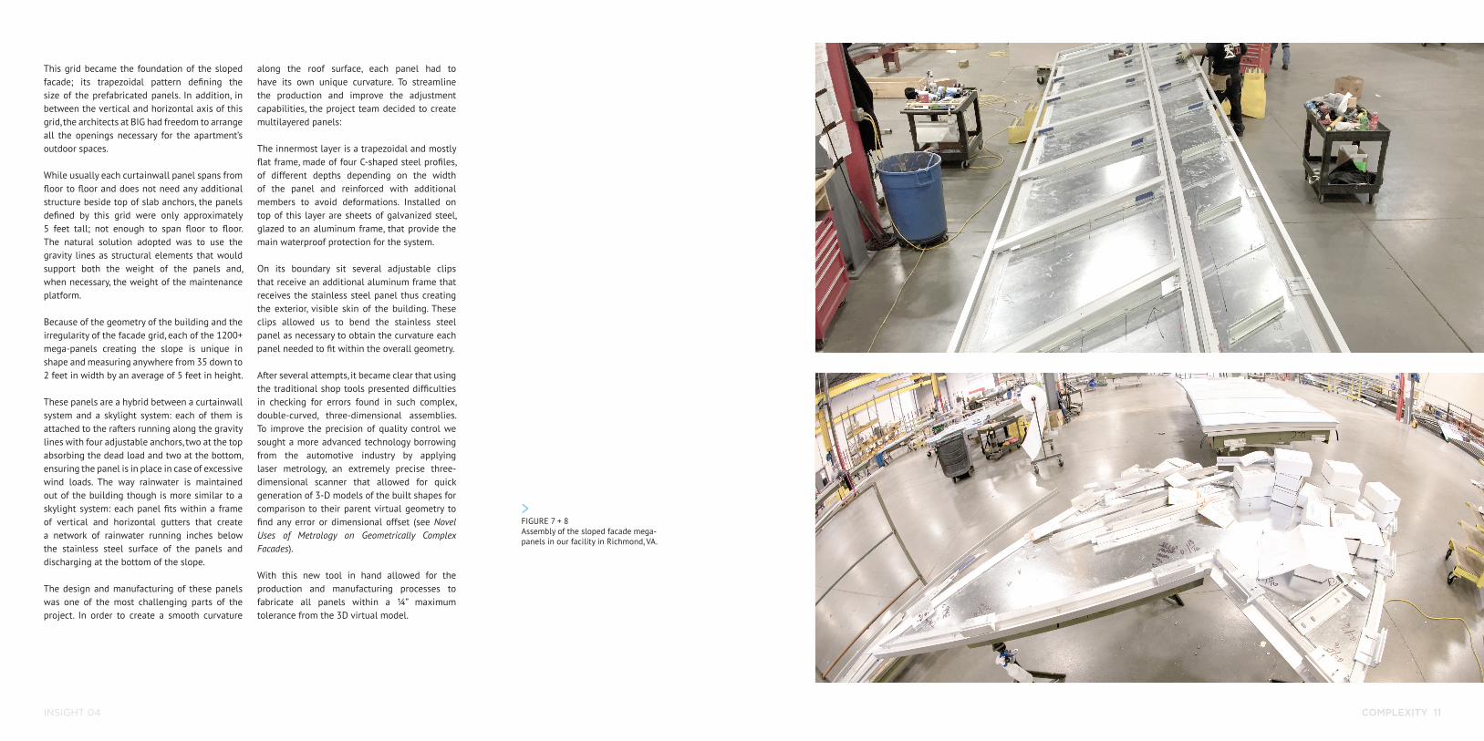
FIGURE 7 + 8Assembly of the sloped facade mega-panels in our facility in Richmond, VA.
INSIGHT 04 COMPLEXITY 13
FIGURE 9Different layers constituting each of the mega-panels: trapezoidal steel frame (bottom), insulated, glazed-in galvanized panels to aluminum frame, offset aluminum frame for rain-screen panel, stainless steel panel (top).
FIGURE 10Geometry deviation measured with laser metrology. Three-dimensional reference points are measured on the build component and overlaid on the original 3D model. The offset of these points from the ideal geometry is automatically calculated: blue is a positive offset, red a negative one. The bigger the cone, the bigger the offset from the original 3D model.
INSIGHT 04 COMPLEXITY 15
FIELD COMPLEXITY
Managing the design and fabrication of such complex parts was an extremely challenging experience for the entire team which continued in the field when the installation of rafters and panels commenced.
Because of its geometry, the slope of the wall changed constantly, ranging from almost completely flat at the lower southwest corner of
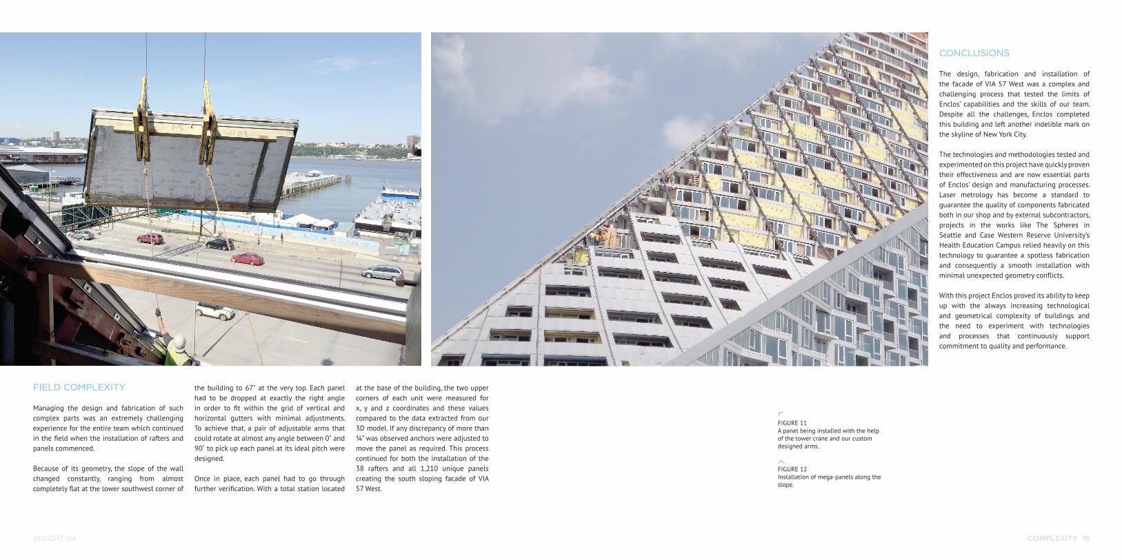
the building to 67˚ at the very top. Each panel had to be dropped at exactly the right angle in order to fit within the grid of vertical and horizontal gutters with minimal adjustments. To achieve that, a pair of adjustable arms that could rotate at almost any angle between 0˚ and 90˚ to pick up each panel at its ideal pitch were designed.
Once in place, each panel had to go through further verification. With a total station located
at the base of the building, the two upper corners of each unit were measured for x, y and z coordinates and these values compared to the data extracted from our 3D model. If any discrepancy of more than ¼” was observed anchors were adjusted to move the panel as required. This process continued for both the installation of the 38 rafters and all 1,210 unique panels creating the south sloping facade of VIA 57 West.
CONCLUSIONS
The design, fabrication and installation of the facade of VIA 57 West was a complex and challenging process that tested the limits of Enclos’ capabilities and the skills of our team. Despite all the challenges, Enclos completed this building and left another indelible mark on the skyline of New York City.
The technologies and methodologies tested and experimented on this project have quickly proven their effectiveness and are now essential parts of Enclos’ design and manufacturing processes. Laser metrology has become a standard to guarantee the quality of components fabricated both in our shop and by external subcontractors, projects in the works like The Spheres in Seattle and Case Western Reserve University’s Health Education Campus relied heavily on this technology to guarantee a spotless fabrication and consequently a smooth installation with minimal unexpected geometry conflicts.
With this project Enclos proved its ability to keep up with the always increasing technological and geometrical complexity of buildings and the need to experiment with technologies and processes that continuously support commitment to quality and performance.
FIGURE 11 A panel being installed with the help of the tower crane and our custom designed arms.
FIGURE 12Installation of mega-panels along the slope.