Building higher with light-weight timber structures – the effect of wind induced vibrations Marie Johansson a , Building technology Andreas Linderholt b , Mechanical Engineering Åsa Bolmsvik c , Building technology Linnaeus University, 351 95 Växjö, Sweden Kirsi Jarnerö d , Jörgen Olsson e SP Sustainable built environment, PG Vejdes väg 15, 351 96 VÄXJÖ, Sweden Thomas Reynolds f University of Cambridge, Department of Architecture, Cambridge CB2 1PX, United Kingdom During the last years the interest in multi-storey timber buildings has increased and several medium-to-high-rise buildings with light-weight timber structure have been designed and built. Examples of such are the 8-storey building Limnologen in Växjö, Sweden, the 9- storey Stadthaus in London, UK and being constructed at the moment, the 14-storey building Treet in Bergen, Norway. These are all light-weight and flexible structures which raise questions regarding the wind induced vibrations. For the building in Norway, the calculated vibration properties of the top floor are on the limit of being acceptable according to the ISO 10137 1 vibration criteria for human comfort. This paper will give a review of building systems for medium-to-high-rise timber buildings. Measured vibration properties for some medium-to-high-rise timber buildings will also be presented. These data have been used for calculating the peak acceleration values for two example buildings for comparison with the ISO standards. An analysis of the acceleration levels for a building with double the height has also been performed showing that designing for wind induced vibrations in higher timber buildings is going to be very important and that more research into this area is needed. 1 INTRODUCTION During the last decades the interest in multi-storey timber buildings has increased. One reason is the change in codes from prescriptive to performance based which has changed among a [email protected]b [email protected]c [email protected]d [email protected]e [email protected]f [email protected]
Transcript
Building higher with light-weight timber structures – the effect of
wind induced vibrations Marie Johanssona, Building technology Andreas Linderholtb, Mechanical Engineering Åsa Bolmsvikc, Building technology Linnaeus University, 351 95 Växjö, Sweden Kirsi Jarneröd, Jörgen Olssone SP Sustainable built environment, PG Vejdes väg 15, 351 96 VÄXJÖ, Sweden Thomas Reynoldsf University of Cambridge, Department of Architecture, Cambridge CB2 1PX, United Kingdom
During the last years the interest in multi-storey timber buildings has increased and several
medium-to-high-rise buildings with light-weight timber structure have been designed and
built. Examples of such are the 8-storey building Limnologen in Växjö, Sweden, the 9-
storey Stadthaus in London, UK and being constructed at the moment, the 14-storey
building Treet in Bergen, Norway. These are all light-weight and flexible structures which
raise questions regarding the wind induced vibrations. For the building in Norway, the
calculated vibration properties of the top floor are on the limit of being acceptable
according to the ISO 101371 vibration criteria for human comfort. This paper will give a
review of building systems for medium-to-high-rise timber buildings. Measured vibration
properties for some medium-to-high-rise timber buildings will also be presented. These
data have been used for calculating the peak acceleration values for two example buildings
for comparison with the ISO standards. An analysis of the acceleration levels for a building
with double the height has also been performed showing that designing for wind induced
vibrations in higher timber buildings is going to be very important and that more research
into this area is needed.
1 INTRODUCTION
During the last decades the interest in multi-storey timber buildings has increased. One reason is the change in codes from prescriptive to performance based which has changed among
other things the requirements for fire safety. An example is the change from prescribing that a building higher than two storeys should be built with incombustible materials to have a requirement that the structural resistance should remain for a certain amount of time during a fire. Another reason is that sustainability has become a major issue in building design and construction within the last decade. One issue is lower energy consumption within the finished building, which to a large part can be achieved by using more energy efficient building services and high performance building envelopes that reduce the heating need for the building. The next issue to tackle is the material and energy use during the construction phase. One way to do this is to change the material used in the structure. It has been calculated that the CO2 emissions could be reduced by around 40% if building with timber instead of concrete2. Both the change in codes and the sustainability issue have given an increase in the use of timber in multi-storey buildings.
The increasing population and ongoing urbanisation are going to increase the need for creating cities with a higher population density. This will lead to an increased need for tall buildings that make the best use of limited space. The environmental potential of high-rise buildings lies in a more efficient use of resources. The interest of land use impact is rising among Life cycle analysis (LCA) practitioners, but there are few studies that address this issue in the building sector3. By adding these elements together the use of tall buildings with timber structure would be an opportunity and provide for ecological, sustainable high and dense developments in urban regions with housing shortage. There are several examples of 8-10 storey buildings with timber as the main structural material, and the first 14-storey building is under construction in Norway during the spring of 2015. Timber has the benefit of having a high strength-to-weight ratio compared to other building materials which in many cases is beneficial, but for the case with medium-to-high-rise buildings this might pose a challenge. The dynamic properties of the building will be quite different from a high-rise building in steel or concrete. This will make it necessary to study the dynamic properties more carefully as horizontal accelerations due to wind load might be an issue already for medium-high buildings in timber.
This paper will give a review of the requirements on vibrations in buildings and address which parameters that are important for design of tall buildings. The important loading regarding global vibrations is the wind load; an overview of the wind loads according to Eurocode 14 will be given. Thereafter, different building systems used for medium-to-high timber buildings will be shown as well as some measured dynamic properties of medium-to-high timber buildings. The last part of the paper will be dedicated to a study of taller (>45 meter) timber buildings and the necessary development of the building systems if these buildings are to be realized.
2 VIBRATIONS IN TALL BUILDINGS
All building systems are designed to withstand both vertical gravity loads and horizontal loads due to wind. The main focus when designing a building has always been the safety aspect calculated based on the maximum loads expected to occur once every 50 years. The interest in the serviceability limit state is attracting more interest in the last decades. It concerns issues such as, acoustic properties, vibration and springiness of floor structures but also acceleration levels due to sway of the complete building. Design guidance which has proved effective for heavy-weight structures may not be suitable for light-weight structures. For example, the requirements for acoustics for a concrete floor structure states that it is enough to include frequencies higher than 100 Hz but that for a light-weight structure, frequencies as low as 20 Hz are important to take into account5.
The comfort performance of a building during wind loading is an important building design issue. The occupants’ perception and tolerance of wind-induced vibration is a subjective assessment and presently there is no single internationally accepted occupant comfort criteria to
set levels for satisfactory vibrations in tall buildings subjected to wind loading. The requirements that are set in the international standards are normally based on acceleration levels where people start to notice and comment on the motion.
There are three different international standards that deal with vibrations in buildings and the human perception of vibrations. There are two older ISO standards, ISO 68976 that cover the range 0.063 Hz to 1Hz and ISO 2631-27 that cover the range 1 Hz to 80 HZ. These two are in agreement with each other and use the Root Mean Square (RMS) value for the acceleration due to a wind velocity with a return period of five years. ISO 101371 covers the range 0.063 Hz to 5 Hz and uses the peak acceleration calculated for a wind velocity with a return period of one year. These two sets of standards will yield slightly different acceptance levels for the same building.
Design methods for along-wind vibration are normally stated in the building codes. In Europe, the relevant code is Eurocode 1, Part 1-44 where the serviceability assessment is made for the maximum along-wind displacement and the characteristic along wind acceleration of the structure. The calculation of acceleration is based on Davenport’s8 representation of the building as a line-like vibrating object. No limit values for criteria are given, only a reference to the material dependent sections of the code. For timber structures, in Eurocode 59, it is in the general requirement stated that it shall be ensured that actions on the structure does not cause unacceptable vibrations with regard to discomfort of occupants. The codes for North America have the same principal background as Eurocode even if some details are different.
There is also an ongoing discussion about the validity of these standards. Kwok et al.10 and Ferrato et al.11 give overviews of vibration acceptability and occupant comfort criteria. The possibility to introduce criteria based on nausea, compensatory behavior and task performance reduction instead of complaints is discussed in Lamb et al.12 and in Ferrerato et al.11 it is argued to make it possible to obtain less conservative structural designs of tall buildings.
3 DYNAMIC MODEL
If the building is considered as a line-like vibrating object, then its structure may be represented as a vertical cantilever, fixed at the foundation and free at the top. The global dynamics of a multi-story building can then, in a simplified manner, be analyzed by approximating the building to be a uniform cantilever beam. According to the well-known Euler-Bernoulli beam theory, the homogeneous part of the governing equation of motion is
𝐸𝐸 ∙ 𝑑4𝑤𝑑𝑧4 + 𝜌𝜌 ∙ 𝑑
2𝑤𝑑𝑡2 = 0 ( 1 )
in which 𝜌, 𝜌 and 𝐸𝐸 constitute the density, cross sectional area and bending stiffness respectively. The general solution to this equation is
which is valid for 0 ≤ 𝑧 ≤ ℎ. Assuming that only the first bending mode contributes to the displacement and making the substitute
𝑤(𝑧, 𝑡) = 𝜓(𝑧) ∙ 𝜂(𝑡) ( 6 )
the modal mass (𝑚� ), modal stiffness (𝑘�) and modal load 𝑝� can be calculated as:
𝑚� = 𝜌𝜌� 𝜓(𝑧)ℎ
0∙ 𝜓(𝑧)𝑑𝑧 ( 7 )
𝑘� = 𝐸𝐸 � 𝜓′′(𝑧)ℎ
0∙ 𝜓′′(𝑧)𝑑𝑧 ( 8 )
𝑝� = � 𝑃(𝑧)ℎ
0∙ 𝜓(𝑧)𝑑𝑧 ( 9 )
In which 𝑃(𝑧) is the distributed wind load. The continuous problem has then been re-placed with a discrete single-degree-of-freedom system, depicted in Fig. 1.
𝑚��̈�(𝑡) + 𝑘�𝜂(𝑡) = 𝑝�(𝑡) ( 10 )
When damping is added the governing equation of motion becomes
𝑚��̈�(𝑡) + �̃��̇�(𝑡) + 𝑘�𝜂(𝑡) = 𝑝�(𝑡) ( 11 )
in which �̃� is the modal damping. In the codes used for calculation of responses due to wind loads, simplified expressions for the mode shapes are often used.
Fig. 1 – A single-degree-of-freedom system representing the building when one assumed mode is used.
4 ACCELERATIONS AND WIND LOADS ACCORDING TO EUROCODE
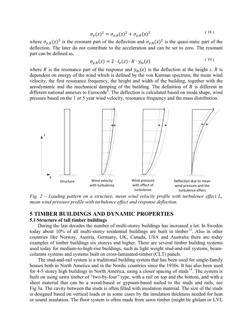
Wind loads vary greatly in speed, force and direction over time. To simplify this in codes, the wind is seen as a quasi-static load for buildings with high stiffness and damping. For high slender structures also the gust effect is included as a turbulence factor added to the quasi-static wind load. The effect of the wind on a single building will be affected by the terrain around it as well as the shape and height of the building.
In Europe wind loads are defined in Eurocode 1, Part 1-44. There the fundamental basic wind velocity 𝑣𝑏 is defined by the 10-minute mean wind speed at a height of 10 meter above ground that is exceeded once every 50 year. This basic wind velocity is normally based on measurements by the national weather service and can be found in tables for different locations. The wind velocity for shorter times (in this case 5 years) can then be calculated,
𝑣𝑏5 = 𝑣𝑏 ∙ 0.75 ∙ �1 − 0.2 ∙ 𝑙𝑙 �−𝑙𝑙 �15�� ( 12 )
The one year wind velocity can then be calculated as 0.72 times the five year wind speed. The wind velocity in the vicinity of a structure is dependent on the local terrain around the structure and is varying with height (z) above ground, see Fig 2. According to Eurocode 14 mean wind velocity next to a structure can be expressed as,
The first term 𝑐𝑜 is an orography factor (set to 1.0 in normal cases) and 𝑘𝑟 is a terrain roughness factor. The terrain roughness factor is based on 5 different terrain categories taking the surrounding terrain into account, varying from close to the sea to inside a city with high surrounding buildings. The term 𝑧0 is the roughness length that varies between terrains; the term 𝑧0,𝐼𝐼 is a reference terrain roughness length. The mean wind pressure can then be calculated using
𝑞𝑚(𝑧) = 12 ∙ 𝜌 ∙ 𝑣𝑚(𝑧)2 ( 14 )
where ρ is the air density (normally set to 1.25 kg/m3). For high and flexible buildings it is, however, necessary to take also the dynamic effects of
the wind load into account. This is done by including a turbulence intensity factor Iv(z), defined as the standard deviation of the turbulence divided by the mean velocity, see Fig 2, as,
𝐸𝑣(𝑧) = 𝜎𝑣𝑣𝑚(𝑧) ( 15 )
where 𝜎𝑣 is the standard deviation of the turbulence and 𝑣𝑚(𝑧) is the mean wind velocity. The standard deviation of the turbulence is calculated as the basic wind velocity times the
terrain roughness factor 𝑘𝑟. The response of the structure due to the turbulence intensity can be divided into two parts; the background response (B) and the resonance response (R). The background response is due to the quasi-static part of the wind load while the resonance response is due to the dynamic properties of the building and the dynamic part of the wind load.
The horizontal peak acceleration of the structure ÿ(𝑧) can be written as,
ÿ(𝑧) = 𝑘𝑝 ∙ 𝜎ÿ(𝑧) ( 16 )
where 𝑘𝑝 is a peak factor that relates the mean and the deviation of the response and 𝜎ÿ(𝑧) is the standard deviation of the acceleration (Root mean square value, RMS) defined as,
𝜎ÿ(𝑧) = (2𝜋𝑓1)2 ∙ 𝜎𝑦(𝑧) ( 17 )
where 𝑓1is the first bending resonance frequency of the building and 𝜎𝑦(𝑧) is the standard deviation of the deflection. The standard deflection is dependent on both the quasi-static and the resonant part of the deflection response and can be defined as
𝜎𝑦(𝑧)2 = 𝜎𝑦,𝑅(𝑧)2 + 𝜎𝑦,𝐵(𝑧)2 ( 18 )
where 𝜎𝑦,𝑅(𝑧)2 is the resonant part of the deflection and 𝜎𝑦,𝐵(𝑧)2 is the quasi-static part of the deflection. The later do not contribute to the acceleration and can be set to zero. The resonant part can be defined as, 𝜎𝑦,𝑅(𝑧) = 2 ∙ 𝐸𝑣(𝑧) ∙ 𝑅 ∙ 𝑦𝑚(𝑧) ( 19 )
where 𝑅 is the resonance part of the response and 𝑦𝑚(𝑧) is the deflection at the height z. 𝑅 is dependent on energy of the wind which is defined by the von Karman spectrum, the mean wind velocity, the first resonance frequency, the height and width of the building, together with the aerodynamic and the mechanical damping of the building. The definition of 𝑅 is different in different national annexes to Eurocode4. The deflection is calculated based on mode shape, wind pressure based on the 1 or 5 year wind velocity, resonance frequency and the mass distribution.
Fig. 2 – Loading pattern on a structure, mean wind velocity profile with turbulence effect Iv, mean wind pressure profile with turbulence effect and response deflection.
5 TIMBER BUILDINGS AND DYNAMIC PROPERTIES
5.1 Structure of tall timber buildings
During the last decades the number of multi-storey buildings has increased a lot. In Sweden today about 10% of all multi-storey residential buildings are built in timber13. Also in other countries like Norway, Austria, Germany, UK, Canada, USA and Australia there are today examples of timber buildings six storeys and higher. There are several timber building systems used today for medium-to-high-rise buildings, such as light weight stud-and-rail systems, beam-columns systems and systems built on cross-laminated-timber (CLT) panels.
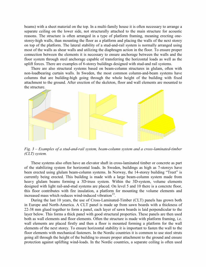
The stud-and-rail system is a traditional building system that has been used for single-family houses both in North America and in the Nordic countries since the 1930s. It has also been used for 4-5 storey high buildings in North America, using a closer spacing of studs14. The system is built on using sawn timber of “two-by-four” type, with a rail on top and the bottom, and with a sheet material that can be a wood-based or gypsum-based nailed to the studs and rails, see Fig 3a. The cavity between the studs is often filled with insulation material. The size of the studs is designed based on vertical loads or in some cases by the insulation thickness needed for heat or sound insulation. The floor system is often made from sawn timber (might be glulam or LVL
Structure Wind velocity with turbulence
Wind pressure with effect of
turbulence
Deflection due to mean wind pressure and the
turbulence effect
y
z
beams) with a sheet material on the top. In a multi-family house it is often necessary to arrange a separate ceiling on the lower side, not structurally attached to the main structure for acoustic reasons. The structure is often arranged in a type of platform framing, meaning erecting one-storey-high walls, than mounting the floor as a platform and placing the walls of the next storey on top of the platform. The lateral stability of a stud-and-rail system is normally arranged using most of the walls as shear walls and utilizing the diaphragm action in the floor. To ensure proper connection between the elements it is necessary to ensure anchorage between the walls and the floor system through steel anchorage capable of transferring the horizontal loads as well as the uplift forces. There are examples of 6-storey buildings designed with stud-and rail systems.
There are also structural systems based on beam-column structures in glulam, often with non-loadbearing curtain walls. In Sweden, the most common column-and-beam systems have columns that are building-high going through the whole height of the building with fixed attachment to the ground. After erection of the skeleton, floor and wall elements are mounted to the structure.
Fig. 3 – Examples of a stud-and-rail system, beam-column system and a cross-laminated-timber (CLT) system.
These systems also often have an elevator shaft in cross-laminated timber or concrete as part of the stabilizing system for horizontal loads. In Sweden, buildings as high as 7-storeys have been erected using glulam beam-column systems. In Norway, the 14-storey building “Treet” is currently being erected. This building is made with a large beam-column system made from heavy glulam beams forming a 3D-truss system. Within the 3D-system, volume elements designed with light rail-and-stud systems are placed. On level 5 and 10 there is a concrete floor, this floor contributes with fire insulation, a platform for mounting the volume elements and increased mass which reduces wind-induced vibration15.
During the last 10 years, the use of Cross-Laminated-Timber (CLT) panels has grown both in Europe and North-America. A CLT panel is made up from sawn boards with a thickness of 22-38 mm glued together to form a panel, each layer of sawn boards is laid perpendicular to the layer below. This forms a thick panel with good structural properties. These panels are then used both as wall elements and floor elements. Often the structure is made with platform framing, i.e. wall elements are placed firstly and then a floor is mounted forming a platform for the wall elements of the next storey. To ensure horizontal stability it is important to fasten the wall to the floor elements with mechanical fasteners. In the Nordic countries it is common to use steel struts going all through the height of the building to ensure proper attachment to the ground and ensure protection against uplifting wind-loads. In the Nordic countries, a separate ceiling is often used
to ensure proper vertical sound insulation between apartments. In central Europe, it is common to use a 5-10 cm thick layer of concrete on top of the floor elements to ensure sound insulation. There are examples of 8-10 storey buildings built with CLT-systems in Sweden, UK and Australia.
5.2 Dynamic properties of some medium-rise timber buildings
The dynamic properties and acceleration levels of timber buildings have usually not been in focus as the buildings have been classified as low-to-medium high buildings. There are therefore very limited amount of data regarding dynamic properties of timber buildings. There are, however, some studies conducted. In these studies, most often accelerometers are used to measure the acceleration at several points and in several directions on the top of the buildings. In some cases also the wind speed is measured with an anemometer. The measurement data are later used in Operational Modal Analysis (OMA) to get the mode shapes, natural frequencies and damping ratios. Table 1 includes properties for several buildings found in the literature.
Table 1 – Building system, building height, mass, first resonance frequency (bending) and damping ratio of some timber buildings found in the literature. Building system Height
[m] Mass
[kg/m3] Frequency
[Hz] Damping ratio [%]
Source
Light frame systemi 19.5 18 2.5 3.1 Ellis and Bougard 200116 Light frame system 19.5 67 3.6 2.8 Ellis and Bougard 200116 CLT + stud and rail 25.0 46 2.3 2.3 Reynolds et al. 201417 CLT + concrete topping 21.0 150 2.1 5.2 Reynolds et al. 201518 CLT 27.0 2.3 1.9 Reynolds et al. 201417 Glulam post and beami
with concrete shafts 22.1 2.7 1.2 Hu et al. 201419
Glulam post and beam with concrete shafts
22.1 ~60 2.8 3.8 Hu et al. 201419
Glulam post and beam 18.3 2.8 1.4 Hu et al. 201419 Mixed glulam post and beam frame with concrete framei
21.8 2.1 1.5 Hu et al. 201419
CLT platform mixed with post and beami
12.6 3.2 1.3 Hu et al. 201419
Glulam trussii 43.2 0.9 2.0 Bjertnes and Malo 201420 i Building without finishing and partitions ii Estimated value used in design
From the data given in the references it can be seen that there is a huge difference in the mass of the structures calculated based on the amount of material in the buildings. The first two rows represent the same building before and after the interior walls and the outer brickwork was assembled. There is also a great difference in mass depending on if a concrete topping is used on the floors or not. For high-rise steel and concrete buildings the first resonance frequency is approximatively set to 46/h in Eurocode 1, (Annex F) 4 where h is the height of the building.
For these buildings the value varies between 40/h and 70/h which shows that this simple rule should be used with care. Eurocode 1, (Annex F)4 gives damping ratios for buildings in reinforced concrete and buildings with steel structures. For the fundamental mode of vibration of buildings with reinforced concrete, Eurocode4 suggests an equivalent viscous damping ratio of
1.6%, and for steel structures it suggests 0.8% (these values have been calculated from the logarithmic decrement of structural damping given in the code). There is no recommendation for timber buildings in Eurocode4. The former Swedish standard21 (BSV97) suggests a damping ratio of 1.4%. Based on the measurements in Table 1 the damping ratio in the old Swedish code is on the conservative side and a higher value could be used.
6 APPLICATION EUROCODE ON SOME EXSITING AND FUTURE
TIMBER BUILDINGS
6.1 Acceleration levels for some buildings
The acceleration levels at the top of some buildings according to Eurocode 1 and ISO standards can be calculated if the dimensions and mass as well as the first resonance and damping ratio of the buildings are known. For two of the buildings above, these data are known and the acceleration levels are calculated according to the codes and compared with the limits in the ISO standards. To compare the buildings they are placed in the same place with the same terrain data, meaning a fundamental basic wind velocity of 𝑣𝑏 = 24𝑚/𝑠 and a terrain with small hinders. To compare the values the calculations are performed according to ISO 101371 based on the peak acceleration with a wind velocity with a return period of 1 year and according to ISO 6897 based on the standard deviation (RMS) value of the acceleration for a wind velocity with a return period of 5 years. This will mean a wind velocity of 17.1 m/s with a return period of 5 years and velocity of 12.3 m/s for a return period of 1 year. The data for the mass includes 30% of the imposed load of 2 kN/m2 of floor area as prescribed in Eurocode22.
Table 2 – Input data for the calculation of acceleration levels for two example buildings. Building 1 Building 2 Building system CLT+stud and rail system Glulam beam-column with
concrete elevator shafts Height 24.0 m 22.1 m Width 40.2 m ~58 m Mass per unit height 31 000 kg/m 52 000 kg/m First resonance frequency 2.3 Hz 2.8 Hz Damping ratio 2.3 % 3.8% RMS value 0.025 m/s2 0.019 m/s2 Peak acceleration 0.034 m/s2 0.013 m/s2
If the values are used following the ISO 101371 diagram it is possible to see that the peak acceleration values are below the limit for the comfort level, see Fig 4. Building 1, is higher, has less damping and lower mass than building 2 which results in higher acceleration levels.
Fig. 4 – The peak acceleration levels for the two example buildings in the diagram for comfort according to ISO 101371. 5.2 Model of 16 stories, 48 meter high building
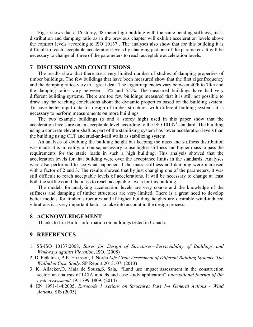
The interest in building higher in timber has increased during the last years. It is therefore interesting to see how the building systems need to be changed to have acceptable acceleration levels at the highest floors. There are according to chapter 3 basically three parameters that can be varied to change the acceleration levels, the bending stiffness, the damping ratio and the mass of the building. An analysis was made to see how the acceleration levels for a building with the same bending stiffness, mass distribution and damping as building 1, was to be designed with a building height of 48 m, corresponding to 16 stories. To actually design this building, of course, both higher stiffness and higher mass would be necessary to take the vertical and horizontal static load. Analyses were also performed by increasing the bending stiffness by 2 and 3; the same was done for the mass and the damping ratio to see the effect on the acceleration levels.
Fig. 5 – Peak acceleration levels according to ISO 101371 for a 48 meter high building (Diamond - Basic case) and the effect of doubling and tripling the mass (triangles), stiffness (squares) and damping ratio (circles).
Fig 5 shows that a 16 storey, 48 meter high building with the same bending stiffness, mass distribution and damping ratio as in the previous chapter will exhibit acceleration levels above the comfort levels according to ISO 101371. The analyses also show that for this building it is difficult to reach acceptable acceleration levels by changing just one of the parameters. It will be necessary to change all three of the parameters to reach acceptable acceleration levels.
7 DISCUSSION AND CONCLUSIONS
The results show that there are a very limited number of studies of damping properties of timber buildings. The few buildings that have been measured show that the first eigenfrequency and the damping ratios vary to a great deal. The eigenfrequencies vary between 40/h to 70/h and the damping ratios vary between 1.3% and 5.2%. The measured buildings have had very different building systems. There are too few buildings measured that it is still not possible to draw any far reaching conclusions about the dynamic properties based on the building system. To have better input data for design of timber structures with different building systems it is necessary to perform measurements on more buildings.
The two example buildings (6 and 8 storey high) used in this paper show that the acceleration levels are on an acceptable level according to the ISO 101371 standard. The building using a concrete elevator shaft as part of the stabilizing system has lower acceleration levels than the building using CLT and stud-and-rail walls as stabilizing system.
An analysis of doubling the building height but keeping the mass and stiffness distribution was made. It is in reality, of course, necessary to use higher stiffness and higher mass to pass the requirements for the static loads in such a high building. This analysis showed that the acceleration levels for that building were over the acceptance limits in the standards. Analyses were also performed to see what happened if the mass, stiffness and damping were increased with a factor of 2 and 3. The results showed that by just changing one of the parameters, it was still difficult to reach acceptable levels of accelerations. It will be necessary to change at least both the stiffness and the mass to reach acceptable levels for this building.
The models for analyzing acceleration levels are very coarse and the knowledge of the stiffness and damping of timber structures are very limited. There is a great need to develop better models for timber structures and if higher building heights are desirable wind-induced vibrations is a very important factor to take into account in the design process.
8 ACKNOWLEDGEMENT
Thanks to Lin Hu for information on buildings tested in Canada.
9 REFERENCES
1. SS-ISO 10137:2008, Bases for Design of Structures—Serviceability of Buildings and
Walkways against Vibration, ISO. (2008) 2. D. Peñaloza, P-E. Eriksson, J. Norén.Life Cycle Assessment of Different Building Systems: The
Wälluden Case Study. SP Report 2013: 07, (2013) 3. K. Allacker,D. Maia de Souza,S. Sala,. “Land use impact assessment in the construction
sector: an analysis of LCIA models and case study application” International journal of life cycle assessment 19: 1799-1809. (2014)
4. EN 1991-1-4:2005, Eurocode 1 Actions on Structures Part 1-4 General Actions - Wind Actions, SIS (2005)
5. J. Forssén, W. Kropp, J. Brunskog, S. Ljunggren, D. Bard, G. Sandberg, F. Ljunggren, A.
Ågren, O. Hallström, H. Dybro, K. Larsson, K. Tillberg, K. Jarnerö, L-G. Sjökvist, B. Östman, K. Hagberg, Å. Bolmsvik, A. Olsson, C-G. Ekstrand, M. Johansson, Acoustics in wooden buildings –State of the art 2008, Vinnova project 2007-01653, SP Rapport 2008:16, (2008)
6. SS ISO 6897: 1984, Guidelines for the Evaluation of the Response of Occupants of Fixed Structures, Especially Buildings and Offshore Structures, to Low-Frequency Horizontal Motion (0.063 to 1.0 Hz), ISO, (1984)
7. SS ISO 2631-2:2003, Mechanical vibration and shock – Evaluation of human exposure to whole-body vibration – Part 2: Vibration in buildings (1 Hz to 80 Hz), SIS (2003)
8. A.G. Davenport, Response of slender, line-like structures to gusty wind. Proceedings of the Institution of Civil Engineers 23(3), pp.389–408 (1962)
9. SS EN 1995-1-1:2004 Eurocode 5: Design of timber structures. General − Common rules and rules for buildings; (2004)
10. K.C.S. Kwok, P. A. Hitchcock, M.D. Burton. "Perception of vibration and occupant comfort in wind-excited tall buildings." Journal of Wind Engineering and Industrial Aerodynamics 97(7-8): pp. 368-380. (2009)
11. J.A. Ferrareto, E.N.C. Mazzilli, F.L.S. Ricardo. "Wind-induced motion on tall buildings: A comfort criteria overview." Journal of Wind Engineering and Industrial Aerodynamics 142: 26-42 (2015)
12. S. Lamb, K. C. S. Kwok, D. Walton. "Occupant comfort in wind-excited tall buildings: Motion sickness, compensatory behaviours and complaint." Journal of Wind Engineering and Industrial Aerodynamics, 119: 1-12 (2013)
13. http://www.tmf.se/statistik/traandel-flerfamiljsbostader (2015) 14. P-E. Eriksson, 2-tum-4: ryggraden i amerikanska flerbostadshus (2 by 4s: the backbone of
american multi-storey buildings, in Swedish). Utlandsrapport från Sveriges tekniska attachéer. USA, 1100-2999 ; (1993)
15. R.B. Abrahamsen, K.A. Malo, : “Structural design and assembly of “Treet” – a 14-storey timber residential building in Norway”. In: World Conference on Timber Engineering, Quebec City (2014)
16. B.R. Ellis,A.J. Bougard, “Dynamic tresting and stiffness evaluation of a six-storey timber framed building during construction”. Engineering Structures 2(10) pp. 1232-1242. (2001)
17. T. Reynolds, Å. Bolmsvik, J. Vessby, W-E. Chang, R.Harris, J. Bawcomber, J. Bregulla, “Ambient vibration testing and modal analysis of multi-storey cross-laminated timber buildings”. In: World Conference on Timber Engineering, Quebec City (2014)
18. T. Reynolds, R. Harris, W-S. Chang, J. Bregulla, J.Bawcombe. Ambient vibration tests of a cross-laminated timber building. Proceedings of the ICE - Construction Materials, pp.1–11. (2015)
19. L. Hu, A. Omeranovic, S. Gagnon, S.M. Mohammad, “Wind-induced vibrations of tall wood buildings – is it an issue?” In: World Conference on Timber Engineering, Quebec City (2014)
20. M.A. Bjertnes, K.A. Malo, “Wind.-induced motions of “Treet” – a 14-storey timber residential building in Norway”. In: World Conference on Timber Engineering, Quebec City (2014)
21. Boverket, Boverkets handbok om snö- och vindlast: BSV 97, (Hand book on snow- and wind loads: BSV97, in Swedish), Boverket, Karlskrona, (1997)
22. SS EN 1990:2002 Eurocode – Basis of structural design, SIS (2002)