The author hereby grants to MIT permission to reproduce and to distribute publicly paper and electronic copies of this thesis document in whole or in part in any medium now known or
hereafter created.
Student Signature: _______________________________________________________________ Department of Architecture
William J. Mitchell Professor of Architecture and Media Arts and Sciences
Thesis Reader
2
Building Information: Means and methods of communication in design and construction.
by
Joshua M. Lobel
Submitted to the Department Of Architecture on May 23, 2008 in Partial Fulfillment of the Requirements for the Degree of Masters Of Science In Architecture Studies.
Abstract Architects are trained and practiced in the means and methods of design. These are distinct from the physical means and methods of construction, which have traditionally been in the hands of contractors. The successful realization of construction does not necessitate or rely on a direct link between the processes of design and construction. However, the constructability of a design is dependent on an effective means of communicating between the two. This thesis illustrates that the perceived complexity of constructability is often predicated on the efficacy of communication between the designer and the contractor. I present three models of communication: a linear transmissive model similar to that of Shannon and Weaver, a “speech-circuit” model based on that of Saussure, and a semiotic-constructionist model derived from Peirce and Papert. Through interviews, observations, and experiments with practicing architects and architecture students, I investigate the implications of these models on the perceived and contractual roles and responsibilities of architects and contractors. My findings suggest that in design, communication is also an act of design and construction. Best illustrated by the constructionist model of communication, acts of making and re-making are fundamental to the way that architects and contractors relate to design information. The automation of these acts through emerging technologies - such as BIM - lead to increased reliance on fixed data constructs in lieu of dynamic, individual interpretations of information. This can result in the loss of expert knowledge which does not fit a standardized model, and the dis-integration of meaningful communication between design and construction information.
Thesis Advisor: George Stiny Professor of Design and Computation
3
4
Contents
Abstract
1. Introduction 9
2. Models of Communication 17
3. Roles and Responsibilities :: Means and Methods 23
4. Shape Experiments 27
5. Case Studies 35
6. Computer Aids to Design 45
7. Conclusion 65
Illustration Credits 71
Bibliography 73
Appendix 77
5
6
Acknowledgements
I would like to thank the faculty of the Computation Group and my fellow
students for the wonderful opportunity I have had over the past two years
to work and study with you. A special thanks to Professor George Stiny.
Thank you to Yanni Loukissas, my friend and colleague for more than a
decade now, whose insight and ideas continue to inspire and challenge.
Thank you to my family.
And thank you to Kate, whom I will soon marry. Without you I never
would have made it in the front door…or back out.
7
8
1. Introduction
“First, the taking in of scattered particulars under one Idea, so that
everyone understands what is being talked about…”
- Plato, Phaedrus, 265D
Architects are trained and practiced in the means and methods of design.
These are distinct from the physical means and methods of construction,
which are typically in the hands of contractors. The successful realization
of construction does not depend on a direct correlation between the
process of design and the process of construction. However, the
constructability of a design is predicated on an effective means of
communicating between the two.
Increased demands have been placed on the Architectural, Engineering,
and Construction (AEC) industry to design and build projects that
consume fewer material and economic resources, conform to tighter
construction tolerances, display greater formal complexity, remain
operable for longer time periods at lower costs, and have a smaller overall
environmental impact. Similar demands and advances in other industries,
such as the automotive and marine industries, have been cited as
successful examples upon which the AEC industry should be remodeled1.
Much of this remodeling effort focuses on the adoption of the
technological means and methods of these industries. In particular, the
AEC industry has subsumed the particular use of computer aids to design
and manufacture from these industries as a generic approach to designing
and making. Proponents at the forefront of this movement claim that
1 See Kieran, Stephen, and Timberlake, James. (2003). Refabricating Architectre: How
Manufacturing Methodologies are Poised to Transform Building Construction. (McGraw Hill Professional).
9
digital technology can provide the means and methods for translating
design into building information2. Currently, the favored method for
achieving this is by explicitly associating textual and mathematical
information to digital geometry through parametric3 software and
relational databases. These methods are adopted directly from the
automotive, marine, and manufacturing industries. By superficially
adopting the means and methods of other industries, architects also adopt
their embedded terminology and metaphors. These metaphors shape not
only how computer aids to design are developed, but also our mental
models of their purpose and usefulness. A problem occurs when these
metaphors become so commonplace that they go unchallenged. An
excellent example comes from the design of the operating system for the
One Laptop Per Child (OLPC) project. Recognizing the implications that
familiar desktop metaphors have upon what and how children learn, the
OLPC team designed their interface using the metaphor of a
‘neighborhood’. The change of metaphor in this case was not just
symbolic, but a powerful method for opening up entirely new ways of
thinking about how a computer designed for children should function.
Commenting on this approach Nicholas Negroponte, the creator of the
OLPC project and an early pioneer in computer aided design in
architecture, stated “…one of the saddest but most common conditions in
elementary school computer labs…is the children are being trained to use
Word, Excel and PowerPoint…I consider that criminal, because children
should be making things, communicating, exploring, sharing, not running
2 See Shelden, Dennis. (2006) “Tectonics, Economics and the Reconfiguration of Practice:
The Case for Process Change by Digital Means” in Architectural Design, v76-4, July/August: p82-87.
3 The use of the term parametric with respect to digital design software is a poorly understood term and is regularly conflated with history-based software. The details of this will be discussed in Chapter 6.
10
office automation tools.”4 Should the development of computer aids for
design be any different?
There is an implicit assumption in the use and development of
contemporary Computer Aided Design (CAD) technology that being able
to generate, and having access to, more information will increase the
ability of designers and contractors to manage increasingly complex
projects. At the same time, this also demands increased attention to the
management of such substantial amounts of information. In Getting
complexity organized: Using self-organisation in architectural
construction, Fabian Sheurer of the architectural consulting firm
DesigntoProduction states, "…when it comes to actual construction of a
complex building, the question arises: What is a reasonable quantity of
explicit information for a specific design, and how does one communicate
it in a reasonable fashion?"[17 p79]
This thesis shows that in architecture the perceived complexity of a design
is a measure of the difficulty that a particular project team (architect,
contractor, and consultants) has in translating the design information into
construction information. Every design-construction problem can be
represented in multiple ways.[18] The clarity and comprehensibility of
intention and meaning in the representation of design and construction
information is a function of human perception. Because any medium of
human communication is open to interpretation, the amount of ambiguity
in any representation is always greater than zero. The constructability of a
project is therefore predicated on the efficacy of communication between
design and construction information. The feasibility of a project may be in
doubt as a result of mismatched interpretations of information. Interpreting
design information as a discrete set of physical elements and fabrication /
assembly procedures is not an easy or reliable process. I present three
models of communication: a linear transmissive model similar to that of
Shannon and Weaver, a “speech-circuit” model based on that of Saussure,
and a semiotic-constructionist model derived from Peirce and Papert.
Through interviews, observations, and experiments with practicing
architects and architecture students, I investigate the relevance and
implications of these models on the development of computer aids to
design.
Design is an act of seeing, thinking, and making. It is a construct involving
the use of the eye, the mind, and the hand. Beginning in the 1960’s digital
computer technology was developed to aid architectural design under the
auspices of “a man-machine graphical communication system”.[25] Given
the underlying bit-wise structure of digital technology, the majority of
computational tools employed in architecture since then have been
variations of canonical production systems5. The evolution of
computational tools has also tended to conform to advances in technology,
leaving the responsibility of determining their usefulness to designers6. In
the 1970’s George Stiny and James Gips introduced an algebra for visual
calculating known as Shape Grammars.[21][22][23] Fundamental to the
algebra behind Shape Grammars is the use of visual perception in design
5 “A production says how, from one statement, string, or “enunciation”, of such and such a
form, one may derive another string of specified form. A canonical system, which is a set of such productions and some initially given statements, does not even describe a process; instead it specifies the extent of a set of strings by (recursively) specifying how to find things in that set.” [13 p220]
6 Such tools include: Lindenmayer systems (L-systems), genetic algorithms, and cellular automata.
12
and computation. The development of shape grammars differed
significantly from other computational systems because it did not rely on a
predetermined or fixed set of elements. While most computational systems
were (and are) aimed at explaining and eradicating ambiguity, Shape
Grammars embraced it as an inherent and necessary aspect of any design
process.[2, footnote 8 to Chapter 9][19][24] The field of Shape Grammars
and my work with George Stiny over the past two years has played a
major role in my research, and provided a touchstone by which my work
was guided.
Methods. The problem of communication in design and construction will
be presented through both theoretical and empirical investigations. The
theoretical investigations are presented within the framework of various
models of communication. These models include the mathematical theory
model of Claude Shannon and William Weaver, the speech-circuit model
of Ferdinand de Saussure, and a semiotic-constructionist model based on
the work of C.S. Peirce and Seymour Papert. The empirical investigation
begins with an analysis of the contractual obligations of architects and
contractors with respect to the production of documentation, as stipulated
by the American Institute of Architects (AIA).
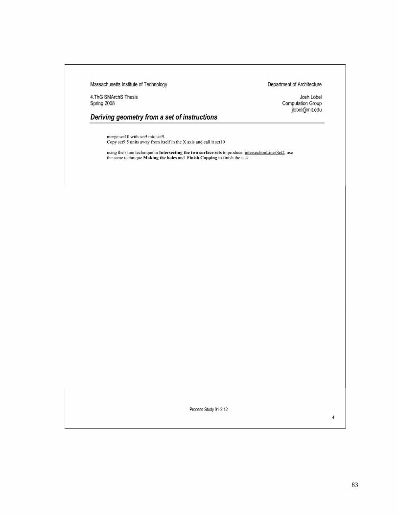
Next, the results of a series of experiments into design communication are
presented. The subjects for these experiments were several graduate
students in the Department of Architecture at the Massachusetts Institute
of Technology (MIT) and practicing architects in the United States. To
study the difficulty of communicating geometric design information,
individuals were asked to translate a set of dimensioned drawings of a
single shape into a set of written instructions. Those written instructions
13
were then given to other individuals with which to re-derive the shape7.
Full documentation of the experiments and results are provided in the
Appendix.
Following the shape experiments, notes from a series of case studies
conducted with individuals at several architecture firms is presented and
discussed. The goal of these case studies was to determine how design
information is communicated in practice along with how, why, and what
computer aids are currently being employed. I followed an ‘unstructured
interview’ methodology in order to encourage the individual expression of
interviewee’s ideas. The interviews were conducted with one individual
from each of the following firms: Foster + Partners, London office,
individual with the Specialist Modeling Group; SHoP Architects PC, New
York City; and SOM (Skidmore, Owings & Merrill LLP), New York City,
individual with the Computational Design Group.
The next section begins with a distinction between the act of design and
the result of design. The verb design implies certain associative leaps and
intuitive calculations that are made based on seeing and thinking and
doing.[24][18] The noun design indicates the outcome of a process that
can be analytically rationalized into a series of discrete procedures. In the
Architecture, Engineering, and Construction (AEC) industry digital
technology is employed in the service of both the process and product of
design. There may or may not be a direct link between the design process
and the construction product. I provide an overview of the general data
7 The geometry of the shape was developed based on a similar example created by Paul Hamilton which he reported on in his article, “A Primer on MCAD Modeling Technology, Part 2: Design Intent is Not Necessarily in the Eye of the Beholder.” CADCAMNet, July 26, 2007. (Ash Bridge Media LLC). Available online at http://www.newslettersonline.com/user/user.fas/s=63/fp=3/tp=47?T=open_article,959682&P=article (last accessed May 5, 2008).
structures upon which most CAD systems are developed to better
understand how these systems influence acts of communication in design
and construction. I then discuss the advent of Building Information
Modeling (BIM) within the context of interoperability, and compare it to
Michael Reddy’s Toolmakers Paradigm fable of communication. By
juxtaposing statements made regarding the potential of computers to aid in
design from the 1975 and 2007, I argue that the development of design
technology has been stifled. I propose that the problems are to be found in
our mental models, not our digital models. My contribution is the
development of criteria with which to determine the usefulness of
computer aids to design. These criteria are the degree to which design
technology facilitates wasteful versus productive acts of repetition in
design.
In conclusion, I provide a critique of the current standards-based
approaches to design communication which rely on the disambiguation of
information through a fixed data model. The danger of using such models
is that expert knowledge which is not accounted for in the standards could
be lost. Furthermore, a rigid and inflexible vocabulary could lead to the
dis-integration of meaningful communication between design and
construction information. I discuss several reasons for why these
approaches continue to fail. First, they have in the past. Second, they are
built on the assumption that meaning can unambiguously be connected
with symbolic information. Third, these models assume and that
individual interpretation is not necessary in the communication of design
and construction. And lastly, these approaches assume that the solution
must come from the formulation of a new model, rather than a new
mindset.
15
16
2. Models of Communication
In the 1940’s Claude Shannon and Warren Weaver developed a linear
transmission model of communication while working at Bell Telephone
Labs. They were most concerned with maximizing the speed, efficiency,
and clarity of information transmitted over telephone lines and radio
waves. The success of their model was measured in “bits per second”.[20]
Their model reduced the problem of communication to the technical issues
involved with the transmission of information across a physical medium.
This model proved valuable for such research and became the basis for
their “mathematical theory of communication”. [20] This model was
quickly adopted as the basis for more generic models of communication
other than those of a purely technical nature.
Information Source Transmitter Receiver Destination
Noise Source
Message Message
Signal Rec’d Signal
Transmitting Medium
Information Source Transmitter Receiver Destination
Noise Source
Message Message
Signal Rec’d Signal
Transmitting Medium
Figure 1. Linear transmission model based on Shannon and Weaver (1963).
In communication theory a message is a discrete and unambiguous set of
information where information should not be confused with meaning.
According to Weaver, information “…relates not so much to what you do
say, as to what you could say. That is, information is a measure of one’s
freedom of choice when one selects a message.” Weaver continues, “The
17
concept of information applies not to the individual messages (as the
concept of meaning would), but rather to the situation as a whole…”[20
p9]. As the diagram of the model (Fig. 1) indicates, each message is a
discrete element, the contents and meaning of which are assumed to be
preserved. Each message is encapsulated and unambiguous with respect to
the information source, transmitter, transmitting medium, receiver and
destination. All messages in this model of communication are literally
passed through some medium, where any distortion or “noise” is solely
dependent on the physical properties of the transmitting medium.
Source / Transmitter
Receiver / Destination
Message A
Audition Phonation
Transmitting Medium
Message A
Message B
Phonation Audition
Message B
A BSource /
TransmitterReceiver / Destination
Message A
Audition Phonation
Transmitting Medium
Message A
Message B
Phonation Audition
Message B
A B
Figure 2. 'Speech-circuit' model of communication based on Saussure (1972).
In 1972 Ferdinand de Saussure introduced the “speech-circuit” model of
communication.[16 p11-12] The speech circuit model differed formally
from Shannon and Weaver’s transmissive model in that it directly
addressed communication as a cyclical process, and was based on human
verbal interactions. In his explanation of the model, Saussure states, “The
starting point of the circuit is in the brain of one individual, for instance A,
where facts of consciousness which we shall call concepts are associated
with representations of linguistic signs or sound patterns by means of
which they may be expressed. Let us suppose that a given concept triggers
18
in the brain a corresponding sound pattern.” (my emphasis).[16 p11-12]
The concept and sound pattern are what Saussure terms the signified and
the signifier.[16 p67] This first statement would seem to indicate that
Saussure, like Shannon and Weaver, assumed that spoken messages were
unambiguous and remained unchanged as they passed back and forth
through each subject. Saussure’s model modifies this assumption slightly
by further distinguishing between meaning and value. In defining value,
Saussure recognizes the importance of context in communication8.
However, he retains the idea that meaning (albeit arbitrary) consists of
pre-determined, constituent elements, and rules out the possibility of
ambiguity in language9.
Person
meaning contextsymbols
Person
meaning contextsymbols
Figure 3. Constructed model of communication based on Peirce.
Around the same time, Charles Sanders Peirce introduced a contrasting
model which highlighted the ambiguity of communication. For Peirce,
communication was based on individual interpretation, and any one
8 “A language is a system in which all the elements fit together, and in which the value of
any one element depends on the simultaneous coexistence of all the others.”[16 p113] 9 “A language might also be compared to a sheet of paper. Thought is one side of the sheet
and sound the reverse side. Just as it is impossible to take a pair of scissors and cut one side of paper without at the same time cutting the other, so it is impossible in a language to isolate sound from thought, or thought from sound.” [Saussure p111] Here Saussure is referring to spoken language, but I believe he would maintain this assumption for other forms of communication as well, for instance, visual.
19
person’s interpretation could be re-interpreted by another. Peirce states
this notion clearly (using ambiguous terms) when he writes, “A sign...is
something which stands to somebody for something in some respect or
capacity.”[30, 2.228] Peirce emphasized the process of communication in
contrast to the structured models of Saussure, and Shannon and Weaver.
The production of meaning was also noticed by those studying how people
learn. Piaget’s constructivism and Papert’s constructionism presented
models of learning that stressed the contextual construction of meaning. In
writing about the subject, Edith Ackerman refers to the ability of children
to instantaneously interpret and re-interpret (construct and re-construct)
relationships between symbols and meaning. Ackerman writes, “We know
from research on early pretense play that children’s abilities to treat a stick
as if it were a horse requires a decoupling between signifier and signified.
In other words, a child who uses a stick “as if” it were a horse also knows
that it is not “really” a horse. What is less obvious is the notion that
decoupling has to go hand in hand with its opposite, fusion, for the
symbolic transform to be complete.”[1] External artifacts in such acts of
“creative symbol-use”10 are necessary to stimulate feedback processes that
allow for the seeing, thinking, and doing cycles that are fundamental to the
interpretation, understanding, and communication of information. In this
context, feedback is considered to be the return or re-introduction of
information in the form of a message to the information source.
The theories of Peirce and Papert show that when modeled as a dynamic
process, communication can be seen as an act of designing and
constructing meaning. This happens through a continuous coupling and
10 See [1] p25.
20
de-coupling of the meaning-symbol relationship. Ambiguity is managed
through individual interpretation and validation.
In the case of architectural design, the design document11 is meant to
communicate project information. There are several national standards
that are meant to govern the organization of information in architectural
drawings12. This potentially indicates the reliance on a structured model of
communication. According to communication theory, the amount of
information present in the design document would be measured by the
number of possible messages or meanings that the document can be shown
to contain. How many messages can be found in a given document is
related to the definition of what constitutes a valid message. Given just a
small amount of ambiguity or uncertainty with respect to the constitution
of a valid message, the receiver of a design document has the freedom to
interpret the informational content of the document in any number of
ways.
This notion of ambiguity raises several important questions with respect to
the communication of design and construction information: First, how can
the sender have any assurance that the intent of their message is
adequately represented in the document? Second, to what degree can the
sender be certain that the receiver will be able to adequately identify and
interpret their message? Likewise, how can the receiver be certain of the
fidelity between their interpretation of the message and the (unknown)
intent of the sender? For Shannon, Weaver, and Saussure, ambiguity does
11 In this instance, the term design document is meant to be inclusive of all representative
media including physical and digital models in addition to typical orthographic drawings. 12 ConDoc, the U.S. National CAD Standard (NCS), the AIA CAD Layer Guidelines, and
the Construction Specification Institute (CSI) Uniform Drawing System (UDS), just to name a few.
21
not exist, and neither do such questions. For Peirce and Papert, and anyone
who has ever practiced in design and/or architecture, this is not only
normal, it is to be expected. This is also clearly reflected in the contractual
roles and responsibilities established by the AEC industry.
22
3. Roles and Responsibilities :: Means and Methods
The professional obligation of an architect is to produce a set of
documents at a level of detail sufficient to communicate design through a
set of design documents13. These documents may take the conventional
form of two-dimensional drawings of plans, sections, and elevations, or
increasingly, of three-dimensional computer models. Regardless, these
documents do not comprise a set of instructions for building. The physical
means and methods of construction reside in the hands of the
contractors14. However, the successful realization of a construction does
not necessitate or rely on a direct link between the processes of design and
those of construction. This does not imply that the two are not related, or
that it is not beneficial for one to inform the other. Rather, these conditions
make clear that the constructability of a design is dependent on an
effective means of communicating between design and construction. Put
another way, the determination of whether or not a design can be built,
and how difficult it will be to build, depends upon the ability of those
responsible for building to see (interpret and understand) the means and
methods of construction within the design documents. It is important to
stress here that this type of seeing is not purely the visual perception of
information, but also the cognitive processing of that information into a
series of logical procedures, and the manual discretization of the whole
into a series of parts that can be fabricated and assembled15. It is the role
13 See AIA document A201-1997 section 3.12.4. 14 As noted in the AIA document B101-2007 (Standard Form of Agreement Between
Architect and Owner, section 3.6.1.2.) the designer is barred from explicitly specifying the means and methods by which their projects are to be built. Regardless of the design methodology, the discretion is left to the builder to choose their preferred methods of construction so long as the final outcome reasonably matches the design documents.
15 Lionel March stated this idea well in the forward to The Architecture of Form, “The nature of the environment is that of a complex system: the whole not to be understood as
23
of the contractor and various sub-contractors to produce another set of
documents (shop drawings and coordination drawings) which represent
the actual construction elements and how they will be assembled.
Due to the fact that the determination of the means and methods of
construction are at the discretion of the contractor, how the design will be
sub-divided into discrete elements cannot be assumed in advance (as
Saussure and Shannon and Weaver might expect). Rather, because the
design and construction are carried out by two separate entities, the
elemental constitution of any design must necessarily be an arbitrary
derivation based on the particular context of the design project (a la Peirce
and Papert). The context includes not only the physical characteristics of
site, and material, but also the logistics of budget and schedule, and the
specific personalities and expertise of the various trades and professional
domains involved in the project. All these variables, and more, are inter-
related in a dense web of associated dependencies that influence the
constructability of a project. If constructability were not a function of
communication, and communication were not itself an act of design and
construction, then designing a building from the outside-inwards and then
building it from the inside-out would not be possible16. Herbert Simon
a configuration of irreducible atomic elements, but the elements themselves constantly being redefined according to our approach to the system as a whole.”[10 viii]
16 For example, in Foster + Partners’ Greater London Authority (GLA) City Hall and Swiss RE projects, the overall exterior form of the building was designed first and all the structure derived to match this form. In the computer models of these buildings, the perimeter shape of the floor slabs are derived by intersecting transverse planes with the ‘skin’ of the building along its height. This makes the shape of floor slabs associatively dependent on the skin of the building. However, in the actual construction the floor slabs are poured first, and the skin of the building hung from them, creating a dependency reversal. See [27], as well as any Gehry project from the last two decades. This is a common practice in architecture. The construction industry has developed very specific means and methods for managing construction tolerances in order to make these types of dependency-reversals possible and manageable (constructible). For more on construction tolerances and allowances see: Cole, Kevin C. “Aluminum Cladding on Multistory Steel
24
nicely generalizes this process in The Architecture of Complexity: “We
pose a problem by giving the state description of the solution. The task is
to discover a sequence of processes that will produce the goal state from
an initial state. Translation from the process description to the state
description enables us to recognize when we have succeeded.” Simon
summarizes, “The general paradigm is: Given a blueprint, to find the
corresponding recipe.”[31 p211]
My research shows that in design, communication is also an act of design
and construction. Best illustrated in a feedback model of communication,
acts of making and re-making are fundamental to the way that architects
and contractors relate to design information.
Frames” in Modern Steel Construction. May 1997, http://www.modernsteel.com/Uploads/Issues/May_1997/9705_01_cladding.pdf (last accessed May 18, 2008.)
"How complex or simple a structure is depends critically upon the way
in which we describe it."
– Herbert Simon, The Sciences of the Artificial, p.215
A general request was made via email for subjects to participate in a study
on the effectiveness of procedurally-based design communication.
Subjects included several students from the Architecture Department at
the Massachusetts Institute of Technology (MIT)17, an alumnus of the
Computer Science Department at MIT (who currently holds a position in
the Computer Resources Office in the Architecture Department at MIT),
and several professional practitioners from various architecture firms in
the United States. The experiment consisted of two parts. Subjects
participated in only one part of the experiment, and each part of the
experiment was carried out with the subjects individually. Subjects who
participated in the first part of the experiment will be referred to as Group
A and those that participated in the second part, Group B.
Subjects in Group A were presented with a perspective rendering and three
orthographic projections of a single shape18. The orthographic projections
included a dimensioned plan, section, and elevation of the shape. This was
assumed to be a typical amount of design information necessary to fully
describe the parameters for (re)making the shape. No explicit dimension
was given for the height of the shape. This was an unintended omission,
17 Volunteers included Masters of Architecture (M.Arch.) students as well as Masters of Science in Architectural Studies (S.M.Arch.S.) students. It should be noted that some of the M.Arch. students had a background in architecture prior to MIT while some did not, but that all S.M.Arch.S. students had at least a professional degree in architecture, along with varying amounts of professional work experience.
18 The design of the shape was based on an example presented in an article by Paul Hamilton of PHusion Engineering Solutions LLC.[7]
27
but the results suggest some very interesting and valuable insight on
design communication. Certain details were specifically added to the
shape as controls whose unintentional reproduction was considered
unlikely. These details included fillets (rounded edges) and centering the
circular opening on the inner faces of the shape rather than the outer faces.
Figure 4. The shape drawings.
28
The instructions included with the drawings indicated the following:
Your goal is to write a procedural description for the derivation
of the geometry shown using written text only, no pictures or
diagrams.
This description will be given to another person and used to
recreate the geometry.
You may assume that the recipient has access to and may use
CAD software with which to create the geometry, but you cannot
assume which software they will use or what platform they will
be using (i.e. Mac or Windows)
Please be as explicit about the process as you feel necessary.
Some of the responses to the first part of the experiment were received via
email, and others were returned as hand-written hard copies. All responses
were re-formatted for the sake of conformity; however, no changes or
corrections were made for spelling or grammar19.
In the second part of the experiment, subjects in Group B were given one
of the procedural descriptions from Group A. The instructions included
with the procedural descriptions stated:
Your goal is to derive the geometry described by the process
below. Please follow the instructions explicitly.
Please indicate – via written notes - any issues, additional steps,
or deviations you make from the instructions below in your
derivation of the geometry.
19 All the results are presented in the Appendix.
29
You may use any CAD software you like; just indicate the
program and platform below. If you do use CAD software,
please email me a copy of the digital file.
If you are unable to complete the derivation, please indicate how
far you were able to get and why you were unable to continue.
Results. Six procedural descriptions were returned. From three of those
descriptions, a total of nine derivations were created. Each set of
instructions differed significantly in the number of steps and the approach.
The shortest procedure was six steps and approximately 125 words,
compared to the longest at over 30 steps and almost 1050 words. All the
procedures indicate the height of the shape to be 5 inches (or “units”
where the explicit unit-measure was not given), even though no dimension
was given. The formal derivations produced by students were clearly
distinguishable from the initial shape and from each other. The derivations
of the practicing architects were all very similar and almost
indistinguishable from the initial shape. Each of the student derivations
was three-dimensionally modeled using either AutoCAD or Rhinoceros.
Of the four results received from practicing architects, two were sketched
by hand, one was modeled three-dimensionally in AutoCAD, and one was
an isometric drawing produced using 2D lines in AutoCAD.
Students who were unable to complete all the steps of the derivation they
were given indicated difficulty in comprehending and following the
instructions. These problems were based both on the language used in the
procedural descriptions as well as on the software they chose to use:
“In Rhino…you should specify which window to begin the sketch in.
When you begin in a window which is not the horizontal x,y plane the
30
sketch accepts your co-ordinates relative to the plane you're sketching in.
Does that make sense? This creates orientation issues when you extrude
the sketch in z.” – regarding derivation of description 01-2.11.
“The Cylinder wouldn't cut (remove) from my solid. I guess its because it
[Rhino] couldn't calculate the cut due to two of the surfaces being
planer.” – regarding derivation of description 01-2.11.
“I was not sure what fillet the surfaces AH, A'H' etc, (number 13) meant.
Did it mean fillet the surface between A', H', A, H?” – regarding
derivation of description 01-2.11.
“I made it through step 14. I was not able to complete step 15. Through
step 14, I had no problems. For step 15, I tried the following:
BooleanDifference, BooleanSplit, Trim, Split… In the end, no matter what
I did, I couldn't figure out how to remove the cylinder from the solid.” –
regarding derivation of description 01-2.11.
The two practicing architects that returned computer-based derivations
indicated that they had difficulty with the experiment because they were
either unfamiliar with how to 3D model, or because it had been a long
time since they had last modeled in 3D. The subject who produced the 3D
model stated:
“I haven’t created a 3-D object for years, and so struggled a bit
remembering how, and remembering what views to use.”
31
The subject who created a 2D version of a 3D axonometric drawing using
CAD drafting software gave this rationale:
“For several reasons (a. I am retarded with modeling software and like to
do things by hand b. we are short on Form-Z keys and c. I don't know how
to fillet an edge in Sketch-up) I did this manually in Vectorworks (in 2D).”
When the two professionals who returned scanned copies of their hand-
drawn derivations were asked why they had not used CAD software, they
responded:
“I chose to go by hand for expediency. Typically, for me, it's easier to
model something once I have a general understanding as to the overall
shape. Different modeling techniques lend themselves to different forms
and in some cases the sequence of modeling operations is critical.
After starting to figure it out on paper, it just seemed unnecessary to
model the piece.”
“I choose to do the exercise by hand because I thought it would be faster.
Given my [current project], it's been awhile since I've worked in Autocad,
and quite awhile since I worked in 3D autocad.”
Discussion. The cumulative results are too few to be conclusive.
However, I believe this investigation shows that the communication of
design information both graphically and textually is non-trivial and
fraught with ambiguity.
Based on strict formal conformance, none of the derivations can be shown
to match the initial shape. However, is formal conformance the only
32
criterion with which this experiment should be judged? While each
procedural description is unique, they are, in Goodman’s terms20, all
scripts on the performance of a common score. Likewise, even though the
resultant derivations of a given procedural description differ formally from
each other and from the initial composition, they are, again, individual
interpretations of a common script. This is similar to the processes
involved in the design and construction of actual buildings.
In practice, the architect produces a set of documents which represent a
state description, of a desired concept21. The contractor, or those
responsible for construction, must interpret and translate that composition
into a set of explicit, actionable scripts. These scripts may take the form of
Shop Drawings, Coordination Drawings, and other submittals. The
contractor’s scripts dictate the means and methods of the work to be
performed. These scripts also act as validation of the ability of the
contractor to accomplish the work within acceptable limits. Architects
cannot enforce any particular means and methods of construction,
regardless of the level of detail in their design documents22. Industry
standards explicitly indicate that the contractor should assume that design
information may be in conflict with construction requirements. However,
20 See [5] p218-221. 21 In an article titled “Drawing the Line” James Atkins and Grant Simpson recall the
decision of Gyo Obata, one of the founding partners of Hellmuth, Obata + Kassabaum Architects (HOK) to produce their construction drawings using freehand sketching. The intent was to emphasize the conceptual nature of the drawings, and to force the contractors to rely on their ability and that of their sub-contractors to produce construction documents demonstrating their comprehension and intended approach for the manifestation of the design concept. See Atkins, James B. and Simpson, Grant A. “Drawing the Line”, in Best Practices in Risk Management AIArchitect September 5, 2005. http://www.aia.org/aiarchitect/thisweek05/tw0902/tw0902bp_riskmgmt.cfm (last accessed May 21, 2008.)
22 As noted in AIA document B101-2007 (Standard Form of Agreement Between Architect and Owner, section 3.6.1.2.) the designer is barred from explicitly specifying the means and methods by which their projects are to be built.
the construction industry also provides detailed specifications for the
legally acceptable limits, or tolerances, that physical construction may
deviate from the design documentation23. With respect to the shape
derivations from the experiment, the main determinant of acceptability is a
direct result of the conformal tolerance desired and imposed. The less
strict the tolerance is made, the greater the number of derivations
considered acceptable.
The translation of design information into construction information is not
a single-step process, nor is it unidirectional. The means and methods
applied to the use of technology in communicating between design and
construction are not static, but in continual flux. The dynamics of this
process cannot be represented by Shannon and Weaver’s nor Saussure’s
fixed-meaning models of communication. Bill Mitchell made note of this
issue with respect to the limitations of CAD in 1995, "The content, format,
and graphic style of construction documents should be based on rigorous
consideration of what contractors and construction workers really need to
see, not on the constraints imposed by now-obsolete document-production
technology."[14 p401]
The following section documents several case studies on the various ways
in which digital aids to design and construction are being used by
contemporary architectural and consulting practices to communicate both
internally and externally.
23 The AIA has developed a proprietary master specification for the construction industry
known as MasterSpec.
34
5. Case Studies
Following an unstructured interview methodology, I conducted a series of
three architecture firm case studies. At each of the firms, I interviewed one
person. The goal of the interview was to determine how the firm
communicated design information. I was interested in how these firms
communicated both internally and with outside consultants.
Technological interoperability with respect to design and construction
communication was a major issue common among all the firms. The
database-driven BIM (Building Information Modeling) approach to
interoperability requires adherence to a predefined set of standardized
means and methods for generating and recording design information. For
this approach to be viable, I should have been able to discern a common
model of communication at each of the firms. Instead, each firm addressed
the problem in its own unique way. The firms which participated in the
case studies represent a distinct demographic of architectural practice.
This suggests that a standard model does not exist in architectural practice
upon which a BIM approach could be based. The case studies were
conducted with individuals from the firms of: Foster + Partners, Specialist
Modeling Group, London office; SHoP Architects PC, New York City;
and SOM (Skidmore, Owings & Merrill LLP), Computational Design
Group, New York City.
Foster + Partners.
Starting in the late 1990s the Specialist Modeling Group (SMG) was
formed at Foster + Partners. Beginning with the Greater London Authority
(GLA) building in London the SMG, under the direction of Hugh
35
Whitehead, began employing a technique termed the Geometry Method
Statement24. The intent of the Geometry Method Statement was to
facilitate better coordination during construction by actively involving
contractors in the derivation of the overall building geometry25. Since
then, this technique has been repeated on a number of other projects26.
Geometry Method Statements rely solely on “first principle” descriptive
geometry, and intentionally avoid the use of CAD-based terminology.
“It’s a very clear way of communicating; they [the contractors] don’t have
any [technological] problems translating it.”27
By eliminating the technological dependency that would be inherent to the
use of CAD software, the SMG believes the use of Geometry Method
Statements gives them a strategic advantage over competing firms such as
Gehry Partners. In the opinion of the SMG, Gehry Partners use of their
own proprietary CAD software, Digital Project28, limits Gehry Partners to
working with a smaller number of consulting and contracting firms. The
SMG believes the step-wise diagrams of the Geometry Method Statements
communicate to contractors and consultants a clear understanding of the
relatively simple procedures to derive what might otherwise appear a
24 For an example of a Geometry Method Statement, see “Laws of Form” [27] p90. 25 “By requiring contractors and fabricators to develop their own models from first
principles, the problems that typically occur in data translation between different CAD systems were avoided. More importantly, the process transfers accountability from the design team to the suppliers, because each works with a digital model built specifically to fabricate and assemble their own components.”[27] p91.
26 Because the Geometry Method Statements rely on ‘pure’ geometry, they can only be used on projects whose overall geometry can be composed of lines, planes, and arcs.
27 Interviewee, Foster + Partners 28 Digital Project was developed from CATIA (Computer Aided Three-dimensional
Interactive Application). CATIA is a CAD/CAM/CAE suite of software originally developed for the aerospace industry by the French company Dassault Systemes.
36
complex shape. The SMG believes the statement makes the project “less
scary”29 resulting in a greater number of contractors and consultants
willing to bid on the project. And with more people bidding on the project,
competition is increased, and the resulting construction cost is assumed to
be lower.
The learning-by-doing approach has also proven to be an important aspect
of the Geometry Method Statement.
“If we don’t give a [completed] model…we will actually force whoever is
on the other side - the receiving end - we will force them to draw it
themselves and to start to understand the geometry, and its kind of an
educational process that you make sure that your contractor...whoever has
to build this building has a clear understanding of what the geometry
"We often want the [design] team to do it because then…it forces them to
think about the geometry and to 'pure it out' even more."31
In addition, the ability to validate a derivation is embedded in the process.
By asking for certain dimensions not explicitly given, Foster + Partners
can verify the conformity of a completed derivation. If a contractor returns
dimensions which match those of Foster + Partners, the derivation is
considered to be accurate. Given the similarity to the experiments I had
conducted, I asked if and how the Geometry Method Statements were
verified for comprehensibility prior to being issued to outside parties. The
interviewee indicated that each Geometry Method Statement was tested
in-house by at least one other person. Typically this test subject would be
someone who did not have prior knowledge of the project. The test subject
would attempt a derivation of the Geometry Method Statement and
provide feedback regarding any confusion or additional information they
felt necessary. In the opinion of the SMG, a proper Geometry Method
Statement should provide clear diagrams and just the right amount of
dimensioning and textual annotations to be fully constrained32.
SHoP.
SHoP Architects PC is an 80-person office in New York City that was
founded in 1996 by five partners. The goal of the office is to establish a
new model of practice in architecture that leverages design, finances, and
technology “…not only to produce innovative architectural forms but to
streamline the design and construction process and create new efficiencies
31 Ibid. 32 In a fully constrained system, the outcome of the system is determinate and unique based
on the constraining requirements. An under-constrained system is indeterminate because it does not fully resolve all of the degrees of freedom present in the system. An over-constrained system is also indeterminate because of the presence of two or more contradictory constraints (i.e. a line is assigned two length dimensions).
38
and cost-savings.”33 SHoP uses several different CAD packages on any
given project. I began the interview asking about why they take this
approach:
“…it’s really just understanding at which scale each [software] platform
operates, and then taking advantage of that. That’s really how we try to
use the software. We think about it as tools, I mean, I always make the
comparison - I'm not going to try and hammer a nail with the back of
chisel, I'm going to figure out what works best and that's what we're going
to use."
The intent is also to eliminate any communication gaps between design
and construction. SHoP will “…find out what the industry is using, find
out what the fabricators use...so we can communicate, so there isn't a
language barrier there.” 34 SHoP will also regularly consult with
contractors and fabricators during the design phase of a project. This is
done in order to determine the likely means and methods that will be used
during construction and incorporate this knowledge into the design
process. This is referred to as a ‘design-assist’35. If SHoP gets geometrical
or other quantifiable feedback during the design-assist they may encode
those rules directly into the CAD models as parameters. This process was
explained with respect to one of their current projects:
33 SHoP website: http://www.shoparc.com/ (last accessed May 13, 2008). 34 Interviewee, SHoP. 35 This is not a binding relationship that guarantees that particular fabricator will be hired
when it becomes time to bid the project. However, given their familiarity with the design elements and the overall design goals through their interactions with the designers, SHoP is more likely to trust their bid price and recommend the use of that fabricator to the client and general contractor.
39
“In Revit, we have our levels and our grids, and then we made a couple
little custom families to understand dimensions, kind of establish a zero-
zero system, and then all the planes are made in Digital Project to
construct the geometry off that. So that family exports its parameters to an
Excel spreadsheet, and then a bunch of planes are made off of that. So if
we change the levels or change the grids, we just re-export it, because
Revit can't do that on its own."
For another project where the coursing of a brick façade was designed to
create the appearance of irregular undulations, SHoP employed a similar
approach:
"We modeled [the façade], we figured out the logic in software like GC
and Digital Project, or even AutoCAD and Rhino, just understanding what
was going on, and it really was just a simple rule for how much one brick
could jump over. Then we just kind of gave them [fabricators] those rules
and they remodeled it."
I asked why the fabricators would remodel the geometry if the design rules
had already been encoded into a digital model:
"They were milling the form-liners, so it was kind of on them, they were
liable, so they did it, they rebuilt it all."
The desire of the fabricators to rebuild the façade geometry as a result of
their liability suggests that they did not feel comfortable creating the
building elements they were responsible for without first re-creating the
design concept. This indicates that the fabricator needed to understand
how the design model was produced through hands-on experience before
40
they could translate the concept into physical parts. Recalling the model
Shannon and Weaver developed in communication theory, the fabricators
should have been able to receive the design message without the need for
additional work. Instead, the fabricators followed a process, very similar
to the one modeled by Peirce, of constructing meaning within the context
of the project.
However, collaboration with fabricators and other consultants during the
design process is not always possible, and therefore SHoP often has to
assume the means and methods of construction during the design phase.
Government projects prohibit design-assists because of the unfair
advantage it would give those consultants during the bidding phase. An
example of how this affected another project was discussed:
"That was a huge project where we couldn't bring in fabricators early,
and after the fact, after we designed it on a 2ft increment we found out
about the actual means and methods… we just didn't know who they were
going to hire or how they were going to do it, but had we known that we
probably would have embedded it [the particular fabricator’s rules in the
design parameters]. But in the end I really don't think it's on us [the
architects] to figure that stuff out. I think we have to hint towards it, and
say that's what we plan to do, but then...maybe one guy’s got a connection
with one form company, and another one with another, so it's tricky,
especially on big projects where [the contractor] has to do an open bid."
SOM.
The Computation Group at SOM provides an internal computational
consultancy for the firm. The group is comprised a small number of
people. Members of the Computation Group work either in a consulting
41
role on discrete problems or get embedded with a project design team. A
related group at SOM, the Digital Design Group, focuses on the
development and application of Building Information Modeling (BIM),
which they define as virtual design and construction. The Computation
Group and Digital Design Group use several CAD programs for design
and analysis. Similar to the other case studies, a lot of the work done by
the Computation Group relied on processes of making and re-making:
"Even within SOM, within the design team, sometimes we need to make
different models for different applications. For example, for design models
for renderings, I want to have a lot of detail in the model, and all the
correct thicknesses, but if I'm creating a 3d print, I want to use the same
design, but I need to make some adjustments. I can't use the same amount
of detail, there needs to be less detail. Maybe I need to exaggerate some of
the members because otherwise they won't print in the 3d printer. So I can
either rebuild my model, or maybe adjust of the parameters in my
application."
The fact that these processes of repetition were an important aspect in
developing a particular design concept was clearly understood. For this
interviewee, a predilection for this way of working has had a direct
influence on their preference for design software:
"One reason why I say I like to use AutoCAD – it’s not a very smart or
sophisticated program, it's very simple and dumb - but you could say
that's the good thing about it, I have to do everything myself, but then I
could use that [understanding] anywhere else."
42
In practice, the Computation Group manages interoperability through
relatively typical means. They rely on widely available data transfer
formats to transfer information between software. It was noted that this is
not ideal since many of the most common exchange formats, such as
DXF36, can sometimes alter the design models in undesirable ways.
"A lot of the analysis tools we're using require their own model formats,
and translating, using DXF for example, is not always the best way…
sometimes it adds information that’s not necessary like, for example, if I
have a model that’s not triangulated, sometimes the program will
triangulate it because it doesn't want to make an assumption that a four-
sided plane is going to be flat...so you end up with twice as much data as
you really need."
Another option the Computation Group will regularly employ is to
recreate the geometry in each software environment as needed.
The Computation Group also uses on scripted algorithms for the
derivation of geometry. Many of these scripts are written in AutoLISP by
Neil Katz, the head of the Computation Group who has more than 20 years
experience at SOM. Katz is mainly self-taught in AutoLISP and relies on
this method because of his comfort and facility with the scripting
language. However, as with the majority of scripting languages, these
scripts are software specific. Even though the script is based on a step-
wise set of logical statements, it cannot be automatically converted to
other scripting languages. The data structures created for, and used by,
proprietary CAD software effectively prohibit the automatic regeneration
36 Data eXchange Format.
43
of geometry in the native file format of different platforms. Recently, the
Computation Group began exploring alternative means communicating
design information very similar to the Geometry Method Statements of
Foster + Partners. During the design of the spire for the Freedom Tower in
New York City the Computation Group created an annotated diagram
which they sent to their steel fabricator in lieu of a digital model. The
situation was similar to the SHoP example:
“[The engineer] didn't want the geometry because he was going to be
rebuilding it anyway and he needed the parameters to rebuild it in his
analysis program…so I sent him the instructions as a PDF file so that he
could look at it visually.”
44
6. Computer Aids to Design
With respect to computer aids to design, it is important to make the
distinction between the act of design and the result of design. To design -
as a verb, is the act of creating, planning, or calculating in service of some
desired outcome. When designing certain discontinuous jumps in logic
and intuitive decisions may occur (for instance when designing a house,
the desired outcome is a design for a house, not a horse). These result from
the unrestricted seeing and thinking and doing of the design
process.[24][18] However, a design – as a noun, is the resultant of a
design process. A design can, should, and typically must be analytically
rationalized into a series of discrete procedures by which it will be made.
There may or may not be a direct link between the design process and the
making of a design product. Production systems capture the above as a
series of states and transitions between those states. Many of the popular
computational schemas used in architectural design today (such as L-
systems, Cellular Automata, and Genetic Algorithms) are variations of
classic production systems. I speculate that one of the main drivers behind
the development of these systems was technology and not design. What
this means is that these methods were developed to explore the range of
computational possibilities that digital computer technology had to offer,
rather than as a catalyst for a critical discourse on design and design aids.
To better understand how these systems operate it is worth a general
review of the various data structuring37 methods employed in CAD
systems.
37 A data structure is a way of organizing and storing digital information in a computer file.
Typically, data structures are specific to the software to which they are in service. “The format of a digital object must be known in order to interpret the information content of that object properly. Without knowledge of its format, a digital object is merely a
45
Generally there are two types of computer modeling strategies used in
CAD: history-based and history-free. History-based strategies record and
create explicit hierarchies based on the order of operations the user
employs in the derivation of geometry. This ordering is captured as a
series of nodes in a directed graph referred to as the “history-tree”. The
directed nature of this graph defines the topological hierarchy among all
the elements of the model. This means that in a history-based system, the
user is constructing a series of logical relations between a set of dependent
and independent variables (from which a form is derived) rather than
directly manipulating geometry.
1
1
2
3
4
5
6
7
8
2 3 4
5678
history / specification tree derivation sequence
1
11
22
33
44
55
66
77
88
2 3 4
5678
history / specification tree derivation sequence
Figure 5. Derivation of an arbitrary shape (right), and the topological hierarchy of the order of modeling operations (left).
collection of undifferentiated bits.” Global Digital Format Registry, “About Global Digital Format Registry”, October 7, 2006, http://hul.harvard.edu/gdfr/ (last accessed May 21, 2008).
History-free systems do not maintain a record of modeling operations.
Users of history-free systems work directly with geometry. The evaluation
of a shape is instantaneous and not based on the prior elements or
operations used in its derivation. In history-free models, the geometry
remains persistent while geometric relationships are subject to change.
Restated, in history-free modeling what you see is (more or less) what you
can get.
Figure 6. Topological comparison of the shape in Figure 5 as a history-based model (left), and a history-free model (right).
Intuitive Analysis(count the faces)
12
Logical Analysis(query the history)
10
Units of Description Units of Perception
12
3
4
5 67
8
9
10 11
121
2
3
4
5 6
7
8
9
10
Intuitive Analysis(count the faces)
12
Logical Analysis(query the history)
10
Units of Description Units of Perception
12
3
4
5 67
8
9
10 11
121
2
3
4
5 6
7
8
9
10
Changes made to history-free models are not dependent on the previous
order of operations used in the derivation of the model. In a history-based
model, the geometry is variable while the topology (explicit relationships
between the elements, or graph nodes) remains fixed and constant. The
focus on topology over content is a similar model to Shannon and
47
Weaver’s model of communication theory. In their model, the relationship
between the source and the receiver by way of the transmitting medium
was given greater consideration than the content of the message being
transmitted. Figure 6 shows the topological difference of a single shape
created in both history-based and history-free software. The process of
derivation is shown in Figure 5. The history-based derivation is
topologically defined as having only ten faces, while the history-free
model is defined by twelve faces, which is the conclusion one would
arrive at by simply counting the faces. The un-intuitive topology of the
history-based model results from the order of operations used in its
derivation. Because the shape was initially defined by a cube (Step 3,
which was the extrusion of a square – Step 2) the faces of the two ‘arms’
of the shape are children of the parent feature, which was a single face of
the cube. Therefore, this remains one single face, not two. In history-based
modeling, what you see is not necessarily what you can get.
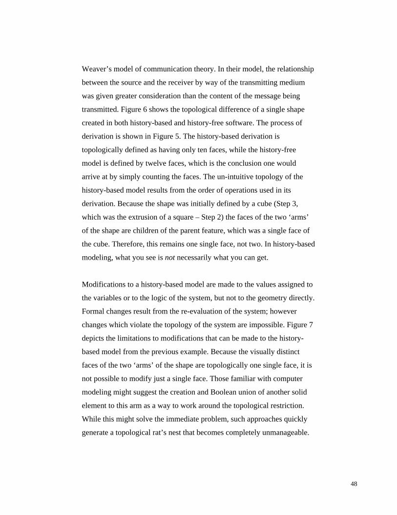
Modifications to a history-based model are made to the values assigned to
the variables or to the logic of the system, but not to the geometry directly.
Formal changes result from the re-evaluation of the system; however
changes which violate the topology of the system are impossible. Figure 7
depicts the limitations to modifications that can be made to the history-
based model from the previous example. Because the visually distinct
faces of the two ‘arms’ of the shape are topologically one single face, it is
not possible to modify just a single face. Those familiar with computer
modeling might suggest the creation and Boolean union of another solid
element to this arm as a way to work around the topological restriction.
While this might solve the immediate problem, such approaches quickly
generate a topological rat’s nest that becomes completely unmanageable.
48
1
2
3
4
5
6
7
8
11
22
33
44
55
66
77
8
X
Figure 7. If a change needs to be made to an aspect of model not represented by some node or set of nodes in the tree, then the model would need to be rebuilt in a way that would accommodate that change.
Because of their explicit associative-dependency, history-based systems
are often mistakenly considered a necessary precondition of a ‘parametric’
system. This is a misleading statement, and another example of the
problems that can arise from the superficial integration of tools developed
for and by other industries. A parametric system is any system which
provides for the assignment of independent, arbitrary variables (either set
values or functions) from which the instantaneous value of a particular
entity or entities is derived. The ability to define parameters is not
determined by the history-nature of CAD software.
49
The development and use of history-based systems in other industries is
based on the fact that the processes employed to generate form may be
more significant than the resulting form itself; this is not necessarily the
case in architecture38. In architectural design, the rationale behind a
model’s structure may be the result of individuals’ modeling habits, a lack
of modeling ability, or based on very particular design intentions.
Referring back again to the modeling example in Figure 5, the steps used
in the process of derivation were arbitrary, and not carefully considered. It
was just a quick and easy way to make the shape, which later proved to be
very problematic. Theoretically there is no way I could have known in
advance that I would later need to be able to modify the shape in a way
that was topologically impossible based on that initial process. The
history-tree captures and enforces the logic of the system, but the
reasoning as to why that particular logic was used is not part of the
system. This means that if I had employed the process of derivation shown
in Figure 5 in order to intentionally constrain the model in this way, there
would be no record of why. Therefore, even if the model and its
topological definition were successfully shared with another designer or
38 Current initiatives towards process representation, such as the work on Building Model
Repositories and Product Model Repositories being led by Chuck Eastman and others at the Georgia Institute of Technology, rely on the use of the carefully controlled use of a standardized, formal language to encode design methods. These methods are useful and effective for clearly understood and well-defined problems, the variability of which is constrained within predetermined limits, in much the same way that associative-dependency chains unambiguously bound the variability of “parametric” computer models. Malcolm McCullough nicely states the problem this way: “Parametrics work better in domains whose subject matter is engineered form itself – especially in mechanical components for complex assemblies such as vehicles. Parametric design works less well where physical configuration and performance are just the means, and a more emergent usage pattern is the end. Or, to put it the other way round, when the subject matter of design is more the social arrangements and less the mechanical assemblies used to house them. Parameterisation breaks down when the design problems are wickedly under- or overconstrained, or where the design variables are less obvious. Compared to an aeroplane part, even the aforementioned rote hotel room is less computable.”[12 p14-15]
50
consultant, they would still have no way of knowing whether the topology
was meaningful or arbitrary. Furthermore, the ability to exchange data
structures between different CAD software is a non-trivial problem, and at
the heart of the problem of technological interoperability. Most file
formats do not provide for the exchange of explicit topological hierarchies
or parameters. This will be discussed in greater depth later in this chapter.
The usefulness of associative-dependency based models is that they allow
designers to explore the extent of a particular derivations topological
variability, or logical bounds. Somewhat paradoxically, it is the fixed and
unambiguous nature of the data structuring behind these systems that
provides for a certain amount of design exploration. While often lauded
for their ‘flexibility’, it is these same explicit data structuring requirements
of contemporary CAD software that also distances the designer from the
“indispensable immediacy”39 of the design medium.
39 The term “indispensable immediacy” was used by Pegor Papazian in his 1991 Master’s
Thesis, Principles, Opportunism and Seeing in Design: A Computational Approach.[32 p45] Quoting at length: “Not all the intentions and constraints resulting in the creation of components (and their relationships) in a design document are made explicit in it. A computational system which compensates for this apparent shortcoming by extensive annotation and constraint management, runs the risk of losing the indispensable immediacy of the designer’s interaction with the document. Due to the overwhelming ubiquity of constraints, the designer needs not only the ambiguity of a document (an intersection of lines can be a cross or two L shapes) but also the arbitrariness inherent in it (a line which could satisfy the relevant constraints by being anywhere within a range of locations, is actually placed in one particular location and the designer’s subsequent interactions with it are a function of that particular location).” Bill Mitchell also addressed this topic in 1995 in his book Digital Design Media.[14 p376] Quoting at length again, “It makes little sense, then, to attempt organization of a design project around a comprehensive, fully integrated, three-dimensional assembly model from the very beginning – as many of the pioneering integrated computer-aided design systems attempted to do. The demands of this representation tend to force a designer’s attention to issues that are irrelevant at a particular stage of consideration and deflect it from issues that are more crucial.” And well before both of them, Vladimir Bazjanac came to exactly the same conclusion after working with computer aids to design in the 1970’s: “The experiment [to test theories of the inability of CAD to make designing more efficient] confirmed that the use of computer-aided models in a design only distracts the designer from his original task of designing the building.”[3 p23]
51
As indicated, the notion that design intent can be embodied in the
geometric and mathematical parameters of a computer model is also
incorrect. First, as shown in Chapter 3, architectural documentation does
simply represents what the design concept is, not why it is the way it is.
The difference is subtle but important. A design concept is an abstract or
theoretical construct that embodies the essential attributes of the design
ideas represented: the “what”. Design intent is the meaning or purpose of a
design: the “why”. The correlation with the various models of
communication presented in Chapter 2 should be fairly clear. To state that
rule schema capture intent is to equate topology with meaning or as
Shannon and Weaver and Saussure would assume signifier with signified.
As shown in the shape derivation examples above, meaning cannot be
encoded and topology cannot be assumed without explicit knowledge of
the process of derivation.
An early proponent-turned-critic of CAD, Vladimir Bazjanac stated,
“Information used in the design process always can be and usually is
subjected to personal interpretation. That interpretation is more significant
than the objectiveness of the reliability of the information itself.”[3 p22] If
something as simple as the dimension of a line could embody design
intent, then the shape experiments in Chapter 4 should have been easy for
people to do, and all the results should have been consistent. As the
evidence shows, this was not the case.
Proponents of a technological solution to the problems of the individual
interpretation (ambiguity) of information and interoperability in the AEC
industry advocate a new model for communication known as Building
Information Modeling (BIM). BIM is organized around the idea a single,
52
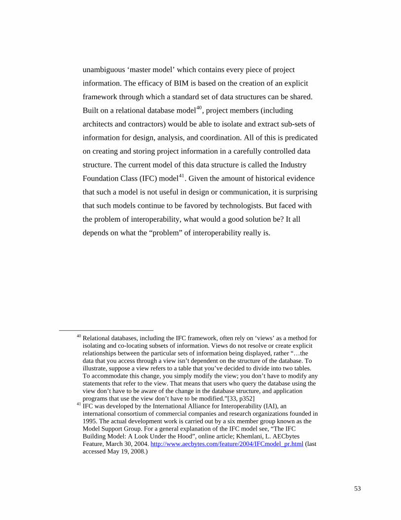
unambiguous ‘master model’ which contains every piece of project
information. The efficacy of BIM is based on the creation of an explicit
framework through which a standard set of data structures can be shared.
Built on a relational database model40, project members (including
architects and contractors) would be able to isolate and extract sub-sets of
information for design, analysis, and coordination. All of this is predicated
on creating and storing project information in a carefully controlled data
structure. The current model of this data structure is called the Industry
Foundation Class (IFC) model41. Given the amount of historical evidence
that such a model is not useful in design or communication, it is surprising
that such models continue to be favored by technologists. But faced with
the problem of interoperability, what would a good solution be? It all
depends on what the “problem” of interoperability really is.
40 Relational databases, including the IFC framework, often rely on ‘views’ as a method for
isolating and co-locating subsets of information. Views do not resolve or create explicit relationships between the particular sets of information being displayed, rather “…the data that you access through a view isn’t dependent on the structure of the database. To illustrate, suppose a view refers to a table that you’ve decided to divide into two tables. To accommodate this change, you simply modify the view; you don’t have to modify any statements that refer to the view. That means that users who query the database using the view don’t have to be aware of the change in the database structure, and application programs that use the view don’t have to be modified.”[33, p352]
41 IFC was developed by the International Alliance for Interoperability (IAI), an international consortium of commercial companies and research organizations founded in 1995. The actual development work is carried out by a six member group known as the Model Support Group. For a general explanation of the IFC model see, “The IFC Building Model: A Look Under the Hood”, online article; Khemlani, L. AECbytes Feature, March 30, 2004. http://www.aecbytes.com/feature/2004/IFCmodel_pr.html (last accessed May 19, 2008.)
Figure 8. Interoperability is typically presented as a people issue (left), but in reality it is a file extension issue.
Interoperability. Commonly, the problem of interoperability is framed as
a problem of communication among an ostensibly disorderly network of
AEC roles and responsibilities. With respect to technology, the actual
problem is one of exchanging information between a network of different
file formats and data structures. As my interviewee at SOM indicated, the
problem with data conversion is not simply one of information lost, but
also one of unwanted information gained.
McGraw Hill Construction Research and Analytics reported in 2007 in
Interoperability in the Construction Industry, Smart Market Report -
Design and Construction Industry that an estimated 3.1% of total project
costs are spent addressing issues associated with interoperability. Manual
re-entry of data was ranked as the main driver of increased costs due to
problems with software interoperability. “Less time drafting more time
designing”[28] was rated as the most significant factor influencing the
desire to use a BIM approach (later in this chapter I will present evidence
that promises of the ability of computer aids to design to fulfill this goal
54
have been made since CAD was invented). Ranking third on the list of
factors influencing the adoption of BIM is “BIM’s Ability to Improve
Communication with Clients/Others in Design and Construction
Process”.[28] My research indicates that one of the most significant
improvements to communication is not the conceptual framework behind
BIM, but simply the 3D visualization of various building components
concatenated in one model42.
The degree to which digital information may be repurposed is directly
related to the technological independence of the information. However,
since the use of technology in the AEC industry is ubiquitous, the default
solution is to try and impose standards. This is a generic problem in many
technology-dependent industries. Quoting from The Irwin Handbook of
42 When asked about how work was being coordinated on a large project which involved
several different contractors and sub-contractors, the person I interviewed at SHoP indicated, “They’re going to coordinate it all in BIM…it will be 3D coordinated. They'll do the construction BIM process, so, architects are…coordinating things to a certain extent, but they still can't tell them [fabricators] how to build it. We're [architects] just saying we're guaranteeing that we know it fits. We designed it in a way that its coordinated and we know that you can get all this stuff in here, but if the mechanical guy comes in and says ‘that's not the most efficient way for me to build this’, we can't force it. What we're doing is a diagram of how the systems work within a certain space, but then when it gets to means and methods, we can't tell them how to do that. So then there is a whole construction coordination process that goes on, and that's with the guys who sit over light tables with all that spaghetti stuff on a sheet and they say, ‘top of thing here and bottom of thing here’. But now its all happening in 3d. They model it based on shop drawings. We're doing that on a another project, we're offering a construction service where we're modeling all the shop drawings, but this is after our design contract is finished. We take all the shop drawings, and instead of just checking them [visually in 2d] now we're modeling them, that's our whole checking procedure. And then we're going to run collision detection on all the systems and see where there's clashes and interferences which will allow them to prefabricate more and put the systems up in pieces.”
Additional evidence was found in an article regarding the design and construction of a new US Courthouse in Rockford, IL. Kirk Stuaan of the design firm PSA-Dewbury stated “BIM is a great visualization tool, but it does not replace the dialog that needs to occur between team members within a given discipline. While the communication does not always happen as it should, there is no disputing the value of seeing the actual elements in the 3-D building space.” (my emphasis) [29].
55
Telecommunications: “The desire for standards and the desire for
technical progress can often conflict because standards can not be set until
technology has been proven through practice, and the only realistic way to
validate that proof is through extensive and widespread use that has not
yet been standardized.”[6 p17-18]
The majority of attempts to resolve this problem in design technology can
be categorized as follows: committee-based, standards-based, market-
based, and open-source. Committee-based solutions such as the Initial
Graphics Exchange Specification (IGES), and the STandard for the
Exchange of Product model data (STEP) have suffered from the retarding
effects of bureaucratic decision-making, slowing their ability to keep pace
with rapid changes in technology. Attempts to create industry standard
data structures by commercial geometry kernel providers have failed due
to the equalities of their readily available, high-quality products (ACIS,
Parasolid, etc.). Market-based approaches by software vendors in the form
of all-in-one CAD/CAM/CAE packages such as CATIA (and now the
Autodesk suite of products) result in prohibitively expensive software and
licensing costs, and the need for dedicated experts to operate the software
with no guarantee of the software being the best choice for every job.
Because no single obvious standard has emerged for digital modeling,
affiliate programs through which software developers encourage third-
parties to develop additional software functionality via plug-ins and APIs
(Application Programming Interfaces) have not been widely effective. The
most recent standards model is the aforementioned committee-based
Industry Foundation Class (IFC) framework.
56
BIM and The Toolmakers Paradigm43. The Toolmakers Paradigm is a
story that functions as an analogy to draw out the implications of those
models of communication which assume that symbols and their meanings
are determinate and unambiguous (i.e. Shannon and Weaver, Saussure). In
the beginning of The Toolmakers Paradigm, Michael Reddy suggests that
when communicating, we are like people isolated in slightly different
environments.[34 p171] In the story, he envisions a circular compound
which is broken up into discrete pie-shaped sections. The environment in
each section is slightly different, and there is only one inhabitant in each
section. The only means of communication between sections is through an
abstract piece of machinery at the center of the overall compound which
can only deliver small sheets of paper from one environment to another. In
my research, this is the exchange of architectural documentation. Reddy
tells us that the inhabitants use this machinery to exchange “crude sets of
instructions” for making things useful to their survival. Reddy stresses that
the inhabitants do not have knowledge about the environments of the other
sections or their inhabitants. In the AEC industry, although the various
domains are closely related, as are Reddy’s toolmakers, they do not
necessarily have a clear understanding of each others’ roles and
responsibilities.
Over the course of the story, the inhabitants attempt to send blueprints for
the making of tools they have created and which they find very beneficial
in their environment. Implicit in the blueprints are certain assumptions
about the other environments, such as the availability of common
materials with which to construct the tools. This is not the case. Confusion
ensues and further assumptions are made about the lack of each neighbors’
43 See [34].
57
intelligence. However, after much frustration the inhabitants begin to think
that perhaps all is not the same elsewhere in the compound and, taking this
into account, adjust the way they communicate. Rather than assuming the
meanings of their messages are unambiguous the toolmakers begin to
annotate their diagrams to indicate the type of materials they have used in
making their tools. Additionally, those in receipt of the instructions also
begin to annotate and return the instructions where they find the
instructions unclear. This process of design and constructing meaning, of
making and re-making, is a clear example of the effort necessary in any
successful exchange of information. This is the model Peirce was
describing and Papert was observing in how people learn. The toolmakers’
method of validation is directly analogous to the professional obligations
of architects and contractors described in Chapter 3. All parties involved
in design and construction projects not only interpret the conceptual
information they receive but must also prove, or validate, their
interpretation. They do so by re-presenting information as a series of
fabrication and construction procedures.
But the story doesn’t end there; Reddy later introduces an evil wizard who
casts a spell of forgetfulness on the toolmakers. Under the wizard’s spell,
after completing the construction of a tool, the toolmaker to instantly
forgets that it was they who built the tool. Instead, the toolmaker believes
that the completed tool was received intact from another toolmaker
through some new trickery of the compound’s communication machinery.
Because the toolmakers could no longer recall whom it was that
constructed the tools, they lost any sense of responsibility for its
craftsmanship. As a result they began to blame their neighbors for defects
in construction. Furthermore, without the ability to develop a sense of
pride or achievement in the results of their toil (since they could not recall
58
that it was their seeing and thinking and doing that created the tool to
begin with), they spent less time and effort constructing the tools. This led
to greater defects, more blame, and even less effort. Reddy concludes the
story by stating that “Human communication will almost always go astray
unless real energy is expended.”[34 p174]
AEC Database
(BIM)
Architect
Client
Construction Manager
Permitting Agency
EngineersConsultants
Facilities Manager
FabricatorsAEC
Database (BIM)
Architect
Client
Construction Manager
Permitting Agency
EngineersConsultants
Facilities Manager
Fabricators
Figure 9. Diagram of the compound from The Toolmakers Paradigm (left). Diagram of the database (BIM) solution to interoperability for the AEC industry.
Reddy explicit notes the failure of Shannon and Weavers model to account
for ‘radical subjectivity’ by assuming the indivisibility of signifier-
signified relationship. As Reddy points out, “Signals do something. They
cannot contain anything.”[34 p172, 184] It is interesting to note then, that
the diagrams most often used to extol the benefits of BIM) in design and
construction communication are almost identical to Reddy’s diagram of
the Toolmakers’ compound (Figure 9). Based on the case studies and
shape experiments conducted for this thesis, such an approach is
antithetical to the effective communication of design and construction
information. It is not surprising then that most of the BIM “tools” being
developed for architects are directed towards the product of design
documentation, rather than the production of design information. The
59
developers of such software believe that the process of making is implicit
and unambiguously described by the product made. The developers of
Revit Architecture 2008, a so-called BIM tool, authored an instructional
textbook in which they encourage the following approach to using the
software:
“Begin with the end in your mind.” 44
Productive and Unproductive Acts. Acts of making and re-making are
fundamental to the way that architects and contractors relate to design
information. Architects produce a design description, or state description,
of a desired object. Through communication with the contractor the design
description is interpreted and translated into a construction description.
The contractor’s documentation dictates the means and methods of the
work to be performed, and the acceptable tolerance range of the outcome
of that work. Goodman compared these various descriptions to musical
scores, and their performance.[5 p218-219] While Goodman points out the
positive aspects of the repetition of such performances, others see them as
wasteful. For example, in the book Architecture in the Digital Age, Branko
Kolarevic points to the automation of “highly redundant and utterly
inefficient” acts of making and re-making as the promise of contemporary
CAD/CAM/CAE technology.[9 p60] These promises are nothing new.
In 1975 Vladimir Bazjanac noted that one of the reasons that practitioners
were (then) still enamored with computer aids to design was the general
belief that, “Computer applications will ‘free’ the designer from
distracting and unproductive activities and allow him to devote more time
44 From Introducing Revit Architecture 2008: BIM for Beginners [8] p15.
60
to design.”[3 p18] These activities included the “noncreative tasks that are
considered wasteful of [their] time (like drafting, manipulation of
information, maintenance of an extensive information system, etc.).”[3
p18] Bazjanac had initially shared this early enthusiasm. After ten years of
working with CAD technology in professional practice, his enthusiasm
turned to doubt. He noted that the flexible interpretations and intuitive
models of human designers were difficult to capture within the rigid
framework of fixed data constructs. The importance of information to
those involved in design and construction “…was not its content but how
he used it.”[3 p21] Bazjanac concluded that in practice, the importance of
technology was that it provided architects with what they considered to be
an objective mechanism for substantiating their design solutions. With
respect to a project for which Bazjanac was tasked with creating a
simulation for pedestrian circulation in a multistory educational building
he noted, “What they [the designers] expected from a computer model was
credibility, not precision.”[3 p21] This suggests that by itself the presence
of information and its structure do not inherently benefit design. Rather, it
is how the information is used that is most significant. This is a further
condemnation of those models of communication which do not address
ambiguity. This conclusion is also supported by the case studies I
conducted along with the results from the shape experiments.
Given that Bazjanac was writing about these issues only ten years after the
introduction of CAD into the professional practice of architecture, it is
surprising that the same promises are being made with respect to
contemporary technology. In 2007, the developers of Revit Architecture
2008 stated that their software would allow the computer to “…take
responsibility for redundant interactions and calculations, providing you,
the designer, with more time to design and evaluate your decisions.”[8 p7]
61
I believe that the nature of these assertions is indicative of a failure to
understand the actual problem to which its proponents are attempting to
apply technology. Implicit in all of these discussions is the assumption that
any and all repeated acts in design and communication are “highly
redundant and utterly inefficient”.[9 p60] My research counters this
assertion, indicating that acts of making and re-making are fundamental to
the way that architects and contractors relate to design information.
Within everyday practice the contractual obligations of the architect,
contractor, and sub-contractors are often blurred and/or misunderstood.
The requirement of contractors to produce their own set of construction
documents based on the architectural construction documents is an act of
seeing, thinking, and doing. This is an act or repetition which
demonstrates the contractor’s ability to comprehend and comply with the
design concept. I submit that any determination of the usefulness of a
computer aid to design must ask the following questions: What is wasteful
repetition in design and construction? And, what is productive repetition
in design and construction?
Both Chuck Eastman of the Georgia Institute of Technology and Richard
Sennett of MIT, the London School of Economics, and NYU have
recently published on the subject of repetition in processes of design and
making45. Eastman’s notion of making is based on pre-determined parts
and systems of production, similar to the process described in Christopher
Alexander’s Notes on the Synthesis of Form.[2] Eastman takes his
examples from manufacturing assembly lines. He implies that acts of
45 See Eastman, Chuck... [et al.]. (2008) BIM handbook : a guide to building information
modeling for owners, managers, designers, engineers, and contractors. (Hoboken, N.J. : Wiley) and Sennett, Richard. (2008) The Craftsman. (Yale University Press).
62
repetition are blind, mindless procedures meant to produce exactly the
same result every time. For Eastman, seeing and thinking have no impact
on doing, other than to screw it up. Eastman’s acts of repetition present an
ideal opportunity for automation because the feedback from every discrete
act can be captured in a system based on the Boolean logic of 0s and 1s;
the result of the act is either right or wrong.
Sennett’s definition of the craftsman also highlights the notion of
repetition; however, he draws examples from music. Sennett asserts that
the repeating of actions (the playing of musical scales for instance) is a
fundamental part of learning for musicians. Musicians initially use
repetition to develop tacit knowledge by training their hands, mind, and
eyes to work in concert. The goal is to gain control of the process. This is
similar to the anecdote given by SHoP on their use of multiple software to
develop an understanding of the rules guiding the design of a brick façade.
Once tacit knowledge has been developed the goal of repetition is no
longer conformity, but variation. Repetition at this point becomes iteration
- a method of exploration and continued learning through subtle and
controlled variations. Likewise, designers rely on iteration to study the
variability of their designs, as well as to validate their proposed solution.
In Sennett’s world, deviations from the expected results become
opportunities for new insight, rather than problems which require de-
bugging.
Repetition for Eastman wastefully consumes time and resources.
Eastman’s model works because the elements on which it operates are pre-
selected for their ability to make the model work. In Sennett’s example,
repetition is also time and resource intensive, but it is the source of
learning and knowledge, and therefore indispensable. Eastman’s
63
assembler has its roots in Minsky’s production systems.[13] Sennett’s
craftsman is rooted in the seeing and doing of Shape Grammars.[24]
x = t(x)
x = t(x)
x
see
think
do
do
think
see
Conscious Loop / Tacit Loop
x
t(x)
g(t(x))
f(g(t(x)))
Assembler(Eastman)
Craftsman(Sennett)
Production (Database) Approach Shape Grammar Approach
x = t(x)
x = t(x)
x
see
think
do
do
think
see
Conscious Loop / Tacit Loop
x
t(x)
g(t(x))
f(g(t(x)))
Assembler(Eastman)
Craftsman(Sennett)
Production (Database) Approach Shape Grammar Approach
Figure 10. Productive and unproductive acts of repetition.
By determining those acts of repetition caused by particular data
structures, and those acts of repetition which challenge tacit knowledge,
we can assess the criteria with which to develop computer aids to design
and construction. I conclude that productive repetition is generally defined
as those acts which contribute to a deeper understanding of design and
construction communication. In contrast, unproductive acts of repetition
are those necessitated solely by technological limitations.
64
7. Conclusion
“Sometimes a line is just a line. But the same line can represent the
edge of a pyramid, the boundary of a field, or the path a crow flies.
Knowledge about one transfers to the other.”
- Leonard Mlodinow, Euclid's Window, p.17
The ability of a design concept to persist across representational media is
fundamental to the communication of design and construction
information. By moving away from material-dependent design
manifestations Computer Aided Design (CAD) established a means for
capturing, storing, and processing the information necessary to re-present
a design object as explicit relationships between abstract-symbolic
entities. However, the persistence of design information relies also on a
shared culture of design and construction, not just good technology.
The introduction of CAD representations placed a new set of requirements
on the producers of design information “quite independent” of the design
object being described46.[26 p75] Twenty years later, in The Vitality of
Digital Creation, Timothy Binkley states that our ability to communicate
orally with respect to digital technology lags behind our ability to use it in
new and creative ways, and until “our language catches up with our
46 “To a large extent it has turned out that the usefulness of computer drawings is precisely
their structured nature and that this structured nature is precisely the difficulty in making them. I believe that the computer-aided design community has been slow to recognize and accept this truth. An ordinary draftsman is unconcerned with the structure of his drawing material. Pen and ink or pencil and paper have no inherent structure. They only make dirty marks on paper. The draftsman is concerned principally with the drawings as a representation of the evolving design. The behavior of a computer-produced drawing, on the other hand, is critically dependent upon the topological and geometric structure built up in the computer memory as a result of drawing operations. The drawing itself has properties quite independent of the properties of the object it is describing.”[26 p75]
65
creativity” we will be left to “speaking about computers in paradoxes”.[4
p108] Binkley’s claim about our inability to speak of technology with the
same facility with which we operate it can be construed as either a positive
or negative state of affairs based on your opinion of paradoxes in design. I
believe the paradoxes Binkley considers problematic are in fact
fundamental to design communication. By creating representations, we
externalize the division between what we see and what we (think) we
know. Representational media provide us with the means and methods to
explore new ideas and introduce new metaphors that suggest new ways of
seeing and thinking and doing.
The exclusionary nature of any representational medium is a key aspect of
it usefulness in seeing and doing47. Isolating, or framing, discrete subsets
of design information reveal implicit or subtle aspects of the design, and
design logic, that may not obvious in another context. This is both the
power and danger of representation. By blocking out some information, it
allows to see things we otherwise might miss. At the same time, if we do
not remain cognizant of all that is being blocked out, we may lose the
overall context, and thereby distort the meaning, of that which we are
looking at.
What often saves us is the effort involved in the integration of mind, hand,
and eye. Through the repetition of creative acts, we introduce the
opportunity for reinterpretation and feedback. A mistake of the hand may
open the eye to see differently and in turn trigger the mind to think of new
47 “A representation is a formal system for making explicit certain entities of types of
information, together with a specification of how the system does this…Thus, there is a trade-off; any particular representation makes certain information explicit at the expense of information that is pushed into the background and may be quite hard to recover.[11 p21]
66
design possibilities. Design aids should provide the means for such
decoupling of symbol and concept, enabling what Ackerman refers to as
“creative symbol-use”.[1] Unaided, it is unlikely that we would be capable
of conceiving or recognizing uniquely new relationships that may be
implicit in a design. All too often we recognize only what we have seen
before, and we find only what we expect to find48. This is both the good
and the bad of most digital design technology. Regardless of how many
things you may see, the computer doesn’t see anything at all49.
Current standards-based approaches rely on this blindness by suggesting
the possibility of disambiguating information through a strict data model.
The problem is expert knowledge which does not fit the standardized
model, or is not accounted for in the model, stands to be lost. Furthermore,
a rigid and inflexible vocabulary may actually lead to the dis-integration
of meaningful communication between design and construction
information. There are several reasons for why these approaches are likely
to fail. First, they all have in the past. Second, they are built on the
assumption that meaning can unambiguously be connected with symbolic
information. Third, these models assume and that individual interpretation
is not necessary in the communication of design and construction. And
lastly, these approaches assume that the solution must come from the
formulation of a new model, rather than a new mindset.
48 Wittgenstein referred to this as the limitation of expectation, “Expectation is connected
with looking for. My looking for something presupposes that I know what I am looking for, without what I am looking for having to exist.” [Wittgenstein, L. Philosophische]
49 “In a digital medium…the two functions of storing and displaying information are relatively independent. The fundamental purpose of a digital medium is to keep track of sometimes enormous collections of organized numbers. The numbers need to be exhibited somehow to have meaning, but since they are abstractions, they are not endemic to any particular medium of expression.”[4 p110]
67
Architects are trained and practiced in the means and methods of design
and design is an act of seeing, thinking, and making. This is the design
mindset. It is an ephemeral process involving the use of the eye, the mind,
and the hand. Whether it is a pencil or a mouse or a touch-screen, the
design aids we employ must facilitate the work of our hands in
coordination with our eyes and mind in a process of learning-by-seeing-
by-doing. The role of the users of design technology must be in the
productive exploitation of the unique characteristics of digital media to
enhance communication.
“In each period of our history, design and communication have evolved
synchronously with the technology of the time. Each new medium has
extended our sense of reality and each has looked to its predecessor for
language and conventions, referencing and adapting its characteristics
until its unique capabilities can be explored and codified.” Muriel
Cooper, 1989.
But the work doesn’t end there. Once the unique capabilities of each new
medium are explored and codified, it is the responsibility of practitioners
(users) of that medium to reflect on its usefulness (productivity) in design
and communication. The ways in which individuals to draw and model
using CAD software do not necessarily contain or convey any information
regarding their design intent. If digital technology is truly to be an aid to
design, then it must act as a digital facilitator between the analog
processes of designing and constructing. It must not arbitrarily compel
designers to work within the strictures of its pre-defined data constructs if
they result in unproductive repetition. It must instead facilitate productive
acts of making and re-making. A complete understanding of what
constitutes productive and unproductive acts is not to be inferred from this
research. However, these notions are meant to be used as criteria with
68
which to judge the usefulness of computer aids to design. The adoption of
CAD software developed by and for other industries has shown benefits in
the realization of complex form. However, in addition to computational
robustness and formal dexterity, architects have also inherited the
processes, assumptions, and metaphors of other industrial cultures
embodied in the software. Like The Toolmakers Paradigm, my research
suggests that the cultural assumptions embedded in such technology play a
significant role in the way we understand, and employ computer aids to
design and construction. And the conception we develop around our roles
and responsibilities as designers and contractors has a dramatic impact on
the mental models we use to interpret information.
By re-centralizing the link between seeing and thinking and doing,
architects will re-join the ranks of process creators, rather than stagnating
in their current role of process consumers. The implications are the
development of actual computer aids to design, rather than simply digital
design tools.
Design Construction
Analog - Digital Digital - Analog
Design Construction
Analog - Digital Digital - Analog
69
70
Illustration Credits
All illustrations by the author unless otherwise noted.
71
72
Bibliography
[1] Ackerman, Edith. (2004) “Constructing Knowledge And Transforming.” in A learning zone of one's own: Sharing representations and flow in collaborative learning environments. M. Tokoro and L. Steels (Eds.). (Washington, DC. IOS Press) p. 15-37
[2] Alexander, Christopher. (1964) Notes on the Synthesis of Form. (Harvard University Press: Cambridge, MA).
[3] Bazjanac, Vladimir. (1975) “The Promises and Disappointments of Computer-Aided Design” in Negroponte, Nicholas (eds.) Reflections on Computer Aids to Design and Architecture. (New York: Petrocelli / Charter) p.17-26
[4] Binkley, Timothy. (1997) “The Vitality of Digital Creation.” The Journal of Aesthetics and Art Criticism, Vol. 55, No. 2, Perspectives on the Arts and Technology (Blackwell Publishing), p. 107-116
[5] Goodman, Nelson. (1976) Languages of Art. 2nd ed. (Hackett Publishing Company.)
[6] Green, James H. (2005) The Irwin Handbook of Telecommunications. 5th ed. (New York: McGraw-Hill.)
[7] Hamilton, Paul. “A Primer on MCAD Modeling Technology, Part 2: Design Intent is Not Necessarily in the Eye of the Beholder.” CADCAMNet, July 26, 2007, http://www.newslettersonline.com/user/user.fas/s=63/fp=3/tp=47?T=open_article,959682&P=article (last accessed May 21, 2008.)
[8] Krygiel, Eddy, Greg Demchak, and Tatjana Dzambazova. 2007. Introducing Revit Architecture 2008. (Pap/Cdr. Sybex.)
[9] Kolarevic, Branko. (2003) “Information Master Builders” in Architecture in the Digital Age: Design and Manufacturing. 1st ed. (New York, London : Spon Press).
[10] March, L. (1976) “Introduction” in L. March (ed.) The Architecture of Form (Cambridge: Cambridge University Press.)
[11] Marr, David. (1982) Vision: A Computational Investigation into the Human Representation and Processing of Visual Information. (San Francisco: W.H. Freeman.)
[12] McCullough, Malcolm. (2006)."20 Years of Scripted Space" Architectural Design v.76 no.4 July/August 2006, "Programming Cultures: Art and Architecture in the Age of Software" (Wiley Interscience). p. 12-15
[14] Mitchell, William J. and McCullough, Malcolm. (1995) Digital Design Media, 2 ed. (Wiley & Sons).
[15] Mlodinow, Leonard. (2001) Euclid's Window: The Story of Geometry from Parallel Lines to Hyperspace. (New York: Free Press).
[16] Saussure, Ferdinand de. (1972) Course in General Linguistics. Harris, Roy (trans.) Bally, Charles and Sechehaye, Albert (eds.) (London: Duckworth 1983).
[17] Scheurer, F. "Getting Complexity Organized Using self-organisation in architectural construction"; in Automation in construction 16, 2007 p. 79
[18] Schön, Donald A. (1988) Designing: Rules, types and words. Design Studies v.9, no. 3 (Elsevier Science Ltd). p. 181-190
[19] Schön, Donald A. (1992) Kinds of seeing and their function in designing. Design Studies v.13, no. 2 (Elsevier Science Ltd.) p. 135-156
[20] Shannon, Claude E. and Weaver, William. (1949) The Mathematical Theory of Communication (Urbana: University of Illinois Press.)
[21] Stiny, George. and Gips, James. (1972) "Shape Grammars and the Generative Specification of Painting and Sculpture," in C. V. Freiman, ed., Information Processing 71 (North Holland, Amsterdam). pp. 1460-1465.
[22] Stiny, George. (1975) Pictorial and Formal Aspects of Shape and Shape Grammars (Birkhauser, Basel).
[23] Stiny, George. (1980) “Introduction to Shape and Shape Grammars” in Environment and Planning B: Planning and Design 7: p343-351.
74
[24] Stiny, George. (2006) Shape: Talking About Seeing and Doing. (Cambridge, Mass: MIT Press.)
[25] Sutherland, Ivan. (1963) Sketchpad, A Man-Machine Graphical Communication System MIT PhD. Thesis.
[26] Sutherland, Ivan. (1975) “Structure in Drawings and The Hidden Surface Problem” in Negroponte, Nicholas (eds.) Reflections on Computer Aids to Design and Architecture. (New York: Petrocelli / Charter) p.73-77
[27] Whitehead, Hugh. (2003) ‘Laws of Form’ in Architecture in the Digital Age: Design and Manufacturing Kolarevic, Branko (ed.) (Spon Press: New York / London). p. 81-100
[28] Interoperability in the Construction Industry, Smart Market Report -Design and Construction Industry, 2007 Interoperability Issue (McGraw-Hill; Oct 2007) p. 4-5
[29] “Modeling Saves Money, Time: Upfront training costs on building information modeling prove worthwhile.” CBP Magazine (no date) http://www.cbpmagazine.com/article.php?articleid=226 (last accessed May 21, 2008.)
[30] Peirce, Charles Sanders. (1931-58) Collected Writings (8 Vols.) Hartshorne, Charles. Weiss, Paul. Burks, Arthur W. (Eds.) (Cambridge, MA: Harvard University Press).
[31] Simon, Herbert A. (1996) The Sciences of the Artificial, 3rd Edition. (MIT Press: Cambridge, MA).
[32] Papazian, Pegor H. (1991) Principles, Opportunism and Seeing in Design: A Computational Approach, MIT Thesis (S.M.Arch.S.)
[33] Syverson, Bryan. (2002) Murach's SQL for SQL Server. (Pap/Cdr. Mike Murach & Associates.)
[34] Reddy, Michael J. (1993) “The conduit metaphor: A case of frame conflict in our language about language.” in Metaphor and Thought. 2nd Edition, Ortony, A. (ed.) (Cambridge University Press).