Building Triggers O ne of the first camera hacks I ever performed was the extension of the remote trigger release on my Canon EOS SLR: I extended it to shoot pictures of myself on roller skates from a distance. The hack was so easy I soon learned to make trigger switches as well. Trigger switches and extensions can serve purposes other than self-portraiture. You might want to set up your camera gear in a remote location to photograph birds and other animals in action. Sometimes I would set my camera in my ham- sters’ cages to capture their daily activities. Another popular remote trigger application is shooting sporting events. Photographers have been known to rig their gear inside hockey rinks and even in goalie boxes, generally using wireless triggers. But nothing is stopping you from running wired camera equipment to the basketball hoop in your yard. Mounting your camera there can render some awesome pictures of your kids playing basketball. This chapter helps you make trigger switches and extend their ranges. If you have trigger switches from older generation cameras, you may be able to adapt them for use on your new state-of-the-art cameras. This chapter shows you how to make those adapters. Most single-lens reflex (SLR) cam- eras have a built-in shutter trigger port, and you connect to this port directly. But most point-and-shoot (P&S) cameras lack this nifty feature. On these cameras, you hack the camera itself and wire a trigger port directly to the shutter switch. This trigger port will use the same interface as the one available on SLRs, so if you have both types of camera systems, you can use the same remote trigger switch and extender for all your gear. Making a Wired Remote Trigger Most SLRs, even entry-level ones, have a remote shutter release socket so you can shoot pictures without actually touching the camera body. The remote trigger is used often in long-exposure photography, where even a small amount of vibration can introduce blurriness into the image. As steady as your hands are, they are not machines, and, therefore, they are prone to tiny movements that you may not be aware of until you view your picture. With a wired remote trigger release, the camera body can be mounted on a tripod, and you operate the camera through the wired remote trigger. ˛ Making a Wired Remote Trigger ˛ Making a Delay Trigger ˛ Making an Interval Trigger ˛ Connecting the Triggers to a Point- and-Shoot Camera ˛ Extending the Remote Switch chapter in this chapter COPYRIGHTED MATERIAL
Transcript
Building Triggers
One of the first camera hacks I ever performed was the extension ofthe remote trigger release on my Canon EOS SLR: I extended it toshoot pictures of myself on roller skates from a distance. The hack
was so easy I soon learned to make trigger switches as well. Trigger switchesand extensions can serve purposes other than self-portraiture. You mightwant to set up your camera gear in a remote location to photograph birdsand other animals in action. Sometimes I would set my camera in my ham-sters’ cages to capture their daily activities. Another popular remote triggerapplication is shooting sporting events. Photographers have been known torig their gear inside hockey rinks and even in goalie boxes, generally usingwireless triggers. But nothing is stopping you from running wired cameraequipment to the basketball hoop in your yard. Mounting your camera therecan render some awesome pictures of your kids playing basketball.
This chapter helps you make trigger switches and extend their ranges. Ifyou have trigger switches from older generation cameras, you may be ableto adapt them for use on your new state-of-the-art cameras. This chaptershows you how to make those adapters. Most single-lens reflex (SLR) cam-eras have a built-in shutter trigger port, and you connect to this portdirectly. But most point-and-shoot (P&S) cameras lack this nifty feature.On these cameras, you hack the camera itself and wire a trigger port directlyto the shutter switch. This trigger port will use the same interface as the oneavailable on SLRs, so if you have both types of camera systems, you can usethe same remote trigger switch and extender for all your gear.
Making a Wired Remote TriggerMost SLRs, even entry-level ones, have a remote shutter release socket soyou can shoot pictures without actually touching the camera body. Theremote trigger is used often in long-exposure photography, where even asmall amount of vibration can introduce blurriness into the image. Assteady as your hands are, they are not machines, and, therefore, they areprone to tiny movements that you may not be aware of until you view yourpicture. With a wired remote trigger release, the camera body can bemounted on a tripod, and you operate the camera through the wiredremote trigger.
˛ Making a WiredRemote Trigger
˛ Making a DelayTrigger
˛ Making an IntervalTrigger
˛ Connecting theTriggers to a Point-and-Shoot Camera
˛ Extending theRemote Switch
chapter
in this chapter
05_596519_ch01.qxd 8/19/05 12:34 PM Page 3
COPYRIG
HTED M
ATERIAL
4 Part I — Hacking Cameras
In astrophotography, exposure can take several minutes. If you had to operate the camera shutter with your hands on your camera’s shutter button, they would probably be shaking likemad after five minutes. Holding the shutter button down for a long time is extremely tiring.Fortunately, many remote shutter triggers can be locked in the down position. An oldermechanical trigger without the locking feature can be taped instead.
Remote shutter triggers are usually optional accessories for SLRs. They can cost anywherefrom five dollars for a mechanical version to several hundred dollars for a super fancy electronicversion. In the following sections, you build your own simple remote trigger so you understandhow a remote trigger works. This knowledge will help you to build fancier timing triggers andmultiple-camera triggers in the later sections of this chapter.
FIGURE 1-1: This picture of the moon was shot with a telescope and a camera. Both the telescope and camera were mounted on their own tripods. Vibration was still a major issue, so a wired remote and mirror lock-up were used.
05_596519_ch01.qxd 8/19/05 12:34 PM Page 4
5Chapter 1 — Building Triggers
How Does a Remote Trigger Work?On most of today’s cameras, a remote trigger works simply by closing an electrical circuit totrigger the shutter. This simple concept is shown in Figure 1-2. The wired remote is simply aswitch extended from the camera body.
This chapter makes extensive use of circuit diagrams. See Appendix B for a list of circuit symbols.
FIGURE 1-2: A schematic of the wired remote shutter trigger
A camera that has auto-focus (AF) capability generally has a two-position shutter trigger. Thefirst position—reached when you press the trigger halfway down—closes the circuit for theauto-focus function. The second position—reached when you press the trigger all the waydown—closes the shutter circuit. A wired remote trigger moves these two functions off the cam-era, as shown in Figure 1-3. Most Canon SLRs use this simple circuit for remote triggering.
FIGURE 1-3: A schematic of the wired remote shutter trigger with AF function
Shutter
Wired remote trigger
AF
Wired remote trigger
05_596519_ch01.qxd 8/19/05 12:34 PM Page 5
6 Part I — Hacking Cameras
Nikon SLRs use a slightly more complex circuit. The shutter circuit is simply an open/closecircuit, like that shown previously in Figure 1-2. But the AF circuit is an open/close switchalong with three 1N4148 diodes wired in series. The Nikon wired remote trigger circuit isshown in Figure 1-4.
FIGURE 1-4: A Nikon wired remote shutter trigger with AF function
Parts You NeedYour local electronic store carries all of these parts. I prefer Radio Shack because the stores areeverywhere. You can also order the parts online from RadioShack.com. I have listed the RadioShack part numbers for your convenience.
� Mini SPST Momentary Switch (275-1547)
� SPDT Submini Slide Switch (275-409)
� 3⁄32" Submini Phone Jack (274-245)
� 20-gauge wire (278-1388)
� Mini Project Enclosure (270-288)
A 2.5mm jack is the same size as a 3⁄32" jack.
There are many different types of switches (see the “Switch Terminology” sidebar). Each oneserves a slightly different purpose. Sometimes, two types of switches can be used for the samepurpose. For this project, I chose to use two momentary switches and a slide switch. The nor-mally open momentary switch (see Figure 1-6) is similar to the on-camera shutter button. Anormally open momentary switch requires that you hold down the switch to close the circuit.As soon as you let go of the switch, it opens the circuit again.
Shutter
Wired remote trigger
AF
05_596519_ch01.qxd 8/19/05 12:34 PM Page 6
7Chapter 1 — Building Triggers
Canon E3 Connector
The Canon RS60-E3 remote control, used on Canon EOS cameras, is a two-position switch justlike the shutter release on the Canon EOS series. Pushing the button down halfway causes thecamera to focus, while pushing the button down all the way causes the camera to release itsshutter. The wired remote control transmits the signal though a standard 2.5mm (sub-mini)audio head. The contacts on the head are numbered in Figure1-5.
FIGURE 1-5: The E3 connector pins
When the button on the remote control is pushed halfway, contact sections 1 and 2 are shortedtogether, causing the camera to focus. When the button on the remote control is pushed all theway, all three contact sections are shorted together, causing the camera shutter to be released.Pin 1 is actually the ground connector. Therefore, pin 1 and pin 3 cause the camera to trigger.
When you build your own camera interface, you can split the auto-focus and shutter releasefunctions by using two switches (using two independent circuits).
05_596519_ch01.qxd 8/19/05 12:34 PM Page 7
8 Part I — Hacking Cameras
FIGURE 1-6: Momentary pushbutton switches
Although this switch is appropriate as a shutter release for high-shutter-speed pictures, itwould be tiring to hold down a momentary switch for a long time (minutes or hours), suchas during a bulb exposure. To relieve you from having to hold the button down, most remotetriggers have a locking feature that holds the button down for you. I have chosen a slide switch(see Figure 1-7) to simulate that feature in this project. When you begin the exposure, slidethe switch to on. When you are done with the exposure, slide it to off.
Bulb exposure is the term that describes what happens when you control the shutter’s openingand closing without using the camera’s shutter speed timer. It’s generally used for a long expo-sure in astrophotography and night photography.
05_596519_ch01.qxd 8/19/05 12:34 PM Page 8
9Chapter 1 — Building Triggers
FIGURE 1-7: Slide switches
In this project, I chose a mini–project enclosure (see Figure 1-8) and a bunch of sub-mini partsto fit into it. These small parts help create a small remote trigger. A smaller remote trigger iseasy to carry around and doesn’t take up too much space in your camera bag. I also chose aplastic case because they are generally easier to work with than metal cases. It’s easier to drilland shape plastic than metal.
Most photographers like to have a small, wired remote. I’ve noticed that there seems to be ageneral consensus that smaller is better, and there’s nothing wrong with that. In fact, I picked avery small project case and a lot of sub-mini parts for this project. But you might consider abigger box to fit bigger switches for action events. If you have rigged a camera in a hockeyarena by the goal box, you probably don’t want to miss a shot because you are fiddling for abutton on your tiny remote. You might want to rig up a table-size remote where the button isthe size of your hand, so that you can pound on the buttons during the excitement of the game.
05_596519_ch01.qxd 8/19/05 12:34 PM Page 9
10 Part I — Hacking Cameras
FIGURE 1-8: A small project box
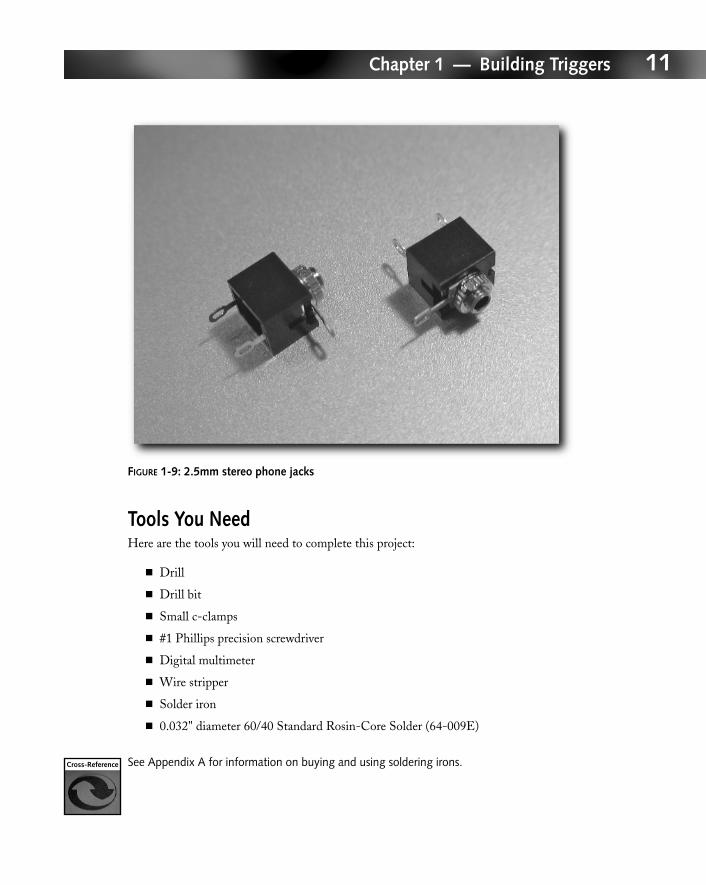
For interfacing, I chose a 3⁄32" (2.5mm) stereo phone jack (refer to the “Canon E3 Connector”sidebar), shown in Figure 1-9. This is the same interface that is used on entry-level CanonEOS SLRs, so you can easily attach this wired remote trigger to them. This interface is com-mon on cellular phone earpieces and other electronic components as well. Both female andmale versions are common and easy to source. This is the preferred interface method comparedto the proprietary interface found on higher-end Canon EOS SLRs, Nikon SLRs, and others.Later in this chapter I show you how to adapt this simple interface to the proprietary interfacesso that you can use the same remote trigger with the more advanced cameras.
You need some electrical wires to make the connections between the switches and the interfacejack. You might already have some leftover wires at home. You can even strip them from yourold stereo headphones (3.5mm) or your cell phone earpiece (2.5mm). You won’t need verymuch of it, just about a foot or so of wire. I have listed 20-gauge wire in the part list. But anywire between 18 and 22 gauge will work just fine.
05_596519_ch01.qxd 8/19/05 12:34 PM Page 10
11Chapter 1 — Building Triggers
FIGURE 1-9: 2.5mm stereo phone jacks
Tools You NeedHere are the tools you will need to complete this project:
� Drill
� Drill bit
� Small c-clamps
� #1 Phillips precision screwdriver
� Digital multimeter
� Wire stripper
� Solder iron
� 0.032" diameter 60/40 Standard Rosin-Core Solder (64-009E)
See Appendix A for information on buying and using soldering irons.
05_596519_ch01.qxd 8/19/05 12:34 PM Page 11
12 Part I — Hacking Cameras
Switch Terminology
Switches come in many different physical forms and types. But common to most physical switchesare four types of function. Figure 1-10 shows the schematic of each type of switch.
FIGURE 1-10: Different types of switch circuitry
Single Pole Single Throw (SPST)Single pole single throw switches are the simplest form of switches. This type of switch is eitheropen or closed. There can be no other position. These switches have two contact pins. MostSPST momentary switches are normally open, meaning that the circuit is open unless you acti-vate it. Some SPST momentary switches are normally closed, meaning that the circuit is closedunless you activate it.
Single Pole Double Throw (SPDT)A single pole double throw switch has two possible positions. In either position, different circuitsare connected. Think of it as a railroad switch, where the train would travel over one railroad trackversus another, depending on the position of the switch. In physical form, an SPDT switch hasthree pins. It is possible to wire up an SPDT switch to act like an SPST switch by simply leaving oneof the pins unconnected. Most SPDT switches are toggle or slide switches. SPDT momentarypushbutton switches are more rare.
SPST
DPST DPDT
SPDT
05_596519_ch01.qxd 8/19/05 12:34 PM Page 12
13Chapter 1 — Building Triggers
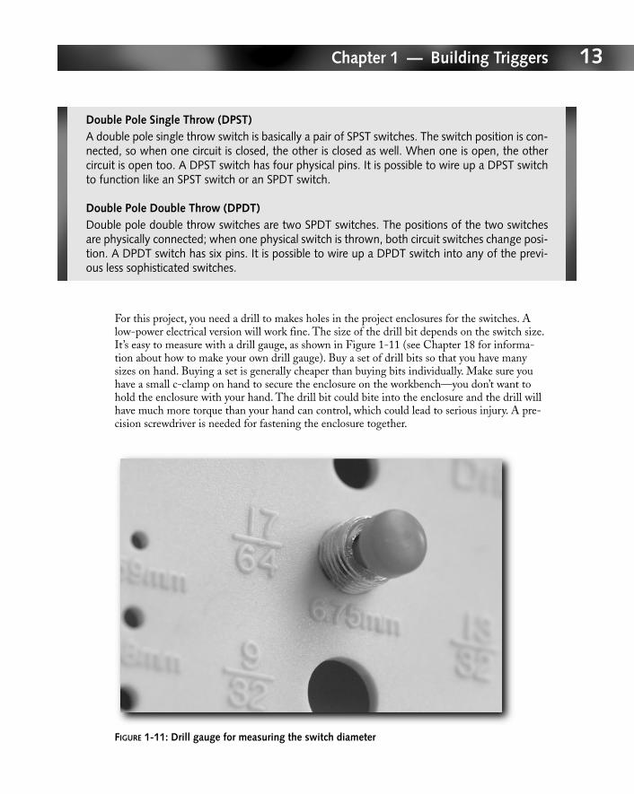
For this project, you need a drill to makes holes in the project enclosures for the switches. Alow-power electrical version will work fine. The size of the drill bit depends on the switch size.It’s easy to measure with a drill gauge, as shown in Figure 1-11 (see Chapter 18 for informa-tion about how to make your own drill gauge). Buy a set of drill bits so that you have manysizes on hand. Buying a set is generally cheaper than buying bits individually. Make sure youhave a small c-clamp on hand to secure the enclosure on the workbench—you don’t want tohold the enclosure with your hand. The drill bit could bite into the enclosure and the drill willhave much more torque than your hand can control, which could lead to serious injury. A pre-cision screwdriver is needed for fastening the enclosure together.
FIGURE 1-11: Drill gauge for measuring the switch diameter
Double Pole Single Throw (DPST)A double pole single throw switch is basically a pair of SPST switches. The switch position is con-nected, so when one circuit is closed, the other is closed as well. When one is open, the othercircuit is open too. A DPST switch has four physical pins. It is possible to wire up a DPST switchto function like an SPST switch or an SPDT switch.
Double Pole Double Throw (DPDT)Double pole double throw switches are two SPDT switches. The positions of the two switchesare physically connected; when one physical switch is thrown, both circuit switches change posi-tion. A DPDT switch has six pins. It is possible to wire up a DPDT switch into any of the previ-ous less sophisticated switches.
05_596519_ch01.qxd 8/19/05 12:34 PM Page 13
14 Part I — Hacking Cameras
When you are ready to put all the electrical connections together, you need a wire stripper tostrip the insulation from the end of the wires. A wire stripper costs a few bucks at the localhome improvement store. The soldering iron and solder help you create good electrical contactsbetween the switch contacts and the wires (see Appendix A for a quick guide to the basics ofsoldering). You can find soldering irons and solder at Radio Shack.
Drilling the CaseThe first step in making your own remote trigger is to drill the project enclosure. Before youdo so, use the drill gauge to measure the hole required by the switch. Poke the switch throughthe holes in the gauge until you find the right size. Then mount the right sized drill bit ontothe drill.
Before actually starting to drill, use the c-clamp to secure the project box onto the workbench(see Figure 1-12). My workbench has several holes over the surface for drill bits to drillthrough. If your workbench doesn’t have the same facility and you don’t want accidentally todrill into it, I suggest you place a block of wood between the project box and the workbench.With a wood block in between, when you drill through the project box, you’ll drill into thewood block instead of your workbench.
FIGURE 1-12: The project box is secured onto the workbench
05_596519_ch01.qxd 8/19/05 12:34 PM Page 14
15Chapter 1 — Building Triggers
After drilling all of the holes for your enclosure, test fit each jack and switch in the enclosure.This step is your chance to make sure the project box is drilled to your satisfaction, so you canmake any additional modification as needed.
Soldering the WiresWhen you are done drilling the enclosure, you can start soldering the parts together. Wire upthe switches based on the conceptual circuit diagrams presented in the “How Does a RemoteTrigger Work?” section. When you are ready to solder the interface jack, refer to the “CanonE3 Connector” sidebar for an overview and solder the connection to match the pin-out. Followthe instructions in Appendix A if your soldering skills are rusty.
After you have soldered all of the wires and contacts, you should test out your trigger beforeactually fitting everything together. No matter how confident you are about your result, youmay find that the trigger is defective. I don’t know how many times I put something together,whether it’s an electrical project or an internal computer component upgrade, thinking it’s per-fect, but after tightening the last screw, it fails to work. So, before all the switches and wires andthe jack are in the project box, plug it into your camera. Verify that all the switches are workingas expected. If everything works properly, you can move to the next step. Otherwise, pull outyour digital multimeter (see Figure 1-13) and test all of the connections.
FIGURE 1-13: A digital multimeter
05_596519_ch01.qxd 8/19/05 12:34 PM Page 15
16 Part I — Hacking Cameras
Canon N3 Connector
The Canon N3 shutter release trigger connector, found on higher-end Canon EOS cameras, hasthree connector pins. The male connector is designed onto the camera body, while the femaleconnector is designed for shutter release trigger accessories. Unlike the E3 connector (refer tothe “Canon E3 Connector” sidebar), which is a standard 2.5mm sub-mini connector used in theaudio world, the N3 connector, shown in Figure 1-14, is proprietary, made by Canon. Neitherthe male nor the female connector can be sourced from anywhere. Your best bet is to buy anaccessory or cable adapter (such as the T3 to N3 adapter), and then cut the N3 heads off foryour project.
FIGURE 1-14: The N3 connector is the circular port on the right. The circular port on the left is a PC terminal for triggering flashes and strobes.
05_596519_ch01.qxd 8/19/05 12:34 PM Page 16
17Chapter 1 — Building Triggers
A digital multimeter is a multi-purpose electronic measurement tool. The digital multimeter canmeasure voltage, resistance, and current. Using the resistance mode, you can check for bad con-nections in your circuit.
Fitting the Pieces TogetherAfter you’ve successfully tested the circuits, you can carefully fit everything into your projectbox. You may have to bend the circuit wires to fit the box. Try to bend them at sleeved unsol-dered locations to prevent breaking the soldered contact points. Once everything is fitted intothe project case, use a #1 Phillips precision screwdriver to fasten the screw and the case coverstogether. At this point, you need to test your finished trigger once again. As careful as you wereputting the case together, it is possible for a fragile soldering contact to break loose. You don’twant to wait and find out that your remote trigger is not working when you are out in the field.
Making a Delay TriggerYou are probably already familiar with a delay trigger. You use one whenever you place yourdigital camera in front of a group of people, set the 10-second timer, and run into the sceneyourself. Or whenever you want to shoot a self-portrait, such as that shown in Figure 1-15.Most decent cameras on the market have pretty good built-in self-timers. It’s practically anindustry standard to set them to 10 seconds. There are two reasons you might want to make adelay trigger yourself: First, you can make one in case your camera doesn’t come with a self-timer; second, the built-in 10-second timer is either too short or too long for your needs.
I learned to build a delay trigger because I found through experience that the 10-second delaytimer is simply not long enough for me to set up a perfect shot. As my photographic experienceincreases over time, my taste for the “perfect” shot also increases. I found myself taking fromseveral minutes to several hours just to perfectly set up a scene and all the models. When I haveto join the scene myself, the setup time for each shot far exceeds the 10 second allowance.
The pin-out for the Canon N3 connector (looking at the N3 connector on the camera) is listedas follows:
■ Top - ground
■ Left - shutter
■ Right - focus
What this pin-out means is that if you short the right pin and the top pin, the camera focuses (inAF mode). If you short the left pin and top pin, the shutter releases.
05_596519_ch01.qxd 8/19/05 12:34 PM Page 17
18 Part I — Hacking Cameras
Just recently, I visited the Villa Riviera building in Long Beach, California, and I had a chanceto shoot some wonderful environmental portraits of my girlfriend and me. I had to set up myCanon EOS D30 digital SLR on the other side of the courtyard. For each shot, I set the 10-second timer, ran to the other side of the courtyard, and tried to pose before the timer went off.Each time I failed. After taking five unsuccessful frames, I finally gave up.
Without my further rambling, let’s start making a delay trigger.
FIGURE 1-15: A self-portrait using the 10-second timer delay
05_596519_ch01.qxd 8/19/05 12:34 PM Page 18
19Chapter 1 — Building Triggers
Parts You NeedHere are the parts you will need to complete this project:
� 555CN Timer IC (276-1723) or TLC555 Low-Power CMOS Timer (276-1718)
� 4.7K ohm 1/2W 5% Carbon Film Resistor (271-1124)
� 2200µF Electrolytic Capacitor
� 0.01µF Polyester Film Capacitor (272-1065)
� Heavy-duty 9V Battery Snap Connector (270-324)
� SPST Submini Slide Switch (275-409)
� Stereo 3⁄32" Submini Phone Jack (274-245)
� 6" Matching Solderless PC Board (276-170)
� Project case
� 9-volt battery
These are all fairly basic electronics parts, so they can be found easily at your favorite electron-ics store. I bought them all at Radio Shack, either locally or online. For your convenience, I havelisted their Radio Shack part numbers.
The 555 timer chip has been a popular integrated circuit (IC) ever since its invention (see the“555 Timer Chip” sidebar later in the chapter). All circuits that require some kind of timinghave this chip. Because of their popularity, there are tons of supplies from multiple manufactur-ers, which drives the cost down. Currently, they cost about a buck fifty each. Pick up a fewspares for circuit testing purposes. When you put your prototype together, it’s likely not goingto work correctly the first time. The extra chips can help you determine if it’s a bad chip or ifit’s your circuit at fault.
The SPDT Micromini Relay looks like a black block, which is not very elegant. Its operationis also not elegant—it emits loud clicking noises. The noise is good for testing, but in normaloperation, it can get annoying. I had originally wanted to use the SPST Reed Relay (275-233),which has a fast response, a compact size, and a lower cost. And best of all, no loud clicks!Unfortunately, the reed relay is simply an open/close circuit switch, whereas the MicrominiRelay is a two-position switch. Because the 555 timer defaults to a signal high during count-down, a simple open/close switch wouldn’t have worked without a more complex circuit. Forthe purpose of learning, you wire up the two-position relay in reverse, or negative, logic towork as a delay trigger.
05_596519_ch01.qxd 8/19/05 12:34 PM Page 19
20 Part I — Hacking Cameras
A relay was chosen as the trigger mechanism because it enables circuit independence. Thus, theswitch is on the camera’s circuit, independent of the timer circuit you create. This independenceensures that the circuit works with most, if not all, cameras. Using an independent circuit alsomeans that you won’t ever fry your camera’s circuitry with your timer circuit.
The 555 timer circuit changes state on a circuit open rather than a circuit closed signal.Therefore, you use an interesting normally closed pushbutton switch in this project, because thenormally closed pushbutton keeps the circuit energized all the time, preventing the 555 timerfrom changing states. When you push the button, it breaks the circuit, causing the chip tochange state and the timer to start.
The resistor and the first capacitor in the list are the components that will control the timedelay. See the “Circuit Diagram” section later in the chapter for a more detailed description.
Resistors are available in limited values. The resistor value you need may not be available off theshelf. Instead, you can make different resistor values by combining multiple resistors in series andin parallel. When resistors are connected in series, add up the resistor values to obtain the totalresistor value. For parallel resistors, add up the reciprocals of the resistance values, and then takethe reciprocal of the total to calculate the total resistor value.
The heavy-duty 9-volt battery connector is very useful for connecting a battery source to yourproject. It can be used with a 9-volt battery or with a battery holder from Radio Shack. TheRadio Shack AA battery holders are available in a variety of configurations that can hold fromone AA battery to eight AA batteries. Each battery holder has a 9-volt battery connector sothat it can be connected to your project.
The slide switch is used to turn the circuit on and off. The sub-mini phone jack is used to con-nect to your camera. Your finalized circuit is transferred to the solderless PC board. Althoughit is described as solderless, you actually solder parts onto this circuit board. A 9-volt batterypowers the timing circuit.
The following list includes additional parts you’ll want to pick up. Although they will not makeit into your finalized circuit, they are necessary for prototyping and testing. Without them, youmight spend a lot of time putting a circuit together that doesn’t work.
� 5mm yellow LED (276-021)
� 100 ohm 1/4W 5% Carbon Film Resistor 5-pack (271-1311)
� AA Battery Holder (270-383)
� 4 AA batteries
The yellow LED is a visual indicator for you to see if your circuit works. In this project it simulates the camera trigger visually. Without this indicator, you would be in the dark aboutwhether the timing circuit works or not. The resistors work with the LED and provide the nec-essary current-limit to prevent the LED from burning out. See the “Make Your Own InfraredEmitter” sidebar in Chapter 16 for more information on the lack of LED resistance. The AAbattery holder and the four AA batteries power the LED.
05_596519_ch01.qxd 8/19/05 12:34 PM Page 20
21Chapter 1 — Building Triggers
555 Timer Chip
The 555 timer chip is one of the most useful integrated circuits (IC) in existence. Introduced inthe 1970s as the IC Time Machine, it provided circuit designers and hobbyists with an inexpen-sive commercial electronic timer. Today, 555 timer chips are available from many manufacturersand are readily available at your local electronic store. Information about the 555 timer chip isalso widely available on the Internet. My favorite is the National Semiconductor LM555 Timerspecification sheet that is downloadable at www.national.com/ds/LM/LM555.pdf.
555 timer chips are available in a bipolar and a CMOS version (see Figure 1-16). The CMOS ver-sion is typically rated to operate from 3 to 18 volts. The bipolar version operates from 4.5 to 16volts. The bipolar version also requires more current than the CMOS version, which makes theCMOS timer chips the perfect candidate for low power to very low power applications. On theother hand, the bipolar chip can handle considerably greater current for high-power applications.
FIGURE 1-16: A bipolar timer chip and a CMOS timer chip look identical. The only way you can tell a difference is by reading their packaging and specification sheet.
Continued
05_596519_ch01.qxd 8/19/05 12:34 PM Page 21
22 Part I — Hacking Cameras
Tools You NeedHere are the tools you will need to complete this project:
� Breadboard (276-174)
� Solderless Breadboard Jumper Wire Kit (276-173)
� Digital multimeter
� Needle-nose pliers
� Soldering iron
� 0.032" diameter 60/40 Standard Rosin-Core Solder (64-009E)
The breadboard is a piece of white plastic with a lot of tiny square holes (see Figure 1-17).These holes allow you to insert electrical wire and component leads. The holes are connectedvia different patterns of rows and columns. Figure 1-18 shows the connection pattern. Thebreadboard is an essential part for prototyping and testing your design.
When working with breadboards, a pair of needle-nose pliers is a must. You really want to usethe small type with a long nose. This tool helps you insert wire leads and component leads intothe breadboard sockets.
Circuit DiagramThe delay timer circuit is shown in Figure 1-19. It is a fairly simple circuit that is based entirelyon the monostable operation shown in the LM555 specification sheet (refer to the “555 TimerChip” sidebar). The circuit is unchanged, but a few minor components have been added. A bat-tery was added to the circuit to power the timer chip. A switch was added to turn the circuit onand off. A normally closed pushbutton switch was added to start the timer. A relay was addedto provide independent triggering of the camera through the timer circuit. And a camera wasadded to show how to interface the circuit to the camera.
Continued
The 555 timer chip has limitations on the values that can be used for R1, R2, and C (see circuitdiagrams). The resistor values cannot be less than about 1 kilo-ohm and should not be greaterthan about 1 mega-ohm. A resistor with resistance less than 1 kilo-ohm results in excessive cur-rents in the circuit, while a resistor greater than 1 mega-ohm does not pass enough currentthrough the circuit. Capacitor values should be between 100 pF and about 10µF. If you followthese rules, the slowest pulses that can be accurately produced have a frequency of around 1pulse every 10 seconds (0.1 Hz).
The packaging of the 555CN Timer IC (276-1723) mentions “Times microseconds throughhours.” I suspect that the newer 555 IC design has done away with resistor and capacitor valuerestrictions.
05_596519_ch01.qxd 8/19/05 12:34 PM Page 22
23Chapter 1 — Building Triggers
FIGURE 1-17: A breadboard
FIGURE 1-18: The bottom of the breadboard shows the electrical connections. When you buya breadboard, a label covers the bottom to insulate the metal contacts from other potentialelectrical contacts. I pulled the label off my breadboard to show you the pattern underneath.
05_596519_ch01.qxd 8/19/05 12:34 PM Page 23
24 Part I — Hacking Cameras
FIGURE 1-19: The delay timer circuit
Some resources have mentioned that the 0.01µF capacitor may not be needed with a CMOStimer chip. Based on my experience, the capacitor is required for both the bipolar and CMOStimer chips. Without it, the bipolar chip does not work at all, and the CMOS chip becomesextremely speedy. I have noticed a ten-fold speed-up in frequency.
By changing R1 and C, you can vary the trigger timing. The delay time is calculated by the fol-lowing formula:
T = 1.1 × R1 × C
T is in seconds, R1 is in ohms, and C is in farads. With the 4700 ohms resistor and the 2200µFcapacitor picked for this project, the timer delays 11.37 seconds before triggering the camera.
555Timing
chip
1
2
3
4
8
R1
C
0.01 µF
7
6
5
05_596519_ch01.qxd 8/19/05 12:34 PM Page 24
25Chapter 1 — Building Triggers
If you read the “555 Timer Circuit” sidebar, you are probably wondering how I got away withusing a 2200µF capacitor. My experience has shown that although timing isn’t truly accurate byviolating the rules, the 555 timer chip still works. And it still produces a frequency on par with thecalculation. For camera triggering, I wouldn’t worry so much about accuracy or precision. But ifyou really need an extremely accurate and precise timer, you need to design a more complicatedcircuit with all the right parts.
I picked the SPDT Micromini 5VDC Relay because of its double throw characteristic (refer tothe “Switch Terminology” sidebar). The 555 timer chip outputs high during the delay and out-puts low when the delay elapses. That is exactly the opposite of what you want. You want thecircuit to output high after the delay elapses. A simple single throw relay would not work.Fortunately you can emulate that characteristic by wiring up a double throw relay, as shownin Figure 1-20.
FIGURE 1-20: The SPDT Micromini 5VDC Relay circuit
This delay timer is a very basic circuit that gets the job done, but it doesn’t do it particularlywell, especially considering that the trigger is on until the normally closed button is pressed.But the knowledge you gained by building this circuit can start you thinking, and later you canbuild more advanced and elegant timing circuits.
To timer circuit
Resistor Color Code
Resistor values are color coded onto the resistor bodies. There are generally three to four bandson each resistor. From the resistor end where the band is closer to the lead, the first color bandsignifies the first digit in the resistor value. The second color band represents the second digit inthe resistor value. The third color band indicates a multiplier for the two digits. The fourth band(if it exists) determines the tolerance defined by the manufacturer for that particular resistor. Thepossible values for each band are shown in Table 1-1.
05_596519_ch01.qxd 8/19/05 12:34 PM Page 25
26 Part I — Hacking Cameras
Table 1-1: Resistor Band Color Chart
First and Second Color Band Third Color Band Fourth Color Band
Band Color Value Band Color Multiplier or Band Color ToleranceDivisor Value
Black 0 Black ×1 Gold 5% 5%
Brown 1 Brown ×10 Silver 10% 10%
Red 2 Red ×100 None 20% 20%
Orange 3 Orange ×1,000
Yellow 4 Yellow ×10,000
Green 5 Green ×100,000
Blue 6 Blue ×1,000,000
Violet 7 Silver ÷100
Gray 8 Gold ÷10
White 9
Prototyping the CircuitWith the circuit worked out, your first task is to prototype the circuit on a breadboard. Typically,I like to use the top row as the positive power source and use the bottom row as the negativeground. These two rows are linked across the entire breadboard, making them easy to access forthe rest of the circuits.
The first thing you should do is find a nice spot in the middle of the breadboard for yourtimer chip. It needs to be inserted horizontally with the pins above and below the trench (seeFigure 1-21). This gives each pin its own contact strip and keeps the pins from shorting eachother.
Use a chip puller to remove ICs from the breadboard or chip sockets, or use a screwdriver to prythem off. Pulling them off with your fingers forcefully could be dangerous. I’ve had their tinylegs embedded in my flesh before.
Now wire up the rest of the circuit using jump wires, and attach electronic components asneeded. The needle-nose pliers will do wonders on the breadboard compared to your fingers.When working with tiny electronic components, your fingers are big columns from a Greektemple. Use the needle-nose pliers to thread the jumper wires and leads on the prototype cir-cuit. When you are done wiring everything, you’ll see a circuit that looks like Figure 1-22.
05_596519_ch01.qxd 8/19/05 12:34 PM Page 26
27Chapter 1 — Building Triggers
FIGURE 1-21: The timer chip inserted in the breadboard
FIGURE 1-22: The delay timer prototyped on a breadboard
05_596519_ch01.qxd 8/19/05 12:34 PM Page 27
28 Part I — Hacking Cameras
At this point, you are probably pretty excited about the circuit you just put together. It’s timeto insert the testing circuit. In place of the camera, wire up the AA battery holder, the resistor,and the LED in series (see Figure 1-23). This series of electrical components will give you avisual indicator of the trigger mechanism. Plug in a 9-volt battery to power the timing circuitand insert four AA batteries to power the LED.
FIGURE 1-23: The breadboard with the testing circuit installed
Once wired, the LED stays on. This is normal because you have wired the relay in reverse.This is also the non-elegant portion of the design that I mentioned earlier. When you push thebutton, the LED should turn off. You’ll hear the relay click. The LED will stay off for 11.37seconds. Then it will turn back on again. The turning on is what causes the camera to triggerwhen you finally wire it to your camera.
Because this circuit is not elegant, you will have to set your camera to one-shot mode.Otherwise, when the light turns on and stays on, the camera will continue to fire off pictures.
Soldering the WiresA breadboard circuit is perfect for prototyping and testing. But it’s easy for the circuit to getscrewed-up because a lead comes loose. After you have tested the prototype circuit, you canmemorialize your design by soldering everything to a PC board. I have found that Radio Shackhas made a 6" Matching Solderless PC Board (276-170) that is perfect for this purpose. ThisPC board matches the breadboard exactly so that you don’t even have to rewire your circuit for
05_596519_ch01.qxd 8/19/05 12:34 PM Page 28
29Chapter 1 — Building Triggers
the PC board. Simply transfer all of the wires and components from the breadboard to this PCboard and you’re done.
Just make sure you test your finalized circuit again with the visual indicator. It’s easy to makemistakes even if you are just transferring the circuit from one medium to another. And therecould be bad solder connections.
Putting It TogetherOnce you are happy that the circuit is working correctly on the new PC board, mount it into aproject case. The project case helps prevent damage to the components on the circuit board.(And if you drop it, parts won’t scatter all over the floor.)
Making an Interval TriggerIn this section you use the 555 timer chip to make an interval trigger. The interval trigger is farmore interesting than the delay trigger because it can help you document the changing envi-ronment around you. You can take sequential pictures of flowers that bloom in one night. Youcan shoot a sequence of changing cloud formations. Or you can shoot the motion of the stars.
Most camera manufacturers make interval triggers for their high-end SLRs. For example,Canon makes a TC80N3 Timer Remote Control for EOS cameras that has an N3 connector(refer to the “Canon N3 Connector” sidebar). Because the lower-end EOS Rebel-series ofcameras uses the E3 connector (refer to the “Canon E3 Connector” sidebar), the Rebel-seriescameras can’t connect to the TC80N3 Timer Remote Control. But you can make an intervaltimer yourself.
Resistor Characteristics
Metal Foil: Low tolerance. Very low temperature coefficients. Long stability.
Metal film: Low tolerance (nominally 0.1 to 1 percent). Low temperature coefficients. Long sta-bility. Thin film is more stable from temperature changes than thick film.
Carbon film: High temperature coefficient. Tolerance nominally 2 to 10 percent.
Carbon: Very high temperature coefficient.
Composition: Tolerance nominally 5 to 20 percent. Tolerance becomes higher over time throughaging and humidity.
Because resistors can change characteristics over time, you can place a variable resistor in serieswith a fixed resistor for precise timing applications. The variable resistor can be adjusted and cal-ibrated for different conditions.
05_596519_ch01.qxd 8/19/05 12:34 PM Page 29
30 Part I — Hacking Cameras
The delay trigger in the previous section is the cornerstone to understanding the capability ofthe 555 timer chip. Therefore, a lot of tips and notes in the previous section apply to the inter-val trigger as well. For the interval trigger, I will present only pertinent information that differsfrom the previous section. Unless you are already extremely familiar with the 555 timer chip, Isuggest that you thoroughly review the previous section.
Parts You NeedHere are the parts you will need to complete this project:
� 555CN Timer IC (276-1723) or TLC555 Low-Power CMOS Timer (276-1718)
� SPDT Micromini 5VDC Relay (275-240)
� 4.7K ohm 1/2W 5% Carbon Film Resistor (271-1124)
� 100 ohm 1/4W 5% Carbon Film Resistor 5-pack (271-1311)
� 0.01µF Polyester Film Capacitor (272-1065)
� 4700µF Electrolytic Capacitor (272-1022)
� SPST Submini Slide Switch (275-409)
� Stereo 3⁄32" Submini Phone Jack (274-245)
� Heavy-duty 9V Battery Snap Connector (270-324)
� 9-volt battery
Capacitor Characteristics
Capacitors come in different types. Each type has different characteristics appropriate for differ-ent applications. Some capacitors have a lower tolerance and are good for accurate and precisetiming applications. Others are more tolerant and thus less accurate and precise. In most cases,timing doesn’t need to be overly accurate and precise for general-purpose camera triggering.Of course, if you are building a mission-critical camera trigger, stick with the best parts.
Metal film: Film capacitors include polycarbonate, polystyrene, polyester, and polypropylene.All of these film types are excellent for timing applications.
Tantalum: Tantalum capacitors have high dielectric absorption characteristics and high leakage.Therefore they are not suitable for timing applications. Use them only for non-critical situations.
Electrolytic: Electrolytic capacitors suffer from loose tolerances, poor stability, and high leakage.They are also not suitable for critical timing applications.
Ceramic: Ceramic capacitors are highly unstable and should also be avoided for timing applications.
05_596519_ch01.qxd 8/19/05 12:34 PM Page 30
31Chapter 1 — Building Triggers
Refer to the section “Making a Delay Trigger” for information on these parts.
The following parts are used for testing the prototype:
� 5mm yellow LED (276-021)
� AA Battery Holder (270-383)
� 4 AA batteries
Tools You NeedHere are the tools you will need to complete this project:
� Breadboard (276-175)
� Solderless Breadboard Jumper Wire Kit (276-173)
� Needle-nose pliers
� Digital multimeter
� Soldering iron
� 0.032" diameter 60/40 Standard Rosin-Core Solder (64-009E)
The tools listed basically mirror the tool list from the “Making a Delay Trigger” section, so Iwon’t go into further detail here.
Circuit DiagramThe interval timer circuit is shown in Figure 1-24. It is a fairly simple circuit based entirely onthe astable operation shown in the LM555 specification sheet (refer to the “555 Timer Chip”sidebar). The circuit was unchanged, but a few minor components were added. A battery wasadded to the circuit to power the timer chip, a switch was added to turn the circuit on and off, arelay was added to provide independent triggering of the camera through the timer circuit, anda camera was added to show how to connect the circuit to the camera.
By changing R1, R2, and C, you can vary the interval and trigger timing. The interval timing isthe delay between each trigger. For overnight exposure, depending on how many images youwant to capture, you can set it from seconds to minutes to hours. The interval time is calculatedby the following formula:
T1 = 0.693 × (R1 + R2) × C
05_596519_ch01.qxd 8/19/05 12:34 PM Page 31
32 Part I — Hacking Cameras
FIGURE 1-24: The interval trigger circuit diagram
The triggering timing determines how long to hold the camera button down. This could rangefrom a few milliseconds to a second or two, depending on the camera. I usually set it to 1 sec-ond just to be safe. The trigger timing is calculated by the following formula:
T2 = 0.693 × R2 × C
T1 and T2 are in seconds, R1 and R2 are in ohms, and C is in farads. For my project, I set R1to 18800 ohms (four 4700 ohms resistors wired in series), R2 to 300 ohms (three 100 ohmsresistors wired in series), and C to 4700µF. With these values, the interval of the timer is62.210 seconds and the trigger time is 0.977 seconds. These values are close enough to 1-minute intervals and holding the camera trigger down for 1 second.
To put the interval trigger together, follow the steps from the sections “Prototyping theCircuit,” “Soldering the Wires,” and “Putting It Together.”
You’ll need to refer to the “Making a Delay Trigger” section when you wire up the interval trig-ger (see Figure 1-25). Remember to test your circuit with the LED, as shown in Figure 1-26.
555Timing
chip
1
2
3
4
8
R1
C0.01 µF
7
6
5R2
05_596519_ch01.qxd 8/19/05 12:34 PM Page 32
33Chapter 1 — Building Triggers
FIGURE 1-25: The delay timer prototyped on a breadboard
FIGURE 1-26: The breadboard with the testing circuit installed
05_596519_ch01.qxd 8/19/05 12:35 PM Page 33
34 Part I — Hacking Cameras
Connecting the Triggers to a Point-and-Shoot CameraAs you learn in the rest of this chapter, it’s fairly easy to connect your trigger to an SLRbecause SLRs already have trigger ports—you just have to build adapters to make the connec-tion work. But most P&S cameras do not come with any trigger ports at all. Fortunately, it ispossible to modify most P&S cameras so that you can connect any wired triggers you build.On most P&S cameras, the shutter button is simply a circuit closure switch, so it is a straight-forward task to wire a trigger interface to the button circuit.
In this section I demonstrate how to interface to the shutter button on my Sony DSC-P92digital camera. The modification will be presented on a conceptual level so that you can applyit to any P&S camera.
Chapter 16 covers in detail how to take the Sony DSC-P92 case apart, so refer to that chapterbefore getting started.
Parts You NeedHere are the parts you will need to complete this project:
� 3⁄32" Submini Phone Jack (274-245)
� Wires
The 3⁄32" (2.5mm) sub-mini phone jack is the standard trigger port on the entry-level CanonEOS SLRs. The earlier projects in this chapter use this interface because it is common andeasy to find the parts. In this project you again use this connector.
Tools You NeedHere are the tools you will need to complete this project:
� #1 Phillips precision screwdriver
� Digital multimeter
� Soldering iron
� 0.032" diameter 60/40 Standard Rosin-Core Solder (64-009E)
� Drill
� Drill bit
� Drill gauge
05_596519_ch01.qxd 8/19/05 12:35 PM Page 34
35Chapter 1 — Building Triggers
The Sony DSC-P92 case has four tiny machine screws that must be unfastened with your #1Phillips precision screwdriver. After getting inside the camera and finding the shutter button’swire and connector, you use the digital multimeter to determine the pin-out. Then you use thesoldering iron and solder to add your own trigger port.
Taking the Camera ApartFollow the instructions presented in Chapter 16 to take apart the Sony DSC-P92. If you areworking with another camera, take care to find all the screws you need to remove. When youtake the case apart, make sure you do so slowly and avoid breaking any ribbon cables. Surfacemount ribbon cables in today’s digital camera are nearly impossible to fix at home.
1. After taking the back cover off, remove the ribbon cable connector that links the backcover and the circuit board (see Figure 1-27).
FIGURE 1-27: The ribbon cable connectors on the bottom of the Sony DSC-P92
05_596519_ch01.qxd 8/19/05 12:35 PM Page 35
36 Part I — Hacking Cameras
2. Notice that there is another smaller ribbon cable connector. Remove that as well, usingeither a small flat blade screwdriver or your fingernails.
3. Next, look at the top of the digital camera, where the power button and the shutter but-ton are located (see Figure 1-28). Note that two tabs are securing the circuit board in thepicture—one tab is above the shutter button and the other to the left.
FIGURE 1-28: Two tabs are around the shutter button.
4. Pull those tabs slightly, and the circuit board will come loose.
5. With the circuit board freed from the tabs, separate the circuit board and camera inter-nals from the front cover as shown in Figure 1-29.
05_596519_ch01.qxd 8/19/05 12:35 PM Page 36
37Chapter 1 — Building Triggers
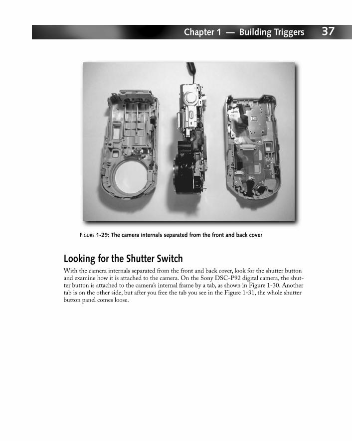
FIGURE 1-29: The camera internals separated from the front and back cover
Looking for the Shutter SwitchWith the camera internals separated from the front and back cover, look for the shutter buttonand examine how it is attached to the camera. On the Sony DSC-P92 digital camera, the shut-ter button is attached to the camera’s internal frame by a tab, as shown in Figure 1-30. Anothertab is on the other side, but after you free the tab you see in the Figure 1-31, the whole shutterbutton panel comes loose.
05_596519_ch01.qxd 8/19/05 12:35 PM Page 37
38 Part I — Hacking Cameras
FIGURE 1-30: The shutter button panel is held to the camera internal by two tabs. One tab isshown in this picture; the second tab is on the other side.
Free the tab to remove the shutter button panel, as shown in Figure 1-31. Don’t pull it off justyet because the panel is attached to the circuit board by an orange ribbon cable to the left. Ifyou pull the panel off hastily, you might break that cable, and it is nearly impossible to repair.
Note also in Figure 1-31 that the flash capacitor is beneath the shutter button panel. It is stillcharged with very high voltage. Notice that the capacitor leads are on the right, protrudingfrom the circuit board. Don’t touch them or you might get a nasty surprise. I did accidentallytouch both pins with my right thumb once. It gave my thumb a little shock that felt like anumbing vibration.
Use electrical tape to cover the two leads while you are working on the camera to prevent acci-dental electrical shock.
05_596519_ch01.qxd 8/19/05 12:35 PM Page 38
39Chapter 1 — Building Triggers
FIGURE 1-31: The shutter button panel freed to reveal the flash capacitor
Shown from the other side, the ribbon cable connector looks like Figure 1-32. Use a small flat-head screwdriver or your fingernails to pry the ribbon cable connector loose and detach theshutter button panel.
Determining the Shutter Button PinsFigure 1-33 shows the shutter button panel detached from the camera. The ribbon cable issticking out on the bottom left. The orange portion of the ribbon cable is the insulated section,while the silver leads are actually electrical contacts. The power button has one position, andthe shutter button has two positions. So altogether there are three switches on this buttonpanel, which matches the number of electrical contacts as well—considering that each switchrequires two wires.
05_596519_ch01.qxd 8/19/05 12:35 PM Page 39
40 Part I — Hacking Cameras
FIGURE 1-32: The shutter button panel and its ribbon cable connector
You need to use a digital multimeter to determine which electrical contacts are associated witheach button. You need a friend for this task—one of you probes the electrical contacts, whilethe other person pushes down one of the buttons. Turn the digital multimeter on and set it upto measure resistance (ohms). Press and hold one of the buttons. Make sure you test each of thetwo positions on the shutter button separately.
Place the positive and negative test leads on two different electrical contacts. Try differentcombinations of electrical contacts until you see zero resistance (a closed circuit). The two con-tacts that showed the zero resistance are the right contacts for the button that was pressed. Onthe Sony DSC-P92 digital camera, the shutter button is associated with the third and fifthcontacts (counting from the left in Figure 1-33).
Soldering the Trigger InterfaceAfter you have determined the pins for different button functions, you need to solder the2.5mm (3⁄32") stereo jack to the pins. The best way is to first solder thin wires onto the pins,and then solder the wires to the stereo jack. Because the contact pins are extremely small andthin, soldering wires to it is a multi-step process. Start by heating the contact pin. Then flowa tiny bulb of solder onto the contact pin. Be careful that you don’t heat the adjacent pins orshort them out by flowing solder onto them.
05_596519_ch01.qxd 8/19/05 12:35 PM Page 40
41Chapter 1 — Building Triggers
FIGURE 1-33: The button panel is detached from the camera.
Next, tin the thin wire (see the instructions in Appendix A). Heat the thin wire and use it totransfer heat to the tiny bulb of solder. When both the soldering bulb and wire are heated, thesolder melts, flowing onto the thin wire. Remove the soldering iron. When the solder cools to asolid form, an electrical contact is made.
Use wires that are long enough for you to locate the stereo jack wherever you want on thecamera body. The following section discusses wire length in more detail.
Strip the other end of the wire. Insert the un-insulated wire end through the contact pin on the2.5mm stereo jack. Make sure the wire is connected to the correct pin (refer to the “Canon E3Connector” sidebar for the correct connection). Wrap the wire around so that it is temporarilysecured on the pin, as shown in Figure 1-34. While the wire is still secure on the pin, use thesoldering iron to apply heat to the wire and the contact pin at the same time. Place the end ofthe solder wire on the wire and the contact. When they get hot enough, the solder melts andflows onto both the wire and the contact. Remove the soldering iron. When the solder coolsdown, the connection is complete.
05_596519_ch01.qxd 8/19/05 12:35 PM Page 41
42 Part I — Hacking Cameras
FIGURE 1-34: The exposed wire wrapped on the contact pin
Perform this step for each of the Canon E3 connector functions: shutter trigger and auto-focus. If the camera doesn’t have auto-focus capability, you can ignore this step.
Modifying the Camera CaseIn this step, you want to mount the 2.5mm stereo jack on the camera itself, if possible. Theadvantages of mounting the trigger jack securely are, first, that it is convenient to access and,second, that there are no loose wires that could break as a result of wear and tear. But it’s notalways possible to mount the stereo jack on the camera. With today’s miniaturization of digitalcameras, the internal electronics are already crammed in a very small package. In this situation,where your camera is already crammed with parts, all you can do is drill a tiny hole for thewires to pass through and dangle the trigger port outside. Tie the wires into a knot on bothside of the hole to prevent excess wear and tear on the camera internals (see Figure 1-35).
You can also twist the wires together into a braid, as shown in Figure 1-36. When two wiresare braided together, the result is called a twisted-pair. The advantage is that when thewires are braided together, they become more durable.
05_596519_ch01.qxd 8/19/05 12:35 PM Page 42
43Chapter 1 — Building Triggers
FIGURE 1-35: Wires tied into a knot
05_596519_ch01.qxd 8/19/05 12:35 PM Page 43
44 Part I — Hacking Cameras
However, if you manage to find space to mount the stereo jack on your camera, make surethe jack still fits when a stereo plug is inserted into it. Once you’re satisfied that your plan willwork, use a drill gauge to determine the diameter of the stereo jack. Drill a hole in the cameracase just slightly bigger than the stereo jack. The stereo jack is secured from the outside with abolt. Make sure you don’t drill a hole that is bigger than the bolt. After drilling the hole, insertthe stereo jack through the hole from inside the camera body. Secure it with the bolt from theoutside, as shown in Figure 1-36.
FIGURE 1-36: Secure the stereo jack with the bolt supplied. In this picture, the stereo jack was secured to the drill gauge. But the idea applies to the camera body as well.
Reassembling the CameraWhen you reassemble the camera, route the wires around so they won’t be crushed. Crushedwires have the potential to deteriorate and short out over time. Route them so they won’t getcaught and interfere with the camera’s operation. Put the camera back together in the reverseorder used to take it apart. Don’t forget to plug in all the ribbon cables that you unplugged.
Extending the Remote SwitchThe wired remote trigger switches you can buy from the manufacturers have a fairly short wire.It might be anywhere from three feet to, at most, six feet long. And unless you had a particularneed in mind when you built your own trigger switch, you probably built one with a fairly shortcable as well.
05_596519_ch01.qxd 8/19/05 12:35 PM Page 44
45Chapter 1 — Building Triggers
Sometimes you’ll wish the trigger switch had a longer cable. You might want a longer cablebecause you want to shoot some self-portraits. Figure 1-37 is a self-portrait that I shot yearsago using a homemade extended cable. Running back and forth between the scene and thecamera can be extremely inconvenient, especially if the scene is far away. You might want toshoot wildlife. Some wild animals are very sensitive to the presence of humans. By setting upthe camera in a remote location, you won’t scare them away. Or you might want to take pic-tures of a hazardous environment, where your physical presence could be a danger to your life.It’s better to wire up a remotely triggered camera than to put your life in danger.
FIGURE 1-37: A self-portrait shot with an extended cable. Did you spot the cable? If I hadn’t pointed it out, you probably would have never noticed it.
05_596519_ch01.qxd 8/19/05 12:35 PM Page 45
46 Part I — Hacking Cameras
If you have followed the instructions in this chapter and built a remote trigger and interfacebased on the simple 2.5mm or 3.5mm stereo phone jack, you are in good shape. You can easilybuy 3.5mm stereo extension cables at Radio Shack or even build them yourself. Converters for2.5mm and 3.5mm stereo jacks are also readily available so you can easily convert them backand forth. Figure 1-38 shows these parts.
FIGURE 1-38: An extension cable, a 2.5mm to 3.5mm adapter, and a 3.5mm adapter to 2.5mm adapter
If you build your triggers using proprietary interfaces rather than a popular interface, I suggestyou build stereo adapter cables for your proprietary trigger. That way you will be able to buildyour extension from over-the-counter parts. Otherwise, you will always have to build customcables.