Built-In Self-Test for Built-In Self-Test for Field Programmable Field Programmable Gate Arrays Gate Arrays funded by National Security Agency funded by National Security Agency Chuck Stroud Chuck Stroud Electrical & Electrical & Computer Computer Engineering Engineering Auburn Auburn University University
Transcript
Built-In Self-Test for Built-In Self-Test for Field Programmable Gate ArraysField Programmable Gate Arrays
funded by National Security Agencyfunded by National Security Agency
• BIST for FPGAsBIST for FPGAs Logic resourcesLogic resources Routing resourcesRouting resources
• Demonstration of FPGA logic BIST & Demonstration of FPGA logic BIST & DiagnosisDiagnosis
The Need for TestThe Need for Test
2000 International Technology Roadmap for 2000 International Technology Roadmap for SemiconductorsSemiconductors (by the Semiconductor Industry (by the Semiconductor Industry Association - Association - SEMATECHSEMATECH) predicts by 2014:) predicts by 2014:
• Test machines will cost > $20MTest machines will cost > $20M• It will cost more to test a transistor than to It will cost more to test a transistor than to
manufacture itmanufacture it• Built-In Self-Test (BIST) is a likely solutionBuilt-In Self-Test (BIST) is a likely solution
Analog BIST is needed for mixed-signal systemsAnalog BIST is needed for mixed-signal systems Fault diagnosis is needed with BISTFault diagnosis is needed with BIST Tools are needed for automating BISTTools are needed for automating BIST
What is BIST?What is BIST?• Basic idea:Basic idea: Add circuitry to IC or PCB to facilitate Add circuitry to IC or PCB to facilitate
testing itselftesting itself Only power and clock needed during BIST sequenceOnly power and clock needed during BIST sequence Pass/Fail result reported at end of BIST sequencePass/Fail result reported at end of BIST sequence
No need for external test equipmentNo need for external test equipment
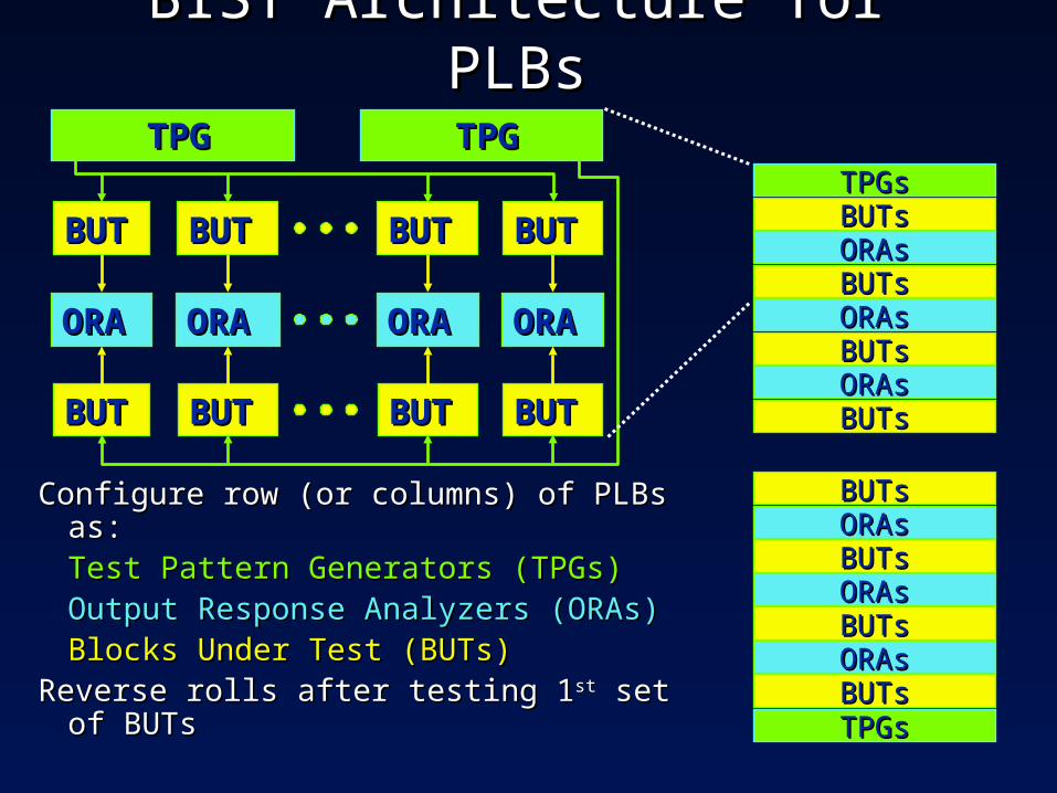
• Necessary components:Necessary components: Test Pattern Generator (TPG)Test Pattern Generator (TPG) Output Response Analyzer (ORA)Output Response Analyzer (ORA) For system level use:For system level use:
Test controllerTest controller Input isolationInput isolation
• Penalties:Penalties: area overhead, performance area overhead, performance• Benefits:Benefits: low testing time & cost low testing time & cost
break-point PIPs – connect/disconnect wire segmentsbreak-point PIPs – connect/disconnect wire segments To make long and short signal routesTo make long and short signal routes
multiplexer (MUX) PIPs select 1 of many wires for outputmultiplexer (MUX) PIPs select 1 of many wires for output Used at PLB inputsUsed at PLB inputs Primary interconnect media for new FPGAsPrimary interconnect media for new FPGAs
BIST for FPGAsBIST for FPGAs• Basic idea:Basic idea: reprogram FPGA to test itself reprogram FPGA to test itself• BIST logic disappears after testBIST logic disappears after test
No area overhead or performance penaltiesNo area overhead or performance penalties• Applicable to all levels of testingApplicable to all levels of testing
A generic test for a generic componentA generic test for a generic component Independent of system functionIndependent of system function
• Good diagnostic resolutionGood diagnostic resolution Logic:Logic: Look-Up Table (LUT) or flip-flop Look-Up Table (LUT) or flip-flop Routing:Routing: wire segment or switch wire segment or switch Reconfigure system function for fault-toleranceReconfigure system function for fault-tolerance
• CostCost: memory to store BIST configurations: memory to store BIST configurations
BIST Architecture for PLBsBIST Architecture for PLBs
Step 4:Step 4: Mark known faulty BUTs Mark known faulty BUTs
Step 5:Step 5: Look for inconsistences Look for inconsistences=>=> implies possible interconnect faultsimplies possible interconnect faults
Step 6:Step 6: If every PLB has been identified as If every PLB has been identified as fault-free or faulty, the group of faulty fault-free or faulty, the group of faulty PLBs has been uniquely diagnosedPLBs has been uniquely diagnosed
=>=> otherwise mark as unknownotherwise mark as unknown
Routing BIST ArchitectureRouting BIST Architecture• Wires Under Test (WUTs)Wires Under Test (WUTs)
Wire segments connected via PIPs & PLBs to form WUTsWire segments connected via PIPs & PLBs to form WUTs Opposite values on busses not under test (PIPs stuck-on)Opposite values on busses not under test (PIPs stuck-on) All WUTs are 2-tested to detect equivalent faultsAll WUTs are 2-tested to detect equivalent faults
• TPGs & ORAs formed as in logic BISTTPGs & ORAs formed as in logic BIST Exhaustive test patterns detect shorts, opens, & stuck-at faultsExhaustive test patterns detect shorts, opens, & stuck-at faults ORA compares two sets of WUTs (A WUTs & B WUTs)ORA compares two sets of WUTs (A WUTs & B WUTs)
Uses small Self-Test AReas (STARs) to test Uses small Self-Test AReas (STARs) to test routing resources routing resources
• Good diagnostic resolutionGood diagnostic resolution To STARTo STAR
• Higher speed testingHigher speed testing Fewer series PIPs delaysFewer series PIPs delays
Run STARs in parallelRun STARs in parallel• V-STARs test vertical routingV-STARs test vertical routing• H-STARs test horizontal routingH-STARs test horizontal routing
ORA TPGSTAR
ORA TPGSTAR
ORA TPGSTAR
ORA TPGSTAR
ORA TPGSTAR
Diagnostic ConfigurationsDiagnostic Configurations• Partition into smaller STARsPartition into smaller STARs
Identify faulty region of WUT Identify faulty region of WUT
TPGTPG
ORAORA
TPGTPG
ORAORA
TPGTPG
ORAORA
SingleSingle
wirewire
TPGTPG
ORAORA
TPGTPG
ORAORA
ORAORA
ORAORA
ORAORA
• Re-route portions of netRe-route portions of net Identify faulty wire segment or PIPIdentify faulty wire segment or PIP
• Add ORAs & change directionsAdd ORAs & change directions Identify fault region of WUTIdentify fault region of WUT
TPGTPG ORAORA ORAORA ORAORA
TPGTPGORAORAORAORAORAORA ORAORAORAORA
ORAORAORAORA
Test Results for Faulty FPGAsTest Results for Faulty FPGAsFailures from Chip 1Failures from Chip 1 At least 1 faultAt least 1 fault
maybe at intersection of STARsmaybe at intersection of STARs
11 33 55 77 99 1111 1313 1515 1717 1919
11
33
55
77
99
1111
1313
1515
1717
1919
V-STAR column positionV-STAR column position
H-S
TA
R r
ow
po
siti
on
H-S
TA
R r
ow
po
siti
on
11 33 55 77 99 1111 1313 1515 1717 1919
11
33
55
77
99
1111
1313
1515
1717
1919
H-S
TA
R r
ow
po
siti
on
H-S
TA
R r
ow
po
siti
on
V-STAR column positionV-STAR column position
Failures from Chip 2Failures from Chip 2 At least 2 faultsAt least 2 faults
maybe at intersection of STARsmaybe at intersection of STARsDiagnostic resultsDiagnostic results A short at row 10 column 8A short at row 10 column 8
Diagnostic resultsDiagnostic results A short at row 1 column 12A short at row 1 column 12 Short in 3 wires of 4-wire busShort in 3 wires of 4-wire bus
row 5 columns 6-8row 5 columns 6-8
110111010000100010110101System or BIST configSystem or BIST config
FPGAFPGA
Fault Injection EmulatorFault Injection Emulator• Faulty FPGA are difficult to findFaulty FPGA are difficult to find
1 FPGA with faulty PLB & 2 FPGAs with faulty routing1 FPGA with faulty PLB & 2 FPGAs with faulty routing
• We created a Fault Injection EmulatorWe created a Fault Injection Emulator Intercepts & modifies configuration bits prior to downloadIntercepts & modifies configuration bits prior to download Fault Emulator can create multiple faults in:Fault Emulator can create multiple faults in:
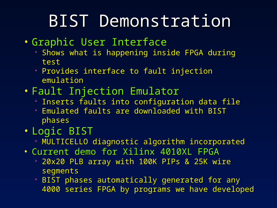
BIST DemonstrationBIST Demonstration• Graphic User InterfaceGraphic User Interface
Shows what is happening inside FPGA during testShows what is happening inside FPGA during test Provides interface to fault injection emulationProvides interface to fault injection emulation
• Fault Injection EmulatorFault Injection Emulator Inserts faults into configuration data fileInserts faults into configuration data file Emulated faults are downloaded with BIST phasesEmulated faults are downloaded with BIST phases
• Current demo for Xilinx 4010XL FPGACurrent demo for Xilinx 4010XL FPGA 20x20 PLB array with 100K PIPs & 25K wire segments20x20 PLB array with 100K PIPs & 25K wire segments BIST phases automatically generated for any 4000 BIST phases automatically generated for any 4000
series FPGA by programs we have developedseries FPGA by programs we have developed