Reference Manual Bulletin 1606 Switched Mode Power Supplies Catalog Number: 1606-XLP50E Index 1. Description ........................................................1 2. Specification Quick Reference ............................1 3. Catalog Numbers ................................................1 4. Certification Marks ..............................................1 5. AC-Input...............................................................4 6. Input Inrush Current Surge .................................5 7. DC-Input...............................................................5 8. Hold-up Time .......................................................6 9. DC-OK Output .....................................................6 10. Output .................................................................7 11. Efficiency and Power Losses................................8 12. Functional Diagram.............................................9 13. Reliability .............................................................9 14. Front Side and User Elements ...........................10 15. Terminals and Wiring........................................10 16. EMC ....................................................................11 17. Environment ......................................................12 18. Protection Features ...........................................12 19. Safety .................................................................13 20. Dielectric Strength ............................................13 21. Certifications .................................................... 14 22. Environmental Compliance ............................. 14 23. Physical Dimensions and Weight ..................... 15 24. Installation and Operation Instructions .......... 15 25. Accessory........................................................... 16 26. Application Notes ............................................. 17 26.1. Peak Current Capability ......................... 17 26.2. Back-feeding Loads ................................ 17 26.3. Series Operation ..................................... 18 26.4. Parallel Use to Increase Output Power . 18 26.5. Parallel Use for Redundancy .................. 18 26.6. Daisy Chaining of Outputs ..................... 19 26.7. Charging Batteries ............................. 19 26.8. External Input Protection....................... 20 26.9. Inductive and Capacitive Loads ............. 20 26.10. Operation on Two Phases ...................... 20 26.11. Use in a Tightly Sealed Enclosure .......... 20 26.12. Mounting Orientations .......................... 21 • PE and symbol—PE is the abbreviation for Protective Earth and has the same meaning as the symbol . • Earth, Ground—This document uses the term “earth” which is the same as the U.S. term “ground”. • T.b.d.—To be defined, value or description will follow later. • AC 230V—A figure displayed with the AC or DC before the value represents a nominal voltage with standard tolerances (usually ±15%) included. E.g.: DC 12V describes a 12V battery disregarding whether it is full (13.7V) or flat (10V) • 230Vac—A figure with the unit (Vac) at the end is a momentary figure without any additional tolerances included. • 50Hz vs. 60Hz—As long as not otherwise stated, AC100V and AC230V parameters are valid at 50Hz and AC120V parameters are valid at 60Hz mains frequency. • may—A key word indicating flexibility of choice with no implied preference. • shall—A key word indicating a mandatory requirement. • should—A key word indicating flexibility of choice Terminology and Abbreviations
Transcript
Reference Manual
Bulletin 1606 Switched Mode Power SuppliesCatalog Number: 1606-XLP50E
Index
1. Description ........................................................1 2. Specification Quick Reference ............................1 3. Catalog Numbers ................................................1 4. Certification Marks..............................................1 5. AC-Input...............................................................4 6. Input Inrush Current Surge.................................5 7. DC-Input...............................................................5 8. Hold-up Time.......................................................6 9. DC-OK Output .....................................................6 10. Output .................................................................7 11. Efficiency and Power Losses................................8 12. Functional Diagram.............................................9 13. Reliability .............................................................9 14. Front Side and User Elements...........................10 15. Terminals and Wiring........................................10 16. EMC....................................................................11 17. Environment ......................................................12 18. Protection Features ...........................................12 19. Safety .................................................................13 20. Dielectric Strength ............................................13
26.1. Peak Current Capability ......................... 17 26.2. Back-feeding Loads ................................ 17 26.3. Series Operation..................................... 18 26.4. Parallel Use to Increase Output Power . 18 26.5. Parallel Use for Redundancy.................. 18 26.6. Daisy Chaining of Outputs..................... 19 26.7. Charging Batteries ............................. 19 26.8. External Input Protection....................... 20 26.9. Inductive and Capacitive Loads ............. 20 26.10. Operation on Two Phases ...................... 20 26.11. Use in a Tightly Sealed Enclosure .......... 20 26.12. Mounting Orientations.......................... 21
• PE and symbol—PE is the abbreviation for Protective Earth and has the same meaning as the symbol .• Earth, Ground—This document uses the term “earth” which is the same as the U.S. term “ground”.• T.b.d.—To be defined, value or description will follow later.• AC 230V—A figure displayed with the AC or DC before the value represents a nominal voltage with standard tolerances (usually ±15%)
included. E.g.: DC 12V describes a 12V battery disregarding whether it is full (13.7V) or flat (10V)• 230Vac—A figure with the unit (Vac) at the end is a momentary figure without any additional tolerances included. • 50Hz vs. 60Hz—As long as not otherwise stated, AC100V and AC230V parameters are valid at 50Hz and AC120V parameters are valid at 60Hz
mains frequency.• may—A key word indicating flexibility of choice with no implied preference.• shall—A key word indicating a mandatory requirement.• should—A key word indicating flexibility of choice
Terminology and Abbreviations
All parameters are specified at 24V, 2.1A, 230Vac input, 25ªC ambient and after a 5 minutes run-in time unless noted otherwise.2 Rockwell Automation Publication 1606-RM034A-EN-P — March 2014
Bulletin 1606 Switched Mode Power Supplies
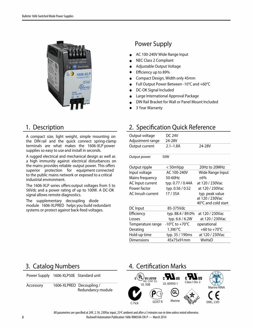
Power Supply AC 100-240V Wide Range Input NEC Class 2 Compliant Adjustable Output Voltage Efficiency up to 89% Compact Design, Width only 45mm Full Output Power Between -10°C and +60°C DC-OK Signal Included Large International Approval Package DIN Rail Bracket for Wall or Panel Mount Included 3 Year Warranty
1. Description 2. Specification Quick Reference Output voltage DC 24V Adjustment range 24-28V Output current 2.1–1.8A 24-28V Output power 50W Output ripple < 50mVpp 20Hz to 20MHz Input voltage AC 100-240V Wide Range Input Mains frequency 50-60Hz ±6% AC Input current typ. 0.77 / 0.44A at 120 / 230Vac Power factor typ. 0.56 / 0.52 at 120 / 230Vac AC Inrush current 17 / 35A typ. peak value
at 120 / 230Vac 40°C and cold start
DC Input 85-375Vdc Efficiency typ. 88.4 / 89.0% at 120 / 230Vac Losses typ. 6.6 / 6.2W at 120 / 230Vac Temperature range -10°C to +70°C operational Derating 1.3W/°C +60 to +70°C Hold-up time typ. 35 / 190ms at 120 / 230Vac Dimensions 45x75x91mm WxHxD
A compact size, light weight, simple mounting on the DIN rail and the quick connect spring-clamp terminals are what makes the 1606-XLP power supplies so easy to use and install in seconds. A rugged electrical and mechanical design as well as a high immunity against electrical disturbances on the mains provides reliable output power. This offers superior protection for equipment connected to the public mains network or exposed to a critical industrial environment.The 1606-XLP series offers output voltages from 5 to 56Vdc and a power rating of up to 100W. A DC-OK signal allows remote diagnostics. The supplementary decoupling diode module 1606-XLPRED helps you build redundant systems or protect against back-feed voltages.
3. Catalog Numbers 4. Certification Marks Power Supply 1606-XLP50E Standard unit
All parameters are specified at 24V, 2.1A, 230Vac input, 25ªC ambient and after a 5 minutes run-in time unless noted otherwise.Rockwell Automation Publication 1606-RM034A-EN-P — March 2014 3
Bulletin 1606 Switched Mode Power Supplies
Intended Use• This device is designed for installation in an enclosure and is intended for the general professional use such as in industrial control, office,
communication, and instrumentation equipment.• Do not use this power supply in aircraft, trains, nuclear equipment or similar systems where malfunction may cause severe personal injury or
threaten human life.
Installation Requirements• This device may only be installed and put into operation by qualified personnel.• This device does not contain serviceable parts. The tripping of an internal fuse is caused by an internal defect.• If damage or malfunction should occur during installation or operation, immediately turn power off and send unit to the factory for inspection.• Mount the unit on a DIN rail so that the terminals are located on the bottom of the unit. For other mounting orientations, refer to derating
requirements in this document.• This device is designed for convection cooling and does not require an external fan. Do not obstruct airflow and do not cover ventilation grid
(e.g. cable conduits) by more than 15%!• Keep the following installation clearances: 40mm on top, 20mm on the bottom, 5mm on the left and right sides are recommended when the
device is loaded permanently with more than 50% of the rated power. Increase this clearance to 15mm in case the adjacent device is a heat source (e.g. another power supply).
SHOCK HAZARD: Do not use the power supply without proper grounding (Protective Earth). Use the terminal on the input block for earth connection and not one of the screws on the housing.
- Turn power off before working on the device. Protect against inadvertent re-powering- Make sure that the wiring is correct by following all local and national codes- Do not modify or repair the unit- Do not open the unit as high voltages are present inside- Use caution to prevent any foreign objects from entering the housing- Do not use in wet locations or in areas where moisture or condensation can be expected- Do not touch during power-on, and immediately after power-off. Hot surfaces may cause burns.
WARNING: EXPLOSION HAZARDS! Substitution of components may impair suitability for this environment. Do not disconnect the unit or operate the voltage adjustment or S/P jumper unless power has been switched off or the area is known to be non-hazardous.
All parameters are specified at 24V, 2.1A, 230Vac input, 25ªC ambient and after a 5 minutes run-in time unless noted otherwise.4 Rockwell Automation Publication 1606-RM034A-EN-P — March 2014
Bulletin 1606 Switched Mode Power Supplies
5. AC-Input
AC input nom. AC 100-240V Wide-range input, TN-, TT-, IT-Mains, see Fig. 5-1 AC input range 85-264Vac Continuous operation 60-85Vac Full power for 200ms, no damage between 0 and 85Vac 264-300Vac < 0.5s Input frequency nom. 50 – 60Hz ±6% Turn-on voltage typ. 65Vac Steady-state value, see Fig. 5-1 Shut-down voltage typ. 55Vac Steady-state value, see Fig. 5-1
AC 100V AC 120V AC 230V Input current typ. 0.91A 0.77A 0.47A at 24V, 2.1A see Fig. 5-3. Power factor *) typ. 0.58 0.56 0.52 at 24V, 2.1A see Fig. 5-1. Crest factor **) typ. 3.05 3.26 3.91 at 24V, 2.1A Start-up delay typ. 32ms 32ms 32ms See Fig. 5-2. Rise time typ. 33ms 33ms 48ms 0mF, 24V, 2.1A, see Fig. 5-2. typ. 45ms 45ms 60ms 2mF, 24V, 2.1A, see Fig. 5-2. Turn-on overshoot max. 400mV 400mV 400mV See Fig. 5-2.
*) The power factor is the ratio of the true (or real) power to the apparent power in an AC circuit. **) The crest factor is the mathematical ratio of the peak value to RMS value of the input current waveform
Fig. 5-1 Input voltage range Fig. 5-2 Turn-on behavior, definitions
Turn
-on
85V
Ratedinput range max.
500ms
V IN
POUT
caV003V06
fullpower
for200ms
264V
Shut
-dow
n
Start-updelay
RiseTime O
vers
hoot
- 5%OutputVoltage
IntputVoltage
Fig. 5-3 Input current vs. output load Fig. 5-4 Power Factor vs. output load
2.1A0.1 0.5 0.9 1.30
0.2
0.4
1.0AInput Current, typ.
1.7
Output Current
0.6
0.8a) 100Vacb) 120Vacc) 230Vac
b
c
a
2.1A0.1 0.5 0.9 1.30.4
0.45
1.7
Output Current
0.5
0.55
0.6
0.65Power Factor, typ.
a) 100Vacb) 120Vacc) 230Vac b
c
a
All parameters are specified at 24V, 2.1A, 230Vac input, 25ªC ambient and after a 5 minutes run-in time unless noted otherwise.Rockwell Automation Publication 1606-RM034A-EN-P — March 2014 5
Bulletin 1606 Switched Mode Power Supplies
6. Input Inrush Current Surge
A NTC limits the input inrush current after turn-on of the input voltage. The inrush current is input voltage- andambient temperature-dependent. AC 100V AC 120V AC 230V
Fig. 6-1 Input inrush current, typical behavior Fig. 6-2 Input inrush current, zoom into the first peak
Input: 230Vac Output: 24V, 2.1A Ambient: 40°C Upper curve: Input current 20A / DIV Middle curve: Input voltage 1000V / DIV Lower curve: Output voltage 20V / DIV Time scale: 20ms / DIV
Input: 30Vac Output: 24V, 2.1A Ambient: 40°C Input current curve: 10A / DIV, 1ms / DIV Ipeak 32.4A The charging current into EMI suppression capacitors is disregarded in the first microseconds after switch-on.
7. DC-Input
%03+/%52- V092-011 CD .mon tupni CD noitarepo suounitnoC cdV573-58 .nim egnar tupni CD
A1.2 dna V42 ta cdV003 / cdV011 A91.0 / A05.0 .pyt tnerruc tupni CD eulav etats ydaetS cdV18 .pyt egatlov no-nruT
Shut-down voltage typ. 58Vdc Steady state value
Fig. 7-1 Wiring for DC Input
Fuse
+
-
Load
L
N
PE
+
-
Power Supply
AC
DC
Battery
internalfused
Instructions for DC use: a) Use a battery or similar DC source. b) Connect +pole to L and – pole to N. c) Connect the PE terminal to a earth wire or
to the machine ground. d) In case the – pole of the battery is not
connected to earth, use an appropriate fuse to protect the N terminal.
All parameters are specified at 24V, 2.1A, 230Vac input, 25ªC ambient and after a 5 minutes run-in time unless noted otherwise.6 Rockwell Automation Publication 1606-RM034A-EN-P — March 2014
Bulletin 1606 Switched Mode Power Supplies
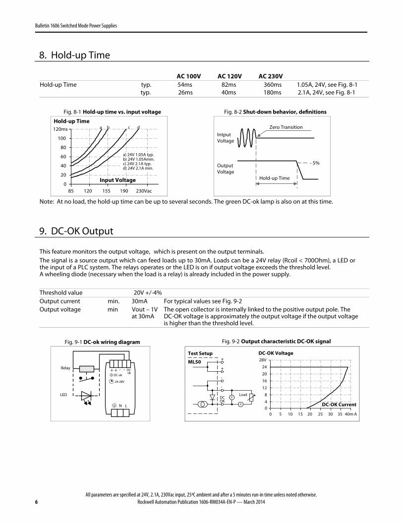
8. Hold-up Time
AC 100V AC 120V AC 230V Hold-up Time typ. 54ms 82ms 360ms 1.05A, 24V, see Fig. 8-1 typ. 26ms 40ms 180ms 2.1A, 24V, see Fig. 8-1
Fig. 8-1 Hold-up time vs. input voltage Fig. 8-2 Shut-down behavior, definitions
Note: At no load, the hold-up time can be up to several seconds. The green DC-ok lamp is also on at this time.
9. DC-OK Output
This feature monitors the output voltage, which is present on the output terminals. The signal is a source output which can feed loads up to 30mA. Loads can be a 24V relay (Rcoil < 700Ohm), a LED or the input of a PLC system. The relays operates or the LED is on if output voltage exceeds the threshold level. A wheeling diode (necessary when the load is a relay) is already included in the power supply.
Threshold value 20V +/-4% Output current min. 30mA For typical values see Fig. 9-2
Output voltage min Vout – 1V
at 30mA The open collector is internally linked to the positive output pole. The DC-OK voltage is approximately the output voltage if the output voltage is higher than the threshold level.
All parameters are specified at 24V, 2.1A, 230Vac input, 25ªC ambient and after a 5 minutes run-in time unless noted otherwise.Rockwell Automation Publication 1606-RM034A-EN-P — March 2014 7
Bulletin 1606 Switched Mode Power Supplies
10. Output
Output voltage nom. 24V Adjustment range min. 24-28V Guaranteed max. 30V At clockwise end position of potentiometer Factory setting 24.5V ±0.2%, at full load, cold unit Line regulation max. 10mV 85 to 264Vac Load regulation max. 100mV Static value, 0A 2.1A 0A Ripple and noise voltage max. 50mVpp 20Hz to 20MHz, 50Ohm Output capacitance typ. 1600μF Output current nom. 2.1A At 24V, see Fig. 10-1 nom. 1.8A At 28V, see Fig. 10-1 Output power nom. 50W Short-circuit current min. 3.1A Load impedance 400mOhm, see Fig. 10-1 max. 5A Load impedance 400mOhm, see Fig. 10-1
Fig. 10-1 Output voltage vs. output current, 230Vac, typ.
Output Voltage
00 1 2
4
8
12
28V
16
20
24
4A2.51.50.5 3 3.5
AdjustmentRange
Output Current
Peak current capability (up to several ms) The power supply can deliver a peak current which is higher than the specified short term current. This helps to startcurrent demanding loads or to safely operate subsequent circuit breakers. The extra current is supplied by the output capacitors inside the power supply. During this event, the capacitors will be discharged and cause a voltage dip on the output. Detailed curves can be found in section 27.1.
Peak current voltage dips typ. from 24V to 16V at 4.2A for 50ms, resistive load typ. from 24V to 15V at 10.5A for 2ms, resistive load typ. from 24V to 10.5V at 10.5A for 5ms, resistive load
All parameters are specified at 24V, 2.1A, 230Vac input, 25ªC ambient and after a 5 minutes run-in time unless noted otherwise.8 Rockwell Automation Publication 1606-RM034A-EN-P — March 2014
Bulletin 1606 Switched Mode Power Supplies
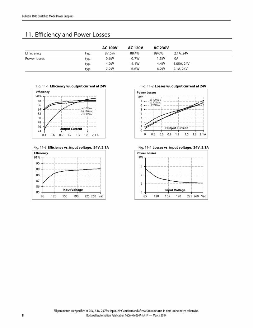
11. Efficiency and Power Losses
AC 100V AC 120V AC 230V %5.78 .pyt ycneiciffE 88.4% 89.0% 2.1A, 24V
W 0A3.1 W7.0 W6.0 .pytPower losses W 1.05A, 24V4.4 W1.4 W0.4 .pyt W 2.1A, 24V2.6 W6.6 W2.7 .pyt
Fig. 11-1 Efficiency vs. output current at 24V Fig. 11-2 Losses vs. output current at 24V
Efficiency
0.3
76788082848688
74
90%
2.1 A0.9 1.2 1.8
Output Current
0.6 1.5
a) 100Vacb) 120Vacc) 230Vac
b
ca
Power Losses
1.23.00 A01
3456
8W
2
7
0.6 0.9 1.2
Output Current
1.5 1.8
a) 100Vacb) 120Vacc) 230Vac
a
bc
a
bc
Fig. 11-3 Efficiency vs. input voltage, 24V, 2.1A Fig. 11-4 Losses vs. input voltage, 24V, 2.1A
Efficiency
85 120 155 190 225 260 Vac85
86
87
88
Input Voltage
89
90
91%
Power Losses
5
6
7
8
Input Voltage
9W
85 120 155 190 225 260 Vac
All parameters are specified at 24V, 2.1A, 230Vac input, 25ªC ambient and after a 5 minutes run-in time unless noted otherwise.Rockwell Automation Publication 1606-RM034A-EN-P — March 2014 9
Bulletin 1606 Switched Mode Power Supplies
12. Functional Diagram
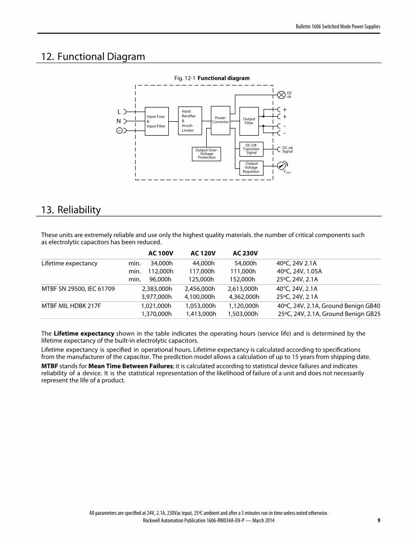
Fig. 12-1 Functional diagram
Input Fuse&Input Filter
LN
Output Over-Voltage
Protection
DC-OKTransistor
Signal
InputRectifier&InrushLimiter
PowerConverter
OutputVoltage
Regulator
++
--
OutputFilter
V OUT
DCok
DC-okSignal
13. Reliability
These units are extremely reliable and use only the highest quality materials. the number of critical components suchas electrolytic capacitors has been reduced.
AC 100V AC 120V AC 230V
Lifetime expectancy min. 34,000h 44,000h 54,000h 40ºC, 24V 2.1A min. 112,000h 117,000h 111,000h 40ºC, 24V, 1.05A min. 96,000h 125,000h 152,000h 25ºC, 24V, 2.1A
The Lifetime expectancy shown in the table indicates the operating hours (service life) and is determined by the lifetime expectancy of the built-in electrolytic capacitors. Lifetime expectancy is specified in operational hours. Lifetime expectancy is calculated according to specificationsfrom the manufacturer of the capacitor. The prediction model allows a calculation of up to 15 years from shipping date. MTBF stands for Mean Time Between Failures; it is calculated according to statistical device failures and indicates reliability of a device. It is the statistical representation of the likelihood of failure of a unit and does not necessarilyrepresent the life of a product.
All parameters are specified at 24V, 2.1A, 230Vac input, 25ªC ambient and after a 5 minutes run-in time unless noted otherwise.10 Rockwell Automation Publication 1606-RM034A-EN-P — March 2014
Bulletin 1606 Switched Mode Power Supplies
14. Front Side and User Elements
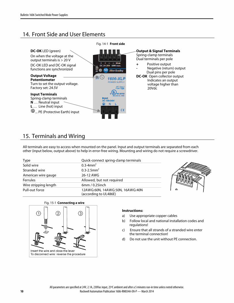
Fig. 14-1 Front side
DC-OK LED (green) On when the voltage at the output terminals is > 20 V DC-OK LED and DC-OK signal functions are synchronized
Output Voltage Potentiometer Turn to set the output voltage. Factory set: 24.5V
Input Terminals Spring-clamp terminals N … Neutral input L … Line (hot) input
... PE (Protective Earth) input
Output & Signal Terminals Spring-clamp terminals Dual terminals per pole + Positive output - Negative (return) output Dual pins per pole DC-OK Open collector output Indicates an output voltage higher than 20Vdc
15. Terminals and Wiring
All terminals are easy to access when mounted on the panel. Input and output terminals are separated from eachother (input below, output above) to help in error-free wiring. Mounting and wiring do not require a screwdriver.
mm5.2-3.0 eriw dednartS 2 American wire gauge 26-12 AWG
deriuqer ton tub ,dewollA selurreF Wire stripping length 6mm / 0.25inch
N04:GWA61 ,N05:GWA41 ,N06:GWA21 ecrof tuo-lluP(according to UL486E)
Fig. 15-1 Connecting a wire
Instructions: a) Use appropriate copper cables b) Follow local and national installation codes and
regulations! c) Ensure that all strands of a stranded wire enter
the terminal connection! d) Do not use the unit without PE connection.
All parameters are specified at 24V, 2.1A, 230Vac input, 25ªC ambient and after a 5 minutes run-in time unless noted otherwise.Rockwell Automation Publication 1606-RM034A-EN-P — March 2014 11
Bulletin 1606 Switched Mode Power Supplies
16. EMC
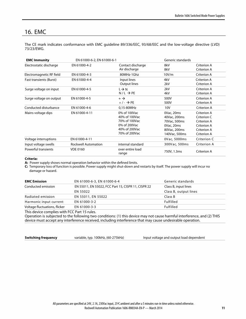
The CE mark indicates conformance with EMC guideline 89/336/EEC, 93/68/EEC and the low-voltage directive (LVD) 73/23/EWG.
EMC Immunity EN 61000-6-2, EN 61000-6-1 Generic standards
Electrostatic discharge EN 61000-4-2 Contact discharge
Air discharge 8kV 8kV
Criterion A Criterion A
Electromagnetic RF field EN 61000-4-3 80MHz-1Ghz 10V/m Criterion A
Fast transients (Burst) EN 61000-4-4 Input lines 4kV Criterion A
Output lines 2kV Criterion A
Surge voltage on input EN 61000-4-5 L N N / L PE
2kV 4kV
Criterion A Criterion A
Surge voltage on output EN 61000-4-5 + -
+ / - PE 500V 500V
Criterion A Criterion A
Conducted disturbance EN 61000-4-6 0,15-80MHz 10V Criterion A
Criterion A Criterion C Criterion A Criterion A Criterion A Criterion A
C noiretirC sm0005 ,caV0 Voltage interruptions EN 61000-4-11 Input voltage swells Rockwell Automation internal standard A noiretirC sm005 ,caV003
Powerful transients VDE 0160 over entire load
range 750V, 1.3ms Criterion A
Criteria: A: Power supply shows normal operation behavior within the defined limits. C: Temporary loss of function is possible. Power supply might shut-down and restarts by itself. The power supply will incur no
damage or hazard.
EMC Emission sdradnats cireneG 4-6-00016 NE ,3-6-00016 NE Conducted emission EN 55011, EN 55022, FCC Part 15, CISPR 11, CISPR 22 Class B, input lines
senil tuptuo ,B ssalC 22055 NE B ssalC 22055 NE ,11055 NE noissime detaidaR
dellifluF 2-3-00016 NE tnerruc tupni cinomraH Voltage fluctuations, flicker dellifluF 3-3-00016 NE
This device complies with FCC Part 15 rules. Operation is subjected to the following two conditions: (1) this device may not cause harmful interference, and (2) THISdevice must accept any interference received, including interference that may cause undesirable operation.
Switching frequency variable, typ. 100kHz, (60-275kHz) Input voltage and output load dependent
All parameters are specified at 24V, 2.1A, 230Vac input, 25ªC ambient and after a 5 minutes run-in time unless noted otherwise.12 Rockwell Automation Publication 1606-RM034A-EN-P — March 2014
Bulletin 1606 Switched Mode Power Supplies
17. Environment
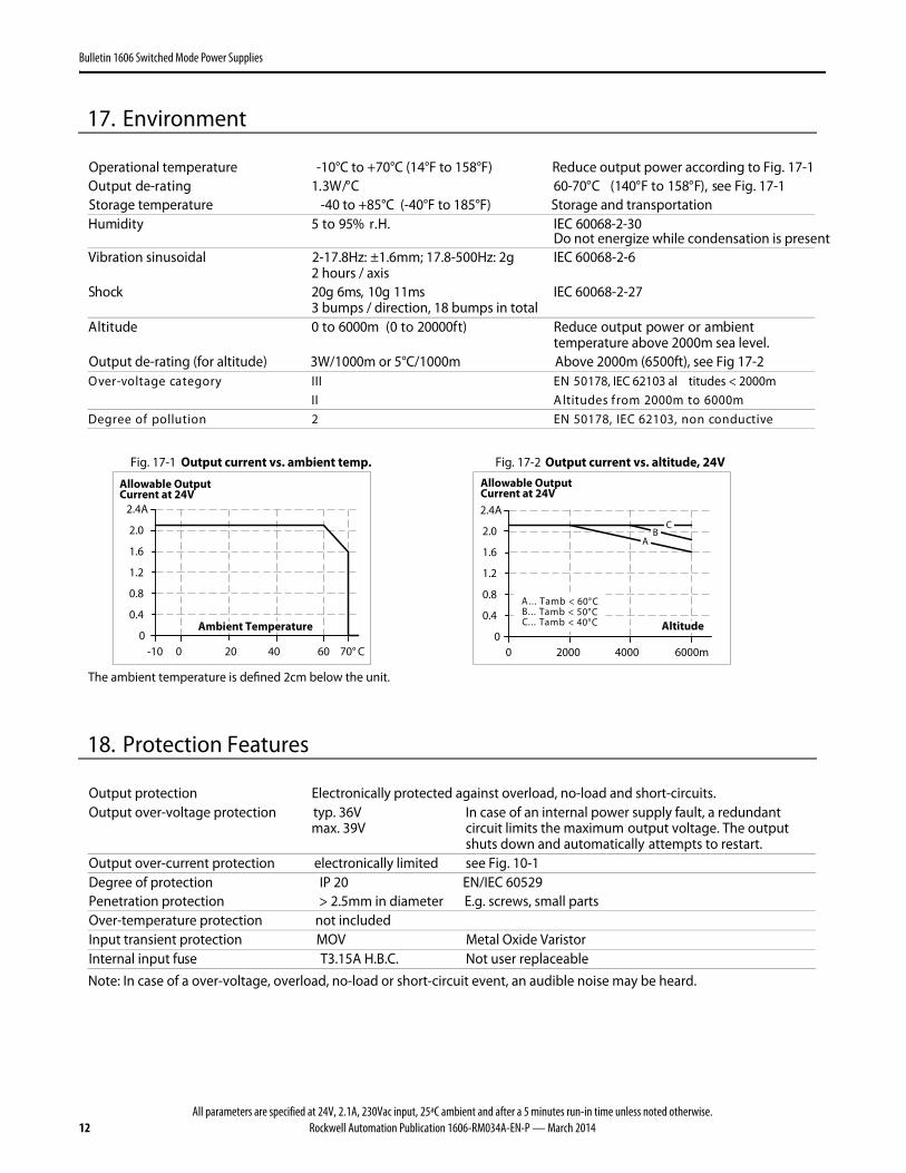
Operational temperature -10°C to +70°C (14°F to 158°F) Reduce output power according to Fig. 17-1 ees ,)F°851 ot F°041( C°07-06 C°/W3.1 gnitar-ed tuptuO Fig. 17-1
Storage temperature -40 to +85°C (-40°F to 185°F) Storage and transportation
03-2-86006 CEI .H.r %59 ot 5 ytidimuHDo not energize while condensation is present
3 bumps / direction, 18 bumps in total IEC 60068-2-27
tneibma ro rewop tuptuo ecudeR )tf00002 ot 0( m0006 ot 0 edutitlA temperature above 2000m sea level.
Output de-rating (for altitude) 3W/1000m or 5°C/1000m Above 2000m (6500ft), see Fig 17-2 05 NE III yrogetac egatlov-revO 178, IEC 62103 al titudes < 2000m
m0006 ot m0002 morf sedutitlA II evitcudnoc non ,30126 CEI ,87105 NE 2 noitullop fo eergeD
Fig. 17-1 Output current vs. ambient temp. Fig. 17-2 Output current vs. altitude, 24V
The ambient temperature is defined 2cm below the unit.
18. Protection Features
Output protection Electronically protected against overload, no-load and short-circuits. Output over-voltage protection typ. 36V
max. 39V In case of an internal power supply fault, a redundant circuit limits the maximum output voltage. The output shuts down and automatically attempts to restart.
Output over-current protection electronically limited see Fig. 10-1 Degree of protection IP 20 EN/IEC 60529 Penetration protection > 2.5mm in diameter E.g. screws, small parts Over-temperature protection not included Input transient protection MOV Metal Oxide Varistor Internal input fuse T3.15A H.B.C. Not user replaceable
Note: In case of a over-voltage, overload, no-load or short-circuit event, an audible noise may be heard.
All parameters are specified at 24V, 2.1A, 230Vac input, 25ªC ambient and after a 5 minutes run-in time unless noted otherwise.Rockwell Automation Publication 1606-RM034A-EN-P — March 2014 13
Bulletin 1606 Switched Mode Power Supplies
19. Safety
Input / output separation SELV IEC/EN 60950-1 14-4-46306 CEI ,30126 CEI ,87105 NE ,1-40206 NE VLEP
nier ro elbuod forced insulation deriuqer noitcennoc )htraE evitcetorP( EP I noitcetorp fo ssalC
Isolation resistance > 5MOhm input to output, 500Vdc Touch current (leakage current) typ. 0.12mA 100Vac, 50Hz, TN mains
sniam NT ,zH06 ,caV021 Am71.0 .pyt sniam NT ,zH05 ,caV032 Am92.0 .pyt sniam NT ,zH05 ,caV011 Am61.0 < sniam NT ,zH06 ,caV231 Am32.0 < sniam NT ,zH05 ,caV462 Am04.0 <
20. Dielectric Strength
Fig. 20-1 Dielectric strength A B C Type test 60s 2500Vac 3000Vac 500Vac Factory test 5s 2500Vac 2500Vac 500Vac Field test 5s 2000Vac 2000Vac 500Vac
A
C
NL
Input
Earth, PE
BOutput
-
+
DC-Ok
Type tests and factory tests: Conducted by the manufacturer. Do not repeat test in field! Rules for field test: Use appropriate test equipment which applies the voltage with a slow ramp! Connect L and N together as well as all output poles.
The output voltage is floating and had no ohmic connection to ground. To fulfill the PELV requirements according to EN60204-1 § 6.4.1, it is recommended that either the + pole, the - poleor any other part of the output circuit be connected to the protective earth system. This helps to avoidsituations in which a load starts unexpectedly or cannot be switched off in the occurence of unnoticed earth faults.
All parameters are specified at 24V, 2.1A, 230Vac input, 25ªC ambient and after a 5 minutes run-in time unless noted otherwise.14 Rockwell Automation Publication 1606-RM034A-EN-P — March 2014
Bulletin 1606 Switched Mode Power Supplies
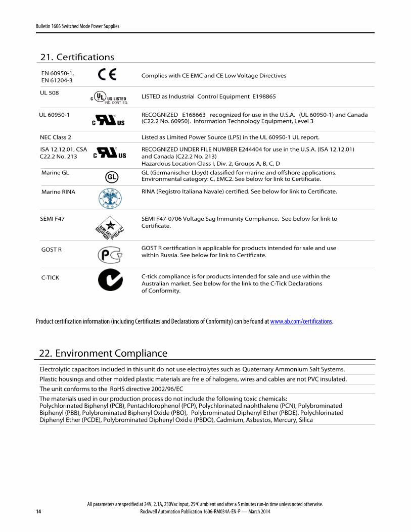
Product certification information (including Certificates and Declarations of Conformity) can be found at www.ab.com/certifications.
21. Certifications
UL 508
IND. CONT. EQ. LISTED as Industrial Control Equipment E198865
UL 60950-1
RECOGNIZED E168663 recognized for use in the U.S.A. (UL 60950-1) and Canada (C22.2 No. 60950). Information Technology Equipment, Level 3
NEC Class 2
Listed as Limited Power Source (LPS) in the UL 60950-1 UL report.
ISA 12.12.01, CSA C22.2 No. 213
RECOGNIZED UNDER FILE NUMBER E244404 for use in the U.S.A. (ISA 12.12.01)and Canada (C22.2 No. 213)Hazardous Location Class I, Div. 2, Groups A, B, C, D
Marine GL GL GL (Germanischer Lloyd) classified for marine and offshore applications.Environmental category: C, EMC2. See below for link to Certificate.
SEMI F47
SEMI F47-0706 Voltage Sag Immunity Compliance. See below for link toCertificate.
EN 60950-1,EN 61204-3
Complies with CE EMC and CE Low Voltage Directives
Marine RINA RINA (Registro Italiana Navale) certified. See below for link to Certificate.
GOST R GOST R certification is applicable for products intended for sale and usewithin Russia. See below for link to Certificate.
C-TICK C-tick compliance is for products intended for sale and use within theAustralian market. See below for the link to the C-Tick Declarationsof Conformity.
22. Environment Compliance
Electrolytic capacitors included in this unit do not use electrolytes such as Quaternary Ammonium Salt Systems.
Plastic housings and other molded plastic materials are fre e of halogens, wires and cables are not PVC insulated.
The unit conforms to the RoHS directive 2002/96/EC
The materials used in our production process do not include the following toxic chemicals: Polychlorinated Biphenyl (PCB), Pentachlorophenol (PCP), Polychlorinated naphthalene (PCN), Polybrominated Biphenyl (PBB), Polybrominated Biphenyl Oxide (PBO), Polybrominated Diphenyl Ether (PBDE), Polychlorinated Diphenyl Ether (PCDE), Polybrominated Diphenyl Oxid e (PBDO), Cadmium, Asbestos, Mercury, Silica
All parameters are specified at 24V, 2.1A, 230Vac input, 25ªC ambient and after a 5 minutes run-in time unless noted otherwise.Rockwell Automation Publication 1606-RM034A-EN-P — March 2014 15
Bulletin 1606 Switched Mode Power Supplies
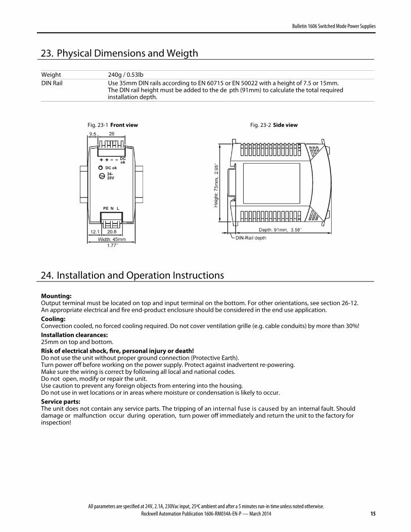
23. Physical Dimensions and Weigth
Weight 240g / 0.53lb DIN Rail Use 35mm DIN rails according to EN 60715 or EN 50022 with a height of 7.5 or 15mm.
The DIN rail height must be added to the de pth (91mm) to calculate the total required installation depth.
Fig. 23-1 Front view Fig. 23-2 Side view
24. Installation and Operation Instructions
Mounting: Output terminal must be located on top and input terminal on the bottom. For other orientations, see section 26-12. An appropriate electrical and fire end-product enclosure should be considered in the end use application.Cooling: Convection cooled, no forced cooling required. Do not cover ventilation grille (e.g. cable conduits) by more than 30%! Installation clearances: 25mm on top and bottom. Risk of electrical shock, fire, personal injury or death!Do not use the unit without proper ground connection (Protective Earth).Turn power off before working on the power supply. Protect against inadvertent re-powering.Make sure the wiring is correct by following all local and national codes. Do not open, modify or repair the unit. Use caution to prevent any foreign objects from entering into the housing.Do not use in wet locations or in areas where moisture or condensation is likely to occur.Service parts: The unit does not contain any service parts. The tripping of an internal fuse is caused by an internal fault. Should damage or malfunction occur during operation, turn power off immediately and return the unit to the factory forinspection!
All parameters are specified at 24V, 2.1A, 230Vac input, 25ªC ambient and after a 5 minutes run-in time unless noted otherwise.16 Rockwell Automation Publication 1606-RM034A-EN-P — March 2014
Bulletin 1606 Switched Mode Power Supplies
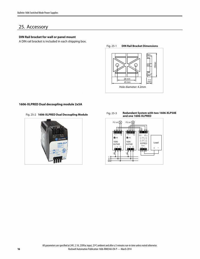
25. Accessory
DIN Rail bracket for wall or panel mount
A DIN rail bracket is included in each shipping box. Fig. 25-1 DIN Rail Bracket Dimensions
Hole diameter: 4.2mm
1606-XLPRED Dual decoupling module 2x5A
Fig. 25-2 1606-XLPRED Dual Decoupling Module Fig. 25-3 Redundant System with two 1606-XLP50E
and one 1606-XLPRED
XLPREDVOUT
V IN 1
+ + - -
+ - + -VIN 2
1606-XLP50E
adj.
L N
+ + - - DCok
1606-XLP50E
adj.
L N
+ + - - DCok
LN
PS1 ok PS2 ok
Load
+ -
I I
All parameters are specified at 24V, 2.1A, 230Vac input, 25ªC ambient and after a 5 minutes run-in time unless noted otherwise.Rockwell Automation Publication 1606-RM034A-EN-P — March 2014 17
Bulletin 1606 Switched Mode Power Supplies
26. Application Notes
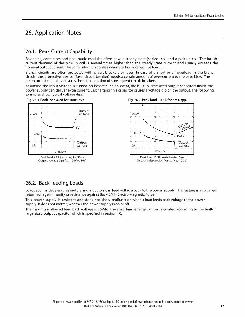
26.1. Peak Current Capability Solenoids, contactors and pneumatic modules often have a steady state (sealed) coil and a pick-up coil. The inrush current demand of the pick-up coil is several times higher than the steady state curre nt and usually exceeds the nominal output current. The same situation applies when starting a capacitive load.Branch circuits are often protected with circuit breakers or fuses. In case of a short or an overload in the branch circuit, the protective device (fuse, circuit breaker) needs a certain amount of over-current to trip or to blow. Thepeak current capability ensures the safe operation of subsequent circuit breakers.Assuming the input voltage is turned on before such an event, the built-in large sized output capacitors inside thepower supply can deliver extra current. Discharging this capacitor causes a voltage dip on the output. The followingexamples show typical voltage dips: Fig. 26-1 Peak load 4.2A for 50ms, typ. Fig. 26-2 Peak load 10.5A for 5ms, typ.
10ms/DIV
OutputVoltage
OutputCurrent
24.0V
0A
4.2A
16V
1ms/DIV
Output
V oltage
OutputCurrent
24.0V
0A
10.5A10.5V
Peak load 4.2A (resistive) for 50ms
Output voltage dips from 24V to 16V. Peak load 10.5A (resistive) for 5ms
Output voltage dips from 24V to 10.5V.
26.2. Back-feeding Loads Loads such as decelerating motors and inductors can feed voltag e back to the power supply. This feature is also called return voltage immunity or resistance against Back-EMF (Electro Magnetic Force).This power supply is resistant and does not show malfunction when a load feeds back voltage to the powersupply. It does not matter, whether the power supply is on or off. The maximum allowed feed back voltage is 35Vdc. The absorbing energy can be calculated according to the built-in large sized output capacitor which is specified in section 10.
All parameters are specified at 24V, 2.1A, 230Vac input, 25ªC ambient and after a 5 minutes run-in time unless noted otherwise.18 Rockwell Automation Publication 1606-RM034A-EN-P — March 2014
Bulletin 1606 Switched Mode Power Supplies
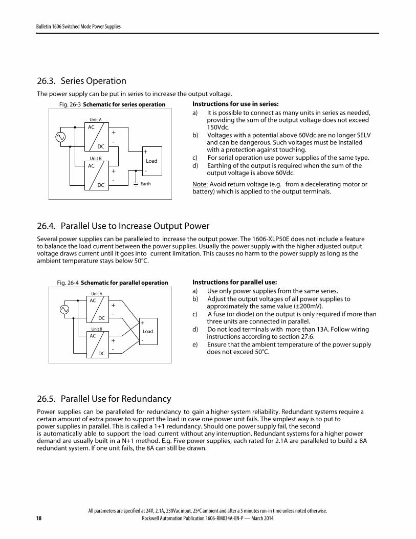
26.3. Series Operation The power supply can be put in series to increase the output voltage.
Fig. 26-3 Schematic for series operation Instructions for use in series:
Earth
Unit A
AC
DC
Unit B
AC
DC
-
+-
+
Load
+
-
a) It is possible to connect as many units in series as needed, providing the sum of the output voltage does not exceed150Vdc.
b) Voltages with a potential above 60Vdc are no longer SELVand can be dangerous. Such voltages must be installed with a protection against touching.
c) For serial operation use power supplies of the same type. d) Earthing of the output is required when the sum of the
output voltage is above 60Vdc.
Note: Avoid return voltage (e.g. from a decelerating motor or battery) which is applied to the output terminals.
26.4. Parallel Use to Increase Output Power Several power supplies can be paralleled to increase the output power. The 1606-XLP50E does not include a featureto balance the load current between the power supplies. Usually the power supply with the higher adjusted output voltage draws current until it goes into current limitation. This causes no harm to the power supply as long as theambient temperature stays below 50°C.
Fig. 26-4 Schematic for parallel operation Instructions for parallel use:
Unit A
AC
DC
Unit B
AC
DC
-
+-
+
Load
+
-
a) Use only power supplies from the same series. b) Adjust the output voltages of all power supplies to
approximately the same value (±200mV). c) A fuse (or diode) on the output is only required if more than
three units are connected in parallel. d) Do not load terminals with more than 13A. Follow wiring
instructions according to section 27.6. e) Ensure that the ambient temperature of the power supply
does not exceed 50°C.
26.5. Parallel Use for Redundancy Power supplies can be paralleled for redundancy to gain a higher system reliability. Redundant systems require a certain amount of extra power to support the load in case one power unit fails. The simplest way is to put to power supplies in parallel. This is called a 1+1 redundancy. Should one power supply fail, the secondis automatically able to support the load current without any interruption. Redundant systems for a higher powerdemand are usually built in a N+1 method. E.g. Five power supplies, each rated for 2.1A are paralleled to build a 8A redundant system. If one unit fails, the 8A can still be drawn.
All parameters are specified at 24V, 2.1A, 230Vac input, 25ªC ambient and after a 5 minutes run-in time unless noted otherwise.Rockwell Automation Publication 1606-RM034A-EN-P — March 2014 19
Bulletin 1606 Switched Mode Power Supplies
Please note: This simple way to build a redundant system has two major disadvantages.- The faulty power supply cannot be identified. The green LED will still be on since it is reverse-powered from
the other power supply. - It does not cover failures such as an internal short circuit in the secondary side of the power supply. In such a
situation the defective unit becomes a load for the other power supplies and the output voltage can nolonger be maintained.
The above conditions can be avoided by using decoupling diodes which are included in the 1606-XLPRED decoupling module. Other recommendations for building redundant power systems: a) Use separate input fuses for each power supply. b) Monitor the individual power s upply units. A DC-ok output is included in the 1606-XLP50E and 1606-XLP50EZ
In all other cases, use the the 1606-XLERED redundancy module which includes a monitoring circuit for each input.
c) When possible, connect each power supply to different phases of the mains network.
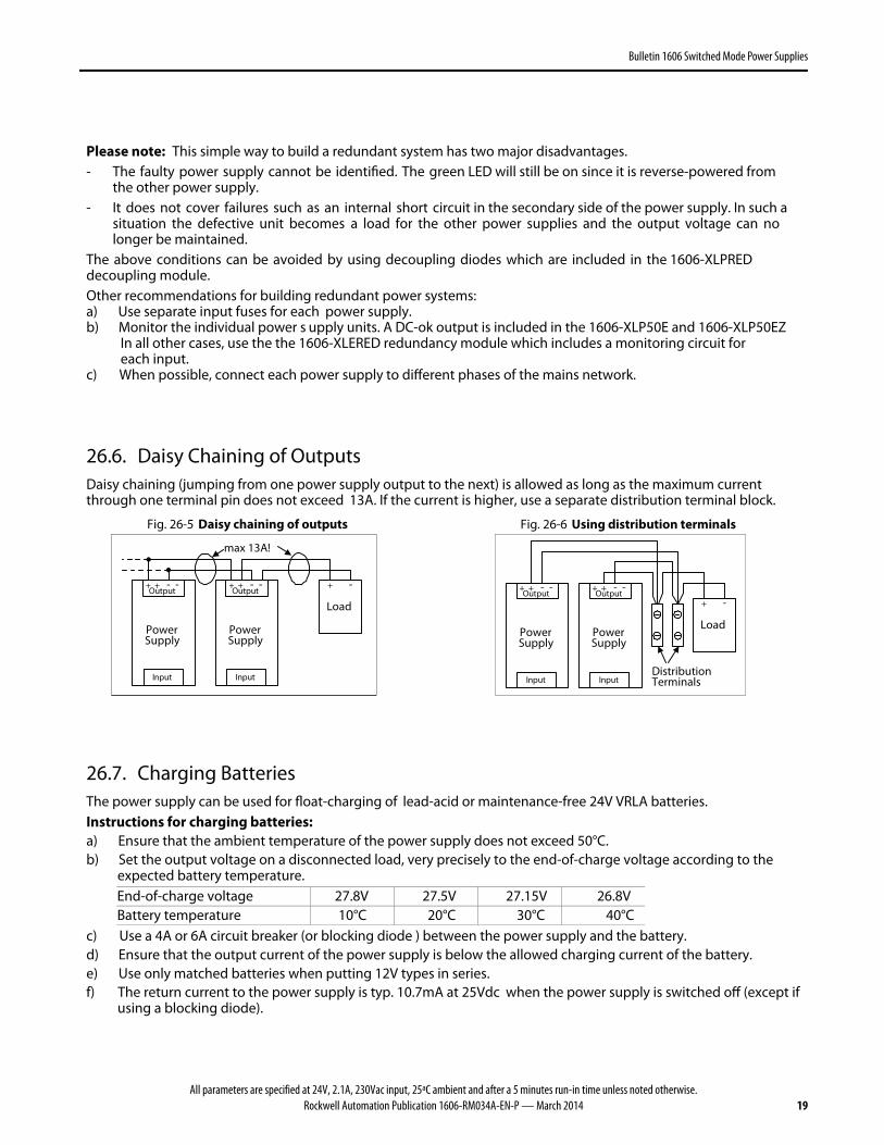
26.6. Daisy Chaining of Outputs Daisy chaining (jumping from one power supply output to the next) is allowed as long as the maximum currentthrough one terminal pin does not exceed 13A. If the current is higher, use a separate distribution terminal block.
Fig. 26-5 Daisy chaining of outputs Fig. 26-6 Using distribution terminals
PowerSupply
+ + - -
Input
Output
Load
+ -
max 13A!
PowerSupply
+ + - -
Input
Output
Load
+ -
DistributionTerminals
PowerSupply
+ + - -
Input
Output
PowerSupply
+ + - -
Input
Output
26.7. Charging Batteries The power supply can be used for float-charging of lead-acid or maintenance-free 24V VRLA batteries. Instructions for charging batteries: a) Ensure that the ambient temperature of the power supply does not exceed 50°C. b) Set the output voltage on a disconnected load, very precisely to the end-of-charge voltage according to the
expected battery temperature. End-of-charge voltage 27.8V 27.5V 27.15V 26.8V Battery temperature 10°C 20°C 30°C 40°C
c) Use a 4A or 6A circuit breaker (or blocking diode ) between the power supply and the battery. d) Ensure that the output current of the power supply is below the allowed charging current of the battery. e) Use only matched batteries when putting 12V types in series. f) The return current to the power supply is typ. 10.7mA at 25Vdc when the power supply is switched off (except if
using a blocking diode).
All parameters are specified at 24V, 2.1A, 230Vac input, 25ªC ambient and after a 5 minutes run-in time unless noted otherwise.20 Rockwell Automation Publication 1606-RM034A-EN-P — March 2014
Bulletin 1606 Switched Mode Power Supplies
26.8. External Input Protection The unit is tested and approved for branch circuits up to 15A (UL) or 16A (IEC). External protection is required only ifthe supplying branch has an ampacity greater than this. In some countries, local regulations may apply, so check local codes and requirements. If using an external protective device, a minimum value is required to avoid undesired tripping of the fuse.
citsiretcarahC-C citsiretcarahC-B Ampacity max. min. 10A 6A
15A (UL), 16A (IEC) 15A (UL), 16A (IEC)
26.9. Inductive and Capacitive Loads The unit is designed to supply any type of load, including unlimited capacitive and inductive loads.
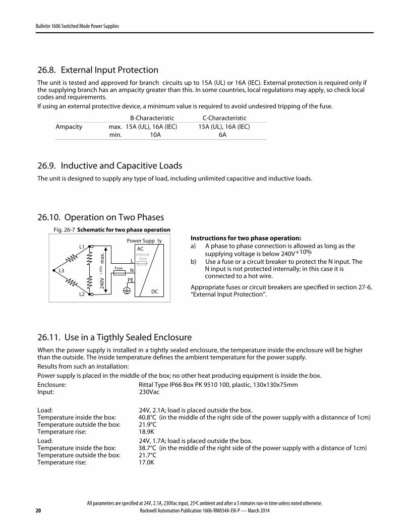
26.10. Operation on Two Phases Fig. 26-7 Schematic for two phase operation
240V
+10%
max
.
Fuse
L2
L1
L3
L
N
PE
Power Supp ly
AC
DC
internalfuse
Instructions for two phase operation: a) A phase to phase connection is allowed as long as the
supplying voltage is below 240V+10%. b) Use a fuse or a circuit breaker to protect the N input. The
N input is not protected internally; in this case it isconnected to a hot wire.
Appropriate fuses or circuit breakers are specified in section 27-6,“External Input Protection”.
26.11. Use in a Tigthly Sealed Enclosure When the power supply is installed in a tightly sealed enclosure, the temperature inside the enclosure will be higherthan the outside. The inside temperature defines the ambient temperature for the power supply.Results from such an installation: Power supply is placed in the middle of the box; no other heat producing equipment is inside the box. Enclosure: Rittal Type IP66 Box PK 9510 100, plastic, 130x130x75mm Input: 230Vac
Load: 24V, 2.1A; load is placed outside the box.Temperature inside the box: 40.8°C (in the middle of the right side of the power supply with a distannce of 1cm)Temperature outside the box: 21.9°C Temperature rise: 18.9K Load: 24V, 1.7A; load is placed outside the box.Temperature inside the box: 38.7°C (in the middle of the right side of the power supply with a distance of 1cm)Temperature outside the box: 21.7°C Temperature rise: 17.0K
All parameters are specified at 24V, 2.1A, 230Vac input, 25ªC ambient and after a 5 minutes run-in time unless noted otherwise.Rockwell Automation Publication 1606-RM034A-EN-P — March 2014 21
Bulletin 1606 Switched Mode Power Supplies
26.12. Mounting Orientations Mounting orientations other than input terminals on the bottom and output on the top require a reduction in continuous output power or a limitation in the maximum allowed ambient temperature. The amount of reduction influences the lifetime expectancy of the power supply. Therefore, two different derating curves for continuous operation can be found below:
Curve A1 Recommended output current. Curve A2 Max allowed output current (results in approximately half the lifetime expectancy of A1).
Fig. 26-8 Mounting Orientation A (Standard orientation) Power
Supply
INPUT
OUTPUT
Output Current
010 20 30 40 60°C
4
1216
20A
50
A1
8
Ambient Temperature
Fig. 26-9 Mounting Orientation B (Upside down)
Power Supply
INPUT
OUTPUT
Output Current
010 20 30 40 60°C
4
1216
20A
50
A1
8
Ambient Temperature
Fig. 26-10 Mounting Orientation C (Table-top mounting)
Output Current
010 20 30 40 60°C
4
1216
20A
50
8A1
A2
Ambient Temperature
Fig. 26-11 Mounting Orientation D (Horizontal cw)
Pow
er Su
pp
ly
INPU
T
OU
TPUT
Output Current
010 20 30 40 60°C
4
1216
20A
50
8A1
A2
Ambient Temperature
Fig. 26-12 Mounting Orientation E (Horizontal ccw)
Pow
er S
up
ply
INPU
T
OU
TPU
T
Output Current
010 20 30 40 60°C
4
1216
20A
50
8A1
A2
Ambient Temperature
Rockwell Automation Support
Rockwell Automation provides technical information on the Web to assist you in using its products. At http://www.rockwellautomation.com/support, you can find technical manuals, technical and application notes, sample code and links to software service packs, and a MySupport feature that you can customize to make the best use of these tools. You can also visit our Knowledgebase at http://www.rockwellautomation.com/knowledgebase for FAQs, technical information, support chat and forums, software updates, and to sign up for product notification updates.
For an additional level of technical phone support for installation, configuration, and troubleshooting, we offer TechConnectSM support programs. For more information, contact your local distributor or Rockwell Automation representative, or visit http://www.rockwellautomation.com/support/.
Installation Assistance
If you experience a problem within the first 24 hours of installation, review the information that is contained in this manual. You can contact Customer Support for initial help in getting your product up and running.
New Product Satisfaction Return
Rockwell Automation tests all of its products to help ensure that they are fully operational when shipped from the manufacturing facility. However, if your product is not functioning and needs to be returned, follow these procedures.
Documentation Feedback
Your comments will help us serve your documentation needs better. If you have any suggestions on how to improve this document, complete this form, publication RA-DU002, available at http://literature.rockwellautomation.com/idc/groups/literature/documents/du/ra-du002_-en-e.pdf.
United States or Canada 1.440.646.3434
Outside United States or Canada Use the Worldwide Locator at http://www.rockwellautomation.com/rockwellautomation/support/overview.page, or contact your local Rockwell Automation representative.
United States Contact your distributor. You must provide a Customer Support case number (call the phone number above to obtain one) to your distributor to complete the return process.
Outside United States Please contact your local Rockwell Automation representative for the return procedure.