TABLE OF CONTENTSIntro ...........................................................................................1 Tremco BUR Systems - Design and Confirguration .......................1 Product List for BUR Systems .....................................................2-3System Descriptions - Cold and Hot BUR ......................................4 General Requirements ...................................................................5-
COPYR IGHTThis document contains information that is protected by copyright. Neither extractsnor the documentation as a whole may be photocopied, reproduced, translated, orput into data carriers without prior approval.
BU
RTremco® Roofing & Building Maintenance
3735 Green Road • Beachwood, Ohio 44122216.292.5000 • www.tremcoroofing.com
INTRODUCT ION Tremco BURmastic cold-applied built-up roofs and THERM hot-applied built-up roofsystems are designed for use on low-slope structures in North America. Tremcobuilt-up roofs are formulated from select asphalt blends, polymer modifiers, andengineered reinforcing fabrics to comprise a roofing system designed to providedurability and years of watertight performance.
Tremco BUR systems are installed in multi-ply configurations consisting of basesheet and ply sheets adhered with hot or cold adhesives. Tremco BUR systems maybe finished with a variety of roof surfacings including flood coats and aggregate andreflective coatings.
TREMCO BUR ROOF SYSTEMS – DES IGN AND SPEC IF ICAT IONTremco BUR systems are constructed with a minimum of 3 plies and may use moredepending on the design criteria. Approved BUR configurations are defined asproduct combinations that have been determined by Tremco to be compatiblesystem components and have been tested in accordance with Tremco and industrystandards and found to exceed minimum performance requirements.
PRODUCT L IST FOR BUR SYSTEMS :Base Sheets / Cold Applied Ply Sheets:The base/ply sheets listed below are suitable for application as base sheets in hot applied roofs and asbase/ply sheets in cold-applied roofing systems.
Base Sheets / Cold Applied Ply Sheets: SQ/rol lASTM SpecBURmastic Composite ply HT 2 Exceeds D4601 Type IIBURmastic Composite Ply Premium 2 Exceeds D4601 Type IIBURmastic Composite Ply Supreme 2 Exceeds D4601 Type IIBURmastic Composite Ply HT Green 2 Exceeds D4601 Type IIBURmastic Composite Ply Premium Green 2 Exceeds D4601 Type IIBURmastic Glass Ply 2 Exceeds D4601 Type IIBURmastic Glass Ply 28 lb. 3 Exceeds D4601 Type II
Hot Applied Ply Sheets: The ply sheets listed below are for use in built-up roof systems and are used in conjunction with hot asphaltadhesives.
Hot Applied Ply Sheets:SQ/rollASTM SpecTHERMglass Type IV 5 D2178, Type IVTHERMglass Premium Type VI 5 D2178, Type VIPolyTHERM Roofing Ply 10 190 g/m2
Cold BUR Adhesives:The adhesives listed below are for use in cold-applied roof systems in conjunction with cold-applied base/plysheets.
Hot BUR Adhesives:The hot-melt adhesives listed below are for use in hot-applied roof systems along with approved base/plysheets.
Hot BUR AdhesivesEVTASTM SpecTHERMastic 425° F D6152, 1000% ElongationTHERMastic 80 425° F D6152, 800% ElongationPremium III Asphalt 425° + 25° F D312, Type IIIPremium IV Asphalt 450° + 25° F D312, Type IV
Cold Applied Roof Surfacing:The surfacing options listed below are suitable for use over hot or cold applied roof systems.
Cold Applied Surfacing / CoatingsBURmastic Adhesive and AggregateBURmastic LV Adhesive and AggregateBURmastic Green Adhesive and AggregateEcolastic and AggregateRock-It Adhesive and White AggregateTremlastic SP and Polarcote FRTremlastic SP and Double Duty AluminumTremlastic SP and ICE CoatingTremlastic SP and Alumanation 301ICE CoatingAlumanation 301
Hot Applied Roof Surfacing:The surfacing options listed below are suitable for use over hot-applied roof systems only.
Hot Applied SurfacingTHERMastic and AggregateTHERMastic 80 and AggregatePremium II Asphalt and AggregatePremium IV Asphalt and Aggregate
SYSTEM DESCRIPT IONS Cold BUR:BURmastic 100: A cold-applied, built-up roof system reinforced with fiberglass ply sheetsBURmastic 200: A cold-applied, built-up roof system reinforced with composite polyester / fiberglass ply sheets
Hot BUR:BURmastic 100: A cold-applied, built-up roof system reinforced with fiberglass ply sheetsBURmastic 200: A cold-applied, built-up roof system reinforced with composite polyester / fiberglass ply sheets
GENERAL REQUIREMENTS : Roof DecksDecking must be designed and constructed to provide sufficient support for anticipated loads withoutexcessive deflection or movement. Provisions for expansion and contraction shall be incorporated into thedesign. The deck shall be constructed according to the deck manufacturer’s or design professional’sspecifications, following established practices, which includes attachment to the structural supports for thebuilding.
Tremco takes responsibility for providing quality materials and for specifications and recommendations for theirproper installation. As neither Tremco nor its representatives practice architecture or engineering, Tremco offersno opinion, and expressly disclaims any responsibility for the soundness of any structure on which its productsmay be applied.
If questions arise as to the soundness of a structure or its ability to properly support a planned installation, theowner should obtain the opinions of competent structural engineers before proceeding. Tremco accepts noliability for any structural failure or for resultant damages. Tremco Representatives are not authorized to varythis disclaimer.
Decking shall be designed to provide positive drainage toward roof edges or drains. Tremco BURmastic andTHERM built-up roof systems require a minimum slope of ¼” per foot. If the deck does not meet this minimumslope requirement, slope may be increased through the use of tapered insulation or a Tremco approvedlightweight insulated concrete system (LWIC) prior to installation of BUR roof systems.
Certain roof decks may require the use of specific fastener designs in order to achieve acceptable attachmentstrength. Please contact your local Tremco Representative for information on approved fastener brandsapproved for use on specific roof deck types.
Vapor Retarder/Air Barrier A vapor retarder and/or air barrier assembly may be specified to improve energy efficiency for the building.This air/vapor membrane is intended to tie-in with other vapor retarder /air barrier assemblies within other partsof the structure, such as the walls. In addition, a vapor retarder may be required if the building is located in acold weather climate, or where the wintertime relative humidity is considerably higher, possibly due toprocesses or activities in the building which generate heat and moisture. Closely coordinate the proper tie-in ofthese related vapor and air barrier components under the direction of the Architect/Engineer and with othertrades.
A vapor retarder assembly is typically applied on the top of a low slope roof deck. The best design practice isto avoid the use of fasteners through the vapor barrier, as any breach of the vapor retarder may allow air/vaporleakage. All deck penetrations and perimeter edge terminations must be sealed to prevent vapor leakage atthese critical areas.
The following Tremco recommendations apply to vapor retarder construction based on the roof deck type:
Deck Type Tremco Recommended Vapor Retarder/Barrier ConfigurationSteel Ply sheet vapor retarders adhered in hot or cold asphalt adhesive over gypsum or
wood fiber roof board Tremco AVC self-adhesive membrane direct to primed deckLoose laid polyethylene (10 mil minimum)
Concrete Vapor retarder is fully adhered directly to deck, provided the concrete deck is clean, dry, and primed with compatible primer.
Nailable Deck – Mechanically attach D4601, Type II base sheet and fully adhere vapor retarder in Gypsum, Wood, LWIC hot or cold asphalt adhesive.
Acceptable vapor retarder membranes consist of the following Tremco products or commercially availablematerials:
Vapor Retarder/Barrier ApplicationTremco AVC Membrane Prime substrate & apply direct to deck2 ply THERMglass (D2178, Type IV/VI) Apply to substrate in hot adhesiveBURmastic Composite Ply HT Apply to substrate in cold adhesivePolyethylene (10 mil) Loose laid on deck under insulation, w/ side laps and end
laps taped.
Roof InsulationRoof insulation boards provide several benefits within a roof assembly:
• Improved energy efficiency of the building.• Performs as a consistent substrate for the BUR roof system.• Separates dissimilar materials.• When tapered, improves drainage from the BUR surface.
When roof insulation is used as part of a built-up roof system, it must be manufactured for use as a roofinsulation and be approved by Factory Mutual and Underwriters Laboratories for use in the specifiedBURmastic or THERM BUR system. Roof insulations are measured by R-value, and the R-value required for abuilding with interior conditioned air is prescribed in the International Energy Conservation Code, with theapplicable version of the code adopted at the state or municipal level.
The International Construction Code (ICC) requires roof systems meet minimum criteria for wind upliftresistance, as referenced in the ASCE/SEI 7 Standard. Roof system manufacturers test and obtain windresistance certifications for their product system assemblies according to this standard. These certificationsare offered by organizations such as Factory Mutual Approvals, Underwriter’s Laboratories, Miami-DadeCounty Product Control, and ICC Evaluation Service, using testing standards which are named in the ICC.These certifications specify the roof insulation attachment products and procedures, such as coverage rates ofadhesive brands and the fastener attachment patterns.
Insulation attachment for a roof system will vary based on a variety of factors, such as type of structure,geographic location of the structure, height off the ground of the roof, and situation of the building near thecoast or in special wind zones. The Tremco Field Representative works with the building owner and/or theArchitect/Engineer to specify insulation attachment in compliance with local building code requirements.Please refer to Tremco project specifications for these requirements. If there are any questions regarding theinsulation configuration and attachment for use in conjunction with the Tremco BUR system, please contactthe local Tremco Field Representative for further information.
Acceptable InsulationsThe following insulations are acceptable for use in approved Tremco roof system configurations incombinations and systems designated by Tremco.
Insulation Type ASTM SpecPolyisocyanurate D1289Mineral Fiber (Roxul) C726Wood Fiber C208Fiber Reinforced Gypsum (Securock) C1278Glass Mat Reinforced Gypsum (Dens-Deck) C1177
Insulation Attachment MethodsInsulation systems may be secured to the structural deck using a variety of attachments and applicationmethods:
• Mechanically attached, with fasteners and stress plates• Cold applied liquid or foam adhesives• Hot applied bituminous adhesives
Mechanically Attached InsulationA common specification is to secure the first layer of roof insulation to a steel deck using a fastener and plate.This practice was implemented in the early 1980’s by the Factory Mutual Global (FMG), a commercialinsurance underwriter, and is required for their client’s buildings. FMG faced numerous insurance losses wherehot bitumen had been used to adhere insulation to steel decks on commercial structures. In the event of aninternal fire, the bitumen liquefies and feeds the fire, leading to a tremendous loss history. In addition, FMGexperienced losses due to poor choices in adhesives and due to unacceptable application practices.
Due to this loss history, FMG created a new policy for the first layer of insulation mechanically attached to steelroof decks when installing roofs on their insured client’s buildings. Due to the success of this policy inreducing wind and fire loss, this practice has been adopted by numerous roofing industry specifiers. Today,even though there are now insulation adhesives on the market which exceed code requirements for internalcombustion and for wind uplift, mechanical attachment of the first layer of insulation on steel decks remainsthe predominate method of application.
Fasteners and stress plates are designed to be used in combination with each other. Do not mix fasteners anddiscs of different brands, unless the combination has been tested and approved by a code compliant testingorganization.
When installing fastener and stress plate assemblies, fasteners must be driven perpendicular to the deck. Donot overdrive the fastener to over-compress the insulation board. Overdriving may lead to fracturing of theinsulation and the attachment may be compromised. When properly installed, the fastener and stress plateassembly are driven tight enough so the disc will not turn when installed.
For wood roof decks, screw fasteners must penetrate 1” minimum into the deck. For ¾” plywood,approximately ¼” shall extend through the underside of the deck.
For steel decks, the screw fastener must engage the top flange of the deck, and not the flute or bottomcorrugation. This ensures tight fastener attachment without a gap, which could contribute to fastener backoutover time. For steel decks, use the shortest screw which is at least ¾” longer than the assembly being secured.
Please refer to Tremco detail drawing section for additional recommendations regarding fastener placementlocations on roof insulation boards.
Insulation AdhesivesTremco provides liquid and foam adhesives suitable for use under the BURmastic and THERM built-up roofsystems. These adhesives are designed to secure acceptable roof insulation boards to approved roofsubstrates, such as concrete, mechanically attached base sheets, and insulation boards.
Fas-n-FREE Adhesive is a liquid applied, pourable, bituminous, solvent free and odor free moisture cureurethane adhesive. Fas-n-FREE Adhesive is applied in beads to the roof substrate using a drop spreader cartwhich applies the beads within 6” of the insulation board edge and in a pattern through the middle of theinsulation board. The insulation board must be stepped into place immediately after application, assuring theboard is pressed into the beads and contacts the roof substrate.
Low Rise Foam Insulation Adhesive describes a family of foamable, 2 component, solvent free and odor freeurethane adhesive products. Low Rise Foam Insulation Adhesive products are applied in beads to the roofsubstrate, using either a handheld cartridge gun or using a bulk bag pump cart application tool. Afterapplication, the adhesive beads require a few minutes to rise and develop tack, and then the insulation boardsare dropped onto the beads and stepped into place.
Please review Tremco product literature for more information on application and performance of the Tremcobrand insulation adhesive products.
Hot applied AsphaltHot asphalt is a traditional insulation adhesive and is acceptable for use to adhere insulation in approvedBURmastic and THERM built-up roof systems. Hot asphalt is acceptable for use to adhere insulation to
approved roof substrates, such as concrete, mechanically attached base sheets, and insulation boards.Tremco offers products such as Premium III asphalt and Premium IV Asphalt, which are acceptable for use ashot applied insulation adhesive.
For application as an insulation adhesive, apply hot asphalt to the substrate in a full coverage at a rate of 30lbs/SQ. Asphalt can be applied either by mop or by an applicator cart, at its recommended EVT (equiviscuoustemperature) range for the type of asphalt, and no lower than 400F. Immediately place the insulation boardsinto the hot asphalt and step into place, assuring the corners of each board are solidly adhered.
Hot asphalt has the well-earned reputation of providing the highest adhesive bond strength in the roofingindustry. However, it has a high potential for odor concerns, which must be considered when specifying thismaterial for use in a reroofing application where the building may be occupied and in service. There are fumemanagement equipment and odor masking technologies available for use which may help to alleviate theseconcerns during the roof project.
Application of InsulationWhere insulation is specified with a BUR system, a minimum of two (2) layers are required for systems oversteel roof decks, due to the ability of two layers to alleviate deck movement and prevent the roof membranefrom picture framing directly over the insulation board panels.
On substrates other than steel decks, a minimum of two (2) layers of insulation are recommended.
A coverboard is required under all BURmastic and THERM insulated roof systems. Acceptable coverboardsare either wood fiber or gypsum roof boards. Coverboards provide a protective substrate for the roofmembrane and help resist damage from traffic, hail, falling objects, etc.
Tremco recommends adhering the coverboard in built-up roof systems over mechanical attachment for thefollowing reasons:
• Eliminate the occurrence of thermal bridging from the interior of the building to the exterior membrane, which provides a path for heat energy through the roof insulation system and reduces thermal efficiency
• Eliminates a fastener head point and stress plate on the underside of the roof membrane, where this uneven surface could lead to an adhesion loss or inconsistency at this point.
Both hot and cold built-up roof systems are not acceptable for installation directly to polyisocyanurateinsulation, unless a coverboard is adhered over the polyisocyanurate insulation first.
Do not apply built-up systems over wet insulation. Wet insulation must be removed from the roof system andreplaced with dry insulation boards.
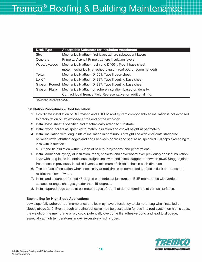
The following chart describes the Tremco approved substrate preparation and insulation attachment based onroof deck type.
Deck Type Acceptable Substrate for Insulation AttachmentSteel Mechanically attach first layer; adhere subsequent layers Concrete Prime w/ Asphalt Primer; adhere insulation layers Wood/plywood Mechanically attach rosin and D4601, Type II base sheet
(note: mechanically attached gypsum roof board recommended)Tectum Mechanically attach D4601, Type II base sheetLWIC* Mechanically attach D4897, Type II venting base sheetGypsum Poured Mechanically attach D4897, Type II venting base sheetGypsum Plank Mechanically attach or adhere insulation, based on density.
Contact local Tremco Field Representative for additional info. *Lightweight Insulating Concrete
Installation Procedures – Roof Insulation1. Coordinate installation of BURmastic and THERM roof system components so insulation is not exposed
to precipitation or left exposed at the end of the workday.2. Install base sheet if specified and mechanically attach to substrate.3. Install wood nailers as specified to match insulation and cricket height at perimeters. 4. Install insulation with long joints of insulation in continuous straight line with end joints staggered
between rows, abutting edges and ends between boards and secure as specified. Fill gaps exceeding ¼ inch with insulation. a. Cut and fit insulation within ¼ inch of nailers, projections, and penetrations.
5. Install additional layer(s) of insulation, taper, crickets, and coverboard over previously applied insulation layer with long joints in continuous straight lines with end joints staggered between rows. Stagger joints from those in previously installed layer(s) a minimum of six (6) inches in each direction.
6. Trim surface of insulation where necessary at roof drains so completed surface is flush and does not restrict the flow of water.
7. Install and secure preformed 45-degree cant strips at junctures of BUR membranes with vertical surfaces or angle changes greater than 45-degrees.
8. Install tapered edge strips at perimeter edges of roof that do not terminate at vertical surfaces.
Backnailing for High Slope ApplicationsLow slope fully adhered roof membranes or plies may have a tendency to slump or sag when installed onslopes above 2:12. Even though a roofing adhesive may be acceptable for use in a roof system on high slopes,the weight of the membrane or ply could potentially overcome the adhesive bond and lead to slippage,especially at high temperatures and/or excessively high slopes.
Minimize the potential for membrane slippage on high slopes:• Run the roof membrane in the same direction as the slope (parallel to the slope, not perpendicular to the
slope). Topnail the roof membrane at the peak of the slope and cover the fasteners with a cap ply. • Certain membrane reinforcements have sufficient strength to allow for topnailing so one can avoid
nailing in the middle of the membrane run. • Plan the membrane installation to take advantage of the full length of the membrane. Avoid end laps in
the middle of a run from peak to valley (or eave). When an end lap must occur, make sure it aligns over an insulation stop so the new ply can be nailed.
• Be aware of issues that may occur with adhesives. For example, softening point fallback can occur when hot asphalt is overheated in the kettle for extended periods of time. Fallback can lead to slippage issues of roofing plies and membranes which are adhered in hot asphalt that has been affected by this condition.
Backnailing for roof slopes between 2:12 (16.6%) and 3:12 (25%):• Mechanically attach wood blocking as an insulation stop to the deck 20’ (6m) on center perpendicular to
the slope.• Apply roof membrane parallel to the slope• During application, backnail each roofing ply to the wood blocking staggered 3 inch (75 mm) on center
on the back edge of the ply (the section covered by the overlapping ply). • Fasteners shall be covered by a minimum of two plies.
Backnailing for roof slopes of 3:12 (25%) and greater:• Mechanically attach wood blocking to the deck as an insulation stop 4’ (1220 mm) on center
perpendicular to the slope.• Apply roof membrane parallel to the slope.• During application, backnail each roofing ply to the wood blocking staggered 3 inch (75 mm) on center
on the back edge of the ply (the section covered by the overlapping ply).• Fasteners shall be covered by a minimum of two plies.
The purpose of a roofing pump is totransfer a cold applied adhesive orcoating to a roof and raise its pressure forspray application. There are two commontypes of pump systems used for roofingapplications: pneumatic (air driven) andhydraulic (fluid driven).
Pneumatic (Air Driven) Pump Systems A Pneumatic pump consists of two mainparts, the air motor and the lowerdisplacement pump. In addition, an aircompressor is required to operate apneumatic pump. The following chartprovides basic specifications forpneumatic roofing pump systems:
Pneumatic Pump & Air Compressor Specifications for Spraying POWERply Standard Cold Adhesive or BURmastic AdhesiveMinimum Pump Ratio 22:1Typical Pump/Compressor Air Pressure Output 90 to 120 psiPump Rated Flow Rate 3 GPM (gallon per minute) minimum Compressor Air Volume Delivery @ 100 psi 185 CFM minimum
The air motor and compressed air are used to operate the lower displacement pump, which draws the liquidfrom the container and raises the pressure of this material so it can be sprayed.
The pump ratio of a pneumatic pump is the relationship of the material pressure developed by the pump to theair inlet pressure. For example, a 22: 1 ratio pump running at 100 psi air pressure will develop 2,200 psi ofmaterial pressure at the outlet of the pump (22 X 100 psi = 2,200 psi).
The pump must be able to develop and sustain sufficient material pressure and flow rate within the materialhose to provide a full spray pattern. If the spray pressure is too low, the material will only pulse or streamthrough the spray tip. If the flow rate is too low, the material will sputter/starve at the spray tip. So a properlysized pump must be selected for use to for not only the product being sprayed, but for the delivery raterequired of the type of application.
The pump tube must be fully immersed in the material being pumped. The use of siphon tubes or extensionhoses to extend the length of the pump tube may restrict the flow of material into the pump tube. These types
of extensions should not be used unless otherwise designed or recommended by the pump equipmentsupplier.
Air Compressor The purpose of the air compressor is to provide the required volume of air at a specified pressure for theefficient operation of the pump.
These values provided in the previous chart are recommendations for the use of a spraying system consistingof one pneumatic pump. A typical pneumatic roofing pump requires approximately 110 CFM to operateefficiently. When running two or more pneumatic pumps, an air compressor which can deliver a greater volumeof air must be used. Two pumps will double the volume of air which is required for proper operation.
A pump may seem to operate on a lower than recommended air volume or air pressure. However, at theselower air volumes or air pressures, the pump will not be operating at its designed efficiency levels. This willresult in a reduced material flow rate and reduced spray pressure. The pump will cycle slowly, if it even cyclesat all.
Contact the manufacturer of the pump for more information on the minimum air volume required for theefficient operation of your pneumatic pump.
Air Compressor Components -Air Filter, Lubricator, Regulator & Shutoff Valve The use of an air filter unit is recommended in order to remove foreign particles and reduce moisture in the airsupply.
The use of an air lubricator may help to smooth the movement and extend the life of the air motor of the pumpby applying a measured amount of lubricant into the air supply. A light weight misting oil is typically used in anair lubricator. Some air motors do not require lubrication and may in fact be damaged by this procedure.Contact your pump manufacturer for specific recommendations.
The use of an air regulator allows for precise control of the air pressure into the pump.
An air shutoff valve is highly recommended for all pneumatic pumps. This will allow for the immediate oremergency shut-offs of the pump by closing the air line.
All of the above described air components must be designed and rated for use under the maximumtemperatures, maximum air pressures, and maximum airflow volumes (185 CFM) which the air compressor willprovide. Consult the manufacturer of the air compressor, pump, or air components for more specificrecommendations.
Air Hose Air Hose used to connect the compressor to the pneumatic pump should be heavy duty and reinforced towithstand pressures of at least 200 psi.
Minimum ID (inside diameter) required will typically be 3/4", using either Sleeve Type Air Coupler (QuickConnect) assemblies or Chicago Style Fittings for connecting components and sections.
Hydraulic (Fluid Driven) Pump Systems A Hydraulic pump consists of two parts, the fluid motor and the displacement pump. This pump operatesalong the same basic principle as pneumatic pumps, except that hydraulic fluid is used to operate the fluidmotor rather than compressed air. The following chart describes the minimum recommendations for ahydraulic roof pump spraying system:Hydraulic Pump Specifications for Spraying POWERply Standard Cold Adhesive and BURmastic AdhesiveMinimum Output Material Pressure 2,200 psiFlow Rate (Delivery) 3.0 GPM (gallons per minute, minimum)Size of Material Outlet Fitting ¾” NPT minimum
Hydraulic pumps are rated by the maximum material output pressure, not by pump ratio.
A hydraulic pump operates by circulating hydraulic fluid through the fluid motor at pressures in the range of800to 1 ,200 psi. This high pressure fluid operates a piston in the fluid motor. The piston's energy is transferred tothe displacement pump. This in turn raises the pressure of the material, causing it to be pumped and sprayed.
Most hydraulic pumps used in the roofing industry to spray apply BURmastic are self contained units. Thesepump units contain a gasoline engine (typical 18 HP) to drive the hydraulic fluid to the material pump. Thepump unit is mounted on a two wheel cart frame, making it extremely portable. Long lengths of material hosescan be eliminated, since these pumps can be brought almost to the point of application on the roof.
The pump tube must be fully immersed in the material being pumped. The use of siphon tubes or extensionhoses to extend the length of the pump tube may restrict the flow ofmaterial into the pump tube. These typesof extensions should not be used unless otherwise approved by Tremco.
Comparison of Hydraulic and Pneumatic Pumps A hydraulic pump system has better energy transfer efficiency compared to a compressed air system. Inaddition, a hydraulic system will operate without water condensation or icing problems in cold weatherbecause there is no air exhaust from a hydraulic pump system. Hydraulic pumping units are typically selfcontained, consisting of a gas driven hydraulic motor and the displacement pump on a portable cart.
Disadvantages of a hydraulic system include dependence on the hydraulic oil, which must be properlymaintained in order to be free of contamination, to keep fluids at proper levels, and to operate within theproper temperature range.
A pneumatic pump system requires a separate air source to operate the material pump. A 185 CFM aircompressor is required to run a pneumatic pump. This type of compressor is typically mounted on a trailer tobe towed by a truck.
Pneumatic systems are subject to water condensation and icing in cold weather. Pneumatic pumps aretypically less expensive than hydraulic pumps. However, when the cost of the needed compressor isconsidered, the final system prices are comparable.
Heat Exchange Units A tube-fired, thermostatically controlled oil bath heat exchange unit is the only recommended method ofwarming bituminous adhesives such as POWERply Standard Cold Adhesive and BURmastic Adhesive forspray application. The following criteria help to describe the equipment and typical operating conditions of aheat exchange unit for bituminous roofing adhesives:
Specification for Heat Exchange Unitfor Bituminous Roofing AdhesivesPipe Coils Schedule 80, boiler grade minimumHeat Transfer Oil, temperature range 250° to 350°F
In a commercial heat exchange unit, the bituminous adhesive is pumped through pipe coils submerged in adouble walled, insulated container of heat transfer oil. The bituminous adhesive is warmed to an outputtemperature of 90° to l00°F, depending on the temperature of the surrounding heat transfer oil.
Follow all operating and safety procedures per the manufacturer of the heat exchange unit.
Material Hoses - (SAE J517 100 Series, Type AT) A high pressure, hydraulic hose conforming to SAE J517 100 Series, Type AT must be used as a material linefor POWERply Standard Cold Adhesive and BURmastic Adhesive in all pressurized transfers from the pump tothe spray wand.
This type of material hose utilizes synthetic rubber in both the tube and cover material. Depending on thepump output spray pressure range, the specified hydraulic hose will contain one or more braids of wirereinforcement. Select the material hose so that its designed working pressure is equal to, or exceeds themaximum material output delivery pressure.
The material hose must be approved for use with fluids containing petroleum and paint solvents. The specifiedservice temperature range is from -40° to 200°F.
To achieve a good material spray pattern, it is important to have sufficient material pressure at the spray tip.However, material pressure drops off steadily as the material hose length is increased. Therefore, it is veryimportant to keep the material hose length to a minimum in order to maintain proper material pressure at thespray tip.
The following reference chart relates the hose diameter and working pressure rating to the SAE spec for aparticular fluid transfer hose:
Typically, a 22: 1 ratio pump can be used to spray material through 200' to 300' of standard 3/4" ID (InsideDiameter) material hose with 70°F material and air temperatures. By using a Heat Exchange Unit and a higheroutput pressure pump, longer lengths of material hose, up to 500', may potentially be used.
For pumping over long distances, always use a 1" ID material hose between the pump and the Heat ExchangeUnit. Next, use a large diameter hose (1" ID) material hose for as long a distance as possible to reduce thepressure drop through the hose. Then, using a reducing coupler, connect a smaller sized material hose to thespray wand for the last 15 - 20'. This will make the line easier to handle for the sprayer.
Inspect hoses regularly to assure safe spray operations. To prevent material leakage in case a hose bursts,thread the pressurized material line through a larger diameter hose (an old fire hose.) Always protect sensitiveor difficult to clean building features from accidental leaks.
Material Hose Connections The threaded hose connections should be constructed of a non-corrosive metal. Materials such as Brass,Stainless Steel w/ Zinc plating, or Steel w/ Chrome plating should be used because of their corrosionresistance. Aluminum fittings should not be used since they do not have the long term strength and durabilityneeded in a threaded connection which will be frequently loosened and tightened by wrench.
It is recommended to set up the material hoses with threaded male fittings and use female swivel fittings toconnect the sections of hose.
Quick connects are not recommended for material hoses since they are typic all y not rated for high pressureapplications. However, they are commonly used for air connections.
Spray Wands POWERply Standard Cold Adhesive and BURmastic Adhesive must be applied using airless pump andspraying systems. Using an air-assisted spray system would lead to uncontrollable overspray and poor controlof coverage rates.
Airless spray wands are availablein two general types, a pole gunor a trigger spray wand.
A pole gun utilizes a threadedsection of Schedule 80 pipe witha ball valve on one end and thespray tip on the other. One of theends is typically curved to directthe spray flow onto the roof.
A trigger spray wand utilizes asafety hand lever to control thespray flow. Trigger spray wands
can be much easier to handle than a full sized pole gun, however, the smaller 1.0. of the pipe leads to lowerflow rates. This may slow down a spray application, especially during the application of flood coats.
Valve Types When using a pole gun, a full port ball valve is needed to act as an on/offvalve for material flow. A full port ballvalve allows the ball to open up to the maximum inner diameter of the material line. Standard ball valvesreduce the inner diameter of the valve at the ball and create a flow restriction and are not recommended forthat reason. The pressure rating on all valves must be matched to the maximum output pressure of the pump.
Ball valves are typically sealed with Teflon packing gaskets. It is important to run the valve in the fully openedposition, since a partially opened position will allow high pressure material to flow across the packing surface.This will lead to premature packing failure. Reinforced Teflon packings are recommended rather than virginTeflon packings.
Reinforced Teflon (modified with glass fiber) is more wear resistant. Reinforced Teflon tends to be off-white incolor, while virgin Teflon is brilliant white.
Metal on Metal spray valves have been developed to reduce the dependency on packings, and the relatedmaintenance. These metal on metal valves are made of hardened steel, making them extremely wear resistant.
Spray Tips A heavy duty, reversible spray tip should be used for the most efficient spray application of POWERplyStandard Cold Adhesive and BURmastic Adhesive. The reversible tip allows for minor clogging to be quicklycleared with minimal down time.
The spray tip nozzle should provide what is known as a flat spray fan pattern. In addition, the seals andgaskets used within the spray nozzle must be compatible with solvents in the material being sprayed.
Follow manufacturers recommendations for the safe use and maintenance of spray tips.
Spray Tips Specifications for POWERply Standard Cold AdhesiveOrifice Size Range 0.052" to 0.072"Spray Fan Angle 45° to 65°Spray Fan Width (at 1 foot) Approx 8" to 14"Gasket Type Teflon or Viton
Squeegee Application A neoprene rubber squeegee is recommended for manual application of POWERply Standard Cold Adhesiveand BURmastic Adhesive SF. A serrated blade, with jagged rubber tines (teeth) will allow the adhesive to beevenly spread across the substrate.
By selecting the proper height of the notching on the blade, the coverage rate can be easily controlled. Inaddition, the pressure exerted on the blade helps to control coverage rates. Serration notches of 3/16" to 1/4"are sufficient to allow for the application of adhesive at the proper coverage rate. However, good roofingpractice dictates that an area should be marked off to confirm the proper material coverage rate. Alternately,use a squeegee designated 40 mil or 45 mil for interply application and 75 or 90 mil for flood coat application.
Squeegee blades must be replaced when the tines become rounded and worn. Wipe the squeegee bladeclean using Mineral Spirits after the application. Soaking the rubber blades in solvent will cause them to swelland render them useless.
BURMAST IC APPL ICAT ION INSTRUCT IONS Cut BURmastic Glass Ply and BURmastic Glass Ply 28 lb. into 18 ft. lengths max. and allow to relax aminimum of 30 minutes at 55° F or above and a minimum 60 minutes below 55° F. This allows the plies toexpand thermally before the application and can significantly reduce the potential for ridges and fishmouths.
• Do not stack plies more than 1” high as that prevents warming of all plies• Plies cut into sections are then “flopped” or “flown” into the BURmastic Adhesive
The BURmastic Composite Ply line is designed with a trilaminate reinforcement that allows it to be appliedcontinuously from the roll and does not need to be cut and relaxed prior to application.
Embed each ply in a uniform and continuous layer of BURmastic Adhesive. Ply shall never touch ply.
Firmly broom plies from the unfinished side of the roof. A firm brooming assures proper contact with theBURmastic Adhesive and reduces the potential for interplay voids. Avoid walking on freshly installed plies.
Overlap previous day’s work a minimum of 24”.
End laps should extend a minimum 6” onto previous sheet and should be staggered a minimum 36” fromprevious run.
The roofing application should be staged so that all work is conducted on the unfinished side of the roof sothat traffic on the completed roof is minimized or eliminated. This is important for several reasons:
• Traffic on newly applied plies can displace adhesive leaving voids in the system• Newly applied plies can be displaced by traffic leading to wrinkling and damage of the system• BURmastic Adhesive should bleed-out at side and end laps and can be easily picked up on workers
shoes. Sticky shoes will pull on the roof and can damage the freshly applied plies.
Base Sheet Installation:Install lapped base sheet course, extending sheet over and terminating beyond cants.
Adhere the base sheet to substrate in uniform coating of cold-applied adhesive.
Ply Sheet Installation:Install ply sheets starting at low point of roofing and shingle in direction to shed water.
Align ply sheets without stretching.
Shingle side laps of ply sheets uniformly to achieve required number of plies throughout thickness of roofingmembrane.
Extend ply sheets over and terminate beyond cants.
Embed each ply sheet in cold-applied membrane adhesive applied at specified coverage rate to form auniform membrane without ply sheets touching.
APPL ICAT ION INSTRUCT IONS - HOT BUR :Install lapped base sheet course, extending sheet over and terminating beyond cants.
Adhere to substrate in a solid mopping of hot roofing asphalt.
Ply Sheet Installation:Install ply sheets starting at low point of roofing and shingle in direction to shed water
Align ply sheets without stretching.
Shingle side laps of ply sheets uniformly to achieve required number of plies throughout thickness of roofingmembrane.
Extend ply sheets over and terminate beyond cants.Embed each ply sheet in a solid mopping of hot roofingasphalt applied at specified coverage rate to form a uniform membrane without ply sheets touching.
FLASH INGS MEMBRANES AND ADHES IVES Flashing Membrane Approved Adhesive DescriptionHypalon Elastomeric Sheeting Sheeting Bond (Black or White) Black/white 45 mil polyester reinforced
POLYroof SF Hypalon membraneTRA Elastomeric Sheeting Sheeting Bond (Black or White) A black 45 mil flashing membrane
POLYroof SF compounded from a blend of EPDM and THERMastic Adhesive SBR thermoset polymers reinforced with THERMastic 80 Adhesive a polyester scrim
TPA Flashing Sheeting Bond (White) A white 45 mil thermoplastic tri-polymer TPA Bonding Adhesive alloy flashing membrane
POWERply MB (w/backer sheet) Sheeting Bond (Black) SBS modified, granule surfaced modified-ELS bitumen membranes reinforced with Brush Grade Mastic fiberglass, polyester, or polyester/POLYroof SF fiberglass compositeHot-Melt Asphalt Adhesives
Multi-Ply Asphalt ELS Min 2 plies of ASTM D4601 fully coated Brush Grade mastic asphalt base/ply sheetsHot-Melt Asphalt Adhesives
General Requirements:
Base flashings shall extend onto the roof a minimum of 6” beyond the toe of the cant and a minimum 8” above the surface of the roof.
Flashing membranes and exposed mastics may be surfaced with a reflective coating to extend service life.
Leading edge of base flashings is
sealed with a minimum 3-courseapplication of roofing mastic and reinforcing membrane.
Flashing AdhesivesExcessive adhesive application can lead to slippage or blistering of theflashing membrane.
Hypalon flashings shall be adhered with Sheeting Bond or POLYroof SF only.
Tremco® Roofing & Building Maintenance
22
TRA flashings may be adhered with Sheeting Bond, POLYroof SF, or SEBS modified hot melts (THERMastic orTHERMastic 80). Do not adhere with ASTM D312 Type III or IV non-modified asphalt.
Sheeting Bond shall be allowed 10-15 minutes open time for solvents to flash-off. Install Elastomeric flashingsheets promptly after open time. Do not exceed open time or adhesive may skin-over and not bond properly.
Flashing Installation – GeneralFlashing a roof requires traffic on the new roof installation to complete the flashings. On a THERM hot-appliedBUR the roof must be allowed to cool before the flashings are completed.
Protect POWERply roof membrane during the installation of the flashings. Plywood or insulation boards overthe roof membrane will spread loads over the surface and prevent point load damage to the membrane.
Temporary flashing may be installed during the membrane application with permanent flashings installed afterthe cold adhesive has set and is less susceptible to displacement and damage.
Elastomeric flashings may be pre-hung and dropped into place to reduce the amount of traffic on the newlyinstalled roof.
Install base flashing over cant strips and other sloping and vertical surfaces, at roof edges, and at penetrationsthrough roof, and adhere to substrate.
Prime substrate with specified asphalt primer when adhering flashings in asphalt mastics or hot asphaltadhesives.
Backer Sheet Application: Adhere backer sheet to substrate in cold-applied flashing adhesive or hot asphaltadhesive.
Flashing Sheet Application: Adhere flashing sheet to backer sheet or substrate in specified cold-applied or hot-melt adhesive.
Extend base flashing up walls or parapets a minimum of 8 inches above built-up roofing and 6 inches ontofield of built-up roofing.
Mechanically fasten top of base flashing securely at terminations and perimeter of roofing.
Seal top termination of base flashing with a metal termination bar.Install stripping where metal flanges andedgings are set on roof membrane.
Flashing-Sheet Stripping: Install flashing-sheet stripping in a continuous layer of flashing sheet adhesive, andextend onto roofing membrane.
Roof Drains: Set lead or copper flashing in bed of asphalt mastic on completed built-up roofing. Cover metalflashing with stripping and extend a minimum of 6 inches beyond edge of metal flashing onto field of built-uproofing. Clamp built-up roofing, metal flashing, and stripping into roof-drain clamping ring.
Hypalon Flashing Installation:Hypalon Membrane InstallationPlan installation of Hypalon flashings so that the sheet extends 6” from the base of the cant onto the surface ofthe roof system.
Remove embedded gravel, dirt, dust, rotted felt, and foreign matter. Priming is recommended.Apply Sheeting Bond in a uniform and continuous application 1/16” thick to prepared area. Leave SheetingBond exposed 15 minutes minimum before membrane application. Adjust open time depending on ambientconditions.
Adhere Hypalon Elastomeric Sheeting in Sheeting Bond without wrinkles or voids. Using a steel hand roller,apply consistent pressure to achieve full adhesion of the sheet to the flashing substrate. Sheeting must fullyconform to all angle changes, with no bridging or voids.
Vertical seams must be a minimum 4”. Strip in base of flashing membrane to roof with BURmesh reinforcingfabric embedded in a base course of Sheeting Bond and covered with POLYroof LV, POLYroof SF, or ELS.Exposed mastics used to strip in flashings may be covered with a reflective coating to extend service life.
Secure top edge of Hypalon flashing to wall by nailing on 6'' (152mm) centers or by using a termination barfastened on 8'' (203mm) centers.
Extend flood coat or surfacing emulsion over stripping plies and Hypalon Elastomeric Sheeting to the base ofthe cant.
Hypalon Seam Installation with Sheeting BondWipe min. 4” wide lap seams with Tremco approved solvent, such as Toluene.
Fabricate laps with Sheeting Bond applied to one surface at 30-35 ft2 per gallon and allow approx. 15 minutesopen time for the solvents to flash off. Adjust open time depending on ambient conditions.
Join laps by pressing across fabricated lap seam; remove wrinkles/entrapped air; ensure positive contact. Rollacross laps with steel roller to ensure positive contact.
Strip in vertical seams and base of flashing membrane to roof with BURmesh reinforcing fabric embedded in abase course of Sheeting Bond and covered with POLYroof LV or POLYroof SF. Allow the Sheeting Bond todevelop a firm set prior to the application of the POLYroof LV or SF.
TRA Flashing InstallationSurface Preparation: Remove all dirt, dust, and other loose debris from the roof. Spud back all embeddedgravel from the area. Area should be prepared down to a clean, sound, dry base.
Plan installation of TRA Elastomeric Sheeting so flashing height is between 8'' and 12'' off the roof membraneand the sheeting extends 6'' (152mm) from the base of the cant onto the roof system.
All vertical end laps shall be overlapped a minimum 4''.
Hot (SEBS Modified Asphalt) Application:For hot application, apply THERMastic or THERMastic 80 SEBS-modified hot-melt adhesive to the area in auniform and continuous mopping at a coverage rate of 25 lbs. /SQ. Do not adhere TRA in ASTM D312 Type IIIor IV asphalt.
Immediately embed TRA Elastomeric Sheeting in the hot application of approved adhesive.
Apply consistent pressure to the TRA Elastomeric Sheeting to achieve full adhesion of the sheet to the flashingsubstrate. Sheeting must fully conform to all angle changes, with no bridging or voids.
Secure top edge of TRA Elastomeric Sheeting to wall by nailing on 6'' (152mm) centers or by using atermination bar fastened on 8'' (203mm) centers.
Strip in base of flashing to roof system using a three course application of approved adhesive and6''PolyTHERM roofing felt. As an alternate, strip in base of flashing with a five course stripping of approvedadhesive and THERMglass Roofing Ply.
Strip in vertical flashing laps with BURmesh set in Sheeting Bond, followed by a top course of POLYroof LV orPOLYroof SF.
Exposed mastics used to strip in flashings may be covered with a reflective coating to extend service life.
Cold Adhesive Application:For cold application, apply Sheeting Bond or POLYroof SF to the area in a uniform and continuous layer at acoverage rate of approx. 15 ft2/gal.
Leave Sheeting Bond exposed 15 minutes minimum prior to membrane application. Adjust open timedepending on ambient conditions.
Adhere TRA Elastomeric Sheeting in flashing adhesive. Apply consistent pressure to achieve full adhesion ofthe sheet to the flashing substrate. Sheeting must fully conform to all angle changes, with no bridging or voids.
Secure top edge of TRA Elastomeric Sheeting to wall by nailing on 6'' (152mm) centers or by using atermination bar fastened on 8'' (203mm) centers.
Strip in base of flashing to roof system and vertical flashing laps, using a three course application ofBURmeshset in Sheeting Bond, followed by POLYroof LV or POLYroof SF. Exposed mastics may be covered with areflective coating to extend service life.
COVERAGE RATES:THERMastic and THERMastic 80: 25 lbs. /SQ. Flashing Adhesive: 15 sq. ft. /gal Coverage rates will vary depending on ambient temperature and surfaceconditions.
Surfacing: TRA Elastomeric Sheeting may be coated with a reflective roof coating. Two coats arerecommended for best coverage. A STAIN-BLOCKING COATING OR PRIMER IS REQUIRED PRIOR TOAPPLYING WATERBASED ACRYLIC COATINGS TO TRA ELASTOMERIC SHEETING.
TPA Flashing Installation: Application as Roof Flashings for MB Systems:Plan installation of TPA Flashing Membrane so flashing extends 6” from the base of the cant onto the roofsystem. All vertical overlaps must be 4” minimum.
Remove embedded gravel, dirt, dust, deteriorated felts, and other loose debris from the roof.
Spud back all embedded gravel from the area to receive the flashing and stripping. Area should be prepareddown to a clean, sound, dry base.
Apply adhesive to prepared area. Trowel apply White Sheeting Bond in a uniform and continuous application1/16” thick to prepared flashing substrate. Allow Sheeting Bond to remain exposed for 15 minutes prior toinstalling TPA Flashing Membrane into this adhesive. Adjust open time depending on ambient conditions.
Alternately, TPA Bonding Adhesive LV may be used to adhere TPA Flashings to the wall and out onto the roofmembrane. Apply adhesive to the back of the TPA Flashing and onto the substrate, in a contact cementapplication.
Adhere TPA Flashing Membrane in adhesive, using care to avoid wrinkles and voids. Use a steel hand roller toapply consistent pressure to achieve full adhesion of the membrane to the flashing substrate. TPA FlashingMembrane must fully conform to all angle changes, with no bridging or voids.
Overlap vertical flashing seams a minimum of 4”. Heat weld vertical overlap seams, minimum width of 2”. Priorto hot air heat welding, make sure lap interface materials are clean of dirt and moisture.
Seal inside and outside corners using Non-Reinforced TPA Membrane or TPA Inside/ Outside Corners appliedby hot air heat welding.
Strip in base of TPA Flashing Membrane with a first course of Rock-It Adhesive followed by a stripping ply ofBURmesh or SRC Polyester Reinforcing Fabric. Top dress these stripping courses with specified roofsurfacing, such as the Rock-It Surfacing System, Flood and Gravel, TremLastic SP and granules, or ICECoating.
No additional coatings are necessary for TPA Flashing Membrane. If a protective coating is required, specialsurface preparation may be necessary. Tremco SP Primer is required prior to application of ICE Coating,Tremlite Coating, and Polarcote FR. Allow TPA Flashing Membrane to be exposed to the elements for 30 daysminimum prior to application of the SRC Coating System.
POWERply MB Flashing InstallationSurface Preparation: Remove all dirt, dust, and other loose debris from the roof. Spud back all embeddedgravel from the area. Area should be prepared down to a clean, sound, dry base.
Plan installation of POWERply MB membrane so flashing height is between 8'' and 12'' off the roof membraneand the sheeting extends 6'' (152mm) from the base of the cant onto the roof system.
All vertical end laps shall be overlapped a minimum 4''.
A fully-coated backer sheet must be installed prior to the application of POWERply MB flashing.
POWERply MB Flashing which are up to 12” in flashing height may be installed in 10’ runs. POWERply MBFlashings in excess of 12” in height must be installed in 3’ (1 meter) roll widths.
Hot Asphalt Application:For hot application, apply approved hot-melt adhesive to the substrate area in a uniform and continuousmopping at a coverage rate of 25 lbs. /SQ.
Immediately embed the backer sheet or POWERply membrane in the fluid hot adhesive. Apply consistentpressure to achieve full adhesion of the sheet to the flashing substrate. Sheeting must fully conform to all anglechanges, with no bridging or voids.
Secure top edge of POWERply membrane to wall by nailing on 6'' (152mm) centers or by using a terminationbar fastened on 8'' (203mm) centers.
Strip in base of flashing to roof system using a three course application of approved adhesive and6''PolyTHERM roofing felt or a five course application of approved adhesive and THERMglass Roofing Ply.
As an alternate, Strip in base of flashing to roof system using a minimum three course application of ELSmastic and BURmesh.
Strip in vertical flashing laps with a minimum 3-course application of BURmesh set in ELS, Brush GradeMastic, POLYroof LV or POLYroof SF. Exposed mastics may be covered with a reflective coating to extendservice life.
Cold Adhesive Application:For cold application, apply ELS, Brush Grade Mastic, Sheeting Bond (Black) or POLYroof SF to the area in auniform and continuous layer at a coverage rate of approx. 15 ft2/gal.
Leave Sheeting Bond exposed 15 minutes minimum prior to membrane application. Adjust open timedepending on ambient conditions.
Adhere the backer sheet and POWERply MB in flashing adhesive. Apply consistent pressure to achieve fulladhesion of the sheet to the flashing substrate. Sheeting must fully conform to all angle changes, with nobridging or voids.
Secure top edge of POWERply MB membrane to wall by nailing on 6'' (152mm) centers or by using atermination bar fastened on 8'' (203mm) centers.
Strip in base of flashing to roof system and vertical flashing laps, using a three course application ofBURmeshset in ELS, Brush Grade Mastic, POLYroof LV or POLYroof SF.
Stripping of POWERply MB flashing membrane may be eliminated only when POWERply MB Flashing isheat welded to the POWERply MB roof membrane substrate.
Surfacing: POWERply MB flashings may be coated with a reflective roof coating.
Multi-Ply Asphalt FlashingsMulti-ply asphalt flashings consist of 2 plies of a fully-coated base/ply sheet such as BURmastic CompositePly HT or POWERply Base Sheet adhered with approved hot or cold applied adhesive. Type IV and VIfiberglass felts are not approved for use in multi-ply asphalt flashing systems.
Surface Preparation: Remove all dirt, dust, and other loose debris from the roof. Spud back all embeddedgravel from the area. Area should be prepared down to a clean, sound, dry base.
Plan installation of multi-ply asphalt flashings so that flashing height is between 8'' and 12'' off the roofmembrane and the sheeting extends 6'' (152mm) from the base of the cant onto the roof system.
All vertical laps shall be overlapped a minimum 4''.
Hot Asphalt Application:For hot application, apply approved hot-melt adhesive to the substrate area in a uniform and continuousmopping at a coverage rate of 25 lbs. /SQ.
Immediately embed the backer sheet and flashing membrane in the fluid hot adhesive. Apply consistentpressure to achieve full adhesion of the sheet to the flashing substrate. Sheeting must fully conform to all anglechanges, with no bridging or voids.
Secure top edge of multi-ply flashing to wall by nailing on 6'' (152mm) centers or by using a termination barfastened on 8'' (203mm) centers.
Strip in base of flashing to roof system using a three course application of approved adhesive and6''PolyTHERM roofing felt or a five course application of approved adhesive and THERMglass Roofing Ply.
As an alternate, Strip in base of flashing to roof system using a minimum three course application of ELSmastic and BURmesh.
Strip in vertical flashing laps with a minimum 3-course application of BURmesh set in ELS, Brush GradeMastic, POLYroof LV or POLYroof SF. Exposed mastics may be covered with a reflective coating to extendservice life.
Cold Adhesive Application:For cold application, apply ELS, Brush Grade Mastic, Sheeting Bond (Black) or POLYroof SF to the area in auniform and continuous layer at a coverage rate of approx. 15 ft2/gal.
Leave Sheeting Bond exposed 15 minutes minimum prior to membrane application. Adjust open timedepending on ambient conditions.
Adhere the backer sheet and flashing membrane in flashing adhesive. Apply consistent pressure to achieve fulladhesion of the sheet to the flashing substrate. Sheeting must fully conform to all angle changes, with nobridging or voids.
Secure top edge of multi-ply flashing to wall by nailing on 6'' (152mm) centers or by using a termination barfastened on 8'' (203mm) centers.
Strip in base of flashing to roof system and vertical flashing laps, using a three course application ofBURmeshset in ELS, Brush Grade Mastic, POLYroof LV or POLYroof SF.
Surfacing: Multi-ply asphalt flashings require the application of a reflective coating. Two coats are recommended for best coverage.