NAVY DEPARTMENT BUREAU OF ORDNANCE WASHINGTON 25, D. C. OP 1140 CHANGE 1 9 Karch 1949 To all holders of ORDNANCE PAlIPHLBT 1140 iasert change; write on cover 'Change 1 inserted' Approved by The Chief of the Bureau of -- -- tl 1 "":'"" J. \ -==-n (1 Pale chIef Of Bureau ___ Pale 1 ORDNANCE PAlIPHLET 1140 18 changed as follows: BASIC FIRE CONTROL lIBeRANISMS .. • 1. Insert this change sheet between cover and title page. 2. Replaoe page 7 with new page 7 attached • 3. Insert section 7, pages 373 to 424, attaohed. 4. Cancel INDEX page 372; remove and destroy INDEX pages }73 through 378; cancel INDEX page 379. A corrected index has not been prepared. Delete numbers but retain distribution list (original page 380) and NOTES (original pages }81 through 384). DISTBIlroTIOll for ad.d1 tiQDal copies af Ordnance Pamphlet 1140 (CbaDge 1) .hould be au.bm1tted on Ba.lxo. 158, Stock 10m. and Publication. Bequi81 tien, through the Di.trict Publication. and Printin« Office by which addr ..... i. serviced. Standard Bavy Dhtribution Irist lfo. 56 (Part 1) and :ldlt1en lIo. 14 (Part 2) to Catalog of AotlTltle. of the BaTY. 2 copie. unle.. otherdse noted' 21; 22; 23; 24A,C,D,J:,F,II; 26J',II; 27A,C; 28A,:B,C,D,E,J; 29(5 cop. e.) A,H,J,K,L; 29:B,C,D,J:,K,Jl,Q,P; 30C; 32A,E,.,S,T,W.DD t BH,JJ; 38A,:B*,O*; A3(CNO); A6(:Bu8hips,:Bu.Aer,:BuOrd); :Bl,Q,(Arlington only}: J'2; J3,12,37, 60,75,76,83,84,87,95; J(25 copie.)9l; X5A,B,C,12; L(lO copie.)l; B20; BuOrd Special List XL. *Applicable Group. and Subgroup. 'lb.e above distribution li.t inclue. the following veueb of the acUTe and reserve fieet.. DDE, DDR, Dblt. OM ,,AD,AG,AO ,AR,A!lH •.ARL ,AS ,AV .AVP • PUC-III'-1-11-4' •
Transcript
NAVY DEPARTMENTBUREAU OF ORDNANCE
WASHINGTON 25, D. C.OP 1140 CHANGE 1
9 Karch 1949To all holders of ORDNANCE PAlIPHLBT 1140iasert change; write on cover 'Change 1 inserted'Approved by The Chief of the Bureau of Or~;,e -- -- tl
1"":'""J. \-==-n{~ (1 Pale1cil~g chIef Of Bureau
___ Pale 1
ORDNANCE PAlIPHLET 114018 changed as follows:
BASIC FIRE CONTROL lIBeRANISMS
..
•
1. Insert this change sheet between cover and title page.
2. Replaoe page 7 with new page 7 attached•
3. Insert section 7, pages 373 to 424, attaohed.
4. Cancel INDEX page 372; remove and destroy INDEX pages }73 through 378;cancel INDEX page 379. A corrected index has not been prepared. Delete~age numbers but retain distribution list (original page 380) and NOTES(original pages }81 through 384).
DISTBIlroTIOll
~que.ts for ad.d1 tiQDal copies af Ordnance Pamphlet 1140 (CbaDge 1).hould be au.bm1tted on Ba.lxo. 158, Stock 10m. and Publication.Bequi81tien, through the Di.trict Publication. and Printin« Officeby which addr..... i. serviced.
Standard Bavy Dhtribution Irist lfo. 56 (Part 1) and :ldlt1en lIo. 14(Part 2) to Catalog of AotlTltle. of the BaTY.
'lb.e above distribution li.t inclue. the following veueb of theacUTe and reserve fieet.. :BB.CV.CV:B,CVE,CVL~CA,CB,CL.CLAA,DD.
DDE, DDR, Dblt. OM ,,AD,AG,AO ,AR,A!lH•.ARL ,AS ,AV .AVP
•
PUC-III'-1-11-4'
•
•
'. '.
I ., ~. t ' ,
~06
ORDNANCE PAMPHLET 1140
B·ASICFIRE CONTROLMECHANISMS
SEPTEMBER 1944PROPERTY OF LIBRARY
•• S. NAVAL SCHOOL (GENERAL LINE)
1l40NTERE't, CALIFORNIA
This publication is RESTRICTED and will be handled in accord
ance with Article 76, United States Navy Regulations, 1920.
1
2
..
NAVY DEPARTMENT
BUREAU OF ORDNANCEWASHINGTON 25. D. C.
September 1944
RESTRICTED
ORDNANCE PAMPHLET 1140
BASIC FIRE CONTROL MECHANISMS
1. Ordnance Pamphlet 1140 explains the mechanicaland electromechanical basic mechanisms used by Ford InstrumentCompany and Arma Corporation in fire control equipment built forthe United States Navy. It is bound in loose-leaf form with provision for expansion in case it is desired to add material at alater date.
2. This publication is a basic text and reference book,providing a source of general information on the basic mechanismsof fire control equipment. It is considered that Ordnance Pamphlet1140 is a prerequisite to the study of any Ordnance Pamphlet on themechanical computing instruments for fire control equipment.
3. .Ordnance Pamphlet 1140 supersedes Ordnance Data1661, which should be destroyed.
4. This publication is RESTRICTED and should behandled in accordance with Article 76, U. S. Navy Regulations, 1920.
, JR.Rear Admiral, U. S. NavyChief of the Bureau of Ordnance
3
BASIC MECHANISMS
4
Prepared For
THE BUREAU OF ORDNANCE
by the
FORD INSTRUMENT COMPANY, INC.
long Island City, New York
OP 1140
SUMMARY: A SIMPLIFIED [COMPUTING NETWORK
102632
299310
PAGE
A SIMPLIFIED NETWORK
SETTING THE NETWORK
BASIC MECHANICS
BASIC MATHEMATICS
BASIC SETTING INFORMATION
TECHNICAL APPENDIX
DIFFERENTIALS
CAMS
MULTIPLIERS
COMPONENT SOLVERS
DISK INTEGRATORS
COMPONENT INTEGRATOR
NON·COMPUTING MECHANISMS
IN DE X
MAGNETISM AND- elECTRICITY
SIGNAL, lOCK, AND CLUTCH
TIME .OF FLIGHT SIGNAL MECHANISM
SERVO MOTORS
MOTOR REGULATOR
FOllOW·UP CONTROLS
SYNCHROS
SYNCHRO TRANSMITIERS AND RECEIVERS
[REFERENCE
BASIC INFORMATION
ELECTROMECHANICALUNITS
. MECHANICAL UNITS
QUI CK
•MECHANICAL UNITS
ELECTROMECHANICALUNITS [
DIFFERENTIALS
CAMS
RESOlVERS
INTEGRATORS
FOllOW·UP HEADS
TIME MOTOR GOVERNOR
5
BASIC MECHANISMS
FORD MECHANISMSBASIC INFORMATION Page
BASIC MECHANICS ..... 10
BASIC MATHEMATICS 26
BASIC SETTING INFORMATION 32
MECHANICAL UNITSDIFFERENTIALS 38
Bevel-gear type... 39Spur-gear type 45
CAMS.......... .. 46Flat type: Groove .. 47Flat type: Edge....................... 52Barrel type . 54How to set Cams 56
.cOMPONENT SOLVERS................... 86Cam type 87
Constant lead cam 93Computing cam 98Offset pin 104
Screw type . . 100Vector Solver 106How to set Component Solvers 108
DISK INTEGRATORS 114Wheel type 116Ball-and-Roller Type 117How to set Disk Integrator 134
COMPONENT INTEGRATOR 136How to set Component Integrator .. 142
NON· COMPUTING MECHANISMS .. 144Limit Stops 144Intermittent Drive 146Hand Cranks : 152Frictions ~ 156Vernier Clamp 160Detents 161Take-up Spring 161Dials..... . 162How to set the Intermittent Drive .. 164How to set Handle Frictions 166How to set Limit Stops 168
6
The r,e i sad eta i led ALP H ABE TIC A L' I N D EX 0 n p age 3 7 2
IN' R. 0 Due , IONThe basic mechanisms described in this book were especially developed over a period of about 30 years to do a highly specialized job.That job is to solve mechanically the mathematics for surface andanti-aircraft fire control. These basic mechanisms make the necessary computations to point the guns and set the fuzes to hit fastmoving targets with shells fired from the deck of a ship which ismoving, pitching, and rolling. To aim the guns correctly under theseconditions about 25 things must be taken into account all at thesame time. These include target speed, climb, and direction; targetrange, elevation, and bearing; own ship speed and course; wind speedand direction; pitch and roll; and initia~ shell velocity.
If the enemy were to announce six or eight hours beforehand justwhere the target would be at a particular instant and just how itwould be moving, a lightning mathematician would be able to calculate where to point the guns to hit it at that one instant. But, theresults would be good only for one instant.
Instead of going through the mathematical calculations necessaryto make each shot count, a ship might try to throw out enough exploding shells to hit the target almost by pure chance. That is, itmight throw out a barrage of shells and let the target fly into them.This type of fire is effective against some types of air attack, but it isfar from a satisfactory answer to the problem of aiming the guns.
What is needed is an instrument which will predict quickly andaccurately what will happen while the shell is in the air, computethe necessary corrections for the guns, and in addition continuouslycorrect the guns for the effects of pitch and roll of own ship. As soonas a target is picked up, this instrument must be able to solve the firecontrol problem in a few seconds and thereafter it must keep onsolving the problem continuously and accurately as own ship andtarget move in relation to each other.
At first it might seem that such an instrument would be far too complex for anyone but an engineer to understand, but that is not true.Actually it is a collection of standard mechanisms and parts assembled together inside a case. Each mechanism or part has a particular job to do in solving the fire control problem. This book isintended to explain what these mechanisms are and what each cando. By studying each unit in turn, learning what it can do and howit does it, and how it can be used with the other units, it is possibleto learn many of the fundamental things that one must know tooperate and maintain the Computers, Range Keepers and other instruments. These include:
Computer Mark 1, for the 5" guns, and certain others.Range Keeper Mark 10, for the 5" guns.Range Keeper Mark 8, for main battery guns.Computer Mark 3, stand-by for the Mark 8.Torpedo Data Computer Mark 3 and Mark 4.
_11I1i.
•
•
SECTION 1
BASIC I Fa Alia
A certain amount of basic information is necessary to understand fire control mechanisms. This information is summarized in the three chapters which make up this section.
1 The chapter, "Basic Mechanics," introduces a number ofm,echanical elements common to most of the mechanisms.These mechanical elements include gears, shafts, bearings and clamps. This chapter also explains several basicmechanical ideas such as "gear ratios," "shaft values" and"shaft positions."
2 "Basic Mathematics" briefly summarizes the mathematical operations which are more frequently used in firecontrol. This chapter does not try to teach mathematics,but assumes that the principles it reviews are alreadyfamiliar. Later explanations of the computing m~chanisms
will be based largely on these mathematical principles.
3 "Basic Setting Information" describes the more importantsetting tools and procedures commonly used in setting thevarious mechanisms. This chapter supplies the basic information which will be needed to understand the settinginstructions included with the description of each mechanism.
4 The basic information about magnetism and' electricityneeded for Section 3 on Electromechanical Units is furnished in the first chapter of that section.
Basic Mechanics""",.,.".Basic Mathematics ..Basic Setting Information
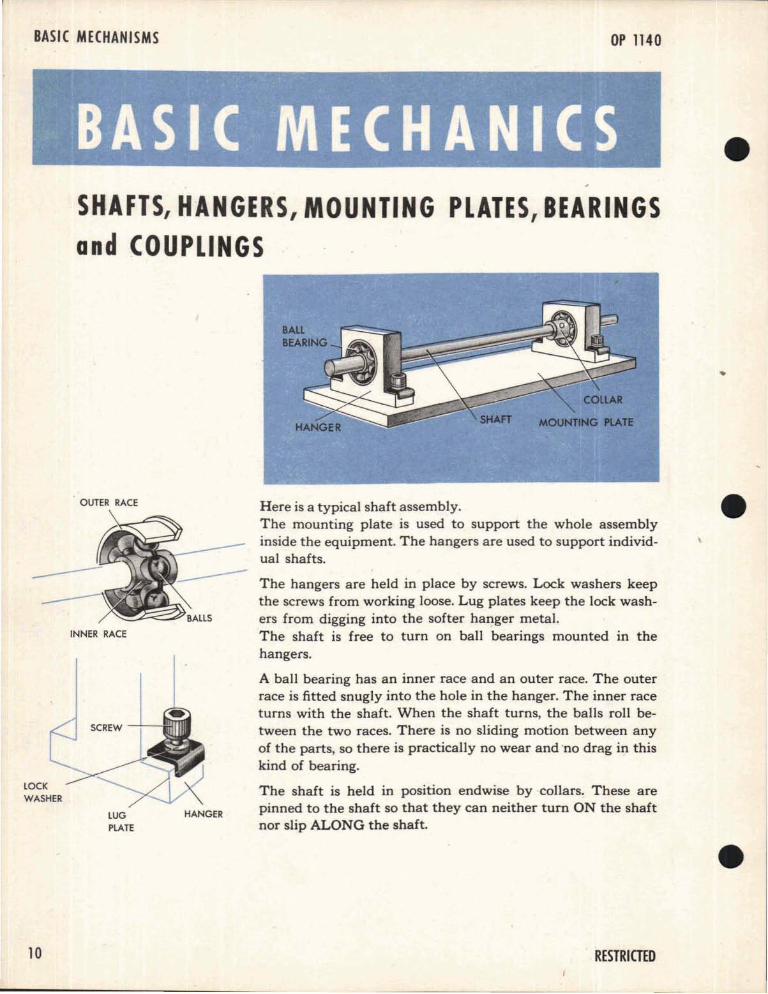
Here is a typical shaft assembly.The mounting plate is used to support the whole assemblyinside the equipment. The hangers are used to support individual shafts.
The hangers are held in place by screws. Lock washers keepthe screws from working loose. Lug plates keep the lock washers from digging into the softer ha~ger metal.The shaft is free to turn on ball bearings mounted in thehangers.
A ball bearing has an inner race and an outer race. The outerrace is fitted snugly into the hole in the hanger. The inner raceturns with the shaft. When the shaft turns, the balls roll between the two races. There is no sliding motion between anyof the parts, so there is practically no wear and 'no drag in thiskind of bearing.
The shaft is held in position endwise by collars. These arepinned to the shaft so that they can neither turn ON the shaftnor slip ALONG the shaft.
HANGERLUG
PLATE
OUTER RACE
INNER RACE
LOCK
WASHER
10 RESTRICTED
11
BASIC MECHANICS
CLAMPS
LOCKING SPRINGIS PUT INHERE
SHAFT
BENT WIRETO BE PUTTHROUGH lUGS
COILSPRING
LOCKINGSPRING
LUG \CENTER DISK
There are three principal devices used to join shafts end to end:
1 A sleeve coupling is used to join two closely aligned shaftsusually where an adjustment of the shaft relationship isnecessary. It consists of a sleeve over the ends of the twoshafts, with a clamp over tach end of the steeve.
The ends of the sleeve are slit so that the clamps can holdthe sleeve tightly on the shafts.
When the clamps are tight, the two shafts are held firmlytogether in the sleeve. and will turn as one.
2 An Oldham coupling is used to eliminate the necessity ofperfect alignment between two shafts. It is also used between two shafts that must be readily connected or· disconnected. Occasionally it is used as an expansion joint ina long shaft.
END DISKS AREPINNED TO SHAFTS
The Oldham coupling consists of a pair of disks pinned tothe ends of the shafts, and a third center disk, with lugs,which fits between the two.
The lugs on the center disk fit into slots in the other twodisks, enabling one shaft to drive through the disks to theother shaft.
The center disk is mounted on one of the side disks, andis held away from this disk by a coil spring. The centerdisk lugs on this side are extended, and a bent wire is runthrough the ends of the lugs to hold the assembly together.
When the coil spring is compressed, the center disk canbe moved free of the other side disk, so that the two shaftscan be disconnected.
Aboard ship, jarring may occasionally compress these coilsprings and disconnect the shafts. To prevent this, a locking spring is used which fills the space between the centerdisk and side disk. The coil spring cannot be compressedwhile the locking spring is in place.
3 A universal joint is often used to connect shafts at anangle to each other.
Because of the two pivot pins in this joint, one shaft candrive the other even though the angle between the two isas great as 25 0
When shafts are not in line, but are parallel, motion may betransmitted from one to another through spur gears.
Gears are wheels with mating teeth cut in them so that one canturn the other without slippage.
Straight spur gears are used to connect parallel shafts. Theirteeth are cut parallel to the axis of rotation.
If two mating gears are the same size, they will have the samenumber of teeth. One revolution of the driving gear will turnthe driven. gear one revolution, because each tooth of thedriving gear will push one tooth of the driven gear across theline between their centers.
12 TEETH OF EACHPASS THIS POINT
GEAR IS
ROTATED(5~~Y2 REV. I r"\ \
o,
24 TEETH
REV.
If two gears are of different sizes the smaller one is usuallycalled a pinion.
When a gear and a pinion mesh together, their shafts turnat different speeds.
Suppose'that a gear has twice as many teeth as its pinion. Forinstance, the gear has 24 teeth and the pinion 12. If the gearis driving, one revolution of the gear will turn the pinion two
2 REV. revolutions. The pinion will turn TWO WHOLE revolutionsfor every ONE ,revolution of the gear.
12
24 TEETH OF EACHPASS THIS POINT
RESTRICTED
The ratio between the number of teeth on the driving gearand the number of teeth on the driven gear is called the gear
ratio. Since it is comparatively easy to count gear teeth, thisis perhaps the simplest way to establish the gear ratio.
However, since meshing gear teeth are of the same size, dividing the circumference of the driving gear by the circumference
of the driven gear will also provide the gear ratio. Because thecorresponding parts of circles are proportional, dividing thediameter of the driving gear by the diameter of the drivengear will also produce the gear ratio.
BASIC MECHANICS
LESS REVS.
DRIVER
2: 1 RATIO
GEAR RATIO = Teeth of driverTeeth of driven
Diameter of driver
Diameter of driven
A gear with a 4" diameter driving a gear with a 2" diameterwill have a ratio of 2: 1. The pinion will rotate twice as fastas the driver.
Here are a pair of gears with a 1: 6 ratio. The driving pinionhas 10 teeth, and the gear 60. The pinion shaft turns 6 timesas fast as the gear shaft it drives.
Here are a pair of gears with as: 3 ratio. The driving gear has25 teeth, and the driven pinion has 15. The gear shaft makes3 revolutions, while the pinion shaft is driven 5 revolutions.
There are several ways of holding a gear to its shaft. To permanently join the two parts, a pin can be put through the huband the shaft. To permit adjustment or simplify assembly, thegear may be held by a clamp which tightens a split gear hubon the shaft.
60 TEETH
DRIVEN
3 REVS
5:3 RATIO
GEAR ClAMPEDTO A SHAFT
PIN
SHAFT
GEAR PINNEDTO A SHAFT
RESTRICTED 13
BASIC MECHANISMS
HIP SPEED,IN KNOTS
RANGEIN YARDS
WIND DIRECTIONIN DEGR~ES·
.~DJll
Ia
ern~ I
~I
1 REV.
1=lcrnlDEGREES
1 REV.
~~I::=====
.8===1~YARDS
14
OP 1140
SHAFTS CARRY'VALUESA computer needs a variety of information to help it solve thefire control problem. It receives this information as values ofvarious quantities such as yards of Range, degrees of Elevation,and knots of Ship Speed. Most of these quantities are continually changing in value. At every instant, however, each of thesequantities has a definite numerical value. These values are usedin a computer to position the computing mechanisms.
As each of the input values changes, the values of several of thecomputed quantities will also change. All of these changingvalues must be carried instantaneously and continuously to allthe mechanisms affected by that particular quantity.
I
THE FUNCTION OF SHAFTS IN A COMPUTER IS, BYTURNING, TO CARRY THESE CHANGING VALUESFROM ONE MECHANISM TO ANOTHER INSTANTANEOUSLY AND CONTINUOUSLY.
Shaft valueAny turning of a shaft changes the value of the particular angle,speed, or distance, represented by that shaft. Rotation in onedirection increases the value on the shaft. Rotation in the opposite direction decreases the value. Usually a shaft will makemany revolutions when there is a large change in the value ofthe quantity it is carrying.
Almost every shaft has a zero position. Zero position for a shaftis the position where the value of the quantity represented bythat shaft is zero.
One revolution of a shaft can represent any convenient amountof value. For example, on some of the elevation shafts onerevolution represents 3 0 of elevation. These shafts have a shaftvalue of 3 0
• On some of the range shafts one turn may represent 100 yards of range. These range shafts thep have shaftvalues of 100 yards.
SHAFT VALUE IS THE VALUE THAT A SHAFT CARRIES IN ONE REVOLUTION, THAT IS, THE VALUEPER REVOLUTION.
In most other machines, shafts and gearing are used mainly tocarry power, and gear ratios are usually chosen to vary theshaft speed and torque. However, in mechanical fire controlcomputers, the shafts' main job is to carry throughout the computer the changing values of all the needed quantities.
RESTRICTED
BASIC MECHANICS
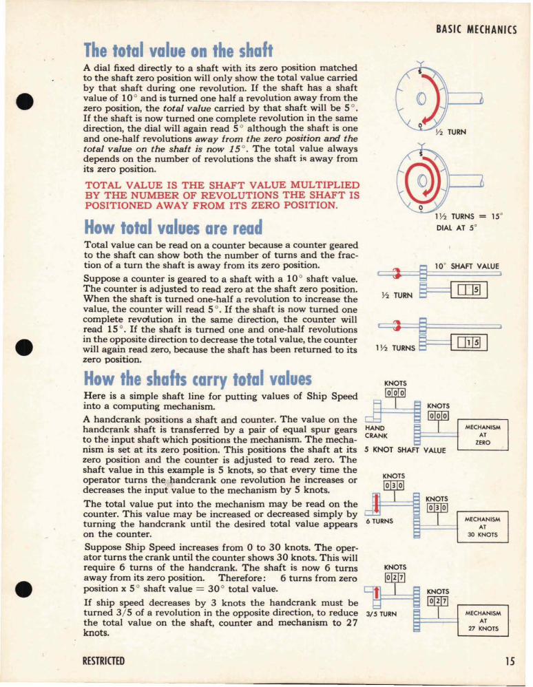
The total value on the shaft
1Y2 TURNS = 15°
DIAL AT 5°
A dial fixed directly to a shaft with its zero position matchedto the shaft zero position will only show the total value carriedby that shaft during one revolution. If the shaft has a shaftvalue of 10 0 and is turned one half a revolution away from thezero position, the total value carried by that shaft will be 50.If the shaft is now turned one complete revolution in the samedirection, the dial will again read 50 although the shaft is oneand one-half revolutions away from the zero position and the
. total value on the shaft is now 15 0• The total value always
depends on the number of revolutions the shaft is away fromits zero position.
TOTAL VALUE IS THE SHAFT VALUE MULTIPLIEDBY THE NUMBER OF REVOLUTIONS THE SHAFT ISPOSITIONED AWAY FROM ITS ZERO POSITION.
How total values are read
Y2 TURN
10° SHAFT VALUE
1Y2 TURNS
Total value can be read on a counter because a counter gearedto the shaft can show both the number of turns and the fraction of a turn the shaft is away from its zero position.
Suppose a counter is geared to a shaft with a 10 0 shaft value.The counter is adjusted to read zero at the shaft zero position.When the shaft is turned one-half a revolution to increase thevalue, the counter will read 50. If the shaft is now turned onecomplete revolution in the same direction, the counter willread 150. If the shaft is turned one and one-half revolutionsin the opposite direction to decrease the total value, the counterwill again read zero, because the shaft has been returned to itszero position.
5 KNOT SHAFT VALUE
KNOTS
@Iilll
MECHANISMAT
27 ·KNOTS
MECHANISMAT
ZERO
MECHANISMAT
30 KNOTS
KNOTS@0I]
3/5 TURN
How the shafts carry total valuesHere is a simple shaft line for putting values of Ship Speedinto a computing mechanism.
A handcrank positions a shaft and counter. The value on thehandcrank shaft is transferred by a pair of equal spur gearsto the input shaft which positions the mechanism. The mechanism is set at its zero position. This positions the shaft at itszero position and the counter is adjusted to read zero. Theshaft value in this example is 5 knots, so that every time theoperator turns the handcrank one revolution he increases ordecreases the input value to the mechanism by 5 knots.
The total value put into the mechanism may be read on thecounter. This value may be increased or decreased simply byturning the handcrank until the desired total value appearson the counter.
Suppose Ship Speed increases from 0 to 30 knots. The operator turns the crank until the counter shows 30 knots. This willrequire 6 turns of the handcrank. The shaft is now 6 turnsaway from its zero position. Therefore: 6 turns from zeroposition x 50 shaft value = 30 0 total value.
If ship speed decreases by 3 knots the handcrank must beturned 3/5 of a revolution in the opposite direction, to reducethe total value on the shaft, counter and mechanism to 27knots.
RESTRICTED 15
BASIC MECHANISMS OP 1140
Using CLAMPS 10 ADD and SUBTRACT a CONSTANTIn solving a fire control problem it is sometimes necessary toadd or subtract a constant from a value going into a mechanism. For example, some of the multipliers must be positionedby the values of the Time of Flight, minus a constant. In a caselike this, the crank input is Time of Flight, but the mechanismis positioned for Time of Flight minus K. The constant K canbe set into the transmission line by a sleeve coupling or aclamp gear.
CRANK SHAFT
SLEEVE COUPLING
SECONDS
5
INPUT SHAFT
MECHANISMPOSITIONEDAT 5 SEC.
Here is a sleeve coupling joining two shaftswhich must put Time of Flight in seconds,minus a constant 5 seconds, into the mechanism. Each shaft has a counter showing itsposition. Both shafts are positioned at 5 seconds.
SEC.
TIGHT LOOSE
MECHANISM
IJ---Ill;'] POSITIONEDAT ZERO
-5 OFFSET
Now if one clamp is loosened, the unit inputshaft can be turned till its counter reads zero,without moving the crank shaft. If this clampis now tightened, with the value of 5 secondson the crank shaft and zero on the input shaft,the two shafts will turn together when thecrank is turned. But the input to the mechanism will always be five seconds less thanthe crank input.
ZERO INPUT
16
MECHANISMPOSITIONEDAT 10 SEC.
MECHANISMPOSITIONEDAT 3 SEC.
MECHANISMPOSITIONEDAT 18 SEC.
If the crank is turned to the position for avalue of 15 seconds, the input to the mechanism will be 10 seconds, and so on.
This use of a clamp is called putting a constant offset on the line. The offset can be plusor minus.
Here's an example with a plus offset. Theclamp is tightened when the crank shaft is inzero position and the input shaft at 3. The input to the mechanism will always be 3 morethan the crank input value.
RESTRICTED
BASIC MECHANICS
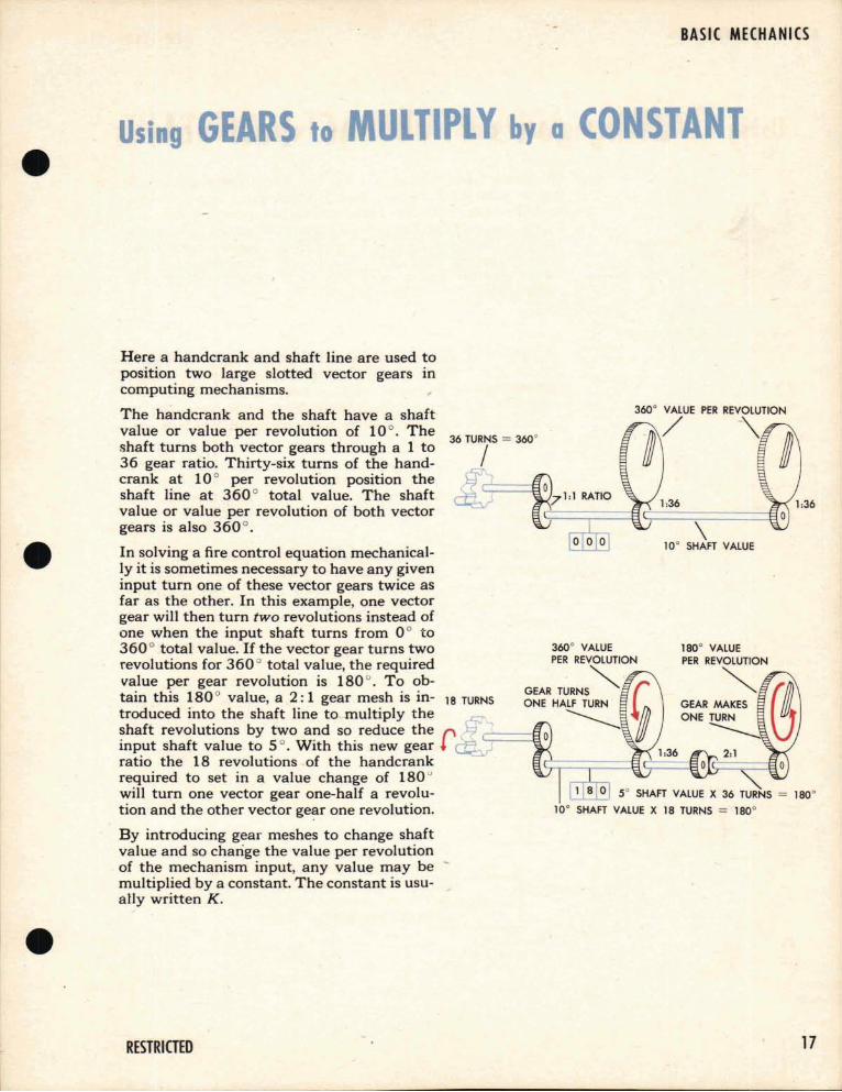
Using GEARS to MULTIPLY by a CONSTANT
\10° SHAFT VALUE
5° SHAFT VALUE X 36 TURNS == 180°
10° SHAFT VALUE X 18 TURNS == 180°
Here a handcrank and shaft line are used toposition two large slotted vector gears incomputing mechanisms.
The handcrank and the shaft have a shaftvalue or value per revolution of 10 0
• The 36 TURNS == 3600shaft turns both vector gears through a 1 to /36 gear ratio. Thirty-six turns of the handcrank at 10 0 per revolution position theshaft line at 360 0 total value. The shaftvalue or value per revolution of both vectorgears is also 360 0
•
In solving a fire control equation mechanically it is sometimes necessary to have any giveninput turn one of these vector gears twice asfar as the other. In this example, one vectorgear will then turn two revolutions instead ofone when the input sl).aft turns from 0 0 to360 0 total value. If the vector gear turns tworevolutions for 360 0 total value, the requiredvalue per gear revolution is 180 0
• To ob-tain this 180 0 value, a 2: 1 gear mesh is in- 18 TURNS
troduced into the shaft line to multiply theshaft revolutions by two and so reduce the f'input shaft value to 50. With this new gear ~ I
ratio the 18 revolutions of the handcrankrequired to set in a value change of 180 u
will turn one vector gear one-half a revolution and the other vector ge~r one revolution.
By introducing gear meshes to change shaftvalue and so change the value per revolutionof the mechanism input, any value may be -multiplied by a constant. The constant is usu-ally written K.
--
RESTRICTED 17
BASIC MECHANISMS OP 1140
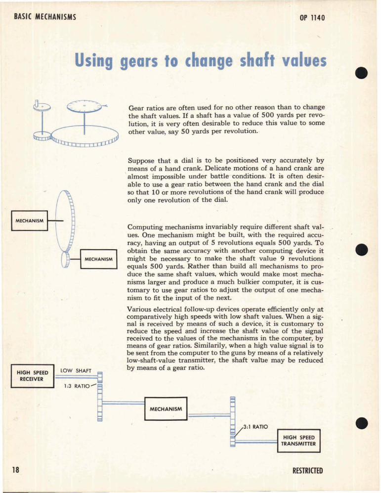
Using gears to change shaft values
Gear ratios are often used for no other reason than to changethe shaft values. If a shaft has a value of 500 yards per revolution, it is very often desirable to reduce this value to someother value, say SO yards per revolution.-
HIGH SPEEDRECEIVER
lOW SHAFT ~
1:3 RATIO"-
Suppose that a dial is to be positioned very accurately bymeans of a hand crank. Delicate motions of a hand crank arealmost impossible under battle- conditions. It is often desirable to use a gear· ratio between the hand crank and the dialso that 10 or more revolutions of the hand crank will produceonly one revolution of the dial.
Computing mechanisms invariably require different shaft values. One mechanism might be built, with the required accuracy, having an output of 5 revolutions equals 500 yards. Toobtain the same accuracy with another computing device itmight be necessary to make the shaft value 9 revolutionsequals 500 yards. Rather than build all mechanisms to produce the same shaft values, which would make most mechanisms larger and produce a much bulkier computer, it is customary to use gear ratios to adjust the output of one mechanism to fit the input of the next.
Various electrical follow-up devices operate efficiently only atcomparatively high speeds with low shaft values. When a signal is received by means of such a device, it is customary toreduce the speed and increase the shaft value of the signal!"eceived to the values of the mechanisms in the computer, bymeans of gear ratios. Similarily, when a high value signal is tobe sent from the computer to the guns by means of a relativelylow-shaft-value transmitter, the shaft value may be reducedby means of a gear ratio.
18
e:MECHANISM
~1/3:1 RATIO
~ HIGH SPEEDb TRANSMITTER
RESTRICTED
BASIC MECHANICS
Using gears to redu,ce lost ·motion errorsThe total amount of value loss due to lost motion in a shaftline de'pends on:
1 The size of the gears used
2 The shaft value carried by the shafts in one revolution
Larger gears reduce angular lost motion
30 TOOTH GEAR
ANGULAR LOST MOTION ----+------,L../IS 1/120 OF SHAFT REV,
rtT-----LOST MOTION AT TEETH = 1/4 OF TOOTH SPACE-7----/
\ t-_-'r-_ANGULAR LOST MOTIONIS 1/32 OF SHAFT REV,
SHAFT
8 TOOTH GEAR
Gear ratios are often used to reduce the effects of lost motion.The larger the gear, the less the lost motion in the gear meshaffects the accuracy of the shaft value. The lost motion wherethe teeth meet remains cons~ant but the angular lost motiondecreases as the gear diameter increases.
Because large driving gears have less angular lost motion intransmitting a signal mechanically from one mechanism inthe computer to another, it is often advantageous to reducethe shaft value with a gear ratio and step it up again at thepoint of delivery.
Howgear sizeand shaft valueaffect lost motion errorAssume that a shaft line has four 1 : 1 gear ratios and the valueper revolution of each shaft is 100 yards. If the gears used areall of such a size that the angular lost motion at each mesh isone yard, the greatest value error due to angular lost in theshaft line will be 4 yards.
If the gears used were twice as large, the linear lost motionbetween the meshing teeth would remain about the same; butthe angular lost motion would be half as great, thus cuttingthe value error in half, that is, to 2 yards.
If the shaft value per re olution were only 50 yards instead of100 yards, the maximu value error would also be cut in half.
It is important to understand that the maximum value errordue to angular lost motign remains the same regardless of thenumber of shaft revolutions. As soon as the teeth on all thegears in a shaft line take up the lost motion by moving to theirdriving position, the maximum value error is reached and cannot increase during any additional turning in the same direction.
! REV. ~ 100 YOS.
1 YARD LOSTAT EACHGEAR MESH
~MAXIMUM VALU,II'~RROR = 4 YARDS
RESTRICTED 19
BASIC MECHANISMS
CLOCKWISECOUNTERCLOCKWISE
GE TR I sOP 1140
DRMNG GEAR DRIVEN GEAR
IDLER
60 TEETH1/3 REV.
-rV',{VV"lt\,L
20 TEETH1 REV.
DRIVER
20 TEETH
DRIVER
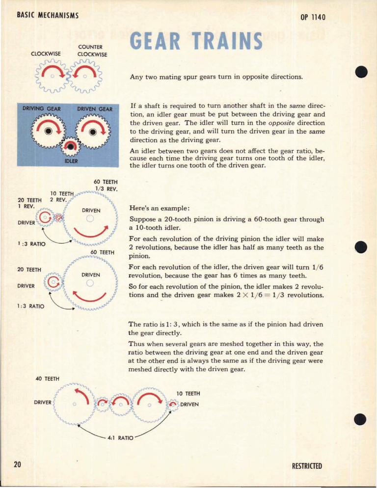
Any two mating spur gears turn in opposite directions.
If a shaft is required to turn another shaft in the same direction, an idler gear must be put between the driving gear andthe driven gear. The idler will turn in the opposite directionto the driving gear, and will turn the driven gear in the same
direction as the driving gear.
An idler between two gears does not affect the gear ratio, because each time the driving gear turns one tooth of the idler,the idler turns one tooth of the driven gear.
Here's an example:
Suppose a 20-tooth pinion is driving a 60-tooth gear througha 10-tooth idler.
For each revolution of the driving pinion the idler will make2 revolutions, because the idler has half as many teeth as thepinion.
For each revolution of the idler, the driven gear will turn 1/6revolution, because the gear has 6 times as many teeth.
So for each revolution of the pinion, the idler makes 2 revolutions and the driven gear makes 2 X 1/6 = 1/3 revolutions.
The ratio is 1: 3, which is the same as if the pinion had driventhe gear directly.
Thus when several gears are meshed together in this way, theratio between the driving gear at one end and the driven gearat the other end is always the same as if the driving gear weremeshed directly with the driven gear.
20 RESTRICTED
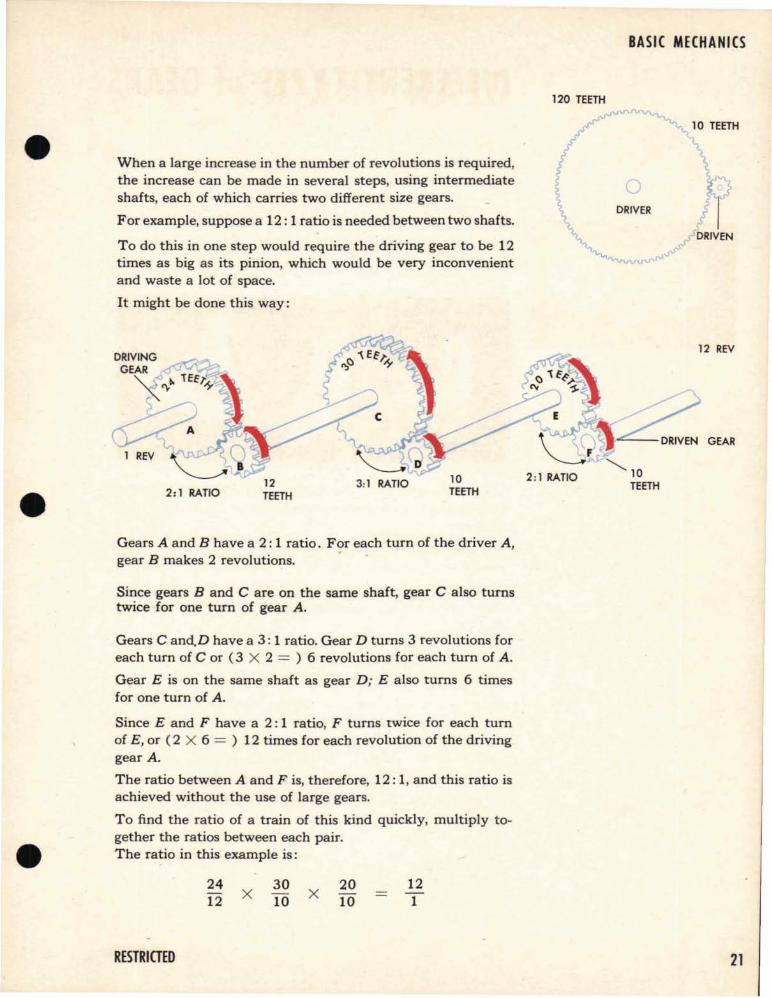
When a large increase in the number of revolutions is required,the increase can be made in several steps, using intermediateshafts, each of which carries two different size gears.
For example, suppose a 12: 1 ratio is needed between two shafts.
To do this in one step would require the driving gear to be 12times as big as its pinion, which would be very inconvenientand waste a lot of space.
It might be done this way:
BASIC MECHANICS
120 TEETH
10 TEETH
2:1 RATIO12TEETH
3:1 RATIO 10TEETH
12 REV
,<_r,o=.--DRIVEN GEAR
Gears A and B have a 2: 1 ratio. For each turn of the driver A,gear B makes 2 revolutions.
Since gears Band C are on the same shaft, gear C also turnstwice for one turn of gear A.
Gears C and.D have a 3: 1 ratio. Gear D turns 3 revolutions foreach turn of C or (3 X 2 = ) 6 revolutions for each turn of A.
Gear E is on the same shaft as gear D; E also turns 6 timesfor one turn of A.
Since E and F have a 2: 1 ratio, F turns twice for each turnof E, or (2 X 6 = ) 12 times for each revolution of the drivinggear A.
The ratio between A and F is, therefore, 12: 1, and this ratio isachieved without the use of large gears.
To find the ratio of a train of this kind quickly, multiply together the ratios between each pair.The ratio in this example is:
RESTRICTED
2412 X
3010 X
2010
121
21
BASIC MECHANISMS
MITER GEARS 1:1 RATIO
22
OP 1140
DIFFERENT TYPES of GEARSSo far only spur gears have been considered.
Spur gears will transmit motion only between parallel shafts.When shafts are not parallel bevel gears are usually used.
Bevel gears can transmit motion between shafts at almost anyangle to one another because bevel gears can be designed tosuit the angle between any two shafts.
By using bevel gears several shafts at different angles can bedriven by one driving shaft.
The gear ratios for bevels are found in the same way as forspur gears, by counting the teeth on each gear.
If a pair of bevel gears are of equal size and their shafts areat right angles, they are called MITER gears.
RESTRICTED
In SPIRAL GEARS, the teeth are cut slantwise across theface of the gear. One end of a tooth, therefore, lies ahead ofthe other. That is, each tooth has an "advanced end" and a"trailing end."
In straight tooth spur gears, the whole width of the face ofthe gear comes into contact at qne time. But in spiral gears,contact between two teeth starts first at.the advanced end ofeach tooth and moves progressively across the face of the gearuntil the trailing ends of the teeth are in contact.
Because of the slant cut of the teeth more than one tooth is ,inmesh at a time. This kind of meshing action keeps the gearssmoothly in contact with one another, resulting in smootherand quieter operation.
INTERNAL GEARS are gears with their teeth cut on theinside of a ring and pointing inward toward the axis of rotation.
An internal gear must mesh with an external gear, whose center is offset from the center of the internal gear.
Either the external or the internal gear can be the drivinggear. The gear ratio is the same as for external gears. It is:
The number of teeth in the driving gearThe number of teeth in the driven gear
Sometimes only a part of a gear is needed, where the motionof the pinion is limited.
In a case like this a sector gear is used to save space.
A sector gear is simply part of a gear.
RESTRICTED
BASIC MECHANICS
23
BASIC MECHANISMS OP 1140
STRAIGHT and ROTARY m tion
ROTARYMOTION
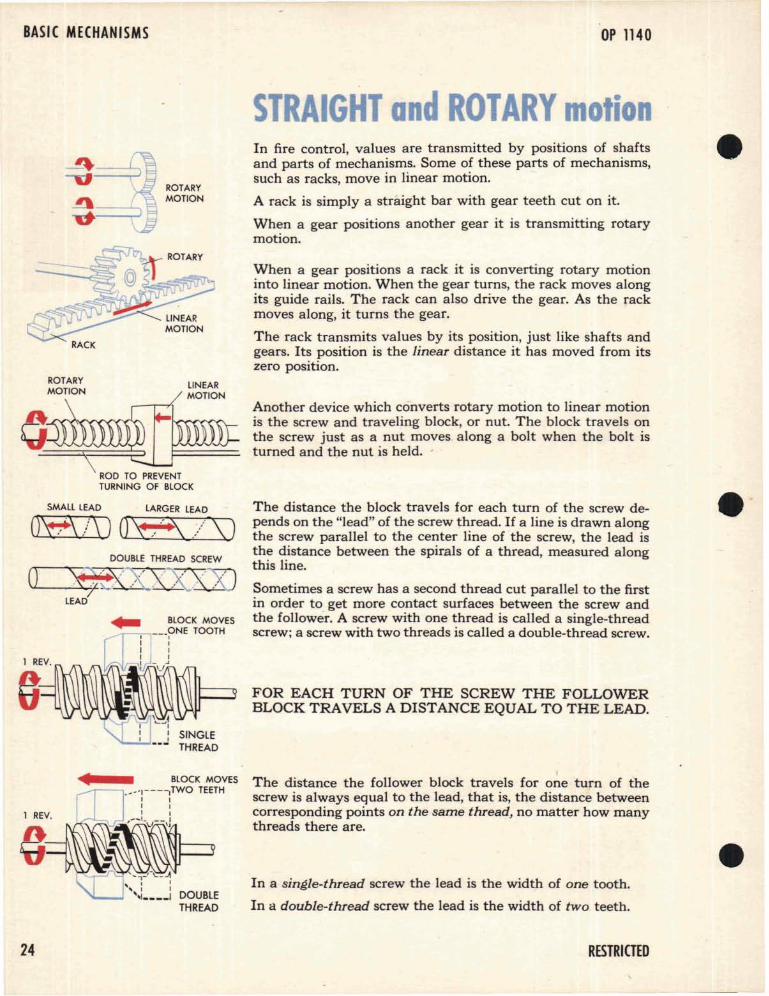
In fire control, values are transmitted by positions of shaftsand parts of mechanisms,. Some of these parts of mechanisms,such as racks, move in linear motion.
A rack is simply a straight bar with gear teeth cut on it.
When a gear positions another gear it is transmitting rotarymotion.
o~\ ROD TO PREVENT
TURNING OF BLOCK
SMALL LEAD LARGER LEAD
0'#\ is) O"E\ // \)
When a gear positions a rack it is converting rotary motioninto linear motion. When the gear turns, the rack moves alongits guide rails. The rack can also drive the gear. As the rackmoves along, it turns the gear.
The rack transmits values by its position, just like shafts andgears. Its position is the linear dista.nce it has moved from itszero position.
Another device which converts rotary motion to linear motionis the screw and traveling block, or nut. The block travels onthe screw just as a nut moves. along a bolt when the bolt isturned and the nut is held. -
The distance the block travels for each turn of the screw depends on the "lead" of the screw thread. If a line is drawn alongthe screw parallel to the center line of the screw, the lead isthe distance between the spirals of a thread, measured alongthis line.
Sometimes a screw has a second thread cut parallel to the firstin order to get more contact surfaces between the screw andthe follower. A screw with one thread is called a single-threadscrew; a screw with two threads is called a double-thread screw.
FOR EACH TURN OF THE SCREW THE FOLLOWERBLOCK TRAVELS A DISTANCE EQUAL TO THE LEAD.
SINGLETHREAD
()
1 REV.
1 REV.
• BLOCK MOVES~r---'._-T---,TWO TEETH
I II II I
, ....... L\./__,J
DOUBLETHREAD
The distance the follower block travels for one turn of thescrew is always equal to the lead, that is, the distance betweencorresponding points on the same thread, no matter how manythreads there are.
In a single-thread screw the lead is the width of one tooth.
In a double-thread screw the lead is the width of two teeth.
24 RESTRIGED
BASIC MECHANICS
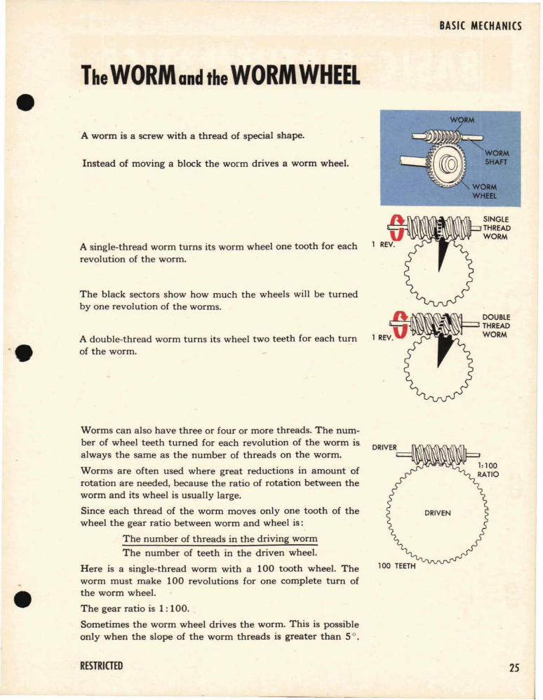
TheWORM and the WORM WHEELWORM
WORMSHAFT
SINGlETHREADWORM
A single-thread worm turns its worm wheel one tooth for eachrevolution of the worm.
A worm is a screw with a thread of special shape.
Instead of moving a block the worm drives a worm wheel.
The black sectors show how much the wheels will be turnedby one revolution of the worms.
1j~~~~~=::JDOUBLE'} THREAD
A double-thread worm turns its wheel two teeth for each turn 1 REV. WORM
of the worm.
Worms can also have three or four or more threads. The number of wheel teeth turned for each revolution of the worm is.always the same as the number of threads on the worm.
Worms are often used where great reductions in amount ofrotation are needed, because the ratio of rotation between theworm and its wheel is usually large.
Since each thread of the worm moves only one tooth of thewheel the gear ratio between worm and wheel is:
The number of threads in the driving worm
The number of teeth in the driven wheel.
Here is a single-thread worm with a 100 tooth wheel. Theworm must make 100 revolutions for one complete turn ofthe worm wheel.
The gear ratio is 1: 100.
Sometimes the worm wheel drives the worm. This is possibleonly when the slope of the worm threads is greater than So.
RESTRICTED 25
BASIC MECHANISMS OP 1140
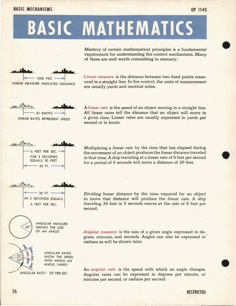
BASIC MATHEMATICSMastery of certain mathematical principles is a fundamentalrequirement for understanding fire control mechanisms. Manyof these are well worth committing to memory:
1000 YDS
LINEAR MEASURE INDICATES DISTANCE
~~40 KNOTS
LINEAR RATES REPRESENT SPEED
6 FEET PER SEC.
FOR 5 SECONDSEQUALS 30 FEET
1+-- 30 FT. --+I
~-- 30 FT. --+l
IN 5 SECONDS EQUALS
6 FEET PER SEC.
Linear measure is the distance between two fixed points measured in a straight line. In fire control, the units of measurementare usually yards and nautical miles.
A linear rate is the speed of an object moving in a straight line.All linear rates tell the distance that an object will move ina given time. Linear rates are usually expressed in yards persecond or in knots.
Multiplying a linear rate by the time that has elapsed duringthe movement of an object produces the linear distance traveledin that time. A ship traveling at a linear rate of 6 feet per secondfor a period of 5 seconds will move a distance of 30 feet.
Dividing linear distance by the time required for an objectto move that distance will produce the linear rate. A shiptraveling 30 feet in 5 seconds moves at the rate of 6 feet persecond.
ANGULAR MEASURESHOWS THE SIZEOF AN ANGLE
ANGULAR RATESSHOW THE SPEEDWITH WHICH ANANGLE VARIES
Angular measure is the size of a given angle expressed in degrees, minutes, and seconds. Angles can also be expressed in·radians as will be shown later.
An angular rate is the speed with which an angle changes.Angular rates can be expressed in degrees per minute, orminutes per second, or radians per second.
26 RESTRICTED
A quantity that changes is called a variable. For example, theRANGE input to a computer is a variable because the rangevalue is constantly changing as the position of the Targetchanges with relation to Own Ship.
A variable that derives its value from another variable is called• a function of that variable. When the function increases or de
creases uniformly as the variable increases, the function iscalled a linear function. If an object is moving at a constantvelocity, the distance it travels is a linear function of the timeof travel. Distance equals velocity times time.
In fire control problems, an empirical function is one whosevalue in relation to a variable has been established by observation. Ballistic cams deliver empirical functions because thedata cut into each cam is based on the observations of theflight of the projectile.
A constant is a quantity whose value does not change.
A variable is often multiplied by a constant to produce an approximation of another variable. When a constant is added toor subtracted trom a variable, it is called an offset.
BASIC MATHEMATICS
RANGE IS A VARIABLEBECAUSE IT CHANGES
BALLISTIC CAMS PRODUCEEMPIRICAL FUNCTIONS
DRIVER"
-DRIVEN
GEAR RATIOS PROVIDE A CONSTANTFOR MULTIPLICATION
OFFSET
AN OFFSET IS A CONSTANT TO BEADDED OR SUBTRACTED
The reciprocal of a number is 1 divided by that number. Thereciprocal of 5 is 1/5. Multiplying by the reciprocal of a number is the same as dividing by that number. Division in mechanical computers i~ usually accomplished through multiplication by the reciprocal.
RESTRICTED
RECIPROCALS CANBE COMPUTED BYA CAM
27
BASIC MECHANISMS,
OP 1140
ight TrianglesANGLE A +ANGLE B+ANGlE C = 180°
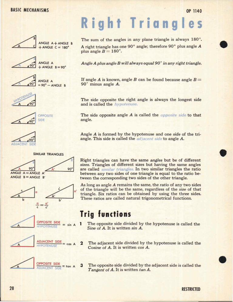
The sum of the angles in any plane triangle is always 180 0.
A right triangle has one 90° angle; therefore 90° plus angle Aplus angle B = 180°.
~ANGlEA~ +ANGlE B=90°
Angle A plus angle B will always equal 90° in any right triangle.
A . ANGLE A
AW =90° - ANGLE B
If angle A is known, angle B can be found because angle B =90 ° minus angle A.
The side opposite the right angle is always the longest sideand is called the hypotenuse.
OPPOSITESIDE
The side opposite angle A is called the opposite side to thatangle.
Angle A is formed by the hypote"nuse and one side of the triangle. This side is called the adjacent side to angle A.
= sin A 1 The opposite side divided by the hypotenuse is called theSine of A. It is written sin A.
Right triangles can have the same angles but be of differentsizes. Triangles of different sizes but having the same anglesare called sImIlar trzangles. In two similar triangles the ratiobetween any two sides of one triangle is equal to the ratio between the corresponding two sides of the other triangle.
As long as angle A remains the same, the ratio of any two sidesof the triangle will be the same, regardless of the size of thattriangle. Six ratios can be obtained by using the three sides.These ratios are called natural trigonometrical functions.
Trig functions
SIMilAR TRIANGLES
~~ANGLE A =ANGLE A'ANGLE B=ANGLE B'
OPPOSITE SIDE="-:"':__-' H POTENUSE
ADJACENT SIDEHYPOTENUSE = cos A 2 The adjacent side divided by the hypotenuse is called the
Cosine of A. It is written cos A.
OPPOSITE SIDE.:;.,.Q__...... ADJACENT SIDE =tan A 3 The opposite side divided by the adjacent side is called the
Tangent of A. It is written tan A.
28 RESTRICTED
BASIC MATHEMATICS
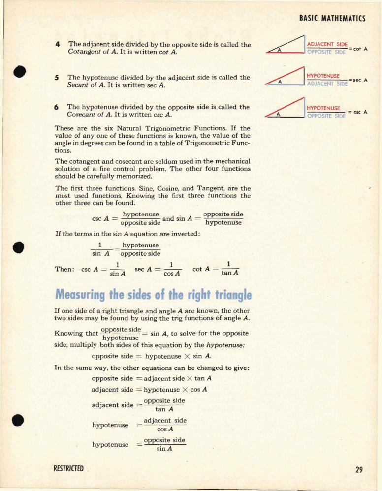
4 The adjacent side divided by the opposite side is called theCotangent of A. It is written cot A.
ADJACENT SIDE...............__-11 OPPOSITE SIDE = cot A
5 The hypotenuse divided by the adjacent side is called theSecant of A. It is written sec A.
HYPOTENUSE
"::::;,,,,,:,;;:,-,,,_-, ADJACENT SIDEsec A
6 The hypotenuse divided by the opposite side is called theCosecant of A. It is written csc A. ~IHYPOTENUSE
-=-==-=-==--=- =esc AA OPPOSITE S DE
These are the six Natural Trigonometric Functions. If thevalue of anyone of these functions is known, the value of theangle in degrees can be found in a table of Trigonometric Functions.
1cot A = tan AThen:
The cotangent and cosecant are seldom used in the mechanicalsolution of a fire control problem. The other four functionsshould be carefully memorized.
The first three functions, Sine, Cosine, and Tangent, are themost used functions. Knowing the first three functions theother three can be found.
Ahypotenuse d' A opposite side
csc = .. an SIn =OpposIte sIde hypotenuse
If the terms in the sin A equation are inverted:
1 _ hypotenusesin A opposite side
1 1csc A = ----:--A sec A = -ASIO cos
Measuring the sides of the right triangle
hypotenuse
If one side of a right triangle and angle A are known, the othertwo sides may be found by using the trig functions of angle A.
K . h opposite side. I f h .nowlOg t at = SIO A, to so ve or t e OpposItehypotenuse .
side, multiply both sides of this equation by the hypotenuse:
opposite side .~ hypotenuse X sin A.
In the same way, the other equations can be changed to give:
opposite side = adjacent side X tan A
adjacent side = hypotenuse X cos A
d" 'd opposite side
a Jacent SI e = t A. an
adjacent sidecosA
hypotenuseopposite side
sin A
RESTRICTED . 29
BASIC MECHANISMS
\
OP 1140
VECT 0 RSA vector, as used in a fire control problem, is a straight line witha definite length and direction which may represent either alinear rate or a linear distance.
c7'
~A VECTORc:::/' REPRESENTS AN
ACTUAL SPEEDOR DISTANCEIN A GIVENDIRECTION
ayb
y
x ------n::-Jli===-..
IHORIZONTALCOMPONENTS
VIIZW
-'z<0~Q..I-;:E~O>u
To add or subtract vectors with different directions, it is necessary to break them up into components, with reference to acommon axis, and add or subtract the corresponding com-ponents. ...
Suppose that two vectors with different directions are drawnfrom a common point. Their components from the point in ahorizontal and vertical direction can be found by solving thetwo right triangles formed.
The y components are d sin A and c cos BThe x components are d cos A and c sin B
Solving an equationAn algebraic equatIon may be solved or simplified by addingthe same value or subtracting the same value from both sidesof the equation, or by multiplying or dividing both sides of theequation by the same value.
In the equation ay = bx, x can be found by dividing both sidesof the equation by b.
ay bx-- = -- or'x
b b '
In the same equation, y may be found by dividing the originalequation by a.
aya
bxa
or, y =bxa
30
If the equation read y = bX, the value of x could be found bya
multiplying both sides of the equation by : .
ay abx ayb = ----aJ) or, x = b
The values of a or b may be derived in the same manner.
RESTRICTED
RADIANSThe usual way to measure an angle is in degrees and minutes.The circumference of a circle is divided into 360 equal parts,or degrees. Each degree is further divided into 60 minutes.
Another extremely 'useful system of measuring angles is calledradian measure.
In radian measure, an arc equal in length to a radius of a circleis measured on the circumference of that circle. When two radiiare drawn to the ends of this arc, the angle they measure iscalled a radian. A circle contains 6.28 radians.
A circle contains 6.28 radians because the circumference ofany circle equals 27T times the radius. As 7T equals 3.14 (approx.) then 27T equals 6.28. Since one radius measures oneradian on the circumference there are always 27T or 6.28 radians in a circle.
Angles expressed in radians can be translated to angles expressed in degrees if it is remembered that 27T radians equal360°.
360 0
One radian = 6.28 or 57 0 18'
The chief importance of the radian measure in fire control isthat the radian can be used to translate two linear measurements, such as target movement and range, into an angularmeasurement. If the target movement in a given period of timeis known, and the range is known, the angular movement ofthe target can be expressed as a fraction of the range. Considering the range to be a radius, the fraction obtained will be theangular target movement in radians.
It should be borne in mind, however, that the radian is a curvedunit, whereas the linear movement of a target is in a straightline. For the purposes of computation it is within the limitsof accuracy to assume that the straight line and the curved arcof the radian are equal in length when the straight line measures a small angle.
RESTRIGED
BASIC MATHEMATICS
.28RADIAN
~~
r"IIII"'_11'l"~~<:)
~4D'A~
ONE RADIAN _57°18'
./L1NEAR~ TARGET
MOVEMENT
31
BASIC MECHANISMS OP 1140
OUTPUT
INPUT
INPUT
COUNTER
C¥JCOUNTER
DfJ
/SETTINGCLANP
32
BASICMECHANISM 1---....
COUNTER
BASICMECHANISM
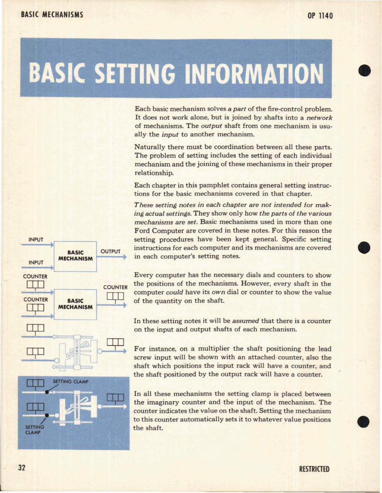
Each basic mechanism solves a part of fhe fire-control problem.It does not work alone, but is joined by shafts into a networkof mechanisms. The output shaft from one mechanism is usually the input to another mechanism.
Naturally there must be coordination between all these parts.The problem of setting includes the setting of each individualmechanism and the joining of these mechanisms in their properrelationship.
Each chapter in this pamphlet contains general setting instructions for the basic mechanisms covered in that chapter.
These setting notes in each chapter are not intended for making actual settings. They show only how the parts of the variousmechanisms are set. Basic mechanisms used in more than oneFord Computer are covered in these notes. For this reason thesetting procedures have been kept general. Specific settinginstructions for each computer and its mechanisms are coveredin each computer's setting notes.
Every computer has the necessary dials and counters to showthe positions of the mechanisms. However, every shaft in thecomputer could have its own dial or counter to show the valueof the quantity on the shaft.
In these setting notes it will be assumed that there is a counteron the input and output shafts of each mechanism.
For instance, on a multiplier the shaft positioning the leadscrew input will be shown with an attached counter, also theshaft which positions the input rack will have a counter, andthe shaft positioned by the output rack will have a counter.
In all these mechanisms the setting clamp is placed betweenthe imaginary counter and the input of the mechanism. Thecounter indicates the value on the shaft. Setting the mechanismto this counter automatically sets it to whatever value positionsthe shaft.
RESTRICTED
Here are a few things to remember in reading these settinginstructions:
1 All setting clamps are loose before adjustment. They aretightened when the setting is completed.
2 Many mechanisms are set by positioning one input at zero,-_and then moving the other input while watching the outputfor zero or minimum motion. Take a multiplier for example: Any number multiplied by zero equals zero, so ifone input to the multiplier is put at its zero position, movement of the other input should produce no movement ofthe output.
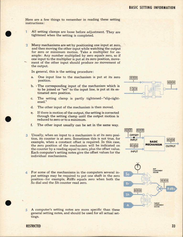
In general, this is the setting procedure:
a. One input line to the mechanism is put at its zeroposition.
b. The corresponding input of the mechanism which isto be joined or "set" to the input line, is put at its estimated zero position.
c. The setting clamp is partly tightened-"slip-tightened."
d. The other input of the mechanism is then moved.
e. If there is motion of the output, the- setting is correctedthrough the setting clamp until the output motion isreduced to zero or to a minimum.
BASIC SETTING INFORMATION
f. The other input usually can be set in the same way.
3 Usually, when an input to a mechanism is at its zero position, its counter is at zero. Sometimes this is not true, forexample, when a constant offset is required. In this case,the zero position of the mechanism will be indicated onthe counter by a reading equal to zero, plus the offset value.Each computer's setting notes give the offset values for theindividual mechanisms.
4 For some of the mechanisms in the computers several input settings may be required to put one shaft in the zeroposition-for example, RdBs equals zero when both theSo dial and the Sh counter read zero.
S A computer's setting notes are more specific than thesegeneral setting notes, and should be used for all actual settings.
RESTRICTED
~;r[OFFSET r-----...,-~~
INPUT BASIC
~ ....... MECHANISM
INPUT
SHIP .COMPONENTSOLVER
TARGETCOMPONENTSOLVER
~OUTPUT
33
BASIC MECHANISMS OP 1140
Here and there in the setting notes are instructions like"Observe the motion of the indicator," "Push the cam," or"Wedge the input." It will be- a good idea to find out how todo these things now.
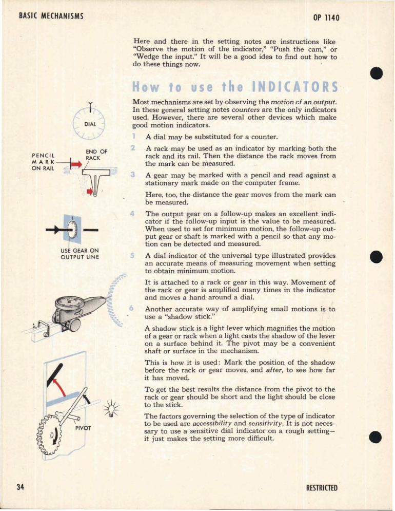
Most mechanisms are set by observing the motion cf an output.In these general setting notes counters are the only indicatorsused. However, there are several other devices which makegood motion indicators.
A dial may be substituted for a counter.
2 A rack may be used as an indicator by marking both therack and its rail. Then the distance the rack moves fromthe mark can be measured.
A gear may be marked with a pencil and read against astationary mark made on the computer frame.
Here, too, the distance the gear moves from the mark canbe measured.
The output gear on a follow-up makes an excellent indicator if the follow-up input is the value to be measured.
.When used to set for minimum motion, the follow-up output gear or shaft is marked with a pencil so that any motion can be detected and measured.
A dial indicator of the universal type illustrated providesan accurate means of measuring movem~nt when settingto obtain minimum motion. -
It is attached to a rack or gear in this way. Movement ofthe rack or gear is amplified many times in the indicatorand moves a hand around a dial.
Another accurate way -of amplifying small motions is touse a "shadow stick."
A shadow stick is a light lever which magnifies the motionof a gear or rack when a light casts the shadow of the leveron a surface behind it. The pivot may be a convenientshaft or surface in the mechanism.
This is how it is use.si: Mark the position of the shadowbefore the rack or gear moves, and after, to see how farit has moved.
To get the best results the distance from the pivot to therack or gear should be short and the light should be closeto the stick.
The factors governing the selection of the type of indicatorto be used are accessibility and sensitivity. It is not necessary to use a sensitive dial indicator on a rough settingit just makes the setting more difficult.
6
\PIVOT
yI
DIAL
I
-+-f)-I
USE GEAR ONOUTPUT LINE
END OF
~E~~I~----l...~
ON RAIL I" .
34 RESTRICTED
BASIC SETTING INFORMATION
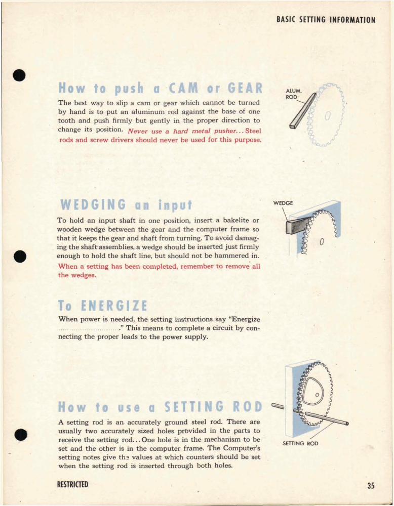
The best way to slip a cam or gf;!ar which cannot be turnedby hand is to put an aluminum rod against the base of onetooth and push firmly but gently in the proper direction to
change its position. Never use a hard metal pusher... Steelrods and screw drivers should never be used for this purpose.
To hold an input shaft in one positIOn, insert a bakelite orwooden wedge between the gear and the computer frame sothat it keeps the gear and shaft from turning. To avoid damag-
. ing the shaft-assemblies, a wedge should be inserted just firmlyenough to hold the shaft line, but should not be hammered in.
,When a setting has been completed, remember to remove allthe wedges.
WEDGE
When power is needed, the setting instructions say "Energize......" This means to complete a circuit by con
necting the proper leads to the power supply.
A setting rod is an. accurately ground steel rod. There areusually two accurately sized holes prc>Vided in the parts toreceive the setting rod... One hole is in the mechanism to beset and the other is in the computer frame. The Computer'ssetting notes give th~ values at which counters should be setwhen the setting rod is inserted through both holes.
SETIING ROD•RESTRICTED 35
BASIC MECHANISMS OP 1140
SETIING CLAMP
___1 0_'0_'-11
i ~
Clamps are mechanical "knots." They are used to tie inputsand mechanisms together, and to join the mechanisms of acomputer into a network. Because clamps are adjustable, theycan join these mechanisms in their proper relationship.
Setting clamps are placed in a computer so that they controlthe inputs to a mechanism or a series of mechanisms. Whereever possible, they are placed where they are easy to reach andeasy to see. Any clamp in a computer, whether a setting clampor an assembly clamp, can be used for setting. If any clamp becomes loose, it disturbs the network.
Here is a simple setting.
The clamp controls the relationship between the right and leftsides. The counters indicate the value on each side of the clamp.
Most of the time the values have to be made equal. Here thisis shown by a similar readin~ on both the counters.
When the counters are in agreement and the clamp has beentightened, the setting is complete.
PSCL
RIGHT SIDELEFT SIDE
1~ ~_.I~____..... TURN
Here the two sides of the clamp disagree.... Tightening theclamp now would make the right side in error by the amountof S.
The error can be corrected by holding the left side and movingthe right until the counter readings match.
Now tightening the clamp completes the setting.
_~....~I~__~_. ~__L.l....~_i0_'
Sometimes the sides should not be equal. A constant offs~t, K,can be added or subtracted by a clamp. Tightening the clampwhen one side differs from the other by the constant K completes the setting. Here the constant is 20.
"Slipping through the clamp," means changing the relationshipbetween two mechanisms controlled by the clamp, by holdingone and turning the other.
"Slip-tighten the clamp," means to make the clamp tightenough to drive, but loose enough to allow "slipping throughthe clamp."