100
January 2 0 1 9 BUREAU OF WATER & SEWER OPERATIONS NEW YORK CITY CROSS-CONNECTION CONTROL PROGRAM HANDBOOK Prepared By: NYC-DEP 2019 Version
January
2 0 1 9
BUREAU OF WATER & SEWER OPERATIONS
NEW YORK CITY
CROSS-CONNECTION CONTROL PROGRAM
HANDBOOK
Prepared By:
NYC-DEP
2019 Version

D I S C L A I M E R
As DEP has prepared this Handbook in good faith, practicing all due care and diligence,
neither DEP nor any individual give any representation or warranty, expressed or
implied, as to the relevance, completeness or fitness of this document in respect of any
particular user’s circumstances. All users of this Handbook should satisfy themselves
concerning its application to their situation and, if necessary, consult professional advice.
A B S T R A C T
DEP has compiled this information, to provide immense guidance, in an effort to aid all
professionals and customers involved in the design and installation of containment BFP
assemblies in the areas of the City of New York (NYC). This information is broken down into
identifiable sections so as to be easily referenced. For fundamental knowledge and a thorough
understanding of CCC/BFP requirements and design criteria for CCC plans, ordinances and
polices; this entire Handbook serves as an informative reference and should be carefully studied.
It presents the basics of backflow theory and helps filing the BFP plans correctly to expedite the
approval process and keep the project on schedule. However, this does not impose any
responsibility on the DEP for regulating plumbing.
Safe, Abundant Drinking Water
New York City – Department of Environmental Protection Cross-Connection Control (Backflow Prevention) Program
NYC - Cross-Connection Control Program Handbook
FOR CONTAINMENT PURPOSES ONLY
Please consider the environment before printing this manual
NYC- Cross-Connection Control Program Handbook, January 2019
3 3 3
Page Subject
4 Section 1 4
5
6 7
8
9 10
12 Section 2
12 13
13
13 14
14
15
15
15
19 20
21
22 23
25
27 27
28 28
30
32 34
35
36 37
38
40 40
40
41 46
47
49 Section 3 51 Section 4
52
54 56
57
57 58
59
60 61
62
63 Section 5 64
65
66 67
68
69 Section 6 74 Section 7
75 Section 8
88 Section 9 90 Appendix 1
91 Appendix 2
98 Appendix 3
PREVIEW
1. SCOPE 2. POLICY
3. WHO IS AFFECTED?
4. WHAT IS A CROSS-CONNECTION? 5. BFP ASSEMBLY APPROVAL PROCESS
6. SEQUENTIAL APPROVAL PROCESS of BFP PLANS
7. HOW TO COMPLY? STANDARDS
1. Degree of Hazard
2. Roles and Responsibilities for Cross-Connection Control A. Local Authority
B. Property owner/customer’s liability
C. Result of Non-Compliance (Enforcement Unit) D. NYC Licensed Master Plumber’s liability
E. Licensed Professional Engineer/Registered Architect (Applicant) liability
3. Cross-Connection Control Regulations A. Requirements and Considerations
B. Water System
C. Types of Water Services D. On-Site Auxiliary (Untreated) Water Source
E. Characteristics of the BFP Assemblies
F. Location/Installation/Requisites of BFP Assemblies G. Approved BFP Assemblies
H. Orientation of BFP Assemblies
I. Metering and Strainer J. Control Valves
K. Water-Based Fire Protection System (FPS)
L. Drainage Provisions M. Status of BFP Assemblies
N. Actions and Procedures
4. DEP Policies A. Types of Water Service Connections
B. Types of BFP Assemblies Installations
C. BFP Assemblies Installation Criteria
D. Plan Review Process
1. Application Form NYC GEN236
2. Plot Plan (Site Plan) 3. Elevation View (Riser Plan)
4. Plan View (Floor Plan) 5. Time Calculation before RPZA/RPDA Floods
Typical Significant Risk of Cross-Connection Hazards
PROGRAM FORMS, LETTERS AND RISK ASSESSMENT CHARTS - Form GEN236 (Application for Approval of BFP Assemblies)
- Form GEN215B (Report on Test and Maintenance of Containment BFP Assembly)
- Review Form for BFP Plan 1. Assessment of Fire Protection Water System (SP/SD)
2. Assessment of Domestic Water System
3. Methods of Backflow Protection for premises containment/isolation 4. Cross-Connection Control Risk Assessment Charts:
A. General Fire Sprinkler/Standpipe System
B. General Domestic Water System C. Process of Hazard Assessment
1. Instructions for Getting a Backflow Prevention Exemption
2. DEP Regulations for Residential Dwellings 3. Risk Assessment of Residential Dwellings
- Exemption Letter
- Example (annex to DEP Regulations for premises isolation) - Example for multiple water service lines, either separate or parallel/Annotation
SAMPLE ENGINEERING REPORT
NOMENCLATURE (LEGEND) EXAMPLES
Things to keep in mind: Summing-up Notes (Putting All Together)
Modifications to any USC Approved Backflow Prevention Assemblies GLOSSARY
Bibliography (works cited)
TABLE OF CONTENTS CCC Program Handbook 2019

NYC- Cross-Connection Control Program Handbook, January 2019
4
Section 1 PREVIEW
1. S C O P E
The Cross-Connection Control Program Handbook is developed and optimized by the New York City
Department of Environmental Protection (DEP) as general reference guidance of Standard Specifications
and Procedures for Prevention of Water Contamination and made available as a courtesy to the Public.
This Handbook is compiled in 9 Sections and 3 Appendices as a reference document and training manual
to promulgate the Code (Federal, State and City rules and regulations) and is not a how-to book.
To maintain consistency of the Cross-Connection Control (CCC) system, these guidelines have been
clarified in this text. Links were valid as of date of publication of this Handbook.
The purpose of this Handbook is to provide background for the proper use of Backflow Prevention (BFP)
Assemblies and explain the steps required to receive approval for the installation of BFP assemblies.
These guidelines clearly outline what an acceptable design and installation constitutes based on
experience in implementing CCC programs and policies set forth by United States Environmental
Protection Agency (USEPA), Occupational Safety and Health Administration (OSHA), University of
Southern California for Cross-Connection Control and Hydraulic Research (USC-FCCCHR), American
Water Works Association (AWWA) and New York State (NYS) and Local Health Departments (DOH).
The term “shall” indicates a requirement, the term “should” indicates a recommendation for good
waterworks practice and the term “may” is permissive.
None of the examples are intended to promote any specific manufacturer, product, device or assembly.
The mention of trade names and commercial products in this Handbook are for illustrative purposes only
and does not constitute an endorsement or recommendation.
This Handbook may be amended at any time at the discretion and approval of DEP. Hence, this
Handbook supersedes any previous editions. In the event this Program Handbook is found to conflict with
Federal and State law, currently or in the future, the Federal or State law will take precedence.

NYC- Cross-Connection Control Program Handbook, January 2019
5
2. “P O L I C Y”
BACKFLOW REGULATIONS
Purpose To protect the public potable water supply served by NYC-DEP Water Authority from contamination or
pollution which could backflow from customers’ internal water distribution system, by containment.
To promote the elimination or control of cross-connections, actual or potential, temporary or permanent.
To properly assess the water system to install an appropriate type of BFP assembly for the properties’ level of
health hazard, i.e. level of actual or potential risk to the public health. This will systematically and effectively
prevent the contamination or pollution of the public water supply (CWM).
AUTHORITY Federal Regulations: In 1974, the United States Congress passed the Safe Drinking Water Act (SDWA) to help ensure that tap water is
safe to drink. Under the provisions of the SDWA, the water purveyor is held primarily responsible to ensure water
quality meets national standards of safe drinking water established through the USEPA. These provisions include a
warranty that the water quality provided by the purveyor is in conformance with USEPA standards at the source, and
that the water is delivered to the customer without compromising its quality. Also, OSHA requires that no cross-
connection be allowed in an installation unless it is properly protected with an approved backflow preventer.
NYS–DOH
The water supply is to be adequate, safe, and of sanitary quality from an acceptable source that meets the
requirements of Part 5 of this Title (14-1.120 Water supply).
DEP POLICY
To protect public health and the environment by supplying clean drinking water, collecting and treating wastewater;
and reducing hazardous substances pollution.
DEP MISSION
Water is one of our basic necessities for survival. Living in an environment with a good source of clean potable
water is always a top priority as it is highly related to the public health.
We aspire to provide the safest potable water to protect human health and ensure hygienic environment.

NYC- Cross-Connection Control Program Handbook, January 2019
6
3. GENERAL OVERVIEW OF THE NYC
DEPARTMENT OF ENVIRONMENTAL PROTECTION
CROSS-CONNECTION CONTROL PROGRAM For the Protection of the Water Supply System
from Contamination
WHO IS AFFECTED?
Owners of properties that pose an actual or potential risk of contamination to NYC’s water
supply. This includes property with any of, but not limited to, the following facilities or
appurtenances:
AUTO BODY / REPAIR SHOPS HEAT EXCHANGERS
BABTISMAL POOL, MIKVAH; (ABLUTION), PONDS
AND FOUNTAINS
HOTELS AND/OR MOTELS
BAKERY IN-GROUND IRRIGATION SPRINKLER
BEAUTY SALONS OR BARBER SHOPS LARGE BOILERS (MORE THAN 350,000 BTU)
BIDETS MEDICAL OFFICES/ LABORATORIES/ DIALYSIS
(INCLUDES PSYCHOLOGY & PSYCHIATRIC
OFFICES THAT ADMINISTER MEDICATION)
BOOSTER/FILL PUMPS METAL MANUFACTURING, CLEANING,
PROCESSING OR FABRICATING PLANTS
BUTCHERS (INCLUDES FISH MARKETS & LIVE
STOCK
MULTIPLE DOMESTIC WATER SERVICES
CAR WASH PHARMACY
CHEMICALS USED IN PROCESSING e.g.
DYE PLANTS, PHOTO LABORATORIES
PRESSURE TANKS
CHEMICALLY TREATED BOILERS PRIVATE WELLS
COMMERCIAL LAUNDRY FACILITIES WITH COIN-
OPERATED MACHINES
SEWEGE TREATMENT OR HANDLING
DELICATESSEN / COMMERCIAL KITCHENS /
RESTAURANTS / PREMISES WHERE FOOD IS
BEING PREPARED, PROCESSED OR SERVED,
CANNED AND CONCENTRATED
SWIMMING POOLS / COMMERCIAL SWIMMING
POOLS
DENTAL OFFICES AND LABORATORIES VETERINARY OFFICES / LABORATORIES
DISTILLED BREWERIES WAREHOUSES (WITH TOXIC CHEMICALS
STORAGE)
DRY-CLEANING ESTABLISHMENTS WATER COOLED EQUIPMENT OR CHILLERS
FUNERAL PARLORS WATER REUSE / RECLAIMED / RECYCLING
GAS STATIONS AND/OR MINI MARTS WITH SODA
MACHINS OR COFFEE LINES
WATER STORAGE TANKS
GREEN HOUSES WELLS (GROUNDWATER)
Refer to: Typical Significant Risk of Cross-Connection Hazards, P. 49

NYC- Cross-Connection Control Program Handbook, January 2019
7
4. WHAT IS A CROSS-CONNECTION?
A cross-connection is any actual or potential physical connection between a potable water line and any
pipe, vessel, or machine containing a non-potable fluid, or has the possibility of containing a non-potable
fluid, solid or gas, such that it is possible for the non-potable fluid, solid or gas to enter the potable water
system by backflow.
Concept of Backflow
The term “Cross-Connection Control” is referring to backflow prevention. A cross-connection is an
arrangement of piping which could allow undesirable water or contaminants to enter the potable water
system as a result of backflow due to a backpressure or backsiphonage situation. All cross-connections
are prohibited except where BFP assemblies as specified by DEP are set. Cross-connections shall be
protected to prevent backflow, which can be hard to detect. In any water distribution system, potential
cross-connections and sources of contamination and pathogen intrusion can be varied and unpredictable.
Backflow means any reversal in the flow of water from its intended direction of flow either by
“backsiphonage” or by “backpressure”. When conditions are such that the water ceases to flow toward
the customers’ various fixtures and outlets and begins to flow from the intended outlets toward the source
of supply, the water supply can easily become contaminated through unprotected cross-connections.
Backsiphonage is caused by a reduced or negative pressure being created in the supply piping. Major
causes of backsiphonage are undersized piping and the interruption of the supply pressure. This will allow
negative pressures to be created by water trying to flow to a lower point in the system causing a foreign
substance to flow into the pipe. The entire potable water supply may become contaminated due to
backsiphonage of contaminants into the potable water supply.
Examples of fixtures and equipment requiring backsiphonage protection include:
** Sinks ** Dishwashers ** Ice machines ** Potato peelers ** Garbage grinders
Backpressure may cause backflow to occur where a potable water system is connected to a non-potable
system of piping, and the pressure in the non-potable system exceeds that in the potable system. High
pressures may be created by means of pumps, boilers, water heaters, elevated piping, private wells,
pressurized containers, etc. There is a high risk of non-potable water being forced into the potable water
system whenever backpressure conditions exist. Example: boilers and water heaters are a common source
of backpressure backflow caused by thermal expansion.

NYC- Cross-Connection Control Program Handbook, January 2019
8
5. BFP ASSEMBLY APPROVAL PROCESS
Property owner hires Professional
Engineer or Registered Architect
Applicant (PE/RA) shall assess the
facility’s water system as per CCC
Program requirements in effect
Note: Property owner/customer shall provide an acceptable
annual test report for BFP assembly on a yearly basis
YES
NO
Plans’ examiner approves
plans as determined by DEP
Mails in certified initial test
report to DEP-CCCU
Issues letter
of objection
to Applicant
CCCU Plans’ examiner
reviews the BFP plans
Applicant rectifies
BFP plans as per
markup comments and resubmits
Property owner hires NYC L.M.
Plumber to install the utility water
system with the BFP assembly
Does the plans’ examiner
have objections?
Plumber builds up the utility
water system with the BFP
assembly as per plans
Tester conducts the initial test
for the BFP assembly(s)
CCCU closes out the file in
Database
Applicant creates and submits
Backflow Prevention (BFP) Plans
to DEP-CCCU as required
CCCU mails approved
plans to Applicant and
notify property owner
Backflow
Prevention
Assembly
Approval
Process
Plumber uses the acceptance
letter to receive permit for tap
or wet connection & all other
permits (DOT & DOB)
Applicant certifies the BFP
assembly(s) installation as per
the approved plans
Property owner hires NY State
Certified Tester to test the
installed BFP assembly(s)

NYC- Cross-Connection Control Program Handbook, January 2019
9
6. SEQUENTIAL APPROVAL PROCESS of BFP PLANS
New Development,
Major Renovation
Filing with DOB prior to submittal of
BFP plans. Demolition details, address,
block and lot #s, final property profile
overview, both final schedules “A” and
“B”, proposed alterations, and respective
zoning diagram to be demonstrated
Yes
Existing property
Any alteration that affect the water system?
Existing property
No
~ P r o p e r t y ~
Filing copy of certified initial test report
(accepted by DEP) with DOB to develop the
required protocol for final
verification/certification of C/O and reciprocity
Filing with DOB prior to
submittal of BFP plans
Proposing
domestic water
service
DEP approves BFP plans
Filing BFP plans with DEP-
CCC as per the Program
requirements
Proposing fire or
combined water
service
New
Development,
Major Renovation
Filing with DOB to get
the permit (LAA #)
Filing with DEP
installation and
testing of BFP
assembly for
“Acceptance”
DEP-CCC closes out the file in
database for both new development
and existing property
Note
This chart is for PE/RA planning
purposes only, not for illustrating
actual timeframes or notification for
reviews and approvals
Receiving all
required permits
DOB http://a810-bisweb.nyc.gov/bisweb/bispi00.jsp
DOF https://nycprop.nyc.gov/nycproperty/nynav/jsp/selectbbl.jsp
DTM http://gis.nyc.gov/taxmap/map.htm
Oasis Map http://www.oasisnyc.net/map.aspx
Google Map http://www.google.com/maps/

NYC- Cross-Connection Control Program Handbook, January 2019
10
7. “HOW TO COMPLY”
Required documents for filing out the BFP Plans by Applicant (PE/RA)
Original copies of the following paperwork (unless otherwise noted) is the minimum requirement for any/each water
service connection proposal submission to all properties, either existing or proposed, regardless of size and type of
the water service, either existing or proposed; permanent or temporary in the areas of the City of New York (NYC):
(A comprehensive cover letter with table of contents for the plans set, if any)
1. Two (2) sets of the NYC Form GEN236 (Application for Approval of Backflow Prevention Assemblies),
[ http://www.nyc.gov/html/dep/pdf/water_sewer/9_BFP_Application.pdf ] and Two (2) sets of BFP plans.
Plans show detailed installation shop drawings through: Plot (Site) Plan, Elevation View, Plan View
and Notes and shall follow the latest DEP rules, regulations and water design standards impeccably.
2. Two (2) sets of elaborated engineering report (on NYS PE/RA Letter Head) to describe the facility; name (if
any), state, type of business/occupancy, floors, fixtures, general use of water service, clarify certain issues and
specify justifiable reason(s) for this proposal to sustain all information to get the plans accepted. See Sample
Engineering Reports, P. 69.
3. Two (2) sets of the exemption proposal request, if a property is qualified for exemption from BFP
requirements for a domestic water service line dedicated exclusively to domestic plumbing fixtures.
See P. 63/66. [ http://www.nyc.gov/html/dep/pdf/water_sewer/7_Form_for_BFP_Exemption_Domestic.pdf ]
4. If any change/discrepancy in address or separation/combination (merge)/re-apportionment of lots is proposed,
a letter from Borough President and/or Form RP-602 (updated) shall be provided to clarify the actual address
(house #), block and tentative lot number(s). [https://www1.nyc.gov/assets/finance/downloads/pdf/property/rp602.pdf]
5. There is an upfront filing fee to be paid for each water service: A Check or Money Order of $350 per water
service connection (either existing or new) with every Application for approval of BFP assembly, and a review
fee of $100 for each Backflow Exemption request, made payable to NYC Water Board. There are no waivers
of the filing fees except for DEP facilities. No additional filing fee will be charged providing the BFP plan is
still open.
6. One self-typed-addressed envelope shall be included with all submissions (sized 12” x 9”), no clasps, having
the address of the NYS Professional Engineer or Registered Architect (PE/RA) typed on the front (not
handwritten). No postage is required. It will be used to mail back the plans when it is approved, incomplete or
objections are given. The applicant’s full name and address should be true and accurate to avoid any delays,
lost or undeliverable package.
7. If any major design alterations/discrepancies for an on-site condition occurs during installation of the BFP
assembly(s) which contradict, conflict or revoke the approved plans, or due to objection from any other
agency/department, the PE/RA shall provide two (2) sets of Application Form GEN236 and two (2) sets of
rectified or “as-built plans” along with a signed and stamped letter to request that DEP void the previously
approved plans. A new filing fee (as per # 5 above) is required with this resubmission.
Misstated/erroneous information shall be rectified as required. Examples of major changes:
a. Address, lot configuration, property profile, zoning and alike (other agency’s approvals).
b. Type/size/setting up/location of water service connection (house connection or site connection).
c. Size or type of the proposed BFP assembly as the degree of associated health hazard shall dictate.
d. Configuration, orientation or physical location of BFP assembly (level to level, etc.). e. The property is thereafter altered or its occupancy/business changed that can affect the water system.
8. Any other supporting documents, useful proof and all pertinent information/details to disclose certain issue(s)
(i.e. amendments, affidavits, approved water riser diagram (by DOB), hydrant flow test report, sign off letters
of the disclosed jobs, permits, clarified pictures/illustrations, etc.).
NYC- Cross-Connection Control Program Handbook, January 2019
11
9. A notarized affidavit from the property owner/customer shall be provided along with the plans if a different
PE/RA is hired to prepare or amend the previously approved/submitted plans for the required facility. If
approved plans have subsequently expired, it shall be supplanted. Due to the new construction prolonged
timeline, the installation process of BFP assembly(s) may extend beyond the 2-years validity as stated on the
DEP approval letter. Therefore, new plans shall be submitted to DEP for re-approval.
10. A letter originally signed and stamped by the PE/RA shall be provided to supersede, amend or withdraw any
previous submitted/approved plans or reinstate to previously approved plans. Plan is valid for two (2) years
from the date of approval. Expired plans shall be supplanted spontaneously. To obtain a true copy of previous
approved (valid) BFP plans, refer to: [ http://www.nyc.gov/html/dep/html/contact_us/foil.shtml ]
11. As-built plans that specifies any variations from the original plans and/or legalizes the on-site condition shall
provide all required documents similar to any regular BFP plans and subject to same review process.
Complementary plans involving the alteration or addition of water service connection to an existing water
system do need to be submitted, shall not be in conflict anywise with the previous approved plans. For the
purpose of plan full review requirements, complementary plans shall specify all water services, existing or
new, on the “Site Plan” and comply with all rules in effect. Any conflict shall render any previous approved
plans reprimanded. Comprehensive amended plans shall be re-approved by DEP.
12. By signing, the property owner/customer/common authority representative/juridical name agrees to all the
terms and conditions set forth on the plans/exemption letter. New ownership of a property shall recognize the
legal conformities as per on-site condition. Grandfathered features are often required to be verified and
updated as deemed necessary to conform to applicable regulations. The property owner/customer should
consult with a NYS licensed PE/RA to figure out if amendments are needed. No Grandfather clause exists,
regardless of the ownership.
13. Incomplete, incorrect, vague and illegal submissions shall be returned to applicant with markup comments.
Plans shall be rectified and resubmitted as necessary (within thirty (30) days of the rejection date to expedite
the approval process and keep the project on schedule) until officially approved with the paid filing fee
remains valid, as deemed acceptable by DEP. Failure to comply with the requirements within six (6) months of
the rejection date shall render application and plans terminated without further notification. Submittal of
application subsequent to the due date of termination will be considered a new application (all process anew)
and subject to the latest requirements of the CCC Program in effect.
14. All depicted shop drawings shall be of acceptable standard quality (no clutter), easily legible in black/blue ink,
on 8.5” x 11” and shall not exceed 11” x 17” sheets. Large sheets (full size) are no longer acceptable.
However, large sheets (if need be) can be submitted solely for clarification purposes. Application Form
GEN236 shall be on 8.5” x 11” sheets only, full page (not miniaturized). See P. 52.
15. If more than one BFP plans (for different sites) is submitted, each set of submitted plans is subject to the above
stipulation. All resubmissions, for rejected/previously approved plans, shall adhere to any markup comments.
All submissions shall be mailed to: NYC-DEP-BWSO
Planning & Permitting
Cross-Connection Control Unit
3rd
Floor Low-Rise
59-17 Junction Blvd.
Flushing, NY 11373
In case of any inquiries or concerns, please contact CCCU @ (718-595-5463) for technical assistance.
ALL DOCUMENTS SHALL BE SIGNED ORIGINALS AND STAMPED BY NEW YORK STATE
(NYS) PROFESSIONAL ENGINEER OR RIGISTERED ARCHITECT (PE/RA) IN PERMANENT INK
Property Owner/Customer Signature and Date
Design Engineer/Architect’s Signature, Stamp and Date
(NO Photocopies or Electronic Images are Acceptable)

NYC- Cross-Connection Control Program Handbook, January 2019
12
Section 2 S T A N D A R D S
1. Degree of Hazard
Degree of hazard (levels of risk to the public health) is characterized as either a contaminant or pollutant. A
contaminant is considered a high health hazard, and a pollutant is considered a low, non-health hazard.
Different types of cross-connections constitute different degrees of hazard which are classified as follows,
listed with the approved types of BFP assemblies:
A. Class 1 - If backflow were to occur, the resulting health significance effect on the water supply would be
limited to minor changes in the esthetic quality such as taste, odor, or color. The foreign substance must be
non-toxic and non-bacterial in nature and have no significant health effect. Allowed containment
assemblies are safe air gap, double check valve assembly, or reduced pressure zone principle assembly.
B. Class 2 - If backflow were to occur, the resulting health significance effect on the water supply would be
significant change in esthetic qualities. The foreign substance must be non-toxic and non-bacterial in
nature. Allowed containment assemblies are safe air gap, double check valve assembly, or reduced pressure
zone principle assembly.
C. Class 3 - If backflow were to occur, the resulting health significance effect on the water supply could cause
illness or death if consumed by humans. The foreign substance may be toxic to humans either from a
chemical, bacteriological or radiological standpoint and may result from either long or short-term exposure.
Allowed containment assemblies are safe air-gap or reduced pressure zone principle assembly.
PROTOTYPE
RPZA / DCVA /
Exemption
RPZA / DCVA
Property
Residential
Non-Residential
Mixed Use
RPZA / DCVA

NYC- Cross-Connection Control Program Handbook, January 2019
13
2. Roles and Responsibilities for Cross-Connection Control
A. Local Authority:
The main purpose/policy of this viable CCC containment program (backflow prevention program) is to protect
the public water supply from any possible contaminants or pollutants that may be hazardous to the city’s
potable water supply from any property in complete compliance with the NYC rules and regulations. DEP is
required to meet standards set by the EPA, NYS, and NYC to obtain, treat and deliver clean water to the public.
B. Property owner/customer’s liability:
All backflow prevention assemblies and devices are the property of the owner. It is the property owners’
primary responsibility to purchase, install and maintain the backflow preventer(s) and all accessories (if any)
related to the installation of the BFP assembly. DEP shall have no ownership or responsibility for the proper
installation, operation, ongoing maintenance, repair or replacement of any containment BFP assembly.
The property owner/customer is totally responsible for: Installing special plumbing assemblies, known as BFP assembly on the water service pipe(s) that supply
their property in compliance with CCC Code to protect the water supply system from any contaminants.
Making their properties accessible to DEP authorized representative for inspection, at all reasonable times.
Providing DEP with any and all pertinent information concerning facilities, process, occupancy, water
usage, existing BFP assemblies (if any) and other information as required by DEP.
Obtaining the approval of plans submitted to DEP before installing the BFP assembly(s), arranging for
periodic testing of all containment BFP assemblies by a NYS certified BFP assembly tester, and submitting
the Form GEN215B “Report of Test and Maintenance of Backflow Prevention Assembly” to DEP within
30 days of installation of assembly, and thereafter not exceeding one year from the date of the previous test.
Legalizing any existing containment BFP assembly in their property by submitting as-built plans.
Notifying DEP of any alterations may be set forth as pertaining to occupancy, water service(s), plumbing
fixtures/equipment and BFP assembly(s)’ status/operation in their property.
Installation, operation, modification, maintenance, repair, overhaul, replacement and testing; as required;
any and all containment BFP assemblies in their property, meeting or exceeding the approved standards.
Installing only those BFP assemblies approved by the USC-FCCCHR and in a manner that is approved by
DEP and in compliance with New York City Department of Buildings (DOB) plumbing Code.
Installing all BFP assemblies in an area that provides a safe working environment, easily accessible, well-lit
and heated, away from mechanical/electrical hazard and free from dirt for in-line testing and maintenance.
Not modifying, remodeling or swapping any BFP assembly in any way without the pre-approval of DEP.
Attesting to the fact that no cross-connections will be permitted upstream of the BFP assembly(s) and not
installing an unprotected bypass around any BFP assembly.
Ensuring that all drains and drain ports are clear and operating for all BFP assemblies.
Ensuring that all BFP assemblies have adequate security measures and in good working condition.
Keeping the private water system in good repair and replace any degraded plumbing connected to the city
water supply. Containment assemblies do not remove the responsibility to use appropriate BFP methods.
Having the repair immediately if a BFP assembly needs repair before the annual test period.
Repair or replacement any BFP assembly which fails a test. Upon completion of repair, replacement or
relocation; the BFP assembly(s) shall be retested to verify continuing satisfactory performance.
Correcting any malfunction or re-certifying with Form GEN215B improper installations until acceptable.
All internal cross-connection control, installation, testing and maintenance of all internal BFP devices or
assemblies as per DOB requirements. Required reports shall be filed with DOB utilizing the Form OP129.
Working with their plumbing contractors for conducting periodic surveys of water use practices on their
property to detect if there is an actual or potential cross-connection either in the utility water system or in
their potable water system. Plumbing alterations may inadvertently create unprotected cross-connections.
The payment of all due costs of design, approvals, permits, installations, maintenance, overhaul and testing.
Maintaining records for testing, repairs and overhauls of all containment BFP assemblies on their property.

NYC- Cross-Connection Control Program Handbook, January 2019
14
Note: By signing, the property owner/customer agrees to all the terms and conditions set forth on the
plans/exemption letter for post connection(s) or removals.
By Law DEP is charged enforcing Part 5 Section 5-1.31 of the NYS sanitary code entitled, “Cross-Connection Control”:
A property owner or customer who fails to install a backflow prevention assembly as directed by the DEP
Commissioner shall be subject to the issuance of summonses, cease and desist orders, other civil and
criminal actions and proceedings, and such fines, penalties and other enforcement measures as may be
imposed pursuant to section 24-346 of the Administration Code, including but not limited to the
termination of the water supply to the building or to any portion thereof or a facility therein which the
Office of Administrative Trials and Hearings or the DEP Commissioner may deem necessary to prevent or
alleviate any hazard to the city water supply. The owners/customers shall pay any fees which the DEP may
establish in connection with the termination or restoration of water service to the owner/customer.
Failure of a property owner or customer to provide an annual test report, at the DEP required
frequencies, certifying that an existing backflow prevention assembly installed pursuant to this section or is
properly operating shall be a violation of these rules.
C. Result of Non-Compliance: (Enforcement Unit) Any owner/customer failing to comply with the CCC program shall be deemed to be in non-compliance,
and water service may be terminated by DEP until required corrective actions are fulfilled and verified.
If corrective measures are not completed within the specified timeframe, DEP may disconnect water
service.
Any owners/customers having been deemed to be in non-compliance with this program shall pay fees as set
by the DEP.
Fees will be assessed to owners/customers regarding actions taken by DEP associated with disconnection
or re-connection of water service, performance of BFP assembly testing and/or repair, or any other
applicable actions.
Termination of water service: In emergency conditions, when the public potable water supply is being
contaminated or is in danger of contamination, water service may be disconnected.
The property owner/customer allows an authorized DEP representative to survey their existing property.
This would enable DEP to detect areas that would require the installation of a BFP assembly downstream
of the master meter(s). Refusal to allow site inspection shall constitute a violation of CCC Program.
D. NYC Licensed Master Plumber’s liability (along with their employed NYS Certified Testers):
The NYC licensed master plumber has the responsibility to:
Secure required permits prior to work. Ensure that all their work (as per approved BFP plans) is installed
diligently in adhering to the adopted local plumbing code and ordinances as well as DEP Bureau of
Customer Services (BCS) requirements and BFP assemblies’ manufacturers’ standards and specifications.
Notify the owner/customer that the water service will be discontinued temporarily prior to beginning any
BFP installation, test or repair. Precautions shall be followed not to activate or monitoring any alarms.
Maintain, replace, repair or overhaul BFP assemblies as per procedures outlined by manufacturers.
Insuring that replacement parts are of original quality supplied by the manufacturer of the assemblies being
repaired. Replacement BFP assembly shall be installed, operated, and maintained in accordance to DEP
policy/ordinance in effect and shall be USC-FCCCHR approved and meet their specified standards.
Never remove, remodel or change the design, material or operational characteristics of the BFP assemblies
during repair, maintenance or testing in any way without pre-approval of DEP.
Include the list of materials or replacement parts being used on the test reports (NYC Form GEN215B).
Make the competent and accurate test/repair following the procedures by manufacturers, AWWA or USC-
FCCCHR and disseminate the results and any critical/adverse conditions to customers and DEP within the
time frames as required. Field testing gauges used by the tester shall be periodically checked for accuracy.
Restore the water service(s) to the same normal (intact) operation status as originally found.
Insure that their licensures are current as defined in the DOB code.
Note: Plumber has neither the responsibility nor the authority to represent DEP or to enforce the CCC Program
requirements. Enforcement lies solely with DEP. Enforcement will be as set out in DEP “By Law”.

NYC- Cross-Connection Control Program Handbook, January 2019
15
E. NYS Licensed Professional Engineer/Registered Architect (Applicant) liability: A single NYS licensed design PE/RA is responsible for the submitted BFP plans. It is incumbent upon the
applicant to provide all required data in all respects with the CCC program in effect and shall make sure
that the BFP plan does not lack any necessary components. No variance for the minimum requirements.
The applicant shall survey/assess/evaluate the prevalence of cross-connection(s) in the facility (either
existing or new) ensuring that all guidelines herein are applied in a manner consistent with all applicable
federal, state and city rules and regulations. This Program shall be studied before designing the BFP plans.
The applicant is responsible for the entire proposed design and all related calculations. As well as checking
that the system and BFP assemblies are installed in conformity with the approved plans (size, type, make
and model #, location and orientation of assembly, type of water service/setting up, adequate drainage,
sufficient light and monitoring system; if required), and signing the certification statement with minor
installation changes, if any, on the NYC Form GEN215B to be submitted to DEP within 30 days of the
assembly initial installation. More in-depth CCC information can be researched for any updates.
If something goes wrong or incomplete on the submitted plan even after getting the DEP approval, “as-
built” plans shall be submitted as appropriate to reflect the proposed/on-site condition (to be legalized).
The applicant is supposed to have an understandable experience with the BFP requirements and all its
prospects and shall find satisfactory technical and practical resolutions for any critical situation in full
course of all rules, regulations and ordinances. Applicant shall meet the DEP policy and co-operate with
this Program and its enforcement, and any requests for information that come from DEP. The applicant
shall explain to their customers the CCC requirements in common words and shall be clear and coherent.
Rectification of plans: (in general, shall address the plans exam objections, typos, errors and so forth)
Any proposed amendment, discrepancy or change to an approved plans (post approvals)/on-site condition;
shall be provided by the Applicant to determine whether the proposed change constitutes minor or major
modification. A major modification is required for changes which include, but not limited to the following:
• Additions or deletions (changes in use/business/occupancy, etc., that affect the water system).
• Changes in water service(s); size, type, location, setting up, plumbing fixtures or equipment.
• Changes in location/configuration/additions/extensions/egress of facility structure.
• Other modifications that determines to be major when they substantially deviate from an approved
plan. Example: change in size/type/configuration/orientation/physical location of BFP assembly.
Existing approved BFP assembly can be reused when relocated (in same property) as deemed operable.
Any submitted BFP plans shall be in complete compliance with the latest rules and regulations, and not
according to previous design/rules/regulations/approvals. As-built plans shall reflect an approved setting up
and never conflict the rules and regulations, with an accurate shop drawing of all work performed.
The applicant shall verify that the plans conform to applicable codes and regulations.
The applicant’s original signature and stamp (NYS Professional Engineer or Registered Architect only) are
required for all applications. The applicant should retain the approved plans to supply records when needed.
3. Cross-Connection Control Regulations
A. Requirements and Considerations 1. Dividing and Merging Lots: Builders, developers, architects, engineers, and property owners may request
permission from both the NYC Department of Finance (DOF) and the NYC Department of Buildings (DOB) to
divide (apportion) or merge (combine) lots. Approval depends on several factors including tax and zoning rules.
The DOF Tax Map Office is responsible for processing these requests. If any change in address of facility or
separation, combination, re-apportionment of lots is proposed, a letter from Borough President and/or Form RP-
602 (updated) shall be provided to clarify the actual address (house #), block and tentative lot number(s).
2. New building(s)/under construction/major renovation/mobile homes under DOB jurisdiction shall be filed with
DOB prior to submittal of BFP plans. Demolition details, address, block and lot #s, both final schedules “A”
and “B”, proposed alterations, and zoning diagram to be demonstrated. The “Property Profile Overview” shall
be updated on DOB filing to be compatible with the scope of work to facilitate the review of BFP plans. Before
submitting proposal, PE/RA/Contractors shall visit the site to familiarize themselves with the on-site condition
and verify for any discrepancies or interferences between their work and that of other trades. See Chart, P. 9.
NYC- Cross-Connection Control Program Handbook, January 2019
16
3. A separate tap/wet connection and water service shall be set for each building in the lot supplied with the city
water except for buildings that have service pipes supplied by internal water mains. Any water service
connection shall serve only one tax lot or tract and shall not cross a separate (substantive) lot, tract or building.
4. DEP Local Office Approval is required for all domestic water service lines. PE/RA shall check the hydraulics of
the domestic system, and water demands, to ensure proper operation in conjunction with the presence of the
proposed BFP assembly and meet the anticipated flow rates. (Refer to manufacturers’ head loss curves).
5. DOB Approval is required for all fire water service lines (sprinkler and/or standpipe, private hydrant or any fire
suppression system) in either existing or new facilities. PE/RA shall check the hydraulics of the fire protection
system, and water demands, to ensure proper selection and operation in conjunction with the presence of the
proposed BFP assembly and meet the anticipated flow rates. (Refer to manufacturers’ head loss curves).
6. DOB Approval is required if an existing water service, either domestic, fire or combined will be converted to a
different water service type. Water piping shall be an approved Lead-Free type, i.e. ductile iron pipe (DIP),
Copper type K or L, etc. if introduced to human domestic water purposes. A true copy of water riser diagram,
approved by DOB, shall be submitted along with the BFP plans. Piping/fixtures shall be modified as required.
7. Approved BFP plans (either for existing or new properties) shall be submitted to DOB for approval and permit.
LAA Form for permitting the approved BFP assembly(s) for existing facility shall be provided to get the DOB
approval #. No LAA permits are required for properties that are not under the jurisdiction of DOB (State and
Federal Authorities such as Parks, MTA, JFK, Port Authority and alike). https://www1.nyc.gov/site/buildings/industry/master-plumbers-plumbing-forms.page
8. Any new construction shall be reviewed by the applicant as appropriate to assess the degree of health hazard
involved and ensure that the proper BFP assembly is installed based on facts, not preconceived assumptions.
9. Type of the required BFP assembly shall be as determined by the DEP or its designated representative.
10. DEP considers the degree of health hazard involved of any property in accordance with the nature of occupancy
(business/activity) and type of plumbing fixtures/equipment inside the facility (in the entire lot as well). If the
hazard cannot be determined, a reduced pressure zone assembly (RPZA) shall be installed. See P. 49
11. BFP plans shall involve all water services (either existing or new) of the same property, in the same lot (lot by
lot basis), and shall be protected with approved BFP assemblies and listed on one application. Exempted
domestic water service line (if any) of the same property shall be shown and specified conspicuously on plans.
12. Not-in-use active water service(s), which may be capped for future use, shall be protected with approved BFP
assembly(s). A temporary water service (e.g. construction, trailer, etc.) shall be protected with RPZ assembly.
The property owner/customer shall notify DEP when terminating the temporary water service connection.
13. Existing service piping and location/orientation/configuration of BFP assembly shall be modified as required to
provide an approved system/setting up. A prior written approval for variance/waiver shall be obtained from the
BCS for size, locations, etc. of water meter, meter test tee (T.T.) and meter outlet control valve (MOCV) if
irregular proposal presents itself. Existing fixtures/meter setting may remain as is if deemed acceptable.
14. Looping the city water main(s) inside a property is prohibited. Multiple water services shall be interconnected
inside a property immediately downstream of the meter outlet control valves or BFP assemblies on the fire
protection services (if need be). Interconnections prior to BFP assemblies are prohibited. See P. 37.
15. In a property with existing water service(s) to be destroyed/capped and abandoned, it/they shall be represented
as a dashed line on the plot plan and labeled as: Existing size, type of water service; to be destroyed and
abandoned/capped in the street as per local code. Clear “Note” can be demonstrated if location will be verified
in the field (VIF). The water service that is to be abandoned or disconnected shall be disconnected at the main.
16. In buildings with multiple stores (in the same lot/site), all facilities (existing or new) shall be shown, specified
(activity/business) and addressed, showing all water services (to which facility), on the plot plan. See P. 76.
NYC- Cross-Connection Control Program Handbook, January 2019
17
17. Any proposed water service connection shall be extended and dedicated to the building not to any of the
tenant(s). If a tenant needs the water utility account in their name (See P. 68), the tenant shall provide the
information to the property owner who will complete and sign the application. DEP is limited to customer
relationship with owners/customers, not with tenants. The minimum acceptable sizes of taps/wet connections
and service pipes that provide water service shall be determined by DEP sizing tables. (See Chapter 20,
Appendix Tables # 1, 2 and 3). Reuse of demolished water connections shall be in compliance with DEP Code.
18. To protect the DEP potable water system and BFP assemblies, water hammer arresters, surge protectors or
expansion tanks can be used as appropriate. Expansion tank can be used to absorb thermal expansion that will
be created by the hot water heater. The installation of a thermal water expansion tank, water hammer device
and/or pressure relief valves downstream of the BFP assembly when needed within the closed-loop plumbing
system are subject to approval by DOB. Thermal expansion causes backpressure backflow.
19. If booster/fill pumps are required to meet the demands within the customer’s premises, plans and specifications
for their installation should be approved by DOB before installation. Pressure boosting pumps (systems) should:
Not be allowed in locations where there is not a satisfactory supply of water to maintain a minimum
residual pressure of at least 20 psi at peak demand.
Only be used to boost the pressure, to properly maintain adequate pressure at all times, and should never be
installed to increase the flow of water in the line supplying the pump.
If a larger flow rate is needed, it should be obtained by installing larger mains supplying the area, additional
supply mains, additional storage, on-site storage, etc. All pressure booster stations, unless supplied directly from
a storage tank, should have automatic controls to prevent the suction pressure from being lowered below 20 psi.
Notes:
a. All on-site regulatory plumbing is under DOB jurisdiction.
b. All internal on-premises isolation is the duty/responsibility of the owner/customer under DOB authority.
c. The containment BFP assembly shall be installed on the suction side of any booster/fill pump and ahead of
any storage tanks that may be connected to the water service line inside the building.
20. As-built plans shall be provided to legalize the on-site condition or any variations from the original plans:
a. Although the non-Lead-Free BFP assembly is reprimanded, however, it is acceptable as-built only because it
was already USC-FCCCHR listed and installed before the amended Federal Law (SDWA). All items on
drawings shall be labeled as “existing” with all required details (size, type, make and model #, and serial #).
b. Existing BFP assembly installed before the effective date of these rules which was approved at the time of
installation but is not on the most current USC-FCCCHR list of approved assemblies can be permitted to
remain in service as it meets the definition of assembly and shall be:
Commensurate with the degree of assessed health hazard.
Properly maintained, readily accessible, operable and identified, and set up with acceptable clearances.
Tested at least annually, and functions satisfactorily (passed the annual test with acceptable results).
c. When assemblies of this type are removed, or require more than minimum maintenance, repair, or are on
services that are modified, altered in size or remodel, they shall be replaced with equivalent BFP assemblies
on the USC-FCCCHR most current approved list. [ http://fccchr.usc.edu/_downloads/List/list.pdf ]
d. In general, buried stop and waste valves upstream of BFP assemblies shall not be permitted in any system.
21. When changing out an old/damaged/beyond repair or overhaul BFP assembly:
a. It shall be already approved by DEP, and records are demonstrated in CCC Database/filing.
b. It shall be of the same size, type, installation orientation, make and model # and location.
c. It shall be a Lead-Free type if installed on a domestic water service (or combined water service which is
domestic with fire take off) for human consumption. Lead-Free assemblies on fire services are optional, but
preferable. RPZ shall maintain similar or acceptable submersion calculations, if installed below grade.
d. It shall be of the same make and model # if still in production or the substitute can be selected (verified
with manufacturer) and shall maintain similar or less head loss, and discharge rate (RPZA/RPDA).
e. After the initial installation of the newly replaced assembly, annual test report shall be submitted and:
Information of the new assembly shall be specified on Part “A”.
Information of old assembly shall be specified in the blank space on Part “B” to describe repairs, parts
and materials used. Example: Replaced old/damaged/beyond repair 2” RPZ, Watts 009, serial # -------,
with a new 2” RPZ, Watts LF009M2QT, serial # -----. Test report shall be provided to DEP for review.

NYC- Cross-Connection Control Program Handbook, January 2019
18
Note: A true copy of the approved “Annual Test Report” can be filed with DOB for updating. If a new
proposal is required, new BFP plans shall be submitted by PE/RA to DEP. The new proposal includes,
but not limited to, alteration(s) in: size, type, installation orientation, configuration, make and model #
(dissimilar), actual location (floor/level) of BFP assembly and all other pertaining details.
22. Complex/disapproved/relocated setting up of an on-site condition shall be clarified on shop drawings along with
the proposed installation so that it may be of sufficient distinctness and readily perceived to the plumbing
contractor. Unallowable BFP device that is used as containment shall be replaced with an approved assembly.
23. The water system may require the installation of parallel BFP assemblies if the property:
Cannot readily accommodate interruptions of water service for periodic testing, repairs and malfunctions of
the assemblies. One assembly is left on while the other is off. Each assembly shall operate normally.
Is unwilling to schedule a shutdown promptly for testing or maintenance during normal hours worked by
plumbing/contractor personnel.
Note: Manifold installations may also be utilized on any water line larger than 10 inches. See P. 37.
24. In a property with multiple domestic services/lines, if a facility is rated as hazardous and water service shall
be protected with RPZ assembly; all other domestic services/lines shall be equally protected also with RPZ
assemblies. Parallel assemblies shall be of the same type, as the degree of associated health hazard shall dictate.
25. Parallel Installation: (See P. 68)
In a building with a water service equipped with multiple master water meters, provisions shall be made for
“Parallel Installation” of BFP assemblies. A BFP assembly of same level of protection shall be installed on each
service line to each tenant. Otherwise, all master meters may be relocated and converted to sub-meters to
each of the tenants. A new master meter, NYC-approved as per water service size, may be set and provision
for a single BFP assembly shall be installed upon the mere discretion of the property owner/customer.
Affidavit letter from property owner/customer along with prior written approval from BCS are required.
26. Pre-assembled stations that are utilizing any combination of approved integral BFP assemblies (along with
strainers, pressure reducing valve (PRV), water meters, automatic control valve (ACV), shut off valve (SOV) as
needed to suit specific applications) may be proposed to meet project requirements. They shall ensure
uninterrupted flow for critical demands during maintenance and emergency conditions. They may be utilized in
schools, universities, campuses, hospitals and other similar activities that must provide water 24/7. They shall
comply with approved installation stipulation and meets OSHA safety standards.
27. By-passing a recognized BFP assembly/take off connection is not permitted unless the by-pass connection is
equipped with an approved BFP assembly similar to the main line assembly providing an equivalent degree of
protection. In many instances, it will be necessary to install parallel BFP assemblies in order that water service
will not be interrupted during the testing or repair of the assembly. As a general rule, BFP assembly shall be of
the same size of water meter or larger. Then, the combined flow rate (total capacity) of the assemblies shall
equal or exceed the flow rate of a single assembly setting that is required by the system. See P. 37 and P. 68.
Split sizes are the minimum. Examples:
2” can be split into (2) 1-1/2”
3” can be split into (2) 2-1/2”
4” can be split into (2) 3”
6” can be split into 4” & 6”
8” can be split into (2) 6”
10” can be split into (2) 8”
28. Attempts to convert a DCVA to DCDA or RPZA to RPDA and vice versa; or using the DCDA/RPDA’s by-pass
DCVA/RPZA as a mainline assembly are prohibited. They invalidate the USC-FCCCHR approval. See P. 90.
29. BFP plans shall be demonstrated on lot by lot basis, not building by building. If a building is pervaded across
two (2) substantive lots and water services are allotted amongst OR multiple buildings on adjacent lots that have
water services that feed each other:
Two (2) separate BFP plans, for each lot distinctly, shall be submitted with independent filing fee.
Identical plot plan shall be developed for both lots on both plans.
Each plan (elevation/plan views) shall specify the particular water service(s) dedicated to the pertaining lot.
Notes can be defined if any water service may be suffused to feed another location.

NYC- Cross-Connection Control Program Handbook, January 2019
19
Notes:
Separation of multiple buildings (on same lot) into substantive lots invalidates any/all previous approvals.
Merging of multiple lots invalidates any/all previous approvals for each substantive lot.
All related/adjoining/contiguous buildings under the same ownership, occupancy, business or operation
sharing heating system or interconnected water systems shall be considered part of the facility (lot). A DCV
assembly is the minimum requirement on each domestic water service based on the site assessed hazards.
Should the water subsequently be used for high hazard activities, the BFP assembly shall be upgraded.
30. For multiple buildings that are sited in the same lot (site):
All buildings, attached or detached, existing or new, shall be specified and clarified on the plot plan: exact
location, configuration, and address along with all water service connections extended from the city main.
All water services shall be protected with approved BFP assemblies and listed on one application. No
exemption from BFP requirements is allowed. DEP has no jurisdiction on internal plumbing systems.
Same level of protection shall be utilized for all similar type of water services as degree of hazard involved.
If the buildings are far-detached and no interconnection of any water services at all (confirmed), each
building can be assessed individually and approved BFP assembly will be determined accordingly.
For large scale lots as community colleges, JFK, MTA, Parks and alike, partial approval can be allowed.
31. For multiple lots that are fed from a particular water service: a BFP plans shall be processed for the lot that
belongs to the incoming water service and specifically where the master water meter is located. Plot Plan shall
show all pertaining lots and further note shall be defined if any water service feeds another location(s).
32. All appurtenances shall be furnished, purged of deleterious matter, disinfected and installed to meet the
specified and approved BFP plan by DEP. Most test failures on new installations are the result of debris fouling
one of the check valves or the relief valve. Debris laden water systems require frequent cleanings. BFP
assemblies shall be dismantled, cleaned and repaired whenever needed.
33. All items (fixtures) depicted on the drawings shall be labeled and specified conspicuously:
State (existing or new).
Size (either existing or new).
Type of water service (in complete description). Example: combination fire sprinkler/standpipe service.
Serial number(s) of the EXISTING master water meter(s) and sub-meter(s), if any.
Specify state, size and serial # of meters to each of the occupancies (tenants). What is each meter covering?
Type, make, and model # (in full) of the proposed BFP assembly(s) with clearances (actual or proposed).
Type of control valves; house control valve (HCV), meter inlet and outlet control valves (MICV/MOCV).
34. All BFP assemblies shall be installed, repaired and overhauled only by a NYC licensed master plumber. All
assemblies shall be tested only by a tester who has received a “Certificate of Award” as a BFP assembly tester
by NYS approved training program. New York State DOH Certified Backflow Prevention Assembly Testers:
[ https://www.health.ny.gov/environmental/water/drinking/cross/backflow_testers/statewide.htm ] Note: This list is for information purposes only. DEP does not endorse any contractor or is responsible for workmanship or performance of the same.
35. Plumbing permits are required to be obtained prior to the installation, relocation or replacement (swapping) of
BFP assemblies. Failure of the testing company to get permits may result in future backflow prevention test
forms (Report on Test and Maintenance of Backflow Prevention Assembly, NYC Form GEN215B) not being
accepted by the DEP. Improper installations shall be corrected and recertified (on GEN215B) until acceptable.
36. All containment BFP assemblies’ installations are subject to unrestricted inspection and verification by DEP.
B. Water System
1. The potable water system shall be considered as made up of two parts:
The utility water system shall consist of the facilities (production, treatment, storage and water distribution
system) under the complete control of the water utility (DEP), up to the point where the customer’s water
system begins, normally downstream of the water meter at the property.

NYC- Cross-Connection Control Program Handbook, January 2019
20
The customer water system shall include those parts of the facilities which feed domestic/fire water to
points of use beyond the termination of the utility water system. The term “customer water system” is that
of any user whether or not a due charge is made. The customer water system is under the jurisdiction of
DOB and shall comply with the DOB’s plumbing code.
2. Internal Water Main (IWM) Approval: (Site Connection)
A Water Main which is constructed by a private entity within private property and not in a mapped street,
record street or a street for which an opinion of dedication has been issued.
It is required solely for mains installed inside private property when the city water main (CWM) does not
front the buildings (lots) which are located in private property.
It shall be a minimum of 8 inches in diameter, connected to CWM, where fire hydrants are required.
It shall be sized as per sizing Appendix Table # 3 (RCNY Title 15 Chapter 20) or as approved by DOB.
It is the main supply line and a water service line is individual water service line extended for a building.
IWMs are under the jurisdiction of DEP up to and including the water meter and remain the responsibility
of the private owner for their maintenance and repair.
IWM plans approval shall be obtained from DEP-Site Connection Plan Review, as per requirements.
Approval of water meter(s)’ setting(s) and accessories shall be obtained from DEP-BCS.
Approval of containment BFP assembly settings shall be obtained from DEP-CCC Plan Review Unit.
IWMs shall have in addition to any meters, an approved BFP assembly(s) in a meter vault or above ground
enclosure (hot box) installed inside the property within Two (2) feet of the property line.
After installation, such meters at the property line will be owned, maintained and repaired by the DEP.
The meter at the property line shall be used solely for monitoring purposes and any individual meters in the
development shall be used for billing unless the lot contains only one building.
3. Private Water Main (PWM) Approval: (Site Connection)
A water Main which is private water service installed by a developer/property owner in the bed of a final
mapped street or record street at their cost to provide water supply to building(s) situated far from the
reticulated CWM. PWM plans approval shall be obtained from DEP-Site Connection Plan Review.
A PWM can be installed to service either just one property, or a number of properties may wish to install a
private water main together to minimize the cost.
The PWMs are connected to city water mains by wet connections.
The PWMs remain private under the ownership of the developer/property owner.
C. Types of Water Services (See Sketch for Types of Water Services, P. 36)
1. As widely and commonly used terminology for major types of water services (house connections):
Separate water service; which can be either:
Domestic water service: A service connection that supplies water for purposes other than
extinguishing fire, dedicated exclusively to domestic water system, or
Fire protection water service: A service connection that supplies water exclusively to a fire
protection system (sprinkler (SP) and/or standpipe (SD) or hydrants).
Combined Water Service; for combining of water systems (end uses) which can be either:
Fire service with a domestic take off, or
Domestic service with a fire take off.
Combined water service is a service whose primary purpose is to supply water for general usage, but also
supplies water for fire protection purposes (SP and/or SD) as well:
An approved BFP assembly shall be installed immediately downstream of the master meter in a combined
water service line with one connection from the water main serving both domestic water system and fire
system (SP and/or SD) regardless of how the system is running/connected inside the building (directly after
the MOCV or indirectly via booster pumps or fill pumps, for roof or suction tanks sized by DOB, etc.)
NYC- Cross-Connection Control Program Handbook, January 2019
21
The domestic water service may be connected to and supplied with water from the fire service. The size of
the fire service shall be determined by hydraulic calculations based on combined domestic and fire
protection demands as per DOB requirements. Immediately downstream of the meter, on the domestic line,
an approved BFP assembly shall be installed. Otherwise, exemption can be requested if the domestic water
system is qualified for waive from BFP requirements. Fire line shall be protected with approved assembly.
2. Materials for water service piping: (Refer to “RCNY Title 15 Chapter 20”, Appendix Tables # 5, 6 and 7)
All new service pipes shall have a lead content that shall not exceed 0.25%.
New service pipes 2” size or less shall be brass or seamless copper tubing.
New service pipes larger than 2” can be either brass or DIP, except the above-ground indoor service piping
up to 4” size, including the meter setting and piping for any BFP assembly, may be type K or L copper.
New service pipes 3” and larger shall be DIP (as per ANSI/AWWA Standards for DIP).
No black iron/steel, galvanized steel or lead pipe shall be used on domestic services before BFP assemblies.
Minimum size of the new water service pipes, corporation stops (Taps) and wet connections can be verified
through Chapter 20, Appendix Table # 3. [ http://www.nyc.gov/html/dep/pdf/water_sewer/39.pdf ]
D. On-Site Auxiliary (Untreated) Water Source
1. The following types of cross-connections are specifically prohibited unless containment BFP assemblies are
installed as required:
A cross-connection between a city water supply and a secondary water supply (well, spring, etc.).
A private water storage tank (roof tank, holding tank) fed from the city water supply shall be deemed a
secondary water supply unless it is designated and approved for potable water usage.
A cross-connection made by submerged inlet such as piping immersed in a tank, vessel, cistern or any
receptacle which may contain non-potable water (recycled/reclaimed) or any contaminant or other liquid.
A cross-connection between a city water supply and piping which may contain sanitary waste, a chemical
contaminant, other hazardous liquid, or any other non-potable piping systems.
2. Where there is a secondary water source or other piping system which can be cross-connected with the potable
water service, the water supply shall be protected by RPZ assembly on the incoming service line at the service
connection in a manner acceptable to DEP. Exposed piping should be identified by distinguishing colors, labels,
or tags, and be maintained so that each pipe can be readily traced in its entirety.
3. Interconnections with uncertified water supplies are PROHIBITED:
DEP shall not permit any physical connection of any other water supply and DEP’s water distribution system
unless an approved containment BFP assembly is installed and maintained at the water service connection.
DEP will immediately discontinue water service to any property or customer where such a condition occurs
until such time as the cross-connection is eliminated or the required BFP assembly is installed.
Customers using DEP’s potable water supply and any other uncertified water supply on the same property shall
install and maintain a separate plumbing system for DEP’s water supply which shall be verified by inspection
and install an approved RPZA at the service connection (directly downstream of the master water meter) to
protect against potential or inadvertent cross-connections between the two systems.
4. Private Wells and Auxiliary (untreated) Water Supplies:
1. Policies and requirements for customers with private wells and auxiliary water supplies are as follows:
a. Unless a property’s degree of assessed hazard involved requires an approved containment BFP assembly,
no backflow protection is required if the auxiliary source is verified to be permanently inactivated by
removing the well pump and associated plumbing and welding the well casing closed. In such cases, formal
abandonment in accordance with DEP’s requirements should be pursued by the property owner. Visual
inspection of a weld sealed well casing is required to determine the installation of backflow protection.
Note: DEP, in any event, never recommends or disfavors the installation or discontinuance of private wells.
NYC- Cross-Connection Control Program Handbook, January 2019
22
b. If the well remains active, an approved RPZA is required at the water service connections extended from
the city water main. The RPZA shall be installed in compliance with the current rules and regulations.
2. A new service to any property with an active well or other auxiliary water supply on-site shall be locked off
until the approval of a RPZA is verified by DEP.
3. An existing service to any property with an active well or other auxiliary water supply on-site shall be required
to be retrofitted with a RPZA at the service connection when a well is determined to remain on the premises.
4. The piping of a non-potable water system shall be durably identified and permanently labeled (Not for drinking),
along its length at every outlet, so that it is readily distinguishable from piping that provides potable water.
E. Characteristics of the BFP Assemblies
1. The primary BFP assembly installation shall be located directly downstream of the master water meter(s) and
upstream of all branches or connections to the premises' water piping system. BFP assemblies shall be protected
against freezing, flooding and mechanical damage. All BFP assembly internal parts shall be replaceable in line.
Each BFP assembly has unique registration # (serial #) and shall serve only in the dedicated site as per plans.
2. Single type, make and model # of any proposed BFP assembly shall be specified on the Application Form
GEN236, item # 6, and on plans. “OR Approved Equal” is not acceptable. BFP assemblies’ make and model #
(in full) shall be specified accurately. Any missing/vague information shall render the test report unacceptable.
Examples: * Watts 757DCDA, BFG * Watts LF009M2QT * Wilkins 375XL * Conbraco RPLF4A, etc.
3. Proper selection of a BFP assembly to prevent backflow into the city water main shall be commensurate with
the degree of assessed health hazard that will exist on the water customer’s property. When selecting a BFP
assembly, whether it is used for a cross-connection at the water system connection or a cross-connection at the
point of use, the following concerns will assist in determining which assembly will be most appropriate:
a. Is it an indirect or direct cross-connection?
An indirect cross-connection is subject to backsiphonage only, while a direct cross-connection is a
connection which is subject to backpressure.
b. What is the degree of assessed hazard?
A “low hazard” shall mean a substance which is rated only as aesthetically objectionable (i.e. unusual taste,
odor, stagnant water, etc.).
A “high hazard” shall mean a substance that can cause illness or death if ingested (i.e. toxic chemicals,
radioactive materials, etc.).
c. What hydraulic conditions will the BFP assembly experience at the point of connection?
BFP assemblies are to be used within their rated operating conditions. A BFP assembly which is over
specified will increase the entailed cost unnecessarily, causing a financial burden on the owners/customers.
Engineering data from the manufacturer should be consulted when selecting a BFP assembly.
4. The following considerations should be taken into account before selecting a BFP assembly:
The operating performance (pressure, temperature, etc.) of BFP assemblies varies among manufacturers,
therefore, it is suggested that the manufacturer be contacted to assist in selecting an appropriate assembly
for the system. Refer to manufacturers’ literature for operational characteristics of BFP assemblies.
All DEP and DOB plumbing rules and regulations shall be adhered to.
BFP manufacturer's installation instructions and limitations shall be strictly adhered to.
If a manufacturer markets a prefabricated manifold series, it will be approved as long as all of the BFP
assemblies on the manifold are USC-FCCCHR approved and listed (from shut-off valve to shut-off valve).
A retrofit spool/customer size fitting (custom length assembly) for drop in replacement can be utilized (as
per verified field dimensions, face to face ›configuration‹) for efficiently replacing an existing longer lay
length BFP assembly that cannot be repaired or replaced. It drastically reduces installation and system
down time. Proposed replacement BFP assembly shall be USC-FCCCHR approved and listed.

NYC- Cross-Connection Control Program Handbook, January 2019
23
F. Location/Installation/Requisites of BFP Assemblies 1. All containment BFP assemblies, required to protect the public water supply (CWM), shall be installed inside
the property at a location and in a manner approved by DEP unless an alternate location is approved. BFP
assemblies shall not be installed in areas containing corrosive, toxic, infectious or poisonous fumes or gases
which could render the assembly inoperable or pose a safety hazard to personnel. The installation of all BFP
assemblies shall meet or exceed the minimum standards adopted by DEP. All BFP assemblies shall be installed
and utilized in accordance with the manufacturer’s instructions as well as meet all applicable DOB and DEP
codes. Test cocks (top or side mounted) shall be positioned to facilitate testing and shall never be used as water
supply connections. Provisions shall be made to protect the assemblies from freezing and vandalism. BFP
assembly shall not be used for any purpose other than that for which it is placed and not be installed so as to
create a safety hazard, for example: above/around electric panels, steam pipes, boilers, in any utility closets, etc.
2. A BFP assembly shall be installed immediately downstream of the master water meter (as close as possible)
prior to any other connection. If the water meter is located in a pit outside the building, then, the BFP shall be
installed immediately upon the service connection entering the building. A BFP assembly shall be of the same
size as the master water meter or larger. BFP assemblies shall not be installed where their operation, testing and
maintenance may result in damage to the water meter. Removing the BFP shut-off valves, placing ells or other
fittings between the main body and the inlet/outlet shut-off valves invalidates the USC-FCCCHR approval.
3. The BFP assembly shall be installed where the units can be readily accessible with adequate space to facilitate
in-line handling, testing and maintenance/repair as to eliminate any obstructions and ensure safety to personnel
and the assembly. Ideally, the installation should not require platforms, ladders or lifts for access. Adequate
clearances from floors, ceilings and walls shall be provided to access the test cocks and to allow the repair,
replacement and/or removal of the relief valve, valves’ stems/handles, check valves, etc. BFP assemblies that
are subjected to potential freezing conditions shall be protected with the hot box enclosures.
All containment BFP assemblies shall be installed (in compliance with DOH and DEP requirements) with:
A centerline height min. of 30” above the tread floor.
A centerline height max. of 60” above the tread floor, provided that the 66” max. clearance space from
shut-off valves’ handles above the tread floor shall be maintained. Any installation at a greater height shall
be provided with a fixed platform, a portable scaffold, ladder or lift meeting OSHA standards.
Large RPZ assembly shall have an 18” min. clearance between the bottom of the relief valve and the tread
floor to prevent submersion and provide access for servicing the relief valve.
A min. of 12” of clear space shall be maintained above the entire highest point (top most extent) of the BFP
assembly to allow for serving check valves and for operation of shut-off valves (BV, OS&Y or BFG).
A min. of 30” of clear space shall be maintained between the front side of the assembly and the nearest wall
or any obstruction. No bends, jumps or cross-overs are allowed. The by-pass on double check detector
assembly (DCDA)/reduced pressure detector assembly (RPDA) and assembly horizontally positioned shut-
off gate valves extended stem (if any) are considered the front side of assembly. The full space is required
to encompass one assembly to the opposite assembly or any obstruction.
A min. of 8” clearance shall be maintained from the entire back side of the assembly to the nearest wall or
obstruction. 12” min. clearance for models that have mounted test cocks or relief valves that would be
facing the back wall or any obstruction shall be maintained.
4. The water service connection between the point of entry/service (POE/POS) and the meter outlet control valve
(MOCV), including the meter setting(s), BFP assembly(s) and control valves shall be kept visible. No fittings,
devices, or equipment shall be permitted in the section of pipe upstream or downstream of the meter that
interferes with the required laminar flow through the meter in compliance with BCS requirements.
5. All depicted (pictorial) drawings (on elevation and plan views) of the BFP assembly(s) shall represent the same
type, make and model # of the proposed assembly(s). This is due to the discrepant clearances. Examples:
No RPZA for DCVA or vice versa and alike. No Watts for Wilkins or vice versa and alike.
Make and model # shall represent the proposed BFP assembly on drawing.
No outside stem & yoke (OS&Y) valves for ball valves, which are often indicated on BFP assemblies of up
to and including two (2) inches size and vice versa. No OS&Y valves for BFG valves and vice versa.

NYC- Cross-Connection Control Program Handbook, January 2019
24
6. Direction of flow in the BFP assembly shall be consistent with the normal direction of flow from the water main
due to the discrepant clearances. Direction of flow shall be denoted in all views on the plans.
7. DEP always prefers the RPZ/RPD assembly to be installed above grade level. However, some situation may
present difficulties to installing the RPZA/RPDA above grade level and it is more appropriate to be installed
below grade; basement, cellar, etc.; (not subject to flooding), to meet the following minimum requirements:
For two (2) inches size or less, the basement/cellar shall maintain a gravity drainage and min. drainage area
of 2000 Cu. Ft. (below relief port) in case of assembly catastrophic failure.
For larger than two (2) inches size, the basement/cellar shall maintain an adequate gravity drainage and
min. 8-hours flooding time for full failure of RPZA’s relief valve.
If for any reason the building does not maintain gravity drainage, and the sewer sump/ejector pumps are
utilized to fully accommodate a relief valve catastrophic failure, the sump/ejector pumps shall be connected
to a permanent emergency power supply (standby/backup generator) in case of power failure. See P. 48.
Note: Proper selection of RPZ/RPD assembly that maintains less discharge rate can be checked.
8. RPZ/RPD assemblies shall be installed so that the relief port (vent) is pointed down and will never become
submerged. This prohibits installation in a pit or vault that cannot be drained by gravity to the surface of the
ground. In addition to that, the required submersion calculations (8 hours min.) will never be fulfilled.
9. Properties which are located in the Federal Emergency Management Agency (FEMA) designated flood/deluge
plain will have the following: (Refer to: Local Law 100 of 2013) (5.4, 5.4.1, 5.4.2);
All BFP assemblies shall be installed so that they are not subject to flooding (no part can be submerged).
RPZA/RPDA (relief vent) shall generally be installed one (1) foot above the 100-year flood plain elevation.
RPZA/RPDA shall be installed on a floor above grade level on the maximum possible height in a safe
place, higher than the flood elevation (i.e. at or above the design flood elevation), with the HCV.
[ https://www1.nyc.gov/assets/buildings/local_laws/ll100of2013.pdf ]
Notes:
1. HCV shall be placed within 2’ from point of entry; and meter setting along with MICV, T.T. and MOCV
shall be placed in the meter room or as per BCS code. HCV with all BFP assemblies shall be elevated
above grade/flood level. Water meter(s) installation’ requirements to be requested directly from the BCS.
2. Underground and/or other level(s)/floor(s) shall be labeled: “Subject to flooding”. http://floodhelpny.org/
10. If a BFP assembly is proposed to be installed remotely from the water meter, so:
Piping between POE and BFP shall be run exposed and be readily accessible for inspection by DEP.
Piping shall be stenciled: “FEED TO BFP, DO NOT TAP OR CONNECT TO THIS LINE”.
Piping after the MOCV can be connected to the existing/proposed water system.
Additional control valves (OS&Y or ball type, based on service size) are optional.
Hydraulics of the water system/volume requirements and pressure loss should be carefully considered.
Eventual setting up of water service(s) is/are acceptable by DEP and DOB.
11. For all installations of BFP assemblies; where the distance between the point of entry/water meter and BFP
assembly is greater than 10’, all exposed piping shall be stenciled “FEED TO BFP, DO NOT TAP OR
CONNECT TO THIS LINE” at 5’ intervals, at all wall and floor penetration:
From: ……………………………………………. To: ………………………………….………….
The lettering shall be two (2) inches high, in a bold, condensed, sans serif, gothic font, using capitals only.
Labels shall be stenciled onto a prepared background using an acceptable permanent paint. Labels shall be
rot and water-proof. Self-adhesive labels shall have a permanent water proof adhesive. Non-adhesive labels
shall be attached using a permanent adhesive. A sample shall be submitted to the PE/RA for approval.
Color:
For domestic water lines, black letters on a white or light blue background.
For fire water lines, white letters on a red background.
12. Provisions shall be made to protect the assemblies from freezing temperatures. Location where BFP assemblies
are installed (in the property) shall be sufficiently lit and heated. Insulating materials should not restrict the RPZ
relief valve discharge or accessibility to any BFP assembly’s test cocks or name plate.

NYC- Cross-Connection Control Program Handbook, January 2019
25
13. All BFP assemblies shall be adequately supported and/or restrained (rigid and stable) to prevent lateral
movement. Pipe hangers, braces, saddles, stanchions, piers, etc., should be used to support the assembly and
shall be placed in a manner that will not obstruct the function of or access to RPZA/RPDA’s relief valve.
14. Due to the inherent design of a RPZ assembly, fluctuating supply pressure on an extremely low flow or static
flow conditions may cause nuisance dripping and potential fouling of the assembly. While not effective in all
cases, the installation of a soft seated check valve immediately ahead of the RPZ will often hold the pressure
constant to the assembly in times of fluctuating supply pressure.
15. DEP, in any event, anywise, never recommends or disfavors the installation or dismantling of any fixtures or
equipment of any kind inside any property (existing or new) including private wells, coin/card operated washing
machines, bidets and such like. DEP is not responsible, authorized or allowed to get involved in design, re-
design, revamp, remodeling, rectifying, or troubleshooting any technical problem/dilemma of any kind in any
property. It is entirely the responsibility of the designer of records (PE/RA) and subject to approval by DOB.
16. Department of Parks and Recreation Vaults: (Refer to “RCNY Title 15 Chapter 20”; §20-01(h) – Permits)
Vaults and lids shall be approved pre-cast concrete structure type. All vaults shall be well drained,
constructed of suitable materials, impervious so that it will not flood and sized to allow for the minimum
clearances required. Separate sections of pre-cast concrete structures shall be Two (2) feet apart.
Vaults, lids, and the BFP assembly are owned and fully maintained by the property owner, and they incur
all responsibility and liability of all items. Vaults shall be large enough to bodily enter.
Vaults shall be provided with access a ship-ladder or step irons (meeting OSHA standards) and adequate
natural or artificial lighting to facilitate entailed BFP assembly in-line testing, maintenance and inspection.
Vaults shall be provided with a sump pump when in potential groundwater installations.
Vaults shall have 6’-6” minimum height and maintain approved water service setting up with all fixtures.
Water service connection shall be extended underground up to the concrete vault.
Vaults shall maintain all safety precautions, when entering confined spaces (meeting OSHA standards).
Winterizing connection upstream of the BFP assembly is not allowed. It is recommended that the assembly
is removed, and the water system drained down, purged and capped to prevent contamination during winter
time. The assembly shall be tested upon reuse (each time it is moved).
Brass or plastic (non-ferrous) plugs are required in all assembly test ports in vault installations.
G. Approved BFP Assemblies http://fccchr.usc.edu/_downloads/List/list.pdf
1. DIFFERENT TYPES OF MECHANICAL BACKFLOW PREVENTION ASSEMBLIES
Most backflow preventers fall into one of three categories:
The vacuum breakers: prevent backflow due to backsiphonage only on the downstream side of an internal
system, which will overcome the pressure on the supply side. They are installed in the supply water system
(point-of use) that feeds internal plumbing fixtures/equipment where there is a possibility of backflow.
The double check valve assembly (DCVA), or
The reduced-pressure zone principle assembly (RPZA),
Both containment assemblies prevent backflow due to superior pressure, or backpressure on the downstream
side of a system, which will overcome the pressure on the supply side. They are installed in the main supply
system where there is a possibility of backflow. Unless otherwise specified by the manufacturers, all assemblies
are to be installed on cold potable water applications below 110°F.
2. DEP approved types of BFP assemblies are: Air Gap, DCVA or RPZA. DCDA and RPDA (either Type I or II)
are outgrowth of DCVA and shall be installed only on the fire protection water service lines. Air Gap shall not
be altered, by-passed or voided in any way without pre-approval of DEP Review Unit and shall be available for
inspection at all reasonable times. After a BFP assembly is selected, it shall continue to work as designed.
3. Containment BFP assemblies on a domestic water service, or combined water service which is domestic with
fire take off, can be DCVA or RPZA and on a Fire service can be DCDA or RPDA (all either existing or new).
Fire Siamese connection piping on the inlet side of the main HCV is prohibited. Any fixture shall be tapped
downstream of the BFP assembly. Test cocks shall never be removed, altered or used as service connections.

NYC- Cross-Connection Control Program Handbook, January 2019
26
4. A RPZ assembly will be required where a DCV assembly is not acceptable as per AWWA-M14 standards and
approach. The BFP assembly shall be appropriate with the evaluated degree of health hazard involved.
5. Proposed BFP assembly(s) shall be USC-FCCCHR listed (approved and renewed), currently produced and
obtainable (in market) by the manufacturer, adequately supported/restrained (to prevent lateral movement), have
shut-off valves (USSV and DSSV) on both ends as one assembly, and shall be indicated on the drawing.
Modification/alteration/reconfiguring of any part on the whole assembly, use of spare parts other than those of
the original (standard) manufacturer, retrofit units that manipulate the assembly, or rotation of BFP assemblies
on either axis shall result in invalidating the USC-FCCCHR approval of the whole assembly. All of the
assemblies are approved for the indicated orientations only. Rotation of shut-off valves of one bolt hole only is
permitted for the 2-1/2” and larger flanged assemblies only. No rotation is allowed for the grooved shut-off
valves-assemblies. Manufacturers’ specification sheets to be verified. (See Appendix 1, P. 90 for more details).
[ http://fccchr.usc.edu/_downloads/FRD%20Archives/MEMO.Modifications.USC%20Approved%20Assemblies.pdf ]
6. Effective January 4th
, 2014; all proposed installation/repair of BFP assembly(s) to be utilized on all domestic
water services for human consumption (drinking, food preparation), shall be Lead-Free in compliance with the
amended Federal Law 111-380 (SDWA). Lead-Free BFP assemblies on fire protection services are preferable.
7. All BFP assemblies’ manufacturers reserve the right to keep, re-design, re-model, revamp or discontinue their
own models without any prior notice or incurring any obligation to any customer/client. Consequently:
DEP makes practical and effective use of the USC-FCCCHR most current approved list of BFP assemblies.
Engineers, Contractors, Plumbers, or any person engaged in the business of Plumbing, etc. are required to
recognize and utilize the USC-FCCCHR approved list of BFP assemblies in compliance with DEP Program.
8. All BFP assemblies on the USC approval list shall be equipped with either full port ball valves or resilient
wedged gate valves integral to the assembly. Butterfly valves/PIV gate valve are acceptable on the BFP
assemblies as long as they are approved by USC-FCCCHR. OS&Y gate valve(s) or any other approved
indicating shut-off valve(s) by DOB shall be installed on the water services that feed any fire protection system.
9. The discontinued BFP assemblies:
Previously approved assemblies that are out of phase, i.e. no longer in production or for which only spare
parts are available should not be acceptable when proposed. Where such assemblies are currently installed,
however, they may remain in service provided that they are appropriate for the degree of health hazard. When
these assemblies demonstrate repeated test failures, require frequent maintenance or if spare parts cannot be
readily obtained, they shall be replaced by any of the currently approved equivalent assemblies.
10. Unacceptable backflow prevention point-of use devices/assemblies, for the total containment approach:
As the prevention of backflow in pipelines is a critical problem that requires the tight closing of valves under
all conditions of service when flow ceases in the normal direction, therefore, when a potable water system
shall be protected against contamination from backflow, it is essential that the BFP assembly be fully
adequate, well-constructed, properly installed and carefully maintained to ensure continued reliability.
Currently DEP recognizes only BFP assemblies that have been approved and listed by USC-FCCCHR. So,
unacceptable devices/assemblies (as containment) include, but are not limited to the following:
Single or Dual Check Valve, Dual Check Valve with Atmospheric Vent.
Detector Check Valve, Spool Connection, Barometric Loop.
Atmospheric (Non-Pressure) type Vacuum Breaker (AVB) backsiphonage prevention assembly.
Pressure Vacuum Breaker (PVB) backsiphonage prevention assembly.
Slip-Resistance Pressure Vacuum Breaker (SVB) assembly, Hose connection Vacuum Breaker (HCVB).
11. DCDA/RPDA (Type I) is approved as one assembly with the by-pass meter along with small DCVA/RPZA.
DCDA/RPDA has been evaluated with a specific meter as the detector meter of the assembly. The by-pass
meter on the DCDA/RPDA is not a mere fire-rate meter. It must register any flow (e.g. 3 to 5 Gal.) that
occurs through the assembly (main line or by-pass). However, it is not necessary that the meter accurately
register the flow. DCDA/RPDA-by-pass meter is USC-FCCCHR approved. The installation of the by-pass
water meter with remote sensing capability (if required) shall be acceptable by BCS. The use of any other meter
or modified by-pass piping invalidates the USC-Foundation approval. [ http://usclist.com/meters.aspx ]
NYC- Cross-Connection Control Program Handbook, January 2019
27
12. All proposed installations shall be approved by DEP prior to the start of system construction. All installations
shall comply with the drainage specifications, clearance dimensions and other requirements as determined by
DEP. No design change or rearrangement unless an approval for the same is obtained. Due to space restrictions,
no substitution is allowed for a certain approved BFP assembly model unless an approval is obtained.
13. It is unlawful to decommission, swap, remove, or relocate the placed BFP assembly for any reason unless DEP
is notified. No unauthorized modifications to the approved design are allowed, unless it is re-approved by DEP.
14. Current manufacturers of approved BFP assemblies:
Ames (division of Watts): http://www.amesfirewater.com/
Apollo/Conbraco: http://backflow.apollovalves.com/ http://www.apollovalves.com/
A.R.I.: http://www.arivalves.com
Backflow Direct (Magnum/Deringer): https://www.backflowdirect.com/ http://backflowdirect.blogspot.com/
Febco (division of Watts): http://www.febcoonline.com
Watts: http://www.watts.com/
Wilkins: http://www.zurn.com/
15. Manufacturers that are no longer producing BFP assemblies and spare parts:
Bruckner
Beeco/Hersey
Cash Acme
Cla-Val
Flomatic (Danfoss)
Grinnell/Kennedy
Orion
Note: These companies have ceased manufacturing BFP assemblies and parts. Spare/repair parts have become
increasingly hard to obtain, and replacement of a whole assembly needing repair/overhaul is the best option.
H. Orientation of BFP Assemblies
1. All BFP assemblies shall be installed in a horizontal position (conventional in line) unless they are specifically
approved for vertical installation or any other USC-FCCCHR approved orientation. Setting of a BFP assembly
in an orientation other than the orientation in which the assembly was approved invalidates the USC approval.
2. Installation, orientation of the BFP assembly is a main factor in the USC-FCCCHR performance test approval:
Configuration orientation: Horizontal, Vertical, N-Pattern, Z-Pattern or L-Pattern.
Flow Orientation: (H, HVD, VUH, VD, VU, VUVU, VUVD, VDVU, or VDVD).
Rotation of BFP assemblies on either axis will invalidate the USC-FCCCHR’s approval. See P. 90.
I. Metering and Strainer
1. Actual location of water meter(s) and BFP assembly(s) shall be specified on the plans. A vertical cross section
of the proposed installation with elevations from floor, ceiling, outside grade level and all nearby objects (if
any) shall be demonstrated. New or relocation of water meter/accessories requires pre-approval/permit of BCS.
2. All water services shall be metered at the utility system. NYC approved water meter(s) shall be utilized. The
master water meter shall be set as close as possible from point of entry of the service pipe through the building
or vault wall. All metering requirements (size, model, type: trade or brand name, installation, orientation,
location (pit/vault/building, etc.), relocation, break seal, replacement, testing, calibration, removal, by-pass,
direction of flow, setting up, sub-meters, protection, registration, billing, etc.) shall be obtained immediately
from the BCS. The plumbing contractor shall co-ordinate all permits of tap/wet connection/plug (if any) and
water meter(s) with BCS. After installation of the water meter and remote reading device, no person other than
authorized DEP personnel shall disturb, break, alter, relocate, interfere with the seal, or interfere in any way.
[ http://www.nyc.gov/html/dep/pdf/meterlist.pdf ] [ http://www.nyc.gov/html/dep/pdf/meterpermit.pdf ]
3. No strainer is allowed directly on the upstream of the BFP assembly. It shall be set immediately upstream of the
water meter, if required. It shall be NYC approved Flat- or Z- Plate type only from the water meter’s
manufacturer. A basket strainer and a Y-type strainer are not permitted based on BCS requirements. No strainer
is to be used in a fire line without the approval of the insurance underwriters or the authority having jurisdiction.

NYC- Cross-Connection Control Program Handbook, January 2019
28
Strainer is recommended with installation of BFP assembly, upstream of the water meter. However, a strainer
shall not be installed when the BFP assembly is called upon for emergency deluge or used on a fire sprinkler
system and/or individual sprinkler feed. No fittings capable of a branch connection shall be permitted in the
section of the pipe upstream of the meter or meter setter except an approved strainer or PRV as per BCS code.
J. Control Valves 1. House control valves (HCV), which shall be made of material similar to the corresponding service pipes, shall
be gate OS&Y type except for those between the sizes of ¾” and 2”, which may be full port ball valves. The
lead content of such valves shall not exceed 0.25% by weight. The HCV shall be placed in the service
connection inside the building/housing within two (2) feet of the building/housing wall and shall be located
where it is accessible at all times. For fire sprinkler and/or standpipe service connections, and for any service
connection which supplies sprinkler heads, the HCV shall be an OS&Y valve, or an indicating valve approved
by the DOB. Notwithstanding the preceding sentence, for fire or combined service connections two (2) inches
or smaller, the HCV may be an OS&Y valve, or a UL/FM-approved full-port ball valve approved by the DOB.
2. Butterfly gate valve (BFG/BG), grooved end, can be used as a HCV on the fire service(s) as it is equipped with
an indicating flag. But ensure if the following fixtures are required, if need be, and the BFG can be monitored
and equipped with: ** Tamper switch (integral supervisory switch) ** Chain Lock.
3. Control valves: MICV, Meter T.T. and MOCV, all belong to the water meter (for testing purposes), and shall be
located within the meter room/accommodation with HCV. As per BCS requirements for all new installations:
“Meter settings shall have an inlet valve immediately upstream of the meter and any strainer and an outlet
valve downstream of the meter. For meters two (2) inches in size or smaller, the valves shall be full-port ball
valves. For meters larger than 2” in size, the valves shall be of rising stem, resilient wedge seated, and epoxy-
coated gate valves”. BFP assemblies’ shut-off valves (isolation valves) shall not be used as the inlet or outlet
control valve of the water meter and in anyway inlet shut-off valve shall not be used as HCV and vice versa.
4. MICV, Meter T.T. and MOCV are required for all new installations of RPZ or DCV assemblies. Meter T.T. and
MOCV shall be installed downstream of the BFP assembly for all existing services which do not have any of
them. For major renovations, re-locating or installing new water meter(s), all are subject to same stipulation as
NEW INSTALLATIONS. The existing piping that precludes the installation of MICV shall remain as deemed
acceptable and approved. Additional shut-off valves, if any, shall be subject to the above stipulation in item # 3.
5. Master Water Meter Test Tee (T.T.) assemblage, for meter accuracy testing and calibration, shall be:
Installed within the same meter room with the HCV and/or MICV. Where a water meter is placed in a pit
alongside a sewer trap, the meter T.T. shall be located outside of the pit in an accessible location.
Plain-tip (end faucet) for meters up to 1” size.
1.5” for meters 1.5” size, with valve, capped.
2” for meters 2” size or larger, with valve; capped.
Note: T.T. may face up, down or sideways. Any proposed discrepancy is subject to approval by BCS.
6. Tamper Switches (TS) on Control Valves:
TS is just an electro/mechanical switch that can be installed on the valves’ indication mechanism (lever,
stem, flag, etc.) to detect the operation condition of the valve(s) whether in open or close position.
TS may be required or recommended by DOB/Fire Department to monitor the state (Open/Close position)
of the control shut-off valve(s).
Normally, the control valves (manual/automatic) that can be used on any water service that feeds the fire
systems (SP and/or SD) shall be of indicating type. Consequently, the integral TS can be utilized.
K. Water-Based Fire Protection System (FPS)
1. All fire protection systems, connected to the City main, shall have an approved BFP assembly based upon
AWWA-M14 guidelines. Effective October 1, 2009; DEP mandated to enforce all fire protection services

NYC- Cross-Connection Control Program Handbook, January 2019
29
(dry/wet/combination, sprinkler and standpipe) to install a DCDA as a minimum. RPDA is required if there is a
risk imposed in the fire lines (Ex. chemical provisions), depending on the degree of assessed health hazard.
For Combined Water Services:
If a domestic water service is taken off a fire service, then the minimum required installation on the fire
service is a DCDA. No outlets or connections are permitted prior to the BFP assembly.
If a fire service is taken off or fed by a domestic water service, then the minimum required installation on the
combined service is a DCVA downstream of the water meter. No more protection is required on the fire line.
Note: size of the fire line shall not exceed the size of the water service in compliance with DOB code.
2. High hazard fire sprinkler systems shall include, but not limited to: antifreeze systems, foam systems, systems
charged from or tied into ponds, lakes, streams, or any water source other than the approved (treated) public
water supply (CWM). All fire sprinkler systems shall conform to DOB and Fire Department codes (NFPA-13).
3. Fire protection water service(s) shall be protected with RPDA(s) if there is/are:
Chemical provisions used in the fire system (Ex. antifreeze, rust-inhibitors, etc.).
Fire Siamese connection(s) located in close proximity within 700 ft. of an uncertified source of water
(river, creek, bay, pond, lake, stream, spring, harbor, fire cistern, and so forth).
Domestic and fire water risers’ interconnection at any point on the house side of the BFP assemblies.
Fire wells in the premises.
4. If there is a private fire hydrant on site, fire service shall be protected with an approved BFP assembly.
Note: Fire hydrant in the public right-of-way (ROW) does not require installation of BFP assembly.
5. BFP assembly for fire hydrant use: (See P. 84) [ http://www.nyc.gov/html/dep/pdf/water_sewer/hydrant_permit.pdf ]
Fire hydrants are installed primarily to provide a water supply for fire-fighting purposes. Fire hydrants are used
for purposes other than fire-fighting, e.g. for construction water, dust control, water hauling, jumper connections
for super chlorination of mains, pressure testing, and temporary service. These uses prevent the potential for
many different types of cross-connection hazards to occur. Construction contractors/customer using the public
fire hydrant shall follow safe connection procedures to prevent backflow. Temporary service from a fire hydrant
requires installation of RPZ assembly and water meter. This will ensure that the potable water supply is
protected from unknown materials, chemicals, and other non-potable substances that are contained in, or that
have been in contact with, hoses, pipes, tanks, etc. The customer is required to provide adequate support and
protection against freezing weather conditions. BCS shall approve the installation, testing, permitting and
removal of such equipment. Customers shall abide by the permit instructions. Refer to Chapter 20, §20-08(b).
6. Reducing/diminution the diameter on the fire protection water service(s) is not DEP jurisdiction:
As a general rule: no reduction is allowed on the fire service line(s). Manifold installation may be utilized.
An approved BFP assembly(s) [DCDA or RPDA], shall be installed downstream of the HCV and shall be
of the same size as the service & HCV (or larger, if need be). However, the reducer; existing or may be
proposed; shall be located downstream of the BFP assembly and subject to approval by DOB.
Reducing the diameter of the fire service line(s) is not the decision of the designer (PE/RA).
If reduction is required on the fire service line(s), prior written approval from DOB shall be provided. The
DOB shall review and approve the reduction of the diameter of a fire service based on the condition and
hydraulic requirements of the property’s fire systems’ water demands, and the likelihood of future change.
7. DOB shall review and approve all replacement, upgrades, or discontinuance of fire protection water service(s)
in active buildings. It is the responsibility of the property owner/customer to notify the DOB upon the activation
and alteration or termination of fire protection service/system (SP/SD/private hydrant).
8. The DOB shall determine the size of all fire service pipes to be installed. The size of corporation stops (taps)
or wet connections for fire service pipes shall be subject to the approval of the DOB. This requirement
determines the size of the fire service from the “tap” up to fire system inside the property. This service
determines the size of all fittings: shut-off valves and control valves including and not impeding the required
backflow prevention assembly (DCDA or RPDA). Fire SP/SD Siamese connection(s), where required, shall be
based on DOB and Fire Department codes.
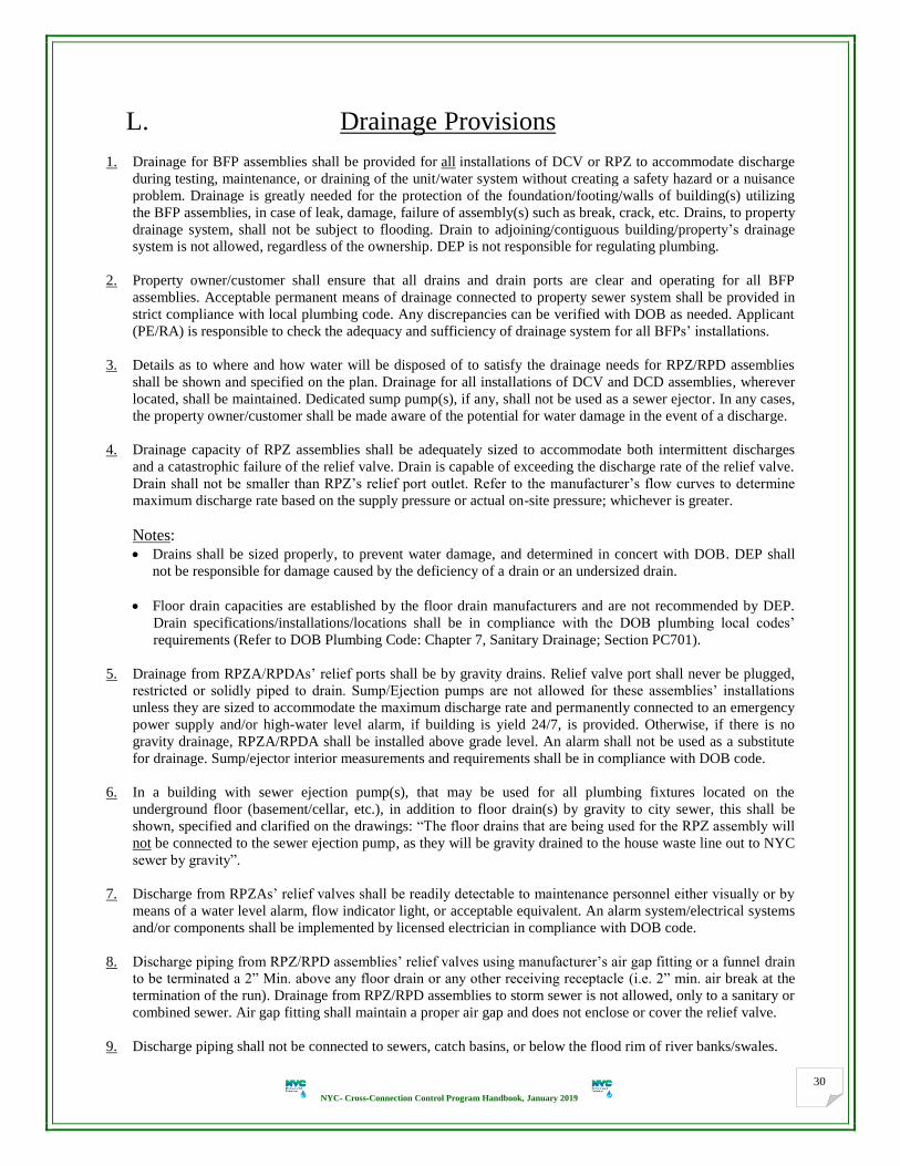
NYC- Cross-Connection Control Program Handbook, January 2019
30
L. Drainage Provisions
1. Drainage for BFP assemblies shall be provided for all installations of DCV or RPZ to accommodate discharge
during testing, maintenance, or draining of the unit/water system without creating a safety hazard or a nuisance
problem. Drainage is greatly needed for the protection of the foundation/footing/walls of building(s) utilizing
the BFP assemblies, in case of leak, damage, failure of assembly(s) such as break, crack, etc. Drains, to property
drainage system, shall not be subject to flooding. Drain to adjoining/contiguous building/property’s drainage
system is not allowed, regardless of the ownership. DEP is not responsible for regulating plumbing.
2. Property owner/customer shall ensure that all drains and drain ports are clear and operating for all BFP
assemblies. Acceptable permanent means of drainage connected to property sewer system shall be provided in
strict compliance with local plumbing code. Any discrepancies can be verified with DOB as needed. Applicant
(PE/RA) is responsible to check the adequacy and sufficiency of drainage system for all BFPs’ installations.
3. Details as to where and how water will be disposed of to satisfy the drainage needs for RPZ/RPD assemblies
shall be shown and specified on the plan. Drainage for all installations of DCV and DCD assemblies, wherever
located, shall be maintained. Dedicated sump pump(s), if any, shall not be used as a sewer ejector. In any cases,
the property owner/customer shall be made aware of the potential for water damage in the event of a discharge.
4. Drainage capacity of RPZ assemblies shall be adequately sized to accommodate both intermittent discharges
and a catastrophic failure of the relief valve. Drain is capable of exceeding the discharge rate of the relief valve.
Drain shall not be smaller than RPZ’s relief port outlet. Refer to the manufacturer’s flow curves to determine
maximum discharge rate based on the supply pressure or actual on-site pressure; whichever is greater.
Notes: Drains shall be sized properly, to prevent water damage, and determined in concert with DOB. DEP shall
not be responsible for damage caused by the deficiency of a drain or an undersized drain.
Floor drain capacities are established by the floor drain manufacturers and are not recommended by DEP.
Drain specifications/installations/locations shall be in compliance with the DOB plumbing local codes’
requirements (Refer to DOB Plumbing Code: Chapter 7, Sanitary Drainage; Section PC701).
5. Drainage from RPZA/RPDAs’ relief ports shall be by gravity drains. Relief valve port shall never be plugged,
restricted or solidly piped to drain. Sump/Ejection pumps are not allowed for these assemblies’ installations
unless they are sized to accommodate the maximum discharge rate and permanently connected to an emergency
power supply and/or high-water level alarm, if building is yield 24/7, is provided. Otherwise, if there is no
gravity drainage, RPZA/RPDA shall be installed above grade level. An alarm shall not be used as a substitute
for drainage. Sump/ejector interior measurements and requirements shall be in compliance with DOB code.
6. In a building with sewer ejection pump(s), that may be used for all plumbing fixtures located on the
underground floor (basement/cellar, etc.), in addition to floor drain(s) by gravity to city sewer, this shall be
shown, specified and clarified on the drawings: “The floor drains that are being used for the RPZ assembly will
not be connected to the sewer ejection pump, as they will be gravity drained to the house waste line out to NYC
sewer by gravity”.
7. Discharge from RPZAs’ relief valves shall be readily detectable to maintenance personnel either visually or by
means of a water level alarm, flow indicator light, or acceptable equivalent. An alarm system/electrical systems
and/or components shall be implemented by licensed electrician in compliance with DOB code.
8. Discharge piping from RPZ/RPD assemblies’ relief valves using manufacturer’s air gap fitting or a funnel drain
to be terminated a 2” Min. above any floor drain or any other receiving receptacle (i.e. 2” min. air break at the
termination of the run). Drainage from RPZ/RPD assemblies to storm sewer is not allowed, only to a sanitary or
combined sewer. Air gap fitting shall maintain a proper air gap and does not enclose or cover the relief valve.
9. Discharge piping shall not be connected to sewers, catch basins, or below the flood rim of river banks/swales.

NYC- Cross-Connection Control Program Handbook, January 2019
31
10. No reduction shall be made in the size of the relief port drain line. Air gap drain fitting/funnel drain is designed
to funnel relief valve discharge safely and positively to a drain (shall not be objectionable).
11. Drain line below air gap fitting or funnel drain can be any acceptable standard piping material. Sizes of air gap
fitting, or equivalent funnel and underneath drain lines are similar. Sizes of drain lines shall be specified on
drawings.
12. An air gap shall be maintained between the RPZA’s relief valve opening and any receiving discharge piping.
The air gap shall be at least twice the dimension of the effective opening of the valve; but in no case, shall an air
gap be less than two (2) inches.
13. Discharge piping connected to a house sanitary or combined sewer shall be trapped (P-trap) and equipped with
a backwater check valve (BWV), in compliance with EPA and DOB code. The connection shall be to house
sewer before house trap or to the house standpipe sewer (soil stack). Note: BWV shall be used for gravity flow
and be cleaned regularly. (Refer to DOB Plumbing Code: Chapter 8, Indirect Wastes; Section 802.2).
(2” min. air break on top of floor or pit with drain) P-Trap
Note: “S” trap is not approved. Water filling the downstream vertical portion of the S trap will cause siphoning
and loss of trap seals. Trap seals shall be maintained to prevent sewer gases and vermin from entering the
building.
14. The PE/RA shall verify if house trap pit drains to a dry well. The drain shall be connected to house sewer
connection before the house trap. A house trap (cleanouts) cannot be used as a floor drain as it should be tightly
plugged to prevent gases and vermin from entering the building. Indirect drain (waste) shall discharge to the
house drainage system. (See item 17). Fresh air intake (FAI) vents cannot be used as a mean of drainage.
15. For Port Authority of New York and New Jersey/Metropolitan Transit Authority (MTA)/ John F. Kennedy
Airport (JFK), or alike (in accordance with DOB plumbing code):
“Spilling of the water drain from the BFP assemblies, can be within the property lines in an area with low or no
pedestrian traffic. This area is not within the DOB’s jurisdiction”. No RPZ drainage ends up in catch basins.
16. Discharge piping from RPZAs’ relief valves shall be terminated above grade in an area not subject to flooding
(generally 1’ above the 100-year flood elevation). The terminal end of the discharge piping shall be equipped
with a rodent screen and should be supported by a headwall (lower rim 6” min. above grade). Flap valves
should also be considered to prevent entry of cold air as deemed necessary. No drainage ends up in catch basins.
17. All exterior drains that shall be kept free of ice and snow during cold temperatures are not allowed unless
approved by DOB. Exterior drains; inside the property; to back yards, gravel or grass areas may be acceptable
and are subject to approval by DOB as well. Drain piping/port/opening through fire-proof wall is not allowed.
18. RPZ/RPD assemblies shall not be installed in any areas subject to possible flooding. This includes pits or vaults
which are not provided with a gravity drain to the ground’s surface that is capable of exceeding the discharge
rate of the relief valve. This is relevant to the fact that all BFP assemblies shall not be subject to flooding.
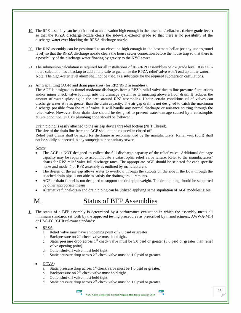
NYC- Cross-Connection Control Program Handbook, January 2019
32
19. The RPZ assembly can be positioned at an elevation high enough in the basement/cellar/etc. (below grade level)
so that the RPZA discharge nozzle clears the sidewalk exterior grade so that there is no possibility of the
discharge water ever blocking the RPZA discharge nozzle.
20. The RPZ assembly can be positioned at an elevation high enough in the basement/cellar (or any underground
level) so that the RPZA discharge nozzle clears the house sewer connection before the house trap so that there is
a possibility of the discharge water flowing by gravity to the NYC sewer.
21. The submersion calculation is required for all installations of RPZ/RPD assemblies below grade level. It is an 8-
hours calculation as a backup to add a fails-safe to guarantee the RPZA relief valve won’t end up under water.
Note: The high-water level alarm shall not be used as a substitute for the required submersion calculations.
22. Air Gap Fitting (AGF) and drain pipe sizes (for RPZ/RPD assemblies): The AGF is designed to funnel moderate discharges from a RPZ’s relief valve due to line pressure fluctuations
and/or minor check valve fouling, into the drainage system or terminating above a floor drain. It reduces the
amount of water splashing in the area around RPZ assemblies. Under certain conditions relief valves can
discharge water at rates greater than the drain capacity. The air gap drain is not designed to catch the maximum
discharge possible from the relief valve. It will handle any normal discharge or nuisance spitting through the
relief valve. However, floor drain size should be designed to prevent water damage caused by a catastrophic
failure condition. DOB’s plumbing code should be followed.
Drain piping is easily attached to the air gap device threaded bottom (NPT Thread).
The size of the drain line from the AGF shall not be reduced or closed off.
Relief vent drains shall be sized for discharge as recommended by the manufacturers. Relief vent (port) shall
not be solidly connected to any sump/ejector or sanitary sewer.
Notes:
The AGF is NOT designed to collect the full discharge capacity of the relief valve. Additional drainage
capacity may be required to accommodate a catastrophic relief valve failure. Refer to the manufacturers’
charts for RPZ relief valve full discharge rates. The appropriate AGF should be selected for each specific
make and model # of RPZ assembly as outlined by manufacturers.
The design of the air gap allows water to overflow through the cutouts on the side if the flow through the
attached drain pipe is not able to satisfy the drainage requirements.
AGF or drain funnel is not designed to support the drainpipe weight. The drain piping should be supported
by other appropriate means.
Alternative funnel-drain and drain piping can be utilized applying same stipulation of AGF modules’ sizes.
M. Status of BFP Assemblies
1. The status of a BFP assembly is determined by a performance evaluation in which the assembly meets all
minimum standards set forth by the approved testing procedures as prescribed by manufacturers, AWWA-M14
or USC-FCCCHR relevant standards:
RPZA:
a. Relief valve must have an opening point of 2.0 psid or greater.
b. Backpressure on 2nd
check valve must hold tight.
c. Static pressure drop across 1st check valve must be 5.0 psid or greater (3.0 psid or greater than relief
valve opening point).
d. Outlet shut-off valve must hold tight.
e. Static pressure drop across 2nd
check valve must be 1.0 psid or greater.
DCVA:
a. Static pressure drop across 1st check valve must be 1.0 psid or greater.
b. Backpressure on 2nd
check valve must hold tight.
c. Outlet shut-off valve must hold tight.
d. Static pressure drop across 2nd
check valve must be 1.0 psid or greater.

NYC- Cross-Connection Control Program Handbook, January 2019
33
2. RPZA/RPDA shall provide a minimum of: A 5.0 PSI static pressure drop across 1st check valve and 2.0 PSI
static pressure drop across relief valve.
3. A RPZA uses a stiffer 1st check valve spring in the main line assembly than is utilized in a DCV assembly. This
is to create enough of a pressure drop across the check valve for proper operation of the relief valve. Therefore,
the 1ST
check valve spring will not be interchangeable with the 2nd
check valve spring, contrary to the normal
practice for a double check valve assembly.
4. Once a containment assembly (external only) has been approved and installed, the plumber should review the
initial testing requirements with each customer, including frequency of testing (a yearly test shall be considered
a minimum), and how to report the testing results. The NYC Test and Maintenance of Backflow Prevention
Assembly Form GEN215B shall be used. [ http://www.nyc.gov/html/dep/pdf/water_sewer/10.pdf ]
5. BFP assemblies shall be tested immediately after installation and at least once a year thereafter. If a serious
defect is detected at the time of the first installation, the assembly should be promptly repaired or replaced. BFP
assemblies should be rebuilt or overhauled every five (5) years, after the initial installations, as per DOH
recommendation. All new metering shall be filed with BCS prior to testing any BFP assembly. Pending or
rejected plans shall render the initial test report(s) unacceptable when utilizing previously approved plans.
6. BFP assemblies required to be tested annually (on the due date) will be at the customer’s expense and results
forwarded to DEP on a NYC Form GEN215B. A BFP assembly that fails a test or does not meet the standards
is required to be repaired or replaced by the property owner/customer to correct any deficiencies or problems
with the assembly. The customer shall be responsible for any and all repairs/overhauls/replacement necessary to
maintain proper working condition of BFP assembly. All tests shall be performed by a NYS certified BFP
assembly tester who holds all proper licensing under NYS law regarding backflow testing.
7. Existing containment BFP assemblies shall be allowed to remain in service provided that they:
Meet the definition of assembly and the installation criteria required by NYS-DOH and DEP. See P.38.
Are deemed adequate and effective for the on-premises degree of assessed hazard and legalized by DEP.
Are in good working condition and functioning properly with cut valves in a workable position.
Maintain approved setting up, size and clearances, along with metering fixtures (if deemed acceptable).
Are testable and readily accessible in a safe location with drainage system, and not subject to flooding.
Have information readable (size, type, make and model #; in full; and serial #).
Have records of all periodic testing and maintenance (deemed passed) available with DEP.
Note: installation of BFP assembly inside of a locked property or in an unconventional location is prohibited.
8. Any existing backflow preventer shall be allowed to remain in service unless the degree of hazard is such as to
supersede the effectiveness of the present BFP or result in an unacceptable risk to the public health. Where
the degree of hazard has increased, as in the case of a residential installation converting to a hazardous business
establishment, any existing BFP assembly shall be upgraded to RPZ assembly, or RPZ assembly shall be
installed in the event that no BFP assembly is present.
9. Decommission/Swap of RPZ assembly:
In General: BFP assemblies shall not be by-passed, made ineffective/inoperative, or removed without prior
authorization from DEP. Renovation that may lead to swapping the RPZA shall be justified in detail.
A property having no auxiliary (untreated) water system is eligible to decommission the containment RPZ
assembly that may not be required by current DEP regulations and local codes provided that:
A PE/RA shall inspect the customer’s plumbing system(s), to confirm that no cross-connections are
present, and submit an elaborated decommission report and plans on the BFP assembly will be physically
replaced with proper containment that is deemed adequate and effective for the ongoing degree of hazard.
The property shall be surveyed by DEP authorized inspectors to determine the presence and prevalence of
potential hazards to ensure the water system protection is in accordance with the Program requirements.
10. All BFP assemblies have been evaluated with a specific set of shut-off valves, on both ends, as an integral part
of the assembly. The use or replacement of BFP shut-off valve other than those USC listed, invalidates the
USC-FCCCHR approval. BFP assembly’s inlet and outlet shut-off control valves are not interchangeable.
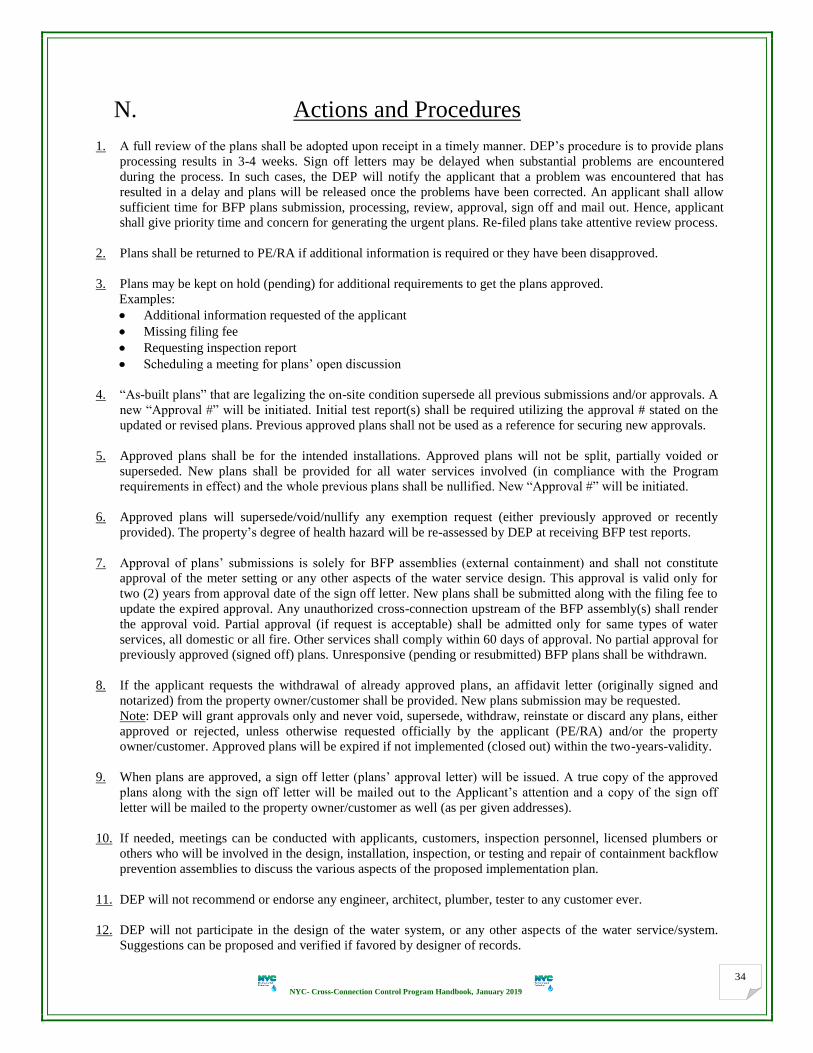
NYC- Cross-Connection Control Program Handbook, January 2019
34
N. Actions and Procedures
1. A full review of the plans shall be adopted upon receipt in a timely manner. DEP’s procedure is to provide plans
processing results in 3-4 weeks. Sign off letters may be delayed when substantial problems are encountered
during the process. In such cases, the DEP will notify the applicant that a problem was encountered that has
resulted in a delay and plans will be released once the problems have been corrected. An applicant shall allow
sufficient time for BFP plans submission, processing, review, approval, sign off and mail out. Hence, applicant
shall give priority time and concern for generating the urgent plans. Re-filed plans take attentive review process.
2. Plans shall be returned to PE/RA if additional information is required or they have been disapproved.
3. Plans may be kept on hold (pending) for additional requirements to get the plans approved.
Examples:
Additional information requested of the applicant
Missing filing fee
Requesting inspection report
Scheduling a meeting for plans’ open discussion
4. “As-built plans” that are legalizing the on-site condition supersede all previous submissions and/or approvals. A
new “Approval #” will be initiated. Initial test report(s) shall be required utilizing the approval # stated on the
updated or revised plans. Previous approved plans shall not be used as a reference for securing new approvals.
5. Approved plans shall be for the intended installations. Approved plans will not be split, partially voided or
superseded. New plans shall be provided for all water services involved (in compliance with the Program
requirements in effect) and the whole previous plans shall be nullified. New “Approval #” will be initiated.
6. Approved plans will supersede/void/nullify any exemption request (either previously approved or recently
provided). The property’s degree of health hazard will be re-assessed by DEP at receiving BFP test reports.
7. Approval of plans’ submissions is solely for BFP assemblies (external containment) and shall not constitute
approval of the meter setting or any other aspects of the water service design. This approval is valid only for
two (2) years from approval date of the sign off letter. New plans shall be submitted along with the filing fee to
update the expired approval. Any unauthorized cross-connection upstream of the BFP assembly(s) shall render
the approval void. Partial approval (if request is acceptable) shall be admitted only for same types of water
services, all domestic or all fire. Other services shall comply within 60 days of approval. No partial approval for
previously approved (signed off) plans. Unresponsive (pending or resubmitted) BFP plans shall be withdrawn.
8. If the applicant requests the withdrawal of already approved plans, an affidavit letter (originally signed and
notarized) from the property owner/customer shall be provided. New plans submission may be requested.
Note: DEP will grant approvals only and never void, supersede, withdraw, reinstate or discard any plans, either
approved or rejected, unless otherwise requested officially by the applicant (PE/RA) and/or the property
owner/customer. Approved plans will be expired if not implemented (closed out) within the two-years-validity.
9. When plans are approved, a sign off letter (plans’ approval letter) will be issued. A true copy of the approved
plans along with the sign off letter will be mailed out to the Applicant’s attention and a copy of the sign off
letter will be mailed to the property owner/customer as well (as per given addresses).
10. If needed, meetings can be conducted with applicants, customers, inspection personnel, licensed plumbers or
others who will be involved in the design, installation, inspection, or testing and repair of containment backflow
prevention assemblies to discuss the various aspects of the proposed implementation plan.
11. DEP will not recommend or endorse any engineer, architect, plumber, tester to any customer ever.
12. DEP will not participate in the design of the water system, or any other aspects of the water service/system.
Suggestions can be proposed and verified if favored by designer of records.

NYC- Cross-Connection Control Program Handbook, January 2019
35
4. DEP POLICIES
The primary federal statute governing the safety of PWSs in the United States is “SDWA”.
The Federal Safe Drinking Water Act (SDWA) of 1974, as amended in 1986 and again in 1996, and Part
5 of the NYS Sanitary Code, Subpart 5-1 Public Water Supplies, Section 5-1.31, states that the water
supplier has the primary responsibility to protect the public water system by containing potential
contamination within the premises of the customer through cross-connection control by containment.
Containment (which is DEP concern) is also referred to as service protection or premises isolation: Containment means cross-connection control which isolates the customer’s entire facility from the public
water system (protection at connections to CWMs) so as to provide the protection necessary to prevent
contamination/pollution of the public water supply in the event of backflow from the customer’s property.
OBJECTIVE The objective of DEP is to assure the safety of water delivered to all users. An active, ongoing effort to
eliminate or control cross-connections is necessary under all foreseeable circumstances. It is, therefore,
imperative that everything possible be done to protect against the degradation of water quality within the
distribution system. To maintain and accomplish this objective, the following continuing program goals
of DEP are designed to systematically and effectively control all actual and potential cross-connections.
A. Types of Water Service Connections
B. Types of BFP Assemblies Installations
C. BFP Assemblies Installation Criteria
I. AIR GAP
II. RPZA
III. DCVA
IV. DCDA
V. RPDA
D. Plan Review Process
1. Application Form NYC GEN236
2. Plot Plan (Site Plan)
3. Elevation View (Riser Plan)
4. Plan View (Floor Plan)
5. Time Calculation before RPZA/RPDA Floods

NYC- Cross-Connection Control Program Handbook, January 2019
36
A. Types of Water Service Connections

NYC- Cross-Connection Control Program Handbook, January 2019
37
B. Types of BFP Assemblies Installations
Single Line:
→F or, →F
“RPZA” “DCVA”
■□■□■□■□■□■□■□■□■□■□■□■□■□■□■□■□■□■□■□■□■□■□■□■□■□■□
Dual, Triple, etc. (Manifold): Parallel installations (continuous water service) are effective means of insuring uninterrupted water service and
strongly recommended when requiring such continuity:
Where continuous flow is required during BFP assembly servicing or testing:
Then, 2 or more BFP assemblies connected in parallel will be required (followed by T.T. & MOCV each).
Where multiple service lines are required to feed multiple tenants:
Then, 2 or more BFP assemblies connected in parallel will be required (followed by T.T. & MOCV each).
Each such service line shall have that BFP assembly for the service line having the highest degree of hazard.
Note: The combined flow rate (total capacity) of the assemblies shall equal or exceed the flow rate of a single
assembly setting that is required by the system. Interconnection downstream of the HCVs or the water meters
(either existing or proposed, if approved); to one assembly; is not allowed as it loops the water main(s) and
destroys the effectiveness of the parallel installation. Interconnection shall be downstream of MOCVs or the
BFP assemblies (DCDA/RPDA) on the fire protection services, if required. See P. 68 for more details.
RPZAs or, DCVAs
RPZAs or, RPZAs
■□■□■□■□■□■□■□■□■□■□■□■□■□■□■□■□■□■□■□■□■□■□■□■□■□■□
Tandem (Separate Lines):
All lines shall be equally protected and as degree of health hazard shall dictate ↓
Master
Meter Master
Meter
Master
Meter
Ex. Master Meters
Master
Meter Master
Meter
Master Meter
Control Valves
Master Meter

NYC- Cross-Connection Control Program Handbook, January 2019
38
C. BFP Assemblies Installation Criteria (Advantages and Limitations)
BFP assemblies shall be installed horizontally in an upright position. Only BFP assemblies approved for
vertical installation by USC-FCCCHR, including the proper direction of flow, can be installed vertically.
I. AIR GAP (AG):
It shall meet the definition of an air gap. It provides maximum protection from backflow hazards and may
be utilized at premises where the substance which may backflow is hazardous to health.
It shall be at least twice the diameter of the supply pipeline measured vertically above the flood rim of the
receiving receptacle, but in no case less than one (1) inch. (See P. 80 and 91).
It shall be located as close as practical between the premises water connection and the receiving tank.
It shall not be altered or defeated without pre-approval of DEP and shall be accessible for inspection at all
reasonable times. It shall be subject to the same testing rules required for all other BFP assemblies.
Using hoses or a by-pass that entirely destroys the effectiveness of an AG, is not allowed.
II. RPZA:
RPZA shall be utilized at premises where the substance which may backflow is hazardous to health. The RPZA is
normally used in locations where an air gap is impractical and is effective against both backsiphonage and
backpressure. Head loss through the assembly ranges between 10 and 30 psi depending on the size and flow rate.
RPZ shall be sized hydraulically to provide an adequate supply of water and pressure for the premises being served.
Flow characteristics and manufacturer’s specifications for specific performance data shall be considered.
Property where interruption of the water demand is critical should be provided with two similar assemblies installed
in parallel. They should be sized hydraulically in such a manner that either assembly will provide the minimum
water requirements while the two together will provide the maximum flow required.
Bypass lines are not permitted. Pipe fittings which may be used for connecting a bypass line shall not be installed.
Water service lines should be thoroughly flushed prior to assembly installation, to minimize mechanical damage.
RPZA shall be readily accessible for in-line testing and maintenance and shall be located in an area where water
damage to building or furnishings would not occur from relief valve discharge. An approved air gap fitting, or
funnel will be used to direct minor discharges away from the assembly. The air gap funnel will not control flow in a
continuous relief situation. Drain lines to accommodate full relief valve discharge flow should be considered. Relief
vents shall not be reduced, plugged or extended (piping affixed to the pressure differential relief valve port). RPZAs
shall be installed with the relief vent pointed down. The property owner/customer shall be made aware of all
responsibility for foundation or basement wall penetration, leaks and damage.
RPZAs are typically installed above grade in well drained areas but may be installed below grade if an adequate
daylight drain and sufficient submersion calculation are provided. Spillage shall not be objectionable.
The RPZA shall be installed above the 100-year flood plain elevation. RPZAs shall not be installed in a vault or pit. The RPZA shall be protected from freezing and other severe weather conditions. Enclosures shall be designed for
easy access and sized to allow for the minimum clearances. Daylight drain port shall be provided to accommodate
full pressure discharge from the RPZA.
Maximum height of installation:
from centerline to tread floor shall not exceed 5 feet, with no interception(s),

NYC- Cross-Connection Control Program Handbook, January 2019
39
from hand wheels of shut-off valves to tread floor shall not exceed 5.5 feet, unless there is a permanently
installed platform meeting OSHA standards to facilitate servicing the assembly.
All RPZAs shall be tested upon installation and at least once per year thereafter by an approved NYS certified tester
to ensure that: both check valves are drip-tight under all pressure differentials; and the pressure differential relief
valve will maintain pressure in the center chamber of at least two (2) psi below that of the inlet chamber. Records of
such tests and repairs will be maintained by DEP, and it is the responsibility of any BFP assembly tester performing
tests and maintenance to submit records of such tests and repairs to DEP.
Variances from these regulations will be evaluated on a case by case basis. Any deviations shall have prior written
approval of DEP.
III. DCVA:
DCVAs shall be installed at premises where the substance which may backflow is objectionable but not hazardous
to health. If a health hazard condition does not exist in the property, installation of a DCVA in lieu of RPZA is
permissible. DCVA is the minimum type of backflow protection required to protect the city water main. The head
loss through the assembly ranges between 3 and 11 psi, depending on the size and flow rate of the assembly.
DCVA shall be sized hydraulically to provide an adequate supply of water and pressure for the premises being
served. Flow characteristics and manufacturer’s specifications for specific performance data can be considered.
DCVA shall be located directly downstream of the master water meter.
Property where an interrupted flow of water is critical should be provided with two similar assemblies installed in
parallel. They should be sized hydraulically in such a manner that either assembly will provide the minimum water
requirements while the two together will provide the maximum flow required.
Bypass lines are not permitted. Pipe fittings which may be used for connecting a bypass line shall not be installed.
Water service lines should be thoroughly flushed prior to assembly installation, to minimize mechanical damage.
DCVA shall be readily accessible with adequate room for in-line testing and maintenance.
DCVA shall not be installed in a pit of potential for flooding, confined space entry and other safety concerns.
DCVAs may be installed below grade in a vault, provided water-tight brass or plastic plugs are installed on the test
cocks. The assembly shall not, however, be subject to immersion. All vaults shall be well drained, meet vault
standards, and be sized to allow for the minimum clearances to facilitate disassembly, repair and testing. The owner
shall also verify that the vault is kept reasonable free of silt and debris. Check vault installations’ regulations.
Maximum height of installation:
from centerline to tread floor shall not exceed 5 feet, with no interception(s),
from hand wheels of shut-off valves to tread floor shall not exceed 5.5 feet, unless there is a permanently
installed platform meeting OSHA standards to facilitate servicing the assembly.
DCVA can be installed vertically as well as horizontally provided that the assembly is approved for vertical
installation by USC-FCCCHR, including the proper direction of flow.
DCVA shall be protected from freezing and other severe weather condition.
The property owner/customer shall be made aware of all responsibility for foundation or basement wall penetration,
leaks, and damage.
All DCVAs shall be tested upon installation and at least once per year thereafter by an approved NYS certified tester
to ensure that both check valves are drip-tight under all pressure differentials. Records of such tests and repairs will
be maintained by DEP, and it is the responsibility of any BFP assembly tester performing tests and maintenance to
submit records of such tests and repairs to DEP.
Variances from these regulations will be evaluated on a case by case basis. Any deviations shall have prior written
approval of DEP.

NYC- Cross-Connection Control Program Handbook, January 2019
40
IV. DCDA:
DCDAs shall be utilized in all installations requiring a double check valve assembly and detector metering (that
allows the visual inspection of flow through the assembly) on fire protection services only. Bypass meters for
DCDAs shall be USC-FCCCHR approved. DCDAs shall comply with the installation requirements applicable for
DCV assemblies which maintain the assemblies’ Foundation Approval.
V. RPDA:
RPDAs shall be utilized in all installations requiring a reduced pressure backflow assembly and detector metering on
fire protection services only. Bypass meter for RPDAs shall be USC-FCCCHR approved. RPDAs shall comply with
the installation requirements applicable for RPZ assemblies which maintain the assemblies’ Foundation Approval.
Note: RPDAs are not acceptable for the vertical orientation unless approved and listed by USC-FCCCHR.
D. Plan Review Process Plans and specifications for the backflow prevention installation shall be submitted to DEP for approval prior to the
installation of the BFP assembly to ensure all requirements are met and avoid the unnecessary expenses. (Plans will not be approved until presentation of all required documents and information are reviewed and approved)
(Applicant should keep ALL marked-up plans during the review process until the plan has been approved)
1. Application Form NYC GEN236 The applicant most follows the instructions on the back of the Application Form (See P. 53).
Applicant shall verify the actual address of the related property (for the areas of the City of NY):
Where the water service comes in and the water meter or meter setting located, no matter what it feeds.
To be as specific as possible along with the related Block and Lot numbers, tentative lot (if any) to coincide
with NYC DOF and DOB records. “AKA” address to be specified as well, either existing or new facilities.
In a lot that maintains multiple addresses; stores, buildings, etc.; shall provide the address as specified on
DOF records (as a leading address).
When locations/properties have no specific profile (Address/Block #/Lot #):
A temporary Block # and Lot # will be created and provided by DEP and shall be kept upon request and
utilized, by customers, on all submissions and test reports (either initial or annuals).
MTA: specific address, block and lot #s (if any) or the location tracking #.
Parks, JFK, Bridges, Tunnels, Temporary Sites, and alike: specific address (if any) or actual locations with
cross streets.
Example: St. Johns Avenue between 10th
Street and 11th
Street, Intersection of ----- Street and ------ Avenue.
New Developments/Compounds (for multiple addresses and lot #s) that requires IWM: a leading address
with the related lot # shall be provided.
2. Plot Plan (Site Plan)
The plot plan shall be consistent with the updated records of DOB, DOF, Digital Tax Map (DTM), Oasis Map, etc.
It shall show/identify the following information:
Name of the project, if any.
Site plan for the entire lot (all facilities/stores/buildings footprints) with the closed property line. Clear vicinity
map to location of project. Key map for the site location, if any.
Dimensions of the lot (lay out diagram), distance to corner street intersection, to verify state: existing or new,
the combination (merging), reapportionment or sub-division of lot(s). Tentative lot(s) shall be specified.
All streets fronting the lot/cross streets and site designations (water front areas, flood hazard area, etc.), if any.
North arrow.
Mains, and all water service lines (existing & new), specifying state (existing or new), type (material) and size.
An exempted domestic water service shall be identified. Previously approved water service(s), if any.
Type of water service connection (house connection): Domestic water service , Fire Sprinkler (SP) service, Fire
Standpipe (SD) service, Combination Fire SP/SD service, Combined water service (Domestic with Fire SP
and/or SD take off), Combined water service (Fire SP and/or SD with Domestic take off). See Sketch, P. 36.
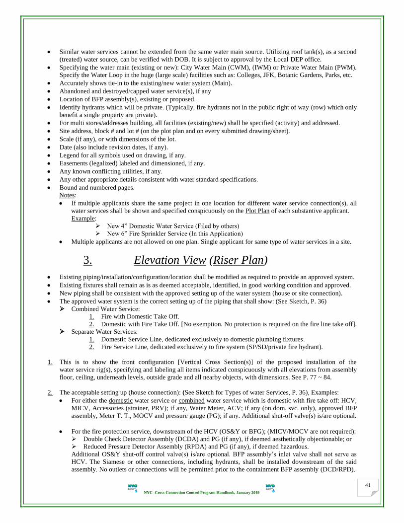
NYC- Cross-Connection Control Program Handbook, January 2019
41
Similar water services cannot be extended from the same water main source. Utilizing roof tank(s), as a second
(treated) water source, can be verified with DOB. It is subject to approval by the Local DEP office.
Specifying the water main (existing or new): City Water Main (CWM), (IWM) or Private Water Main (PWM).
Specify the Water Loop in the huge (large scale) facilities such as: Colleges, JFK, Botanic Gardens, Parks, etc.
Accurately shows tie-in to the existing/new water system (Main).
Abandoned and destroyed/capped water service(s), if any
Location of BFP assembly(s), existing or proposed.
Identify hydrants which will be private. (Typically, fire hydrants not in the public right of way (row) which only
benefit a single property are private).
For multi stores/addresses building, all facilities (existing/new) shall be specified (activity) and addressed.
Site address, block # and lot # (on the plot plan and on every submitted drawing/sheet).
Scale (if any), or with dimensions of the lot.
Date (also include revision dates, if any).
Legend for all symbols used on drawing, if any.
Easements (legalized) labeled and dimensioned, if any.
Any known conflicting utilities, if any.
Any other appropriate details consistent with water standard specifications.
Bound and numbered pages.
Notes:
If multiple applicants share the same project in one location for different water service connection(s), all
water services shall be shown and specified conspicuously on the Plot Plan of each substantive applicant.
Example:
New 4” Domestic Water Service (Filed by others)
New 6” Fire Sprinkler Service (In this Application)
Multiple applicants are not allowed on one plan. Single applicant for same type of water services in a site.
3. Elevation View (Riser Plan)
Existing piping/installation/configuration/location shall be modified as required to provide an approved system.
Existing fixtures shall remain as is as deemed acceptable, identified, in good working condition and approved.
New piping shall be consistent with the approved setting up of the water system (house or site connection).
The approved water system is the correct setting up of the piping that shall show: (See Sketch, P. 36)
Combined Water Service:
1. Fire with Domestic Take Off.
2. Domestic with Fire Take Off. [No exemption. No protection is required on the fire line take off].
Separate Water Services:
1. Domestic Service Line, dedicated exclusively to domestic plumbing fixtures.
2. Fire Service Line, dedicated exclusively to fire system (SP/SD/private fire hydrant).
1. This is to show the front configuration [Vertical Cross Section(s)] of the proposed installation of the
water service rig(s), specifying and labeling all items indicated conspicuously with all elevations from assembly
floor, ceiling, underneath levels, outside grade and all nearby objects, with dimensions. See P. 77 ~ 84.
2. The acceptable setting up (house connection): (See Sketch for Types of water Services, P. 36), Examples:
For either the domestic water service or combined water service which is domestic with fire take off: HCV,
MICV, Accessories (strainer, PRV); if any, Water Meter, ACV; if any (on dom. svc. only), approved BFP
assembly, Meter T. T., MOCV and pressure gauge (PG); if any. Additional shut-off valve(s) is/are optional.
For the fire protection service, downstream of the HCV (OS&Y or BFG); (MICV/MOCV are not required):
Double Check Detector Assembly (DCDA) and PG (if any), if deemed aesthetically objectionable; or
Reduced Pressure Detector Assembly (RPDA) and PG (if any), if deemed hazardous.
Additional OS&Y shut-off control valve(s) is/are optional. BFP assembly’s inlet valve shall not serve as
HCV. The Siamese or other connections, including hydrants, shall be installed downstream of the said
assembly. No outlets or connections will be permitted prior to the containment BFP assembly (DCD/RPD).

NYC- Cross-Connection Control Program Handbook, January 2019
42
3. Specify all control valves: HCV, MICV, MOCV and additional SOV (if any): state, size and type.
Ex.: * New 3” HCV, OS& Y * New 2” MOCV, Ball Valve. * Existing 4” MOCV, OS&Y, etc.
4. Specify all accessories that may be located upstream of the master water meter either existing or proposed such
as: SOV, strainer and PRV, if any. PG is not allowed upstream of the meter or the fire BFP assembly.
5. Specify all accessories that may be located downstream of the master water meter either existing or proposed
such as: ACV (that prevents against costly flood damage), additional shut-off valve and such like, if any.
6. Specify all accessories that may be located downstream of the BFP assembly either existing or proposed such
as: trap seal primer, flushing blow-off, additional shut-off valve, etc. (if any).
7. Water Meter (and accessories) information shall be specified conspicuously:
State (existing or new).
Meter size, type, make and model (if any) and location.
Serial Number for the master meter and all sub-meters, if any, to each of the occupancies (tenants). What is
each meter covering? Serial # of the water meters are used for tracking the actual location of the pertaining
property, where the water service comes in.
MICV, meter T. T., MOCV and other accessories if any (Ex. PRV and/or approved flat plate strainer).
5x and 3x diameter of the straight piping shall be maintained before (with fully open valves and strainers
included in the measurement) and after the meter respectively for all meter installations in new construction
except for displacement meters, or pre-existing conditions. http://www.nyc.gov/html/dep/pdf/meterlist.pdf.
8. BFP assemblies shall be located on the property side of the master water meter, upstream of any connection
points to the water service line and shall be of the same size as meter or larger. In no case shall there be any
connections to the water service upstream of the BFP assembly. Buried/waste valves are not permitted.
9. Proposed BFP assemblies shall be USC-FCCCHR approved, currently produced/on the market, adequately
supported, and have shut-off valves [upstream shut-off valve (USSV) and downstream shut-off valve (DSSV)]
on both ends (as one assembly); all are indicated on the drawings. Shut-off gate valves shall be specified
conspicuously as no OS&Y valve for ball valve or butterfly gate valve (BFG/BG) and vice versa.
10. BFP assemblies shall be set as one assembly, no split, dislocation or reconfiguration to any part included, that
can invalidate the USC-FCCCHR approval of the whole assembly.
11. The water service shall have no outlets, tees, taps or connections of any sort between the POE/water meter and
the protective containment assembly. No by-pass or take off piping is permitted, upstream of the BFP assembly,
unless it is fitted with an assembly similar to the main line assembly as appropriate for the same hazard rating.
12. Same level of protection shall be utilized for all similar types of water service lines located in the same facility.
13. Specifying and labeling the actual location of the BFP assembly(s); i.e. Cellar, Sub-Cellar (number if any),
Basement, Pit, Vault, 1st Floor, 2
nd Floor, Hot Box, etc. Grade level shall be shown and specified how far to the
floor level where the BFP assembly is located.
14. If a domestic water service may be exempted as part of the submitted BFP plans: (See P. 63)
Two (2) sets of the exemption request shall be provided. Any exemption, approved or denied, will be done
so in writing and approval or denial letter will be issued to notify both applicant and property owner.
The exempted domestic water service shall be shown and specified on all shop drawings.
15. As a general rule, for installation of BFP assemblies, regardless of size, type, configuration, make and model #,
orientation and location of assembly (building, vault, hot box, etc.), the clearances shall maintain ranges of:
30” min. clearance space from centerline of the assembly to tread floor.
60” max. clearance space from centerline, or highest point (if in vertical) of the assembly to tread floor.
66” max. clearance space from hand-wheels of the shut-off valves of the assembly to tread floor.
18” min. clearance from lowest point (if in vertical), also the relief port of the large RPZ assembly to floor.

NYC- Cross-Connection Control Program Handbook, January 2019
43
12” Min. clearance space from highest point of the assembly to the ceiling or any obstruction.
Air gap separation between the RPZ’s relief port & the drain receptacle/funnel shall be Minimum of:
2” – for assembly size of 0.75” to 1”
3” – for assembly size of 1.25” to 1.50”
4” – for assembly size of 2” or larger
Note: Where the BFP assemblies are to be installed in an over and under arrangement (in tiers), both rigs shall
be subject to the above stipulation. Fixed ladder/platform (if any) shall not obstruct any assembly.
16. Drainage details for all installations of BFP assemblies shall be shown, specified and clarified conspicuously.
Destination of drainage system shall be shown. By way of example:
Existing/New 4” Floor Drain to house sewer connection, to City sewer by gravity.
Existing/New 6” Floor Drain to house sewer ejection pump, permanently wired to “emergency power
supply” (standby source, backup generator).
Existing/New 4” Floor Drain to house sewer ejection pump, with “high-water level alarm”.
Note: A high-water level alarm for leak (flow) detection shall be monitored 24/7 to alert maintenance security
or concierge personnel will be provided. Detector (Sensor) can be installed on the wall reasonably above the
finished floor, close to the RPZ/RPD assembly. The building shall have personnel supervision around the clock.
Detector can be connected to building monitor system (BMS), if any, annunciators, beacons, strobes, buzzers or
combination of any. The alarm shall not be used as a substitute for drainage or submersion calculations.
17. If RPZ assembly is required to be installed in an approved standard/quoted and sized protective enclosure:
It shall be above ground (in property), have suitable freeze protection (with electric heaters or heat trace
for any water service may be used year around), not subject to flooding, and be kept free from any debris.
It shall be installed on a sized concrete pad (slab), 6” minimum height revealed on grade; with dimensions.
The enclosure type (hot box), make and model #, with dimensions shall be specified on plans.
Approved enclosures use standard detail with provisions for natural or artificial light and drain ports.
Full flow gravity drain shall be emitted to the atmosphere above the flood plain elevation. The bore-sight
drain shall never be connected to sewer, catch basin, sumps, dry wells, etc.
Full opening hatch to much encompass centerline of assembly, providing adequate clearances around the
assembly to access the shut-off valves (handles to be concealed), check valves, test cocks and relief valve.
Provisions shall be made to protect the assembly from vandalism with security measures such as locking
doors and panel, flow alarms or flow indicator lights, power indicator lights, etc.
Note: Approved types of prefabricated insulated enclosures can be: “Hot Box” and Safe-T-Cover by
“HydroCowl” that provide heat, gravity drainage and removable access panels for servicing and testing.
Alternate wood frame, fiberglass, steel, masonry or precast concrete structure may be utilized. (See P. 77).
18. No RPZA/RPDA installation in pit/vault:
A RPZA can never be installed below grade in a pit or vault. Every manufacturer of USC-FCCCHR approved
RPZAs in the U.S. prohibits installation of this assembly below ground. If RPZ assembly is outside, vaults are
not allowed, and it would be better if water service goes unprotected. Consequently, RPZA shall be installed
inside a protective enclosure above grade level, within the property.
19. If an ACV (flood control), controlled by a Flow Switch (FS), Sensor, EST, MS, etc. is required upon the
Engineer’s request and/or the property owner’s discretion, it shall be installed between the master meter and
RPZ assembly. The property owner will be fully responsible for this additional control valve (installation, test,
maintenance and possible troubleshooting). This automatic control valve cannot be installed upstream of the
master water meter according to BCS rules, as no obstruction is allowed before the water meter. ACV is not
recommended or disfavored by DEP and shall not conflict with the DEP’s rules and regulations. (See P. 84).
20. If a PRV is required:
A PRV is usually recommended (either globe or angle style body) on domestic water systems whereas the water
supply pressure exceeds 80 PSI. A higher pressure may rupture piping and damage fixtures. Moreover, it
reduces the water consumption, saves energy and increases the system’s performance. PRV (Lead-Free type)
installation (typically upstream of the master water meter) is subject to approval by BCS.
NYC- Cross-Connection Control Program Handbook, January 2019
44
21. If trap seal primer is proposed (either recommended by PE/RA or required by DOB plumbing code), it shall be
set downstream of the containment BFP assembly (RPZ).
22. If RPZA/RPDA (2-1/2” size or larger) is installed below grade level (basement, cellar, etc.), time from full flow
failure to submersion of the relief port shall be no less than 8 Hours. Otherwise, assembly shall be installed on
the maximum possible height (maintaining the appropriate clearances) or elevated above grade level. See P. 47.
23. The height limitations for the installation of a RPZA/RPDA in N-pattern or Z-pattern shall maintain:
18” min. clearance space from the lowest point of the assembly to tread floor.
30” min. clearance space from centerline of the assembly to tread floor.
60” max. clearance space from centerline of the assembly (N-shape) or highest point of the assembly (Z-
shape) to floor provided that: an OSHA approved ladder or platform shall be provided if highest point of
assembly exceeds 60”.
12” min. clearance space from highest point of the assembly to the ceiling or any obstruction.
24. DCDA with by-pass meter on a dedicated fire service can be installed horizontally or vertically up-orientation.
DCDA can be equipped with OS&Y or BFG/BG (grooved end) shut-off control valves, indicating type only.
Consequently, the height limitations for the installation of a DCDA on a fire service shall be as follows:
a. DCDA, if installed horizontally (conventional in line), shall maintain the following limitations:
30” min. clearance space from centerline of the assembly to tread floor.
60” max. clearance space from centerline of the assembly to tread floor provided that an OSHA approved
ladder or platform shall be provided if centerline of the assembly exceeds 60” height and/or the hand
wheels of the shut-off valves exceed the 66” height.
12” min. clearance space from highest point of the assembly to the ceiling or any obstruction.
b. DCDA, if installed vertically (flow up orientation), shall maintain the following limitations:
18” min. clearance space from the lowest point of the assembly to tread floor.
30” min. clearance space from centerline of the assembly to tread floor.
30” min. clearance space on the front side of the by-pass to any obstruction.
30” min. clearance space from the most extended stem of the OS&Y shut-off valve to any obstruction.
60” max. clearance space from highest point of the assembly to tread floor provided that an OSHA
approved ladder or platform shall be provided if highest point of the assembly exceeds 60”.
8” min. clearance space from both back sides to the wall or any obstruction.
12” min. clearance space from highest point of the assembly to the ceiling or any obstruction.
c. DCDA can be in different configuration, N-Pattern or Z-Pattern, shall maintain the following limitations:
18” min. clearance space from the lowest point of the assembly to tread floor.
30” min. clearance space from centerline of the assembly to tread floor.
60” max. clearance space from centerline of the assembly (N) and highest point (Z) to floor provided
that an OSHA approved ladder or platform shall be provided if highest point of the assembly exceeds 60”.
30” min. clearance space on the front side of the by-pass to any obstruction.
30” min. clearance space from the most extended stem of the OS&Y shut-off valve to any obstruction.
8” min. clearance space from back side of the assembly to the wall or any obstruction.
12” min. clearance space from highest point of the assembly to the ceiling or any obstruction.
25. On the elevation view, if minimum height limitation from centerline of assembly is specified, so, maximum
height also shall be specified. Example: 30” Min., 48” Max. All specified dimensions shall not be in conflict.
Actual clearances shall be specified. No maximum or minimum height limitations for existing condition.
26. Attempts to modify a DCV assembly by adding a bypass line containing a meter and a small double check valve
assembly usually results in a unit that will not function properly. USC-FCCCHR cautions against attempts to
convert a DCV assembly to a DCD assembly and vice versa. USC-FCCCHR carefully evaluates each make,
model, and size before approving the units. Keeping up-to-date with the USC most current approved List is
crucial. All customers shall act in accordance with USC-FCCCHR command and meet their specified standards.
NYC- Cross-Connection Control Program Handbook, January 2019
45
27. DCDA/RPDA (Type I) usually maintains a bypass containing a water meter and approved exclusive DCV/RPZ
assembly specifically designed for such application. The bypass meter shall register accurately for very low
flow rates of flows up to 3 gallons per minute and shall register for all flow rates. Attempts to use/manipulate
this DCVA/RPZA on the by-pass as a substantive containment assembly is not approved and prohibited.
28. DCDA/RPDA requires greater horizontal clearance to allow adequate room for testing and maintenance of both
the mainline assembly and the bypass DCV/RPZ assemblies or the single check valve (SCV) in case of Type II.
29. BFP assemblies (DCV/RPZ/DCD/RPD) can be installed in a hot box above grade level either solely (stand-
alone) or with the whole rig, at the property or right-of-way boundary (i.e. easement); if any.
30. DCV or DCD assemblies can be installed in a pit or vault (in the property) provided that: (See P. 77/78)
Pits or vaults shall be constructed of impervious materials with manholes or access doors extending a
minimum of 6 inches above grade and located to allow natural light into the pit during testing and
maintenance. Vaults shall not be installed in any street/alley, parking area, driveway or sidewalk.
The pit can be uncovered and shall be readily accessible with no obstruction, large enough to bodily enter.
Constructed so that it will not flood, with adequate horizontal and vertical clearances to allow access to the
assembly. Pits or vaults shall vent to the atmosphere. Blow-offs, if any, shall be routed away above grade.
Pit shall be equipped with full flow screened drained. Floor shall be pitched to the drain.
The pit is designed with a sump and pump if subject to ground water accumulation.
Access stairway, ladder or step irons (meeting OSHA standards) and adequate natural or artificial lighting
shall be provided to facilitate maintenance, inspection and testing.
Crane access for installing and removing large assemblies, if need be.
Test cocks of BFP assemblies should be protected with watertight plugs (brass or plastic, non-ferrous).
Min. height of the vault is 6’-6”. (See Typical Meter Vault – RCNY Title 15, Chapter 20 – Figure 17).
Dual assemblies within the same location shall have full opening hatch to allow easy access from the
centerline of one assembly to centerline of the opposite assembly or any obstruction.
The pit has adequate ground cover to prevent freezing.
The pit has surface grading to divert runoff away from the entrance way.
Semi-buried pits or berm installations may be necessary to satisfy gravity drainage.
Insulation shall not restrict or cover up test cocks, shut-off valves or name plates on assembly.
All safety precautions should be applied scrupulously when entering confined spaces (OSHA standards).
31. In a building with an underground vault, extended along with the cellar floor under the sidewalk, the POE/POS
and curb valve shall be shown and specified along with the entire setting up of the water service. See P. 78.
32. Where it is not feasible to install the BFP assembly inside the building, it will be required to be installed at or
near the property line in a heated enclosure (hot box); above ground, or vault; underground.
33. In a building with existing roof tank(s) that may feed all domestic and/or fire systems, it shall be specified:
They are filled by the house pump(s) and equipped with an approved (safe) air gap separation.
There are no water connections to any fixtures in the building after the MOCV to the house pump(s).
All domestic plumbing fixtures and fire SP/SD system(s) are down fed directly from the roof tank(s). DCV
installation downstream of the master water meter is the minimum requirement. A water riser diagram,
thoroughly surveyed and approved by DOB, shall be provided. Otherwise, RPZ assembly shall be installed.
34. Legalization: As-built plans shall be provided similar to a new regular plan, along with filing fee, specifying the
on-site condition and labeling all items depicted on drawings as EXISTING with all other pertaining details:
Size, type of the water service connection(s).
Size and serial # of the meter(s), and all sub-meters (if any) and location, and by-pass meter on DCD/RPD.
Size, type, make, model #, and serial # of BFP assembly (main and by-pass assemblies on DCDA/RPDA).
Size, type of all control valves (HCV, MICV, Meter Test Tee and MOCV), and additional valves; if any.
All actual clearances, location (floor/level) of assembly and dimensions of limited spaces (rooms/closets).
RPZA/RPDA submersion computations, drainage details, etc. Adequate drainage for DCVA and DCDA.
Existing fixtures shall remain as is as deemed acceptable, identified and in good working condition.
NYC- Cross-Connection Control Program Handbook, January 2019
46
Notes:
Piping shall be modified in conformity with an approved system in full compliance with all rules and
regulations in effect. Existing BFP assembly(s) shall be commensurate with the current degree of hazard.
If the serial # or ID of any BFP assembly is unreadable (paint, scratch, etc.) or removed, a new name plate
with a new serial # can be created by the manufacturer only. Otherwise, new assembly shall be installed.
When an existing BFP assembly is restored to a water service after previously being removed service, the
assembly shall be tested upon restoration.
35. All BFP assemblies shall be adequately supported and/or restrained to prevent lateral movement. Supports shall
be placed where they will not obstruct the function of or access to RPZA/RPDA’s relief valve. Enclosures shall
be standard/quoted and sized according to either designer’s specifications or equipment located inside.
36. Specified dimensions/clearances on the drawings shall take precedence over scaled dimensions/clearances.
37. Plans (PE/RA signed and stamped originals) are consistent with information provided in all water services.
38. Clear space shall be maintained on plans for DEP approval stamps on all submitted sheets/drawings.
4. Plan View (Floor Plan)
1. Normally, this is to show the plumbing floor plan or partial floor plan specifying and labeling all items
indicated (entire setting up) conspicuously: (See P. 77 ~ 84)
All water services (either existing or new).
Water meter(s) layout and all accessories, if any.
Proposed BFP assembly(s).
Booster/Fill pumps system, if any.
Floor drain(s) or any drainage system.
All nearby objects such as electric panels, boilers, chillers, storage tanks, fire pumps/fire sprinkler riser, etc.
Name (if any), address, block and lot #s/tentative lot # (if any) of property.
2. The plan view shall be drawn to scale or with dimensions indicated from walls and all nearby objects. It shall be
consistent with information provided in all water services. Specify dimensions of limited spaces/rooms/closets.
3. All water service connections (entire setting up) shall be shown and specified on one plan view if located in the
same room (area) to clarify the clearances and how they are related to each other.
4. The exempted domestic water service (if any) or previously approved/exempted service(s) shall be shown and
specified with clearances side by side with other identified water service(s), existing or proposed.
5. Showing the clearances on back and front sides of the BFP assembly(s) as required: (See Top View, P. 85)
Provide 30” min. clearance space from the entire front side of the assembly to the farthest wall or any
obstruction. No bends, jumps or cross-overs are allowed. A min. of 30” clearance is required to encompass
one assembly to the opposite assembly (in tandem), if any, or any obstruction.
Provide 30” min. clearance space from the extended stem of the OS&Y (if rotated) to any obstruction.
Provide 8” min. clearance space from entire back side of the assembly to the closest wall or any
obstruction. 12” min. clearance space for models that have mounted test cocks or relief valves that would
be facing the wall or from the closest obstruction shall be maintained.
6. By-pass on the DCDA and RPDA shall be shown to specify clearances, as indicated on # 5 above. Direction of
flow in the BFP assembly shall be consistent with the normal direction of flow from the water main. The inlet
shut-off valve on the BFP assembly (DCD/RPD) is not permitted to serve as the house shut-off valve (HCV).
7. Specifying and labeling the floor drain/drainage system (state and size) and how far from the BFP assembly.
The indirect drain connection to the building drainage system (house sewer connection) to be located within 5’
in developed length measured horizontally of the RPZ’s relief port, in accordance with DOB plumbing code.
NYC- Cross-Connection Control Program Handbook, January 2019
47
8. The plan view shall identify and label the actual location (floor/level) of the BFP assembly(s); i.e. cellar, sub-
cellar (number if any), basement, sub-basement, vault, 1st floor, 2
nd floor, hot box (above grade level), etc.
9. The plan view shall comply with the design/installation needs applicable as for the elevation view.
10. The plan view shall reflect the details of the corresponding elevation view of all water services.
5. Time Calculation before RPZA/RPDA Floods
Time = V/ F
V: Volume of floor(s) below the relief port of the “RPZ” (in cubic foot)
= Area of floor (in square foot) x Height of assembly’s relief port (in foot) to floor, actual or proposed min.
= ------ Cubic Foot x 7.49 = ------- Gallons (G)
Gallons per Cubic Foot (conversion) is 7.49 (constant)
F: Flow (discharge) rate – from manufacturer’s chart (curves) of assembly (in gallons/min)
(Get the maximum pressure from item # 11 on the Application Form GEN236, based on the hydrant flow test
performed by DEP).
Note: These curves represent the catastrophic (worst case condition) discharge rates. These curves were developed
by pressurizing the outlet of the backflow prevention assembly with the 1st or 2
nd check valve’s internals or relief
valve removed from the body or lodged wide open.
EXAMPLE: Time = V (in C. Ft.) x 7.49 / F (in GPM) x 60 = -- Hr. ≥ 8 Hours, O.K.
Rules of the Submersion Calculation before the RPZ assembly floods
For RPZ assemblies up to and including 2” body size, required drainage containment capacity:
Area of the floor(s) (A) = ……….. S. Ft.
Volume of the floor(s) (V) = A x H = ……….. C. Ft. ≥ 2000 CF, O.K.
Where:
H = Height (in Ft.) of the RPZ assembly’s relief port to the floor.
For RPZ/RPD assemblies larger than 2” body size, required:
Area of the floor(s) (A) = ..…..….. S. Ft.
Volume of the floor(s) (V) = A x H = ……….. C. Ft.
x 7.49 = …….. G
Relief valve discharge rate (F) – From Chart = ………… GPM (based on the line pressure)
Time = V (in G) / F (in GPM) x 60 = ……….. Hours ≥ 8 Hours, O.K.
Notes: The submersion calculations are always required for all RPZ or RPD assemblies when installed only below
grade level (Ex. in cellar or basement) which shall have gravity drainage. The drain shall be sized properly.
DEP shall not be responsible for damage caused by the deficiency of a drain or an undersized drain.
If RPZ is located in a building with multi floors below grade, “V” can be computed as combination of all floors
below the relief port: Total “V” = A1 x H1 + A2 x H2, and so on. Adjoining or contiguous areas of basements,
cellars, etc. are not considered. Area (A) of location by location in a building by building shall be calculated,
regardless of the ownership.
If multiple RPZA/RPDAs are located in same room/area, submersion computations shall be based on:
* Assembly of lowest relief port height to level floor (H) and * Assembly of largest discharge rate (F)

NYC- Cross-Connection Control Program Handbook, January 2019
48
If non-gravity drainage is detected, refer to the DEP approved OPTIONS below.
Drainage details shall be shown on the drawings, only for how water will be disposed of during testing,
maintenance, and draining of the unit or failure of assembly.
These calculations are required because the RPZA/RPDA may be submerged if inundated in case of the floor
drain being clogged, or the sewer backs up.
Drain pipe should be sized according to manufacturers’ flow curves to determine maximum discharge rates. The
typical flow rates can be verified with the floor drain manufacturers.
Hydrant flow test results: item # 11 (water system pressure) on the Application Form GEN236, that establishes
the hydraulic calculations.
Note: DEP performs the “Hydrant Flow Test” and issues the report. Refer to DEP instructions:
[ http://www.nyc.gov/html/dep/pdf/water_sewer/38.pdf ]
OPTIONS
Options for installation of RPZ or RPD assembly(s) below grade level, for example: in basement, cellar or sub-cellar
with non-gravity drainage. (Selection of assembly’s features that maintain the less flow discharge rate and compact
configuration with BFG or ball valves (USC-FCCCHR approved and listed), can be checked).
Alternate # 1
Assembly(s) can be installed above grade level (stand-alone), (Ex.: on 1st floor, in hot box, etc.) with full flow
gravity drains according to drainage requirements.
Otherwise:
Installation of RPZ or RPD assemblies below grade (Ex. in basement or cellar) with no gravity or existing
undersized drainage, is permissible and shall be installed on the maximum possible height (keeping proper
clearances) provided that one or more of the following conditions shall be maintained and applied scrupulously:
Alternate # 2
High-water level alarm for leak (flow) detection monitored 24 Hours a day - 7 Days a week (24/7) to alert
maintenance, security or concierge personnel shall be provided to reduce the risk of water damage. The high-
water detector should be installed on the wall reasonably above the finished floor and as close as possible to the
assembly. The building shall have personnel supervision around the clock. The high-water detector (sensor) can
be connected to a building monitor system (BMS), if any, annunciators, beacons, strobes, buzzers or
combination of any are used. The control/alarm shall not be used as a substitute for drainage or unfulfilled
submersion calculations. No part shall be subject to flooding.
Alternate # 3
As sump or ejector pumps are not allowed (for non-gravity drainage) unless they are sized to accommodate both
intermittent discharges and catastrophic failure of the relief valve, and shall be permanently connected to an
emergency power supply (standby source). Sump/ejector pumps shall not be subject to flooding.
Alternate # 4
The assembly can be positioned at an elevation high enough in the cellar/basement so that:
The discharge nozzle clears the sidewalk exterior Grade, or
The discharge nozzle clears the house sewer connection by gravity (before the house trap). See P.81.
There is no possibility of the discharge water ever blocking the assembly discharge nozzle.
Notes:
An OSHA approved ladder (Standard 1926.1053) or platform shall be provided if centerline of the BFP
assembly exceeds 60” and/or the hand wheels of the shut-off valves exceed the 66” above the tread floor.
RPZA/RPDA (relief vent) shall generally be installed 1 foot above the 100-year flood plain elevation.
Other proved option is to be discussed if ensure accommodating discharge from a relief valve failure.
In any of the above cases, the property owner shall be made aware of the potential for water damage in the
event of a discharge.

NYC- Cross-Connection Control Program Handbook, January 2019
49
Section 3
Typical Significant Risk of Cross-Connection Hazards
Building: Any multi-story building, hotel, apartment house, public or private structure where the top floor is high
above the elevation of the water main, or when a booster pump is used that furnishes water to all or part of the
property, or there is the actual or potential for a cross-connection to a high hazard, or there is a sewage pumping
facility on the premises, or it is expected that a piping or equipment change might be made that could result in a
cross-connection to a High Hazard. Comparison shall be made to the hazard definitions.
Establishments: those handle, process, or have extremely toxic or large amounts of toxic chemicals, or use water of
unknown or unsafe quality extensively. Regardless of the design features of the equipment/plumbing fixtures:
First priority types such as, but not limited to the following, that contain or may contain a high hazard to the public
water system (CWM) and require installation of RPZ assembly for the premises total containment/isolation:
Agriculture/Farming Operations/Processing Facilities
Air Conditioning Cooling Towers
Aircraft and Missile Plants
Aircraft Modification and Storage Facilities
Airports and Airlines
Apartments, Condominiums, (Bidets, Cooling Towers,
Chillers, Boilers, Laundry Machines, Pools, Blow Offs)
Asphalt Plants
Aspirators
Auto Garages
Autoclaves and Sanitizers
Automotive Dealers/Plants
Automotive Radiator Shops
Automotive Paint, Body Repair Facilities
Automotive Repair Facilities
Autopsy Facilities
Auxiliary Water Systems
Baking Facility
Battery Manufacturer, Processor, Sales or Warehouse
Facility
Beauty Salon, Barber Shops, Beauty Parlors, Beauty and
Baber Schools
Beverage Bottling Plants
Blood/Plasma Collection Facilities
Boilers (More than 350,000 BTU), Chemically Treated
Booster, Circulating Pumps on Domestic/Fire Systems
Bottled Water Manufacturing Facilities
Breweries
Bus and Truck Terminals
Butchers/Abattoir
Car Wash
Camp Grounds
Canneries
Car and Truck Wash Facilities including Detail Services
Cellar drains of the water ejector type (Water Powered)
Cemetery (Excluding Office Facilities)
Chemical Plants (Processing, Manufacturing,
Compounding, Treatment)
Chemical Storage Facilities (Department Stores)
Chemical Injection Equipment
Chemically Contaminated Water Systems
Church/Religious Facilities (Baptisteries and Kitchens)
Civil Works/Construction Sites/Carnivals
Coffee Urns
Coin/Card-Operated Laundries
Cold Storage Facilities
Colleges (Labs)
Community Facilities
Compressed Gas Handling and Storage Facilities
Condensers/Coolers
Concrete Mixing Plants
Concrete Products Manufacturer and Storage Facilities
Convenience Stores (with Gasoline and Food Facilities)
Crime Laboratories
Dairies, Creameries and Milk Distributors
Day Care Facilities (with Food Processing)
Delicatessen (with Food Preparation)
Dental Facilities/Laboratories/Buddy Systems
Display Fountains (Decorative - Ornamental)
Doctors’ Offices and Clinics
Dry Cleaners (Commercial, excluding Drop off Facilities)
Dye Works/Vats
Ejectors (Steam, Water)
Embalming
Equipment using Water Producing Pressure
Exterminating Companies
Facilities using Water in Manufacturing/Processing
Farms and Feedlot Operations/Hog Farm
Fertilizers Plants, (Liquid and Spray Distributors)
Film Processing Facilities (including One Hour Processing)
Fish Store/Market/Tanks/Ponds
Food and Beverage Processing Facilities
Frost Proof Drain Down Type Hydrants (including Soda &
Waste Valves)
Fuel/Oil Handling or Processing Facilities
Funeral Homes/Parlors, Morgues and Mortuaries
Gardening/Horticulture, Composting
Gas Stations (and/or Mini Marts with Soda Dispensing
Machines or Coffee Lines)
Golf Courses/Driving Ranges
Grease Traps/Sewage Ejectors/Degreasing Equipment/
Garbage Grinders
Grocery Stores (Raw Meat and Vegetables)/Food
Preparation/Coffee Urns

NYC- Cross-Connection Control Program Handbook, January 2019
50
Hazardous Waste Processing or Storage Facilities
Health Care Facilities/Dockside Facilities
Health Clubs, Fitness Centers and Spas
Heat Exchangers/Solar Heating System
Home Improvement Stores
Hospitals, Dialysis Centers
Hotels and Motels
Ice Processing and/or Manufacturing Facilities
Incineration Facilities
Industrial Plants
Irrigation Systems (Planting, Agricultural and Lawn)
Jails and Penal Institutions
Kennels and Pet Facilities (Animal Hospitals and Clinics)
Laboratories and Research Facilities (Industrial,
Commercial, Medical Research Schools/Colleges)
Landfills
Laundries/Laundromats (Commercial, excluding Drop off
Facilities)
Livestock and Animal Holding Facilities
Lumber Yards/Processing Facilities
Manufacturing Plants
Marina Equipment Repair Facilities/Shipyards
Meat Markets and/or Meat Processing Facilities
Medical Facilities/Offices/Labs (that administer
medication), Plasma Centers
Metal Manufacturing, Plating Etching, Anodizing,
Passivation or Pickling Plants
Mines and Quarries
Mobile Homes (Trailers)/RV Parks or Campgrounds
Motion Picture Productions
Nail Salon
Natural Gas Handling Facilities
Nursery, Shrubbery or Garden Centers and Greenhouses
Nursing Homes/Convalescent (Rehabilitation) Homes
Oil or Gas (production, Storage or Transmission Facilities)
Oil Refineries
Packing Houses and Rendering Plants
Paper and Paper Product Plants
Parks and Ball Fields/Amusement Parks
Pesticides, Weedicides, Herbicides, Distributors,
Processors, Applicators
Pharmacy/Drug Store
Piers and Boat Docks, Dry Docks, Pump Stations
Petroleum Processing and Storage Plants
Poultry Operations
Power Plants (Electrical Facilities)
Power Cleaning Facilities (High Pressure or Steam)
Premises with Industrial Piping Systems or Auxiliary
Water Supplies/Restricted Inspections
Pressure Vessel (Tanks), Repair, Testing and Maintenance
Facilities
Printing Facilities (Excluding Copy Centers)
Private Wells
Propane, Butane Gas Handling Facility
Radioactive Material Plants and Handling Facilities
Railroad Yards
Rain Water (Capture and Use) Systems
Recreational Areas (Swimming Pools/Water Slides/Flume)
Recycling Facility (Water Re-Use/Reclaimed Water)
Reduction Plants (to produce Direct Reduced Iron)
Restaurants (all types), and Food Handlers
Retirement/Assisted Living Centers
Restricted, Classified or Other Closed Facilities
Rubber Manufacturing Plants
Sand and/or Gravel Processing Plants
Sanitariums (Sanatorium)
Schools with Athletics Facilities, Labs, Kitchen, Pool, Spas
Service Stations
Sewage Pumping Stations/Treatment Plants
Shopping Centers/Malls//Strip Malls
Showers (only Telephone/Retractable Type Shower Heads)
Slaughter Houses and/or Meat Processing Facilities
Soda Dispensing Machine (Vending Machine)
Stable for Horses/Dockside Farm
Steel Processing Facilities
Storage Facilities with Hazardous Materials/Scrap
Storm Water Pumping Stations
Supermarkets
Swimming Pools (Including Multi-Tenant Facilities),
Ponds and Fountains and Water Slides/Bath House
Tank Repair, Cleaning, Testing and Maintenance Facilities
Tanneries (All Types)
Tavern/Pub/Café/Night Club (Cabaret)
Tattoo/Piercing Parlors
Taxidermist
Therapeutic Tanks, Spas and Hot Tubs (Make-up Water)
Trap Primers
Urinals (Siphon jet blowout), Trough Urinals
Vacuum Systems (Water-Operated with Water Seal)
Vending Mahines
Vegetable Processing Facilities
Veterinary Clinics/Offices/Labs
Waterhouse Facilities with hazardous materials (Toxic
Chemicals, etc.)
Wastewater Plants and Pumping Stations
Waterfront Facilities and Industries
Water Jacketed Plants, Vats, Cookers
Water Treament Plants and Pump Stations
Water Troughs, Water Closets (Flushometer Valve Type)
Wells (Ground Water)/Private
Water Cooled Equipment or Chillers/Refrigiration
Water Storage Tanks/Cisterns
Zoos
The above list of facilities/fixtures/equipment is to be used as a reference and should not be construed as a complete list.
All details are subject to change by DEP as related to any proposed project.

NYC- Cross-Connection Control Program Handbook, January 2019
51
Section 4 Eliminating or controlling all cross-connections is a challenging task, as:
Activities that a customer engages-in may easily jeopardize the quality of the potable water supply if backflow incident occurs
PROGRAM FORMS, LETTERS
AND
RISK ASSESSMENT CHARTS
Form GEN236 http://www.nyc.gov/html/dep/pdf/water_sewer/9_BFP_Application.pdf
Form GEN215B http://www.nyc.gov/html/dep/pdf/water_sewer/10.pdf
Review Form for BFP Plan (not intended to be inclusive) In general “DEP – Forms – New York City”: [ http://www.nyc.gov/html/dep/html/forms_and_permits/cross.shtml ]
Risk Assessment of Water Systems [ http://www.nyc.gov/html/dep/pdf/water_sewer/6_cross_connection_risk_assessment.pdf ]
1. Assessment of Fire Protection Water System (SP/SD)
2. Assessment of Domestic Water System
3. Methods of Backflow Protection for premises isolation
4. Cross-Connection Control Risk Assessment Charts:
A. General Fire Sprinkler/Standpipe System
B. General Domestic Water System
C. Process of Hazard Assessment
For elaborations, see next pages

NYC- Cross-Connection Control Program Handbook, January 2019
52
(See instructions overleaf)
Note: The above miniaturized image (Form GEN236) shall not be used as true size form.
Refer to the link: [ http://www.nyc.gov/html/dep/pdf/water_sewer/9_BFP_Application.pdf ]
NYC- Cross-Connection Control Program Handbook, January 2019
53
INSTRUCTION FOR FORM GEN236 (NYC-DEP VERSION) APPLICATION FOR APPROVAL OF CONTAINMENT BACKFLOW PREVENTION ASSEMBLIES (Valid for Two [2] years form the Approval Date)
Please fill in ALL items from 0 through 13. No missing or incorrect entries for any field. If an item is not applicable to the proposed plans, N.A. must be inserted for not applicable. Print or Type ALL except signatures (no photocopies or electronic images are acceptable). Submit 2 original sets.
Please follow these tips to have the form completed:
0 to 4a) Fill in as appropriate (lot by lot). Be sure to include the block and lot(s), tentative lot numbers, if any. Failure to provide correct information will result in delayed approval process.
5) Be as specific as possible. (e.g. “8’ N of Elm Street and 12’ South of Main Street”) and specify actual location of
BFP assembly (s), (e.g. First Floor, Basement, Cellar, Sub-Cellar Floor, Hot Box, Vault, etc.).
5a, b, c) Fill in the number of water services for the entire facility (lot). “IWM” will be in the field 5c.
5d) This is the total of 5 a, b, and c, either existing or new. 5e) Fill in the total number of buildings in the entire lot. All adjacent buildings under the same ownership, occupancy
or operation are considered part of the lot. Distant buildings with the same water, heating or other shared, common or interconnected systems are considered part of the same lot. In case of uncertainties, elaborate at length on additional sheets.
6) Note Manufacturer, model # in full, size & type of each backflow prevention assembly.
7) Indicate name, mailing address & phone number and signature of property owner/customer. Be sure this
information is precise and active. Failure to provide correct property owner/customer mailing address will result in delayed notification. Be sure to use original ink signatures on both forms.
8, a, b) Check the applicable boxes, either separate or combination. 9) Print name & company (if any) of the design engineer or architect. (Do not use the name of the firm in place of
the P.E.’s or R.A.’s name). Fill in the complete active mailing address. Failure to provide correct mailing address will result in delayed notification. Be sure to use original ink stamp & sign on both submitted forms.
10) Include NYS License number in blank. Check appropriate category.
10a, b, c) Be sure to enter the applicable phone number, date application is signed and E-mail address.
11) Make sure that utility water system pressure at point of connection is included, as per Hydrant Flow Test
performed by DEP.
12) Be sure to include these estimates. No blank is permitted. Use fair market value if work is free of charge.
13) Check the Degree of Health Hazard and list the justifiable reasons which lead to the degree of hazard checked.
14) To be completed by Department only.
For additional information, use the back or attach additional sheets. If so, please indicate “Continued on back” or “See Additional Sheets” as appropriate. Additional sheets must be labeled, originally signed and stamped. Refer to: “NEW YORK CITY CROSS-CONNECTION CONTROL PROGRAM HANDBOOK”, latest version on DEP website.
NYC-DEP GEN236 Version 1/2019 BWSO-ALL-FRM-1-2019

NYC- Cross-Connection Control Program Handbook, January 2019
54
(See instructions overleaf)
Note: The above miniaturized image (Form GEN215B) shall not be used as true size form.
Refer to the link: [ http://www.nyc.gov/html/dep/pdf/water_sewer/10.pdf ] INSTRUCTION FOR COMPLETION OF

NYC- Cross-Connection Control Program Handbook, January 2019
55
“Report on Test and Maintenance of Containment Backflow Prevention Assembly”
(FORM GEN215B) Use a separate form for each particular assembly
Indicate Initial Test or Annual Test by checking the appropriate choice Initial Test and Certification: Complete all 4 parts Annual Test/Re-Certification: Complete parts A and B only
Please follow these tips to have the form completed:
Part A: To be completed in ALL cases for the current address, block and lot #s, the tested BFP assembly (make,
model #; in full; size and serial #) and actual location of the tested assembly (floor/level, vault, hot box), along
with a specific location (meter/boiler/pump room, store, garage, etc.), if any.
Part B: NYS Certified Backflow Prevention Assembly Tester shall fill out this portion in ALL cases:
Include the line pressure (taken at number 1 test cock with shutoff valve number 1 closed).
Include the pressure drop across the first check valve (the pressure differential between the second and the third test cocks).
Include the condition of check valves # 1 and 2.
Describe repairs, parts and materials being used, replacement of assembly and details of procedures. If any, complete final test.
Indicate the water meter # (8 digits) and reading.
Completion time of test refers to the time of day (e.g. 8:00 am) and test date.
Check actual type of the water service/system (Internal Water Main “IWM”).
Be sure to answer (check) Question 1. If the answer is “YES”, explain in the space provided. A connection for a properly installed and certified parallel assembly should not be construed as a connection. Hose cocks and spigots shall be considered as connections. Tees/ells shall be removed completely and hard pipe. Cross-connections upstream of the assemblies are prohibited except otherwise allowed and approved for the parallel assemblies’ installations. Then, clearly print, type or rubber stamp: Date, Name, Phone #, Certified Tester # and Certified Tester Expiration Date.
Part C: Complete for Initial Test Report only! The NYS Licensed Professional Engineer or Registered Architect (PE/RA) shall complete Part C. Be sure to fill in the following:
The “NYC-DEP Backflow Prevention Assembly Approval #”.
Indicate whether being the designer of record or not.
Indicate minor changes, if any. Use back or additional pages as required. Indicate “See Back” or “See Additional Pages” as appropriate. If an equivalent make and model # of assembly is used, the PE or RA shall certify that the submission is acceptable and will not cause any adverse hydraulic effects on the water system. Also satisfy the submersion calculations (for RPZ/RPD assemblies only, if installed below grade level).
If the installation changes meet DEP requirements while deviating from the approved plans, the job shall be resubmitted for re- approval or an as-built plan shall be submitted to legalize the on-site condition/discrepancy.
When the installation deviates from the approved plans and minimum requirements are not satisfied, the job should NOT be certified. Part D: NYC Licensed Master Plumber shall complete Part D. Be sure to fill in the following:
Check whether being the Licensed Master Plumber of record or not
The Building Department Number (ARA #, ALT #, NB #, LAA #, etc.). Use of sticker is preferred.
Licensed Master Plumber’s Name.
Licensed Master Plumber’s License #.
Licensed Master Plumber’s Telephone Number.
Original Ink Signature, raised impression Seal of Licensed Master Plumber & Date. Note: The PE/RA, Licensed Master Plumber & Certified Tester shall sign the same form for each particular assembly. For each completed form, USE ORIGINAL INK SIGNATURES & ORIGINAL INK OR RAISED IMPRESSION SEALS.
Mail one completed form to: NYC- DEP-BWSO Planning & Permitting Cross-Connection Control Unit 59-17 Junction Boulevard, 3rd Fl. Low-Rise, Flushing, NY 11373-5108
Refer to “NEW YORK CITY CROSS-CONNECTION CONTROL PROGRAM HANDBOOK”, latest version on DEP web site.
NYC - GEN215B Rev. 1/2019 | DCN: BWSO-FRM-1-2019

NYC- Cross-Connection Control Program Handbook, January 2019
56

NYC- Cross-Connection Control Program Handbook, January 2019
57
Risk Assessment of Water Systems
1. Assessment of Fire Protection Water System (SP/SD)
All water-based fire protection services (sprinkler and/or standpipe, or hydrant), either existing or new, shall be
protected with approved BFP assemblies, depending on the system degree of assessed health hazard.
The approved BFP assembly(s), that is/are used on the fire service(s) only, can be either DCDA or RPDA (Type I or
II) with an approved by-pass meter. Shut-off gate valves on both ends can be either OS&Y or BFG/BF/BG.
DCDA shall be installed on the dedicated fire service which has been deemed “Aesthetically Objectionable”.
RPDA shall be installed on the dedicated fire service which has been deemed “Hazardous”.
Note: DCDA/RPDA shall be installed in the downstream of HCV. No any fixture (PG, ACV, Siamese connections,
hydrants, etc.) is allowed prior to the BFP assembly. DCDA/RPDA inlet shut-off valve shall not be used as HCV. If
existing-beyond-repair DCVA/RPZA has to be replaced, it shall be replaced with DCDA/RPDA after the HCV.
If the Fire Sprinkler and/or Standpipe (SP/SD) system is characterized as follows:
1. No chemical provisions used in the fire line (e.g. antifreeze, rust inhibitors).
2. No fire Siamese connection (if any) is located within 700 Ft. of an uncertified source of water (e.g. bay, creek,
river, lake, fire cistern, pond, etc.).
3. No interconnection between domestic & fire water risers at any point on the house side of the BFP assemblies.
4. No fire wells in the premises.
So,
The fire system deemed “Aesthetically Objectionable” and:
A DCDA with an approved by-pass meter shall be installed. (Any existing device shall be replaced with DCDA).
If the Fire SP/SD system has one or more of the above specified 4 cases,
So,
The fire system deemed “Hazardous” and:
A RPDA with an approved by-pass meter shall be installed. (Any existing device shall be replaced with RPDA).
Note: The 6 classifications of the fire-suppression systems have been eliminated pursuant to AWWA-M14. To
clarify and simplify the selection of appropriate BFP protection, refer to the Risk Assessment Chart (see P. 60).
2. Assessment of Domestic Water System
An assessment shall be done to determine the potential impact area and any contingency.
An investigation/survey of the cross-connection shall be thoroughly performed to identify the potential or actual,
contaminant or pollutant and the associated degree of health hazard; and the likelihood of future change of use.
Hazardous cross-connection shall be promptly detected and eliminated or controlled by containment.
If a known contaminant has been identified, it can be introduced into the water system.
If it cannot be determined that containment has been identified, RPZ assembly shall be introduced into the water
system in complete compliance with all regulations run the full course.
DEP policy requires a degree of protection commensurate with the degree of health hazard regardless of whether
the hazard is immediate or potential; so that the public health won’t be endangered. See P. 62.
DEP shall rate the cross-connection by the “degree of assessed hazard” for commonly encountered equipment,
plumbing fixtures, property/buildings (in the entire lot) and their use to ensure that the proposed BFP assembly
provides the proper protection; regardless of the internal plumbing control. DEP shall nominate the assembly.

NYC- Cross-Connection Control Program Handbook, January 2019
58
3. Methods of Backflow Protection for premises containment/isolation
The degree of protection shall be commensurate with the degree of health hazard. (See P. 62).
The following is a minimum (for acceptable containment levels to safeguard the public health):
Degree of Hazard of Facility Hazardous (High Health CC Hazard)
Non-Hazardous w/Hazardous Fixtures
Aesthetically Objectionable
Non-Hazardous
Appropriate Protection Required Either an Air Gap (AG) or RPZ Assembly (RPZA)
Internal Plumbing Control with AG/RPZA + (Cont. DCVA)
Double Check Valve Assembly (DCVA)
Internal Plumbing Control
Notes: 1. As internal plumbing control (RPZA on boilers and cooling towers only in compliance with DOB code or even
an approved AG on the roof tank/holding tank) is necessary for the protection of the on-premises user, it is not
equivalent to containment; it is a necessary adjunct to a totally protective system. A DCVA installation on the
water service downstream of the master water meter is the minimum requirement. (See P. 67).
2. The water supplier (DEP) shall avoid internal plumbing responsibilities when another local department has
jurisdiction. Typically, internal protection is regulated by DOB plumbing code.
3. A water service connection that is not readily accessible for inspection because of military or industrial secrecy
or any other restrictions/prohibitions shall be categorized as posing a high hazard.
4. The need for cross-connection control exists in all types of properties (existing or new), whether residential,
commercial, educational, medical, agricultural, industrial, or special community (Ex. parks), etc.
5. Properties shall be separated from the public water supply (CWM) by installing BFP assemblies at the meter
(containment principle) based on the associated degree of health hazard present (determined by DEP). Plumbing
fixtures, equipment, etc. can be isolated from the internal water system by installing BFP assemblies or devices
(premises isolation principle). DEP uses the containment principle of backflow prevention to protect the public
water supply from backflow. The containment principle BFP assembly remains under the authority of DEP.
DOB uses the isolation principle (on-premises protection/in-house isolation/area isolation) of backflow
prevention to protect the consumer’s water system. (See the exiguous diagram below).
6. If after review, actual or potential health hazard (contaminants) is found to exist, installation of safe air gap or
RPZ assembly is the type of backflow prevention required to protect the City water supply. RPZ assembly shall
be installed on the major service line to the property, normally downstream of the master water meter.
7. If after review, no actual or potential health hazard (pollutants) is found to exist, installation of DCV assembly
is the minimum type of backflow prevention required to protect the City water supply and shall be installed on
the major service line to the property, normally downstream of the master water meter.
8. Exemption from backflow prevention requirements for a domestic service in residential premises is the only
exception, based on the risk assessment as non-hazardous, relies on internal plumbing control. See P. 62, 65.
Service Containment Area Isolation ANNEX (Typical jurisdictional boundaries)
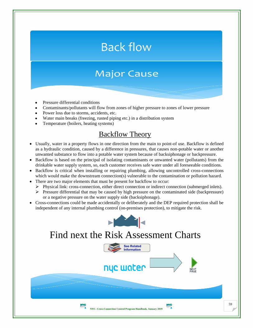
NYC- Cross-Connection Control Program Handbook, January 2019
59
Pressure differential conditions
Contaminants/pollutants will flow from zones of higher pressure to zones of lower pressure
Power loss due to storms, accidents, etc.
Water main breaks (freezing, rusted piping etc.) in a distribution system
Temperature (boilers, heating systems)
Backflow Theory
Usually, water in a property flows in one direction from the main to point-of use. Backflow is defined
as a hydraulic condition, caused by a difference in pressures, that causes non-potable water or another
unwanted substance to flow into a potable water system because of backsiphonage or backpressure.
Backflow is based on the principal of isolating contaminants or unwanted water (pollutants) from the
drinkable water supply system, so, each customer receives safe water under all foreseeable conditions.
Backflow is critical when installing or repairing plumbing, allowing uncontrolled cross-connections
which would make the downstream connection(s) vulnerable to the contamination or pollution hazard.
There are two major elements that must be present for backflow to occur:
Physical link: cross-connection, either direct connection or indirect connection (submerged inlets).
Pressure differential that may be caused by high pressure on the contaminated side (backpressure)
or a negative pressure on the water supply side (backsiphonage).
Cross-connections could be made accidentally or deliberately and the DEP required protection shall be
independent of any internal plumbing control (on-premises protection), to mitigate the risk.
Find next the Risk Assessment Charts
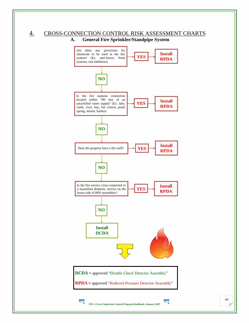
NYC- Cross-Connection Control Program Handbook, January 2019
60
4. CROSS-CONNECTION CONTROL RISK ASSESSMENT CHARTS A. General Fire Sprinkler/Standpipe System
Are there any provisions for
chemicals to be used in the fire system? (Ex. anti-freeze, foam
systems, rust inhibitors)
NO
YES Install
RPDA
Is the fire siamese connection
located within 700 feet of an
uncertified water supply? (Ex. lake, creek, river, bay, fire cistern, pond,
spring, stream, harbor)
YES Install
RPDA
NO
Does the property have a fire well? Install
RPDA
Is the fire service cross-connected to a hazardous domestic service on the
house side of BFP assemblies? YES
Install
RPDA
DCDA = approved “Double Check Detector Assembly”
RPDA = approved “Reduced Pressure Detector Assembly”
Install
DCDA
NO
NO
YES

NYC- Cross-Connection Control Program Handbook, January 2019
61
~ Property ~
Residential Mixed Use
YES NO
Is the property
rated as
aesthetically
objectionable?
Is the nature of occupancy
categorically hazardous? Ex.:
hospitals, medical offices/clinics,
laundry, sewage treatment plants,
mortuaries and most industrial
concerns. (See Typical Significant
Risk of Hazards for more
examples, P. 49)
Request an exemption
as per requirements
Non-Residential
Does the property maintain any
hazardous fixtures? Ex.: bidet,
swimming pool, irrigation
system, cooling tower, large
boiler, coin or card-operated
laundry machines, well? (See
Assessment of Residential
Dwellings for more examples
and details, P. 65)
NO YES
Yes
Install
DCVA Install
RPZA
Install
DCVA
Yes
DCVA = approved “Double Check Valve Assembly”
RPZA = approved “Reduced Pressure Zone Assembly”
Is the property
rated as
non-
hazardous?
Install
RPZA

NYC- Cross-Connection Control Program Handbook, January 2019
62
C. Process of Hazard Assessment
(There is no one single factor that dictates the assessment-making process)
(This presentation provides an approach to perform a property risk assessment and regulatory requirements)
1. 2. 3. 4.
Are local RPZAs installed?
No
Health Hazard?
Applicant (PE/RA) shall review and assess existing/new field to ensure the entailed BFP
assembly is proper and commensurate with the degree of hazard
DEP issues an
official approval
for BFP plans as
determined by
the Department
DEP issues an
official approval
for exemption as
determined by
the Department
Finals
Non-Hazardous with
Hazardous Fixtures,
(Large/chemically
treated boilers, and/or
cooling towers only)?
Aesthetically
Objectionable?
Applicant develops BFP plans
utilizing protocol for the final
verification
DEP issues final
certification(s) with
claims, limitations,
and requirements for
the appropriate use
Install DCVA
Non-Hazardous?
Yes
Applicant develops
an exemption
request as per
DEP requirements
Yes
Rely on local plumbing
control, in accordance
with DOB code, which
is thoroughly surveyed
and assessed
Facility’s Degree of Assessed Health Hazard
Yes
Install RPZA
Yes
Yes
No
No
No
The proper application of a backflow preventer depends on an accurate assessment of
the risk to the potable water supply (CWM) from a customer’s entire plumbing system
NYC- Cross-Connection Control Program Handbook, January 2019
63
Section 5
1. INSTRUCTIONS FOR GETTING A BACKFLOW PREVENTION EXEMPTION
(ONLY for Domestic Water Service line dedicated to Domestic Plumbing Fixtures) http://www.nyc.gov/html/dep/pdf/water_sewer/7_Form_for_BFP_Exemption_Domestic.pdf
1. Each property is unique and requires an evaluation. Any cross-connection protected against backflow at the
time of this program becomes effective may stay and continue with the same protection unless:
The existing protection is deemed inadequate by the customer or determined by the DEP.
DEP officially notifies the customer that a change shall be made.
2. The exemption will expire at any time that the BFP assembly shall be installed. In such cases, the BFP
assembly shall be of the type required by the property’s degree of assessed health hazard. Any alterations,
modifications, or additions (new plumbing fixture/equipment can be added, or tenancy and ownership can
change) that affect the water system (causing health hazard, high or low) shall render the exemption void.
3. The degree of health hazard shall be assessed to determine that the residential building is qualified for an
exemption from the DEP containment BFP requirements based on the hazard-risk assessment. No waive or
exemption can be granted because of architectural style, design, decorations, budgetary constraints or alike.
4. A typed engineering report on PE/RA letter head shall be submitted (solely or included with plans, if any)
following the format of the sample letters (# 3) found on page 71. Two (2) original copies are required:
a. Describe the building and occupancy in detail (# of floors, # of dwelling units, etc.).
b. Provide information pertaining to the general use of water system (either existing or proposed). A water
riser diagram, approved by DOB, for the new development/proposed water system shall be provided.
5. A typed letter on PE/RA letter head following the format of the sample Exemption letter found on P. 66. Do
not omit any of the items. Two (2) original copies (updated form), are required; solely or with the plans.
6. Do site plans (if solely) for the entire property (address, block and lot #s) indicating the domestic water
service (state and size), property line, North arrow, mains, and streets. Two (2) original copies are required.
7. If BFP plans are submitted by a PE/RA, the exemption letter shall be signed by the same PE/RA. In all
cases, exemption letter shall be signed originals by the property owner/customer.
8. Submit TWO (2) ORIGINAL sets (letter sized) of items 4, 5 and 6, along with the required filing fee, to:
NYC-DEP-BWSO- Planning & Permitting
Cross-Connection Control Unit
3rd
Floor Low-Rise
59-17 Junction Blvd.
Flushing, NY 11373
9. Submission of completed paperwork does not guarantee an exemption is granted. Any exemption request,
approved or denied, will be done so in writing and DEP approval or denial letter will be issued to notify both
retained applicant and property owner.
10. If the exemption is denied, the applicant (PE or RA) shall submit two (2) sets of complete plans to install the
appropriate containment backflow prevention assembly(s) in accordance with the Program requirements.
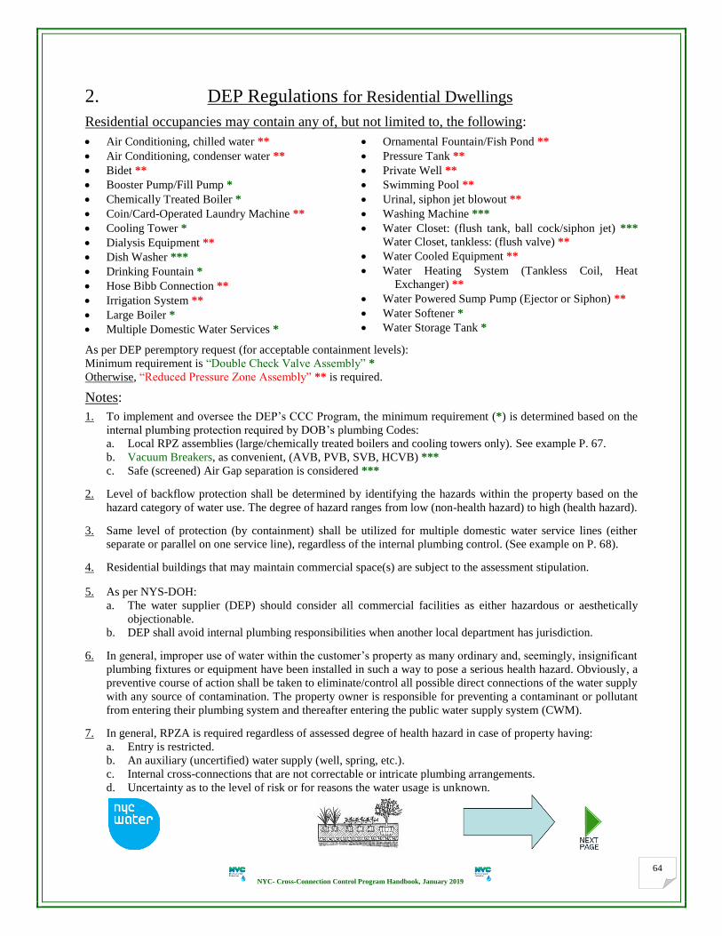
NYC- Cross-Connection Control Program Handbook, January 2019
64
2. DEP Regulations for Residential Dwellings
Residential occupancies may contain any of, but not limited to, the following:
Air Conditioning, chilled water **
Air Conditioning, condenser water **
Bidet **
Booster Pump/Fill Pump *
Chemically Treated Boiler *
Coin/Card-Operated Laundry Machine **
Cooling Tower *
Dialysis Equipment **
Dish Washer ***
Drinking Fountain *
Hose Bibb Connection **
Irrigation System **
Large Boiler *
Multiple Domestic Water Services *
Ornamental Fountain/Fish Pond **
Pressure Tank **
Private Well **
Swimming Pool **
Urinal, siphon jet blowout **
Washing Machine ***
Water Closet: (flush tank, ball cock/siphon jet) ***
Water Closet, tankless: (flush valve) **
Water Cooled Equipment **
Water Heating System (Tankless Coil, Heat
Exchanger) **
Water Powered Sump Pump (Ejector or Siphon) **
Water Softener *
Water Storage Tank *
As per DEP peremptory request (for acceptable containment levels):
Minimum requirement is “Double Check Valve Assembly” *
Otherwise, “Reduced Pressure Zone Assembly” ** is required.
Notes:
1. To implement and oversee the DEP’s CCC Program, the minimum requirement (*) is determined based on the
internal plumbing protection required by DOB’s plumbing Codes:
a. Local RPZ assemblies (large/chemically treated boilers and cooling towers only). See example P. 67.
b. Vacuum Breakers, as convenient, (AVB, PVB, SVB, HCVB) ***
c. Safe (screened) Air Gap separation is considered ***
2. Level of backflow protection shall be determined by identifying the hazards within the property based on the
hazard category of water use. The degree of hazard ranges from low (non-health hazard) to high (health hazard).
3. Same level of protection (by containment) shall be utilized for multiple domestic water service lines (either
separate or parallel on one service line), regardless of the internal plumbing control. (See example on P. 68).
4. Residential buildings that may maintain commercial space(s) are subject to the assessment stipulation.
5. As per NYS-DOH: a. The water supplier (DEP) should consider all commercial facilities as either hazardous or aesthetically
objectionable. b. DEP shall avoid internal plumbing responsibilities when another local department has jurisdiction.
6. In general, improper use of water within the customer’s property as many ordinary and, seemingly, insignificant
plumbing fixtures or equipment have been installed in such a way to pose a serious health hazard. Obviously, a
preventive course of action shall be taken to eliminate/control all possible direct connections of the water supply
with any source of contamination. The property owner is responsible for preventing a contaminant or pollutant
from entering their plumbing system and thereafter entering the public water supply system (CWM).
7. In general, RPZA is required regardless of assessed degree of health hazard in case of property having:
a. Entry is restricted.
b. An auxiliary (uncertified) water supply (well, spring, etc.).
c. Internal cross-connections that are not correctable or intricate plumbing arrangements.
d. Uncertainty as to the level of risk or for reasons the water usage is unknown.

NYC- Cross-Connection Control Program Handbook, January 2019
65
3. Risk Assessment of Residential Dwellings
DEGREE OF HAZARD Requirements for single- and multi-family residences are assessed based on site hazards:
A. A dedicated domestic water service line (either separate or on combined off fire service) for residential dwellings
in conformance with the following are considered being non-hazardous and does not require backflow protection
(containment approach to cross-connection control):
1. No connections to an auxiliary water supply such as a well, cistern, spring and so forth.
2. No booster/fill pumps.
3. No water powered sump pump (ejector or siphon pump).
4. No lawn sprinkler or irrigation systems.
5. No other potential high hazards including, but not limited to: boiler feed corrosion inhibitors, antifreeze
loops, heat exchanger, tankless coil, bidet, dialysis equipment, urinal, irrigation system, and swimming pool.
6. No other potential low hazards including, but not limited to: washing machines, dish washers, ice makers,
tubs, sinks, lavatories, water closets, small gas boilers/water heaters, non-residential sinks, and alike unless
they are mechanically equipped with local plumbing control such as vacuum breakers, air gap separation,
etc. in compliance with DOB plumbing code in effect (in-premises protection). The plumbing shall be
surveyed to determine if the protection provided is satisfactory (rely on Internal Plumbing Control). Surveys
shall be performed to identify actual or potential, controlled and uncontrolled cross-connections.
7. No fire system is fed off the domestic service/system.
8. No commercial uses or agricultural use.
9. No probable future alterations, expansions or extensions in egress, occupancy/activity and/or plumbing
fixtures/equipment that affect the water system are allowed, unless DEP is notified.
10. The property owner shall be made fully aware that if any of the above conditions change, the installation of
appropriate BFP assembly may be required. Cross-connections may be prevalent in the household plumbing
system. [ http://fccchr.usc.edu/_downloads/PCCHP%20Report/PCCHP.Report.pdf ]
[ http://www.nyc.gov/html/dep/pdf/conservation/do-it-yourself-home-water-audit.pdf ]
B. Private Fire protection water services in conformance with the following are considered to be aesthetically
objectionable and require a double check detector assembly (DCDA) to provide cross-connection control by
containment:
1. No chemical provisions added in the fire system.
2. No private fire hydrants.
3. No connections to a secondary water supply such as a well, cistern, etc.
4. No interconnection to a hazardous domestic water service/system.
5. Not within 700 feet of an auxiliary water supply such as a pond, lake, river, creek, etc. where fire siamese
connection(s) (SP and/or SD) is/are located.
C. Combined water services in conformance with the criteria outlined in A and B above are considered to be
aesthetically objectionable and require a double check valve assembly to provide cross-connection control by
containment. A combined water service is one which provides both domestic with fire protection system(s) take
off and shall be protected with RPZA if deemed hazardous (either domestic system and/or fire system). See P.36.
D. All other types of domestic water service connections, either separate or off combined (fire with domestic take
off), that feeds hazardous plumbing fixtures, are considered hazardous and require a reduced pressure zone
assembly (RPZA) to provide cross-connection control by containment.
E. In general, the installation of a BFP assembly on an existing water-based fire suppression service may have a
significant adverse effect on the hydraulic performance of the system. This is relevant when the original design
may not have included a BFP assembly. The applicant shall check the hydraulics of the fire protection system to
ensure the proper operation in conjunction with the presence of the proposed BFP assembly. Same for domestic.

NYC- Cross-Connection Control Program Handbook, January 2019
66
Form for Backflow Prevention Assembly Exemption for a residential building with one Domestic Line only
If the residential building meets ALL conditions that are stated in the sample letter below, TYPE a letter
on PE/RA letterhead giving all information shown on the sample letter. Do not omit any of the points.
NOTE: Where as shown (bracketed italicized items), the appropriate information for related building
shall be provided. Submit to the Cross-Connection Control Unit for approval.
PE / RA L E T T E R H E A D
(Date):
NYC Department of Environmental Protection
Bureau of Water & Sewer Operation
Cross-Connection Control Review Unit
59-17 Junction Blvd. 3rd
Floor Low-rise
Flushing, NY 11373
Re: Containment Backflow Prevention Assembly Exemption in a
Residential Building for a Domestic Water Service Line only
Address: ________________________________________
Block: Lot: County:
Gentlepeople:
Based on the information provided below we respectfully request a review of the (existing building with existing
service, existing building with new service, building being renovated, future building) with regards to containment
backflow prevention requirements.
The referenced location (is/will be) (#) story w/wo (underground levels) (#) residential dwelling units, and (is/will
be) supplied by only one dedicated domestic water service line (or branched off fire service) for domestic plumbing
purposes, which is (size) inch. (Describe in brief the general use of water system ………).
The referenced residential building does NOT contain any of the following:
Air Conditioning, chilled water
Air Conditioning, condenser water
Bidet/Dialysis Equipment
Booster Pump/Fill Pump
Chemically Treated Boiler
Coin/Card-Operated Laundry Machine
Commercial Use
Cooling Tower
Drinking Fountain
Fire protection system (off/fed by - the domestic)
Fish Pond/Ornamental Fountain
Irrigation System/Hose Bibb Connection
Large Boiler (≥ 350,000 BTU)
Multiple Domestic Water Service Lines
Pressure Tank
Private Well/Water Re-use
Swimming Pool
Urinal, siphon jet blowout
Water Cooled Equipment/Water Softener
Water Heating System (Tankless Coil, Heat Exchanger)
Water Powered Sump Pump (Ejector or Siphon)
Water Storage Tank
Based on this information and a detailed and thorough inspection/assessment of the (existing/new building), we
believe this building is rated as non-hazardous and is qualified for exemption from containment backflow prevention
requirements. We are fully aware that if any of the above conditions change, the installation of an appropriate
backflow prevention assembly may be mandatory.
______________________ ____________________
Property Owner's Name PE/RA Name:
Property Owner’s Mailing Address License Number: (if not on letterhead)
Owner's Phone Number Phone Number: (if not on letterhead)
Owner's Signature NYS PE/RA Stamp & Signature

NYC- Cross-Connection Control Program Handbook, January 2019
67
Example (annex to DEP Regulations for premises isolation, P. 58) (Explanation of “Non-hazardous with hazardous fixtures”, only as shown)
1. Hazardous (as no local protection provided)
2. Non-Hazardous with hazardous fixtures
(as local protection provided)
3. Acceptable if proposed

NYC- Cross-Connection Control Program Handbook, January 2019
68
Example for multiple water service lines, either separate or parallel
(Meter) (RPZA) (Meter) (RPZA)
Separate (Tandem)
(Meter) (RPZAs) (MICVs) (Meters) (RPZAs)
Parallel Notes:
For parallel installations (potential for two or more water lines), the total capacity of the BFP assemblies shall
equal or exceed that required by the system. The piping system should be sized hydraulically, taking into account
both volume requirements and pressure loss through the assemblies. Each assembly shall operate normally. Two
units in parallel should result in essentially the same head loss as using a single larger unit. When parallel or bypass installation of BFP assemblies is necessary, both lines shall be equipped with similar
types of assemblies as degree of health hazard shall dictate, followed by T.T. & MOCV on each line separately.
If one connection on the parallel configuration may be removed, tee shall be removed entirely and hard pipe.
A prior written approval from BCS shall be provided along with the BFP plans when proposing the installation
of parallel water meter settings on one water service line or converting parallel installation to one line and also
when proposing multiple water services of similar purpose to the same property, regardless of what they feed.
Unacceptable BFP device/assembly which is used as external containment shall be removed completely and
replaced with an approved assembly. After a BFP assembly is selected, it shall continue to work as designed.
_____________________________________________________
ANNOTATION A backflow preventer is an assembly, device or method that prohibits the reversal of flow of liquids into the potable
water supply system. The term “device” has somewhat found its way into common current vernacular to mean a
backflow preventer that does not have shut-off valves and test cocks as intgeral components. The terms “assembly”
and “device” have been used interchangeably to mean the same product. However, there is an immense difference
between the two categories of mechanical BFP Devices and BFP Assemblies:
BFP Devices: are not to be substituted for applications that require backflow assemblies. They usually do not
include test cocks or shut-off valves, and they are not always designed for field (in-line) testing or repair. They do
not provide the same level of performance that BFP assemblies provide. These devices are used for internal (on
premises) protection and usually come only in smaller sizes. The application of these devices usually comes under
the jurisdiction of the DOB plumbing code, because they usually are located only in private plumbing systems.
BFP Assemblies: are required to have certain parts, such as test cocks and shut-off valves (as integral parts of an
approved assembly). Assemblies are designed for field (in-line) performance testable and repairable. They are used
for containment to prohibit the backflow of non-potable water into the potable water supply system. They shall meet
an approval standard for performance and design.
Standards differ for types of BFP devices and assemblies. Various standards describe different performance
requirements based on the level of protection required.
_____________________________________________________

NYC- Cross-Connection Control Program Handbook, January 2019
69
Section 6
SAMPLE ENGINEERING REPORTS
Introduction:
There are three (3) distinct types of approved mechanical assemblies which are considered to be backflow
prevention assemblies. Nevertheless, it shall be stressed that these are not all equally acceptable as protection against
all types of actual or potential hazards. Properties, having internal cross-connection that are not correctable or
intricate plumbing arrangements which make it impractical to ascertain whether or not cross-connection exist,
require a protection by containment. The degree of health hazard shall be assessed and determined along with the
type of cross-connection present to ascertain which type of BFP assembly is the most suitable to the situation. The
type and use of water service/system plays a decisive role in determining the degree of health hazard on the site.
An elaborated engineering report shall be submitted as part of the BFP plans/exemption submittal.
The report (on the PE/RA’s letter head, formatted on 8.5 x 11” sheets) shall describe the project in detail (entire lot).
Note: If plans were previously approved, a statement shall be clarified to explain why a re-approval is needed.
Items that should be described in the report include, but are not limited to the following:
Building/property description: state, number of floors within the building, type of business, activity, and
occupancy (residential, commercial, medical, industrial, mixed use, etc.) either existing or new. Commercial
spaces/activity/business shall be specified and identified. Any commercial establishment not delineated or non-
residential structure in which the specific business activity cannot be ascertained shall be required to install a
RPZ assembly. Adjacent lot(s) related information, if any, shall be specified and design shall be filed separately.
General use of consumer’s water supply system within the property.
The need of dual BFP assembly is required. Does the property need continuous water supply?
As per the Risk Assessment Chart: description of the characteristics of the firefighting water system(s).
Size and description of all water services, fire (SP and/or SD), domestic or combined (either existing or new).
Description of the proposed installation of the backflow prevention assembly(s): indicate the location of BFP
assembly, drainage, lighting, heating, access to unit, alarm plans (if any), square footage of the floor level
(below grade) where the BFP assembly (if RPZA/RPDA) is to be located.
The elevation and location of the 100-year flood plain in relation to the property. A RPZ/RPD assembly (relief
vent) shall generally be installed one (1) foot above the 100-year flood plain elevation.
An inventory of any existing containment BFP assemblies includes the make, model # (in full), size and serial
number of the assembly. The degree of health hazard for these services shall be thoroughly assessed to ensure
that the planned assembly provides the appropriate level of protection.
Actual or estimated maximum flow demand. Pressure booster/fill pump(s) systems, if any.
Pressures: existing and after the installation of the containment BFP assembly.
Any other useful proof and all pertinent information (updated) to disclose certain issue(s) (i.e. water riser
diagram approved by DOB, clarified pictures/illustrations, etc. to suffice the requirements).
Notes: Project address, block and lot #s shall be specified on all sheets (if any) of the report. Applicant shall avoid
stamp, signature or images over drawings, text reports or any noted information. No lack of ink prints.
The following samples are to be used as references only

NYC- Cross-Connection Control Program Handbook, January 2019
70
……………...….…. PE / RA
……………………. Street, NY, NY 10003
Tel: ( ) …………. E-mail: …………….
USAGE / ACTIVITY-VERIFICATION LETTER
To NYC-DEP-BWSO Date: / / 20_ _
Planning & Permitting
Cross-Connection Control Unit
3rd
Floor Low-Rise
59-17 Junction Blvd.
Flushing, NY 11373
Re Building / Facility Usage Verification
Premises Address: ……………… Street,
Brooklyn, NY 11219
Block: 999443 Lot: 125 County: Kings
① Dear Plan Reviewer,
The information provided below is to verify the usage of the new building with regards to containment backflow
prevention requirements.
The referenced location is a new two (2) story and cellar, two (2) family residences with no commercial uses, no
swimming pool, bidets, irrigation systems, no suction tanks, chemically treated boilers or cooling towers/chillers,
and no coin/card-operated washing machines. The building’s plumbing system is thoroughly assessed to determine
if the protection provided will be satisfactory. All internal cross-connections to all domestic plumbing fixtures will
be mechanically equipped with local plumbing control in compliance with DOB code. Existing water service will be
destroyed and abandoned at the main pursuant to DEP local code.
The new 2” fire sprinkler system is characterized as follows:
1. No chemical provisions used in the fire line (e.g. antifreeze, rust inhibitors).
2. Fire Siamese connection is located more than 700 Ft. of an uncertified source of water.
3. Domestic and fire water risers do not interconnect at any point on the house side of the BFP assembly.
4. No fire wells in the premises.
We are proposing a new 2” combined water service, (domestic service with a fire sprinkler take off).
Based on this information and a detailed thorough inspection of the referenced building and plans, we believe the
domestic usage for the building is aesthetically objectionable and requires a double check valve on the combined
service as shown on the plans as it will not be a source of contamination on NYC-DEP water system. We propose to
install a 2” double check valve, Watts LF007M1QT as required by the NYC-DEP & NYS-DOH. I have made the
property owner/customer fully aware that if any of the above conditions change, the installation of appropriate
backflow prevention assembly may be required.
(Signed PE/RA Stamp)
② Dear Plan Reviewer,
The information provided below is to verify the usage of the existing building with regards to containment
backflow prevention requirements.
The referenced location is an existing three (3) story and cellar, (number) family residence with no commercial
uses, no swimming pool, bidets, irrigation systems, no suction tanks, chemically treated boilers or cooling
towers/chillers, and no coin/card-operated washing machines.
The new 2” fire sprinkler system is characterized as follows:
1. No chemical provisions used in the fire line (e.g. antifreeze, rust inhibitors).
2. Fire Siamese connection is located more than 700 Ft. of an uncertified source of water.
3. Domestic and fire water risers do not interconnect at any point on the house side of the BFP assembly.
4. No fire wells in the premises.
NYC- Cross-Connection Control Program Handbook, January 2019
71
We are proposing a new 2” combined water service, (domestic service with a sprinkler take off).
Based on this information and a detailed thorough inspection of the referenced building and plans, we believe the
domestic usage for the building is aesthetically objectionable. This degree of hazard requires a double check valve
(DCV) on the combined water service. However, considering future expansion, there may be a likelihood that the
degree of hazard becomes Hazardous. Therefore, we propose to install a 2” RPZA, Wilkins 975XL2 as shown on the
plans as required by the NYC-DEP & NYS-DOH. I have made the property owner/customer fully aware that if any
of the above conditions change, the installation of appropriate backflow prevention assembly may be required.
③ (for existing residential buildings) Dear Plan Reviewer,
The information provided below is to verify the usage of the existing building with regards to containment
backflow prevention requirements.
The referenced location is an existing three (3) story and cellar, (twelve) family residence with no commercial
uses, no swimming pool, bidets, irrigation systems, no suction tanks, chemically treated boilers or cooling
towers/chillers, and no coin/card-operated washing machines. The existing domestic water system routes within the
building and is thoroughly surveyed and assessed to determine if the protection provided are satisfactory. All
internal cross-connections to all domestic plumbing fixtures are mechanically equipped with local plumbing control
in compliance with DOB code.
The existing 3” fire sprinkler system is characterized as follows:
1. No chemical provisions used in the fire line (e.g. antifreeze, rust inhibitors).
2. Fire Siamese connection is located more than 700 Ft. of an uncertified source of water.
3. Domestic and fire water risers do not interconnect at any point on the house side of the BFP assembly.
4. No fire wells in the premises.
There is an existing 3” combined water service, (fire sprinkler with 2” domestic service take off).
Based on this information and a detailed thorough inspection of the referenced building and plans, we believe the
domestic usage for the building is non-hazardous and qualified for exemption from containment BFP requirements
as it will not be a source of contamination on NYC-DEP water system as per attached letter. We propose to install a
3” double check detector assembly, Watts 757 with by-pass meter as required by the NYC-DEP & NYS-DOH. I
have made the property owner/customer fully aware that if any of the above conditions change, the installation of
appropriate backflow prevention assembly may be required.
Annex to ③ (for new residential buildings):
The referenced location is a new two (2) story and cellar building, (Single) family residence with no commercial
uses, no swimming pool, bidets, irrigation systems, no suction tanks, chemically treated boilers or cooling
towers/chillers, and no coin/card-operated washing machines. The new domestic water system routes within the
building (as per attached water riser diagram, approved by DOB). The building’s plumbing system is thoroughly
assessed to determine if the protection provided will be satisfactory. All internal cross-connections to all domestic
plumbing fixtures will be mechanically equipped with local plumbing control in compliance with DOB code.
④ Dear Plan Reviewer,
The information provided below is to verify the usage of the new building with regards to containment backflow
prevention requirements.
The referenced location is a new nine (9) story with basement and cellar, mixed use building for (48) residential
apartments with health care/ambulatory facility and restaurant on 1st floor. There are 3 coin-operated laundry
machines in the cellar. At time of survey, there was evidence that the area of the new building has been affected
from tropical storm “Sandy”. So, proposed “RPZ” assembly is located on the First Floor, above Grade Level.
The new 6” combination fire sprinkler/standpipe system is characterized as follows:
1. No chemical provisions used in the fire line (e.g. antifreeze, rust inhibitors).
2. Fire Siamese connection is located more than 700 Ft. of an uncertified source of water.
3. Domestic and fire water risers do not interconnect at any point on the house side of the BFP assemblies.
4. No fire wells in the premises.
We are proposing a new 4” domestic water service and 6” combination fire sprinkler/standpipe service.
Based on this information and a detailed thorough inspection of the referenced building and plans, we believe the
domestic usage for the building is hazardous and requires a RPZ assembly on the domestic as shown on the plans.
We propose to install a 4” RPZA Wilkins 375A and 6” double check detector assembly Wilkins 350ADA with by-
pass meter, as required by the NYC-DEP & NYS-DOH. I have made the property owner/customer fully aware that
if any of the above conditions change, the installation of appropriate backflow prevention assembly may be required.

NYC- Cross-Connection Control Program Handbook, January 2019
72
⑤ Dear Plan Reviewer,
The information provided below is to verify the usage of the new building with regards to containment backflow
prevention requirements.
The referenced location is a new seven (7) story with basement and cellar, mixed use building for (48) residential
apartments with community facility and restaurant on 1st floor. There are 3 coin-operated laundry machines in the
cellar. At time of survey, there was no evidence of any damage to the area of the new building from tropical storm
“Sandy”. The area is fully functional with all services and mechanical intact. So, proposed BFP assemblies are
located on the Cellar Floor, below Grade Level.
The new 4” combination fire sprinkler/standpipe system is characterized as follows:
1. No chemical provisions used in the fire line (e.g. antifreeze, rust inhibitors).
2. Fire Siamese connection is located more than 700 Ft. of an uncertified source of water.
3. Domestic and fire water risers do not interconnect at any point on the house side of the BFP assemblies.
4. No fire wells in the premises.
We are proposing a new 4” domestic water service and 6” combination fire sprinkler/standpipe service.
Based on this information and a detailed thorough inspection of the referenced building and plans, we believe the
domestic usage for the building is hazardous and requires a RPZ assembly on the domestic as shown on the plans.
We propose to install a 4” RPZA Watts 957 and 6” double detector check assembly Watts LF757 with by-pass
meter, as required by the NYC-DEP & NYS-DOH. I have made the property owner/customer fully aware that if any
of the above conditions change, the installation of appropriate backflow prevention assembly may be required.
⑥ Dear Plan Reviewer,
The information provided below is to verify the usage of the existing building with regards to containment
backflow prevention requirements.
The referenced location is an existing twenty-nine (29) story with basement and cellar, mixed use building for
(148) residential apartments with community facility and restaurant on 1st floor. There are 12 coin-operated laundry
machines in the cellar. The building maintains large boiler, cooling towers and chillers.
The existing domestic and fire (sprinkler/standpipe) water, supplied directly to all fixtures, is fed by the existing roof
tanks. The roof tanks are filled by the existing house fill pumps with approved (safe) air gaps. There are no water
connections to any fixtures in the building after the meter outlet control valve to the fill pumps as illustrated on the
attached water riser diagram approved by DOB.
There is an existing 6” combined water service to remain for the entire building.
Based on this information and a detailed thorough inspection of the referenced building and plans, we believe the
domestic usage for the building is aesthetically objectionable. This degree of hazard requires a double check valve
assembly on the combined water service as required by the NYC-DEP & NYS-DOH. I have made the property
owner/customer fully aware that if any of the above conditions change, the installation of appropriate backflow
prevention assembly may be required.
⑦ Dear Plan Reviewer,
The information provided below is to verify the usage of the existing park with regards to containment backflow
prevention requirements.
The referenced location is a park used as a recreational area for the public.
The park maintains one building as comfort station. It is not subject to flooding.
The park will be supplied with one new 3” domestic water service.
The Park has no fire protection system.
The use of the proposed 3” domestic water service will be for supplying water to:
• 2 non-freeze ground hydrants for irrigation system.
• 3 non-freeze drinking fountains.
• 6 pieces of spray equipment and toilet room fixtures within the comfort station.
As per the hydrant flow test performed by NYC-DEP taken on -------- Avenue:
• The static pressure was 45PSI.
• The residual pressure was 42PSI @ 500 Gal.
The water service shall be shut down and winterized during cold weather.
Based on this information and a detailed thorough inspection of the referenced location and plans, we believe the
domestic usage for the park is hazardous and requires a RPZ assembly on the domestic water service as shown on
the plans. We propose to install a 3” RPZA Wilkins 375A, located on 1st floor, as required by the NYC-DEP &

NYC- Cross-Connection Control Program Handbook, January 2019
73
NYS-DOH. The water meter rig will be located in the basement floor of the comfort station. I have made the
property owner/customer fully aware that if any of the above conditions change, the installation of appropriate
backflow prevention assembly may be required.
⑧ Dear Plan Reviewer,
The information provided below is to verify the usage of the existing park with regards to containment backflow
prevention requirements.
The referenced location is a park used as a recreational area for the public.
The park will be supplied with one new 2” domestic water service.
The Park has no fire protection system. It is not subject to flooding.
The use of the proposed 2” domestic water service will be for supplying water to:
• 2 non-freeze ground hydrants for irrigation system
• 3 non-freeze drinking fountains
As per the hydrant flow test performed by NYC-DEP taken on -------- Avenue:
• The static pressure was 45PSI.
• The residual pressure was 42PSI @ 500 Gal.
The water service shall be shut down and winterized during cold weather.
Based on this information and a detailed thorough inspection of the referenced location and plans, we believe the
domestic usage for the park is hazardous and requires a RPZ assembly on the domestic water service. We propose to
install a 2” RPZA Febco LF825YA and 1.5” DCV assembly Febco LF850 on the branch line to drinking fountains,
as required by the NYC-DEP & NYS-DOH. The water meter rig, DCV and RPZ assemblies will be located in a
standard pre-cast concrete structure as shown on the plans. I have made the property owner/customer fully aware
that if any of the above conditions change, the installation of appropriate backflow prevention assembly may be
required.
⑨ Re: Withdrawal Letter (for Approval or Submittal)
Premises: Address: ……………… Street,
Brooklyn, NY 11219
Block: 999443 Lot: 125 County: Kings
Dear Plan Reviewer,
Please be advised that we wish to withdraw the latest filing for backflow prevention assembly plans
approval/submittal which was received by NYC-DEP-CCCU on 00/00/0000.
We will reinstate and utilize the previous approval which was approved on 00/00/0000, approval # 00000000.
Reason for the withdrawal of submittal --------
Truly,
…………………………….……., PE/RA
………………… Street, Suite 102
New York, NY 10003
⑩ Re: Supersede Letter
Premises: Address: ……………… Street,
Brooklyn, NY 11219
Block: 999443 Lot: 125 County: Kings
Dear Plan reviewer,
ABCDEFG Holding, LLC is the property owner of the captioned address above.
We are requesting now that any previous approved/submitted plans by different Applicant to be nullified and
voided. A new Backflow Prevention Assembly Application and Plans is hereby submitted by ---------, PE/RA,
and is requested for Approval.
Sincerely,
Owner’s Name:
Address:
Tel: Notary Public _______________________________________________________________________________________

NYC- Cross-Connection Control Program Handbook, January 2019
74
Section 7
NOMENCLATURE (LEGEND) To remain concise and enhance readability, the following abbreviations are used throughout these standards Acronym/Abbreviation Description ACV
A.F.F.
A.G. AGF
BCS
BFP/BFPA Bldg.
BF, BFG, BG Valve
BV BWV
CIP
CL CLR
Comb.
C.V. CW
CWM
DCVA DCDA
DIP
DN Dom.
Ex.
F F.D.
F.F.
F.A.I. GPM
GV
HB HCV
IWM
Max. Min.
MICV
MOCV NRS Valve
NTS
NYC OSHA
OS&Y Valve
PG PIV
PLBG
POE PRV
PSI
PWM
PWS
RPDA
RPZA S. #
SOV (SP) / (SD)
Svc.
TS TYP.
T.T.
USSV/DSSV WM
3X
5X
Automatic Control Valve (Flood Protection Shutdown Valve)
Above Finished Floor Air Gap Separation
Air Gap Fitting
Bureau of Customer Services Backflow Prevention Assembly
Building
Butterfly Gate Valve Ball Valve
Back Water (Check) Valve
Cast Iron Pipe Center Line
Clearance
Combined Curb Valve
Cold Water Piping
City Water Main Double Check Valve Assembly
Double Check Detector Assembly
Ductile Iron Pipe Down
Domestic
Example // Existing Flow Direction
Floor Drain
Finished Floor Fresh Air Intake
Gallon per minute
Gate Valve (F x F, F x G, G x F, G x G) [F: Flange, G: Groove]
Hot Box
House Control Valve
Internal Water Main Maximum
Minimum
Meter Inlet Control Valve Meter Outlet Control Valve
Non-Rising Stem Valve
Not to Scale New York City
Occupational Safety & Health Administration
Outside Stem & Yoke Valve Pressure Gauge
Post Indicator Valve
Plumbing Point of Entry (Point of Service), (Point of Use)
Pressure Reducing Valve
Pound per square inch Private Water Main
Public Water System
Reduced Pressure Detector Assembly Reduced Pressure Zone Assembly
Serial # Shut-Off Valve
Sprinkler Service / Standpipe Service (Fire)
Service Tamper Switch (Supervisory Switch)
Typical
Test Tee (Water Meter Test Tee Assemblage) Upstream Shot-off Valve/Downstream Shut-off Valve
Water Meter
3 Times of the Diameter of the Pipe 5 Times of the Diameter of the Pipe

NYC- Cross-Connection Control Program Handbook, January 2019
75
Section 8
EXAMPLES N O T E S
Backflow preventers are part of a property owner/customer's private plumbing system(s). All
containment BFP assemblies shall be installed in accordance with the Program requirements. Proper
installation of the BFP assembly plays a decisive role in protecting the public water supply system by
helping to ensure the assembly performs as it is intended while providing proper and safe access for
testing, maintenance and repair. Once the hazard assessment for a water user is completed, the
appropriate type of backflow protection shall be established. BFP assembly shall be ordered with
valves attached to the assembly by the manufacturer (upstream and downstream of the assembly).
This insert serves as a guidance document for the proper installation of BFP assemblies. This sample
drawings/set-ups is solely intended to supply as much information as possible of the diverse options
available for BFP assemblies’ installations. They are GENERIC PRINTS only. The information
contained herein is not intended to represent the full installation information. So, applicant is required
to thoroughly read all installation criteria before creating the design of BFP plans. (See P. 38).
Specified dimensions/clearances shall take precedence over scaled dimensions.
One drawing is worth 1000 words. Drawing is the Engineering Language.
All referenced examples are subject to change by DEP as related to any proposed project.
Any depicted example does not intentionally represent or promote any manufacturer, specific BFP
assembly, or any other device.
All drawings shall include the name (if any), address, block and lot #s of the property, be stamped and
signed by the applicant (PE/RA). Applicant shall avoid stamp and signature over drawings or any
noted information, keeping adequate space on plans for DEP approval stamps on all submitted sheets.
Safe, Abundant Drinking Water

NYC- Cross-Connection Control Program Handbook, January 2019
76
SAMPLE S I T E P L A N
(all occupancies in the property shall be specified)
INDICATE THE FOLLOWING ON SITE PLAN: (is not an exhhaustive list)
1. Location, state and type of water main
2. Location of curb line, property line
3. Street name
4. Cross street name(s)
5. Distance from closest Cross Street
6. North Arrow
7. Location, state, type and size of water service(s), [all water services on one plot plan]
Note: A dedicated tap/wet connection and water service shall be installed for each
substantive building in the same lot, regardless of the ownership. No Grandfather
8. Removal/capping of existing water service(s)
9. Location of water meter
10. Location of proposed or existing to remain (legalization) BFP assembly
11. Building lay out (footprint); multiple buildings, stores and locations with house #s, if any
12. Key Map, if any
13. Property address, block # and lot # (tentative lot, if any); [lot by lot basis]
14. See Plot Plan (Site Plan) (P. 40) for more requirements, if any
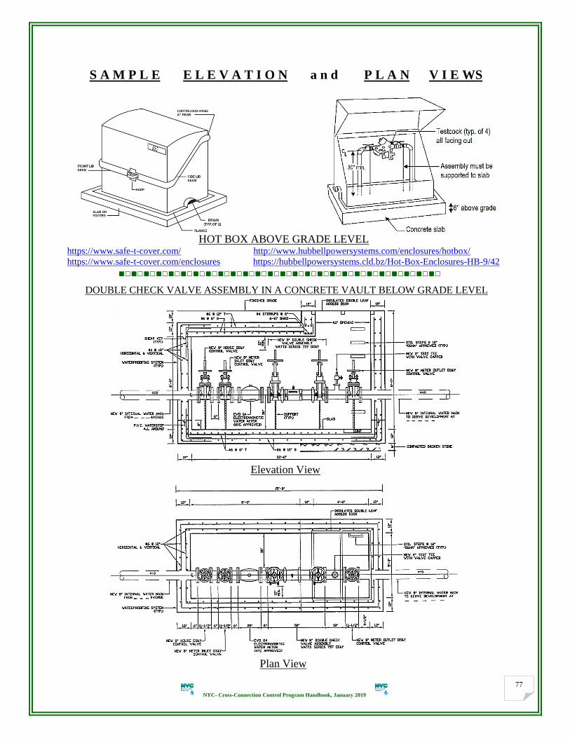
NYC- Cross-Connection Control Program Handbook, January 2019
77
S A M P L E E L E V A T I O N a n d P L A N V I E WS
HOT BOX ABOVE GRADE LEVEL https://www.safe-t-cover.com/ http://www.hubbellpowersystems.com/enclosures/hotbox/
https://www.safe-t-cover.com/enclosures https://hubbellpowersystems.cld.bz/Hot-Box-Enclosures-HB-9/42
■□■□■□■□■□■□■□■□■□■□■□■□■□■□■□■□■□■□■□■□■□■□■□■□■□■□
DOUBLE CHECK VALVE ASSEMBLY IN A CONCRETE VAULT BELOW GRADE LEVEL
Elevation View
Plan View

NYC- Cross-Connection Control Program Handbook, January 2019
78
TYPICAL INSTALLATION FOR: DCDA IN A CONCRETE VAULT
(Vaults shall be large enough to bodily enter)
(Refer to: BCS Typical Meter Vault, RCNY Title 15, Chapter 20)
■□■□■□■□■□■□■□■□■□■□■□■□■□■□■□■□■□■□■□■□■□■□■□■□■□■□
Note: Compact BFP assemblies with BFG/BF/BG-option can be utilized to maintain less space and
minimize the cost.
■□■□■□■□■□■□■□■□■□■□■□■□■□■□■□■□■□■□■□■□■□■□■□■□■□■□
TYPICAL INSTALLATION FOR: Underground vault, extended with the cellar floor under the sidewalk
■□■□■□■□■□■□■□■□■□■□■□■□■□■□■□■□■□■□■□■□■□■□■□■□■□■□

NYC- Cross-Connection Control Program Handbook, January 2019
79

NYC- Cross-Connection Control Program Handbook, January 2019
80
Typical Installation
For: COMBINED WATER SERVICE, FIRE WITH DOMESTIC TAKE OFF
(IN BUILDING WITH NO BASEMENT OR CELLAR)
(NTC)
■□■□■□■□■□■□■□■□■□■□■□■□■□■□■□■□■□■□■□■□■□■□■□■□■□■□
AG on tank or reservoir Drainage details for RPDA

NYC- Cross-Connection Control Program Handbook, January 2019
81
Drainage details where there is a house sewer connection high above floor slab
Elevation Views ■□■□■□■□■□■□■□■□■□■□■□■□■□■□■□■□■□■□■□■□■□■□■□■□■□■□
TYPICAL INSTALLATION FOR: COMBINED WATER SERVICE, DOMESTIC WITH FIRE TAKE OFF
(NTS)
Note: Control shut-off valve (in compliance with DOB code) shall be installed in the downstream of the MOCV.
■□■□■□■□■□■□■□■□■□■□■□■□■□■□■□■□■□■□■□■□■□■□■□■□■□■□
FIRE SP SERVICE (DCDA in vertical)
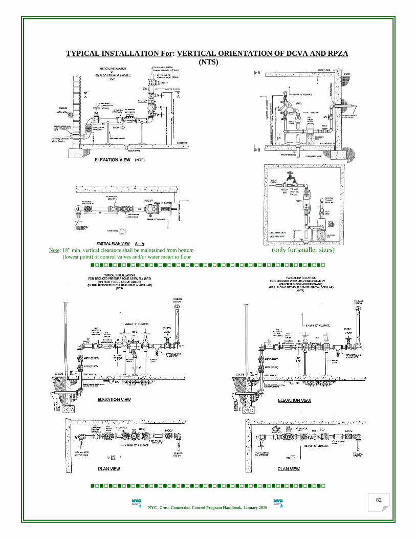
NYC- Cross-Connection Control Program Handbook, January 2019
82
TYPICAL INSTALLATION For: VERTICAL ORIENTATION OF DCVA AND RPZA
(NTS)
Note: 18” min. vertical clearance shall be maintained from bottom (only for smaller sizes) (lowest point) of control valves and/or water meter to floor
■□■□■□■□■□■□■□■□■□■□■□■□■□■□■□■□■□■□■□■□■□■□■□■□■□■□
■□■□■□■□■□■□■□■□■□■□■□■□■□■□■□■□■□■□■□■□■□■□■□■□■□■□
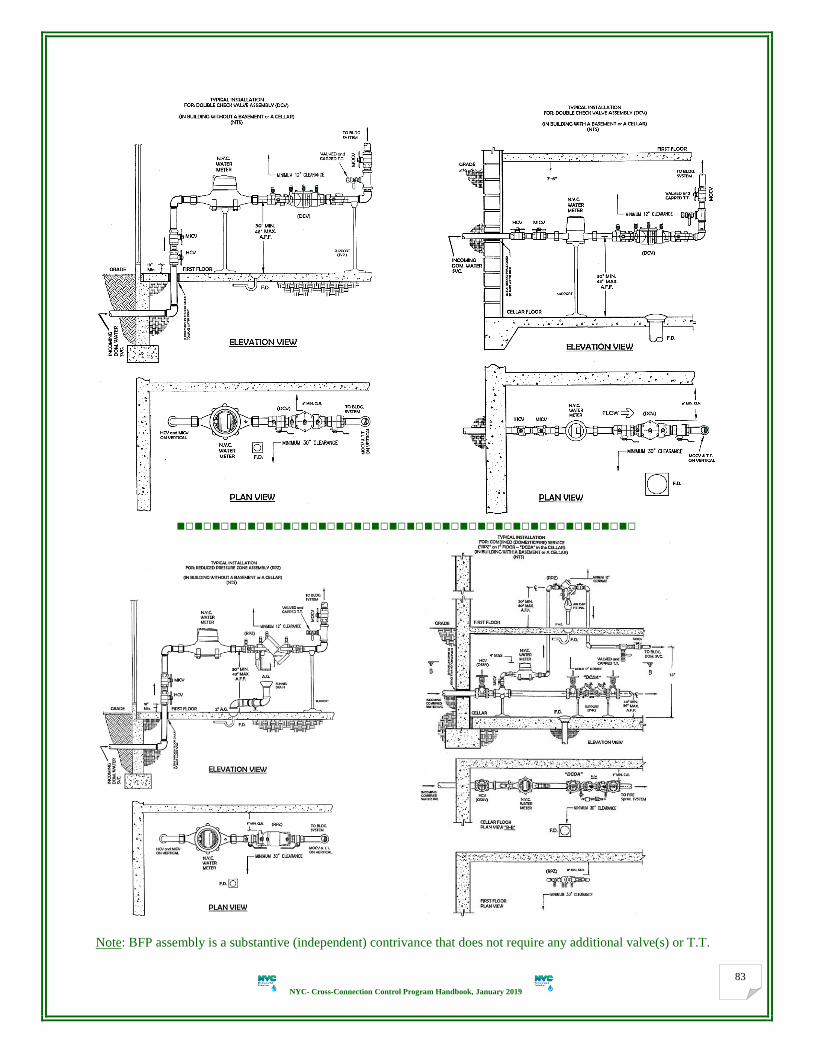
NYC- Cross-Connection Control Program Handbook, January 2019
83
■□■□■□■□■□■□■□■□■□■□■□■□■□■□■□■□■□■□■□■□■□■□■□■□■□■□
Note: BFP assembly is a substantive (independent) contrivance that does not require any additional valve(s) or T.T.

NYC- Cross-Connection Control Program Handbook, January 2019
84
■□■□■□■□■□■□■□■□■□■□■□■□■□■□■□■□■□■□■□■□■□■□■□■□■□■□
Use of fire hydrant (subject to approval by BCS), See P. 29, item # 5
■□■□■□■□■□■□■□■□■□■□■□■□■□■□■□■□■□■□■□■□■□■□■□■□■□■□
Monitor Switch (MS) system is approved by USC-FCCCHR and shall be utilized according to the manufacturer's
strict instructions and DOB code as well. Safety precautions shall be highly utilized so that no part of the whole
control system can be submerged. ACV (for flood control), controlled by a Flow Switch (FS), Sensor, EST, MS, etc.
may be required upon the Engineer’s request and/or the property owner’s discretion and responsibility in anyway.
Note: ACV shall not be installed in the upstream water connection that feeds any fire system, prior to BFP assembly.
Sample Flood Protection Shutdown Valve controlled by Flow Switch (FS) or (MS/EST)
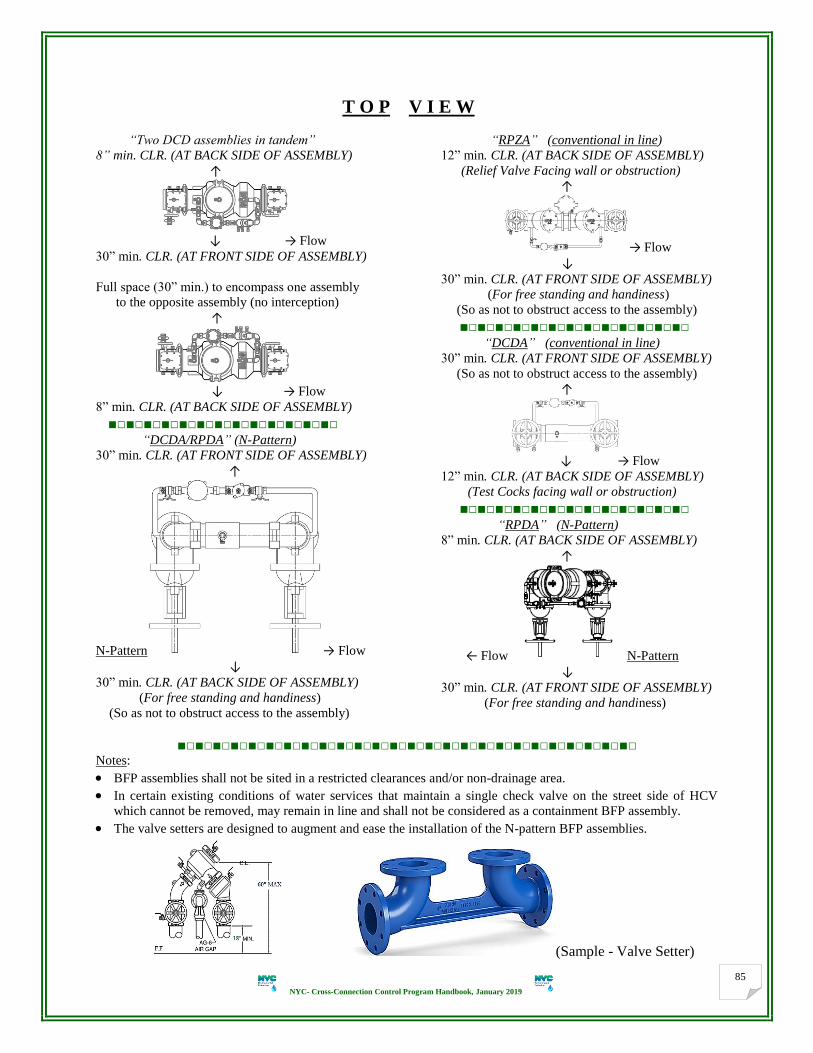
NYC- Cross-Connection Control Program Handbook, January 2019
85
T O P V I E W
“Two DCD assemblies in tandem”
8” min. CLR. (AT BACK SIDE OF ASSEMBLY)
↑
↓ → Flow 30” min. CLR. (AT FRONT SIDE OF ASSEMBLY)
Full space (30” min.) to encompass one assembly
to the opposite assembly (no interception)
↑
↓ → Flow 8” min. CLR. (AT BACK SIDE OF ASSEMBLY)
■□■□■□■□■□■□■□■□■□■□■□■□■□ “DCDA/RPDA” (N-Pattern)
30” min. CLR. (AT FRONT SIDE OF ASSEMBLY)
↑
N-Pattern → Flow
↓ 30” min. CLR. (AT BACK SIDE OF ASSEMBLY)
(For free standing and handiness)
(So as not to obstruct access to the assembly)
“RPZA” (conventional in line)
12” min. CLR. (AT BACK SIDE OF ASSEMBLY)
(Relief Valve Facing wall or obstruction)
↑
→ Flow ↓ 30” min. CLR. (AT FRONT SIDE OF ASSEMBLY)
(For free standing and handiness)
(So as not to obstruct access to the assembly)
■□■□■□■□■□■□■□■□■□■□■□■□■□ “DCDA” (conventional in line) 30” min. CLR. (AT FRONT SIDE OF ASSEMBLY)
(So as not to obstruct access to the assembly) ↑
↓ → Flow 12” min. CLR. (AT BACK SIDE OF ASSEMBLY)
(Test Cocks facing wall or obstruction)
■□■□■□■□■□■□■□■□■□■□■□■□■□ “RPDA” (N-Pattern)
8” min. CLR. (AT BACK SIDE OF ASSEMBLY)
↑
← Flow N-Pattern
↓ 30” min. CLR. (AT FRONT SIDE OF ASSEMBLY)
(For free standing and handiness)
■□■□■□■□■□■□■□■□■□■□■□■□■□■□■□■□■□■□■□■□■□■□■□■□■□■□ Notes:
BFP assemblies shall not be sited in a restricted clearances and/or non-drainage area.
In certain existing conditions of water services that maintain a single check valve on the street side of HCV
which cannot be removed, may remain in line and shall not be considered as a containment BFP assembly.
The valve setters are designed to augment and ease the installation of the N-pattern BFP assemblies.
(Sample - Valve Setter)

NYC- Cross-Connection Control Program Handbook, January 2019
86
INDICATE THE FOLLOWING FACTS ON ELEVATION AND PLAN VIEWS:
1. All incoming water service lines shall be protected (with approved assemblies), specified and shown. Water
services can be extended only from water main (CWM, IWM or PWM). No water service from water service.
2. Same level of protection shall be utilized for all similar types of water service lines (existing or new).
3. Water service lines shall not be interconnected at any point upstream of BFP assemblies.
4. All items (fixtures) on the drawing shall be labeled and specified conspicuously. Direction of flow shall be
denoted on all views and actual location (floor) of meter and BFP assembly and grade level with dimensions.
5. Same type of water service connections cannot be extended from same source of water main.
6. Approved setting up and piping materials shall be utilized. Existing water service shall not be enlarged at the
point of service, once the piping is exposed in the property, except downstream of the meter for BFP assembly
or the MOCV, or the BFP assembly on the fire service line; if required, and subject to approval by DOB. The
size of the meter shall not exceed the size of the water service (in compliance with BCS requirements).
7. Existing piping, installations, configuration, etc. shall be modified as required to provide an approved system.
8. Existing fixtures shall remain as is as deemed acceptable, approved and readily accessible.
9. Size of the entailed DCVA/RPZA (USC approved) shall be of the same size as the master water meter or
larger. Sudden enlargement is not hydraulically recommended to avoid the head loss due to the turbulent flow.
10. Approved/acceptable clearances shall be specified on all drawings. BFP assemblies shall not be installed in
areas that preclude the safe access (Ex. within a ceiling) for in-line maintenance, repair and testing.
11. All cross-connections: tees, elbows, hose bibbs, gauges, flushing blow-off or any other fittings shall be
removed completely and hard pipe and shall be installed on the downstream riser of the BFP assembly.
12. BFP assemblies shall have the USC-FCCCHR approval in the given orientation for which it is being installed.
Single make and model # (in full) of BFP assembly shall be demonstrated. Unacceptable BFP device which is
used for containment shall be removed completely and replaced with an approved assembly.
13. BFP assembly shall be protected against freezing temperatures, flooding or mechanical damage. If the water
system is winterized, open service line shall be capped to prevent contamination. Adequate drainage system,
heat and lighting shall be provided where any and all BFP assemblies are located.
14. Ball valves to be on 2” or smaller water services and resilient wedge seated valves, OS&Y on 2-1/2” or larger.
15. A separate shut-off valve may be installed upstream of the BFP assembly.
16. BFP assembly test cocks shall be positioned to facilitate testing.
17. BFP assembly shall be adequately supported (rigid and stable) to prevent lateral movement. Supports shall be
placed where they will not obstruct the function or access to RPZ’s relief valve.
18. BFP assembly may not be installed higher than 5’ above the floor or access to an OSHA approved ladder or
fixed platform is required all the times and this shall be noted on drawing. Hand-wheels shall not exceed 5’-6”.
19. Where the distance between the point of entry/water meter and assembly is greater than 10’, all exposed piping
shall be labeled every 5’ displaying the words “FEED TO BACKFLOW PREVENTER DO NOT TAP”.
20. Fire Siamese connection(s), if any, shall be shown downstream of BFP assemblies (DCDA/RPDA).
21. Destination of drainage (details) shall be shown and specified.
22. Drain pipe should be sized according to manufacturers’ flow curves to determine maximum discharge rates.
23. Drains shall not be subject to flooding and shall be screened.
24. RPZ assembly below grade installation is only acceptable when the floor area and the volume below the relief
port of assembly is a minimum of 2000 cubic foot, for 2” size or smaller to accommodate discharge from a
relief valve failure. 8 Hrs. submersion calculations is required for 2-1/2” and up sizes.
25. Owner/customer shall be made aware of the potential for water damage in the event of a discharge.
26. Enclosure to be NYS designation, HOT BOX, SAFE-T-COVER by HYDROCOWL, or approved equivalent.
27. Enclosure shall be anchored to a concrete service pad (slab/footer). Concrete pad shall be sized according to
manufacturer’s recommendations.
28. Enclosure shall have (built in) lockable access doors and screened drain ports to allow for drainage.
29. BFP assemblies shall be supported to the concrete pad (slab/footer) inside enclosures.
30. Full opening hatch to encompass centerline of BFP assembly.
31. A min. of 30” clearance shall be maintained to encompass one assembly to the opposite assembly or any
obstruction. A min. of 30” clearance shall be maintained from centerline of assembly to pad/slab.
32. Length of hatch should be spacious enough to lift larger BFP assembly thru opening (check to check).
Note: Above list should not be construed as a complete list. See Elevation View, P. 41 and Plan View, P. 46 for
more requirements (if any).

NYC- Cross-Connection Control Program Handbook, January 2019
87
Section 9 Summing-up Notes (Putting All Together)
1. The legal basis for a local Cross-Connection Control Program is that: The Federal Government requires the
enforcement of the safe Drinking Water Act (SDWA) through OSHA and the EPA. SDWA states that water
suppliers are only responsible for the water quality delivered to the water consumer’s service connection.
2. The SDWA Section 1417(a)(4)(A) for Lead-Free prohibition exemption states: (Federal Public Law 111-380)
One exemption is for pipes, pipe fittings, plumbing fittings, or fixtures, including backflow preventers, that are
used exclusively for non-potable services, such as manufacturing, industrial processing, irrigation, outdoor
watering, or any other uses where the water is not anticipated to be used for human consumption.
[ https://www.gpo.gov/fdsys/pkg/PLAW-111publ380/pdf/PLAW-111publ380.pdf ]
Non-Lead-Free BFP assemblies can be utilized on the domestic water service only and exclusively:
DCV assembly, in low hazard non-potable systems (where actual or potential non-health hazard exists).
RPZ assembly, in high hazard non-potable systems (where actual or potential health hazard exists).
3. Safeguarding the public water system is an essential part of DEP mission to protect public health. The DEP
ultimate goal is to provide protection for the public water system to maintain the highest quality of drinking
water, safe and clean, to the flowing tap. This Handbook shall serve to ensure that the safety of the public
water system is maintained. However, this does not impose a responsibility on DEP for regulating plumbing.
4. The DEP responsibility ends at the point of delivery, normally downstream of the master water meter. It is not
the responsibility of DEP to design the corrective action needed to mitigate the cross-connections, but to assess
that the cross-connections are eliminated or controlled in accordance with the CCC Program requirements
and/or the DOB plumbing code. For CCC/BFP purposes, potable water is considered to be safe for human
consumption, meaning it is free from harmful or objectionable materials, as described by the Health Authority.
5. All applicants and customers shall submit the proposed BFP plans in strict compliance with the latest DEP
viable Cross-Connection Control Program requirements in effect, utilizing all updated forms. Therefore, DEP
urges the applicants, contractors and customers to be acquainted with the fundamental policies and information
presented in this Handbook. Consequently, cross-connections (actual or potential, existing or new) shall be
eliminated or controlled to prevent degrading the quality of potable water that DEP strives to maintain.
6. Prior to submittal of BFP plans, PE/RA/Contractors shall visit the site to familiarize themselves with the on-
site condition and verify for any discrepancies or interferences between their work and that of other trades to
avoid the unnecessary expenses. Under no instances shall a BFP assembly be installed in a location that
jeopardizes the safety of the installer, tester, inspector, owner, employees (if at a business) or the public at a
large. Approved BFP assembly shall remain and serve only in the property where it is originally installed.
7. All BFP plans’ design and installations shall meet applicable safety codes and minimum OSHA standards to be
serviceable in-line, maintainable and accessible. No bends, jumps or cross over to get access to stand and
handle any BFP assembly freely (large enough to bodily enter) for in-line testing, maintenance or repair.
8. Along with DCV, DCD, RPZ and RPD assemblies, the USC-FCCCHR approved list includes atmospheric and
pressure vacuum breakers (backsiphonage prevention assemblies) which do not satisfy Section 5-1.31 of the
NY State Sanitary Code. Proper sized BFP assembly should be selected based upon water flow demands and
other hydraulic measures. (NYS-DOH-FACT SHEET, 1/25/2017).

NYC- Cross-Connection Control Program Handbook, January 2019
88
9. All approved BFP assemblies shall be installed adhered to the approved proposed plans to avoid unnecessary
expenses and be inspected and certified by applicant (PE/RA) upon initial installations (entire setting up as
well including adequate drainage, and monitoring system, if any, and so forth).
10. Any deviations from approved plans or specifications which could potentially affect capacity, hydraulic
conditions, plumbing fixtures, locations, etc. shall be approved by DEP before such changes are made.
11. Any cross-connection made upstream of the installed BFP assembly shall render the approved plans void. It
entirely destroys the effectiveness of the installed BFP assembly. Approved plans are subject to revocation and
become immediately revoked if the property owner/customer should so change the type of cross-connection or
degree of hazard associated with the water service/system. It is unlawful to knowingly or unknowingly install,
permit to install, or maintain any unprotected cross-connections prior to the containment BFP assembly. It is
not allowed for any fixtures not associated with testing and/or maintenance of assembly to be permanently or
temporarily connected to the assembly’s test cocks. Level of hazard will be reassessed with every test report. 12. BFP assembly testing is an essential element of a cross-connection control program. Competent testers help
DEP to ensure that properly functioning assemblies are protecting the water distribution system from
contamination or pollution caused by probable backflow. Actual approval # shall be utilized on the initial test
report as per the related approved plans. A yearly test in the due date shall be considered a minimum. If BFP
assembly found to be inoperative, it shall be tested when any repair, maintenance or replacement is required.
Prior to the annual test of assembly the line strainer (upstream of the meter); if any; should first be cleaned.
13. BFP assembly removal: DEP pre-approval shall be obtained before a containment BFP assembly is removed,
by-passed, relocated, replaced/downgraded (swapped) or other assembly substituted.
Removal:
The use of an assembly may be discontinued and removed from service upon presentation of sufficient
evidence to DEP to verify that a health hazard no longer exists.
Relocation:
An assembly may be relocated following confirmation/approval by DEP that the relocation will continue to
provide the required level of protection and satisfy the installation requirements. Testing and certification of
the relocated assembly shall be required upon relocation.
Replacement (Swapping):
An assembly may be removed for replacement (swapping) or repair provided that the water use is
discontinued until the replaced assembly is installed or repair is completed and the assembly is returned to
service. All replaced assemblies shall be commensurate with the degree of health hazard involved. Water
use may be continued if the service connection is equipped with another backflow protection approved by
DEP. Testing and certification of the replaced/repaired assembly shall be required upon replacement/repair.
See changing out an old/damaged BFP assembly, P. 14 item 21. See parallel BFP assemblies’ installations
P.17, items 23, 25 and P.67. Lead-Free assembly shall be installed for the human domestic consumption.
14. Reconsideration of the rules/Waive/Variance request: (To follow the CCC rules impeccably)
When requesting a variance for the installation of any proposed or existing condition, applicant shall propose
acceptable design features that are consistent with the approved setting up of the water system(s) in strict
compliance with the Program requirements in effect and not conflicting or impeding the rules and regulations.
15. Enclosure requirements for RPZ: when a RPZ assembly is installed outside; at the property; it shall be placed
in an above ground heated enclosure. The only exception to this requirement is when the domestic water line
on which the RPZ assembly is installed and used temporarily, only in the summer months and shall be shut off
and removed (winterized) during the winter months of November through May.
16. All temporary water services, including construction sites, trailors, fire hydrants, etc. shall have:
a. Site containment installation of approved RPZ assembly. RPZA shall be supported and protected from theft.
b. The customer’s responsibility for installation, testing, malfunction, repair, maintenance, and safety of RPZ
assembly (upon installation or immediately each time the assembly is moved or repaired).
c. Assembly tested annually in case of prolonged period of use (during the course of work).
d. Permit of reuse, when construction is completed, to be as an active water service connection in property.

NYC- Cross-Connection Control Program Handbook, January 2019
89
17. The potable water system shall be considered as made up of two parts: (USC, AWWA and NYS-DOH)
The utility water system (jurisdiction of the water supplier, DEP).
The customer water system (jurisdiction of the plumbing code, DOB). (See Water System P. 19)
AWWA-M14 USC-FCCCHR
Potable (utility) water that enters the customer’s system is “used water”. Therefore, any piping arrangement
that allows pressure relief shall not be directed back into the City distribution system.
18. In large scale lots (parks, community colleges or alike):
Installation of BFP assemblies with multiple water services is complex and costly. Implementing timetables
will be established on an individual basis (conditional partial approval) with consideration given to the:
Type of occupancy/business
Degree of assessed health hazard
Design and approval
Budgetary constraints
Placement of BFP assemblies distant from the property/curb line within the site of structure/building shall
be downstream of the master water meter or HCV in case of fire water service. BCS approval is required.
19. DCDA/RPDA Type II:
Were proposed and innovated by “ASSE”, designed and produced by only three (3) manufacturers so far:
Apollo/Conbraco, Backflow Direct (Magnum, Deringer) and Febco (division of Watts).
Have been approved and listed by USC-FCCCHR.
Consist of a mainline DCVA/RPZA with a compact Type II by-pass design which incorporates a water
meter (accurately measuring all flows up to 2.0 GPM while the mainline 2nd
check remains closed) and a
testable single check valve assembly (SCV), in place of the typical DCVA or RPZA as in Type I.
The testable SCV assembly is similar for all DCDAs & RPDAs and has same model # but with a dedicated
serial #. It functions as a DCVA (on DCDA) or RPZA (on RPDA) with same test cocks, as one assembly
along with the mainline 1st check. SCV is not listed as a stand-alone USC approved assembly.
RPDA Type II has no additional relief valve annexed to the by-pass SCV assembly.
Type I Type II
20. Only those replacement and/or standard repair parts produced by the BFP assemblies’ manufacturers shall be
strictly used in the repair/overhaul of the assemblies. Utilizing any other repair parts shall be considered a
modification of the factory design, and the BFP assembly shall be considered unapproved. See P.90.
21. The BFP assembly’s test cocks, shut-off valves’ stems/handles, or name plates shall not be painted and their
accessibility and operation shall not be hampered nor the relief valve discharge port be restricted by insulation
or other coverings. Any replacement shall meet the requirements of this Program policy/ordinance.
22. The owner/customer shall ensure that the BFP assemblies’ installations meet the current standards. Should the
standards be amended, then, it shall be the customer’s responsibility to fully comply with the new standards.
23. To make it short and simple for the NYC-five Boroughs (Counties), they are designated as follows:
Manhattan : (M) or (1)
Bronx : (X) or (2)
Brooklyn : (K) or (3)
Queens : (Q) or (4)
Staten Island : (R) or (5)
House Connection: approval of DEP for all house connection proposals.
Site Connection: approval of DEP for
all other connection proposals (other
than house).
If larger flow rate is needed, new
water service connection can be
proposed in lieu of existing service(s).

NYC- Cross-Connection Control Program Handbook, January 2019
90
Appendix 1
The Foundation for Cross-Connection Control and Hydraulic Research at the University of Southern California is
the foremost authority on Backflow Prevention Assemblies.
Modifications to any USC Approved Backflow Prevention Assemblies http://fccchr.usc.edu/_downloads/FRD%20Archives/MEMO.Modifications.USC%20Approved%20Assemblies.pdf
The USC Foundation’s approval of any assembly on the USC List of Approved Backflow Prevention
Assemblies is invalid when an assembly has been modified in any way. Since the assembly was submitted and
approved by USC under certain parameters, any modification to an approved assembly invalidates the USC
approval. USC approval is valid for Three (3) years and shall be renewed; otherwise, the approval is no longer
valid.
Modifications to an assembly may include:
Installation of an assembly in an orientation other than the orientation in which the assembly was approved,
removing the shutoff valves, placing ells or other fittings between the main body and the shutoff valve.
Assemblies may not be rotated on their axes. The shutoff valves may not be rotated either, with the following
exception:
The Foundation has determined that flanged assemblies of the 2½-inch and larger sizes may have their shutoff
valves rotated one bolt hole without affecting the operation of the assembly.
USC-FCCCHR’s Manual of Cross-Connection Control, 10th Edition: 10.1.1.1.7:
Modifications to backflow prevention assemblies will invalidate the Foundation for Cross-Connection Control and
Hydraulic Research’s approval. Assemblies must be installed and maintained in the configuration(s) and
orientation(s) in which they were evaluated and approved. Shutoff valves may be replaced only with shutoff valves,
which are approved for each size and model of assembly. Detector assemblies (i.e., DCDA, DCDA-II, RPDA,
RPDA-II) are permitted to have the water meters replaced only with the acceptable water meters approved with each
size and model of assembly. The bypass assemblies on detector assemblies may only be replaced with the specific
assemblies approved with each size and model of assembly.

NYC- Cross-Connection Control Program Handbook, January 2019
91
Appendix 2
G L O S S A R Y Commonly Used Cross-Connection Terms, Definitions, Abbreviations, and Acronyms
Absolute pressure: sum of gauge pressure plus atmospheric pressure measured in units of pounds per square inch
absolute (psia).
Actual connection: a cross-connection for which the connection exists at all times.
Aesthetically Objectionable: A condition which could be objectionable to other water consumers but would not
adversely affect human health. Substances such as food-grade dyes, hot water, and stagnant water from fire lines in
which no chemical additives are used may result in aesthetically objectionable conditions.
Air Gap (AG) Separation: is a vertical physical unobstructed break through free atmosphere between the free-
flowing discharge end of any pipe or faucet supplying potable water and a plumbing fixture or other device and the
flood-level rim of an open or non-pressurized receiving receptacle.
Air Gap Fitting: is a physical device engineered to produce a proper air-gap separation to be installed under RPZ
assemblies’ relief valves.
AMR: “Automatic Meter Reading”, the use of radio or telephone-based technology to read water meters.
Approved: is any condition, method, device, or procedure accepted by the DEP Review Unit.
Approved Air Gap: is an air gap separation with a minimum distance of at least twice the diameter of the supply line
when measured vertically above the overflow rim of the vessel, but in no case less than one (1) inch. Air gap
separation is probably the oldest method to prevent cross-connections that result in backflow due to either
backpressure or backsiphonage. Ex.: Air gaps are visible on sinks and bathtubs as an obstructed vertical space.
Assembly: an assemblage of one or more approved body components including approved shut-off valves fitted
together.
Auxiliary Intake: any piping connection or other device whereby water may be secured from any sources other than
from the public water system.
Auxiliary Water Supply: any water supply/unapproved source on or available to the facility/premises other than the
treated water supplied by DEP. Examples: well, gray water, reclaimed/recycled waters and so forth.
Authority having jurisdiction: the agency, organization, office or individual responsible for approving materials,
equipment, work, installation or procedure.
AWWA: The American Water Works Association: is the largest nonprofit, scientific and educational association
dedicated to managing and treating water.

NYC- Cross-Connection Control Program Handbook, January 2019
92
Backflow: is the undesirable reversal of the flow of a liquid, gas, or other substances from its intended direction into
any distribution pipeline or plumbing system of a potable water system from any source as a result of cross-
connection.
Backflow Prevention Assembly: is a mechanical plumbing assembly (Air Gap, DCVA or RPZA) designed to be
installed in a plumbing system to prevent water from flowing backward in the system. A properly installed, tested
and maintained backflow preventer at the service entrance to a building or property can reliably prevent the
backflow of water of an unknown quality from flowing back into the community water system.
Backflow Prevention Devices: are not to be substituted for applications that require backflow assemblies because
they usually do not include shutoff valves or test cocks, and usually cannot be tested or repaired in-line. Many
devices have restrictive head loss and flow restrictions. They are used for internal protection and come only in size 2
inches and smaller. The application of these devices falls under the jurisdiction of the plumbing code and is located
in private plumbing systems.
Backpressure: a pressure in the downstream piping that is higher than the supply pressure.
Backsiphonage: negative or sub-atmospheric pressure in the supply piping.
Ball Valve: a valve with a spherical gate providing tight shut-off. Ball valves on backflow prevention assemblies
shall be fully ported and resilient seated.
Barometric Loop: a looped piping arrangement 35’ height in which the water flow goes over the loop at the top.
Basement: a building story that has less than one-half of its floor-to-ceiling height below curb level or the base
plane.
Block: a tract of land bounded by consecutive intersecting streets.
Booster pump: a pumped system used to deliver water to a higher pressure and/or flow within a building.
Building: an enclosed structure having a specific block and lot (or tax sub-lot) and a separate entry from the street or
an outdoor area.
Bypass: any system of piping or other arrangement whereby water may be diverted around a backflow prevention
assembly, meter, or any other public water system-controlled device for the purpose of providing an emergency
supply of water.
Cellar: a building story that has more than one-half of its floor-to-ceiling height below curb level or the base plane.
Certified backflow prevention assembly tester: is a person who has demonstrated competence to test, repair and
maintain backflow prevention assemblies as evidenced by certification that is recognized by DEP.
City water: water supplied by the City of New York.
City Water Main: a water main owned and maintained by the City of New York under the jurisdiction of DEP.
Combined Water Service: is a water service whose primary purpose is to supply water for general usage, but also
supplies water for fire protection purposes.
Commercial User: a person whose premises are used to offer services and/or products such as retail and wholesale
stores, gasoline stations, restaurants, schools, churches, hotels, motels, nursing homes, private clubs, theaters, office
buildings and governmental buildings. The sewage factor is equal to the volume of water used.
Contaminant: any substance introduced into the public water system that will cause illness or death.
Contamination: impairment of the quality of the potable water system that creates an actual hazard to the public
health through poisoning that will cause illness or death.
Critical level: is a reference line representing the level of the check valve seat within a backsiphonage control unit. It
is used to establish the height of the unit above the highest outlet or flood level rim. If it is not marked on the
backflow preventer, so, the bottom of the assembly is the critical level.

NYC- Cross-Connection Control Program Handbook, January 2019
93
Cross-Connection: a connection or arrangement of piping, valve, fixture, appurtenances, etc., between a drinking
water plumbing system and any other source or system that may allow the drinking water through backflow within
the system to become contaminated or questionable in quality. Cross-connections can either be eliminated or
protected by an air gap or mechanical backflow preventer.
Cross-Connection: any physical arrangement whereby public water supply is connected, directly or indirectly, with
any other water system, sewer, drain, conduit, pool, storage reservoir, plumbing fixture or other device which
contains, or may contain, contaminated water, sewage, or other waste or liquid of unknown or unsafe quality which
may be capable of contaminating the public water supply as result of backflow caused by the manipulation of
valves, because of ineffective check valves or backpressure valves or because of any other arrangement.
Cross-Connection Control: a program/plan; that is developed using the Federal, State, City, AWWA-M14 and USC
standards; to eliminate, monitor, protect and prevent cross-connections (actual/potential) from allowing backflow.
Curb Stop (Valve): the shut-off valve, which is part of the water service, located at 18” from the curb in the sidewalk
area outside the building/property.
Customer/Consumer: any natural or artificial person, owner, operator, business, industry, or governmental entity that
obtains/utilizes water, by purchase or gratis, from NYC-DEP public water system.
DEP: NYC Department of Environmental Protection. [ www.nyc.gov/dep ]
Direct Cross-Connection: an actual or potential cross-connection subject to backsiphonage and backpressure.
Disc: the part of a valve that actually closes off flow.
Distribution piping: all piping downstream of the water meter setting.
Domestic Water Service: a water service line supplying water for all purposes excluding fire protection purposes.
Double Check Detector Assembly (DCDA): a specially designed backflow prevention assembly designed with a line
size approved double check valve assembly with a bypass containing a specific water meter and an approved double
check valve assembly specifically designed for such application. The meter shall register accurately for very low
rates of flow up to 2 GPM and shall show a registration for all rates of flow. This assembly shall only be used to
protect against non-health hazards (i.e., a pollutant) and is designed primarily for use on fire systems.
Double Check Valve Assembly (DCVA): a backflow prevention assembly consisting of two internally loaded
independently operating check valves, either spring loaded or internally weighted, installed as a unit between two
tightly closing resilient seated shut-off valves and fitted with four properly placed resilient-seated test cocks. This
type of assembly shall only be used to protect against non-health hazard (i.e., a pollutant).
Downstream: means the direction of flow when only the public water supply is supplying water through the
customer water system and backflow is not occurring.
Expansion tank: a tank used for safely controlling the expansion of water.
Failed: the status of a backflow prevention assembly determined by a performance evaluation based on the failure to
meet all minimum standards set forth by the approved testing procedure.
Field Operations: the Division of the DEP responsible for the appropriate inspections, issuance of tapping permits
for installation, altering or operation and repair of water mains, valves, fire hydrants, and water service lines; the
testing and chlorinating of water mains and appurtenant facilities; the tapping of water mains for water connections
and other similar types of work involving system maintenance.
Field testing: a procedure to determine the operational and functioning status of a testable BFP assembly.
Fire Department Connection (FDC), Siamese Connection: a connection through which Fire Department can
introduce supplemental water with or without the addition of other chemical fire-retarding agents by the means of a
pump into a fire sprinkler, standpipe or other fire suppression system.
Fire meter: a water meter used to monitor consumption by sprinklers or other fire protection systems.

NYC- Cross-Connection Control Program Handbook, January 2019
94
Fire Protection Service: a water service line supplying exclusively an automatic sprinkler system and/or standpipe
system, hose connection, or hydrant for fire protection purposes.
Flood level rim: the level from which liquid in plumbing fixtures, appliances or vats could overflow to the floor
when all drains and overflow openings built into the equipment are obstructed.
Flow Switch: a device to accurately monitor the flow of liquid in pipelines servicing water systems, heating systems,
air conditioning and processing installations for industrial and commercial purposes. The flow switch is designed to
act as automatic control or safety devices for liquid flow. It shall be installed by Licensed Electrician as per local
code and manufacturer’s strict instructions.
Flushometer valve: a device which discharges a predetermined quantity of water to fixtures (urinals/tankless toilets)
for flushing purposes and is actuated by direct water pressure. It won’t be used where water pressure is insufficient.
Gate valve: is a valve which opens by lifting a round or rectangular gate/wedge out of the path of the fluid. Gate
valves are actuated by a threaded stem which connects the hand-wheel to the gate. It shall be approved resilient
seated wedge gate type.
Gauge Pressure: the pressure at a point of a substance (gas or liquid) above that of the atmosphere.
Globe Valve: is a valve used for regulating flow in a pipeline, consisting of a movable disc-type element and a
stationary ring seat in a generally spherical body.
Gray water: untreated household used water, such as wash or rinse water from a sink, bathtub, or other household
plumbing fixture, except a toilet, that does not contain animal wastes.
Hazard, Degree of: the assessment or evaluation of a facilities water system’s cross-connections, as they relate to the
health hazard of the consumers of the public water supply.
Hazard, Health: a cross-connection or potential cross-connection involving any substance that could, if introduced in
the public water supply, cause death, illness, and spread disease also known as a High Hazard.
Hazard, Non-health: a cross-connection, actual or potential, involving any substance that generally would not be a
health hazard but could constitute a nuisance (aesthetically objectionable) if introduced into the public water supply
also known as Low Hazard.
Hazard, Plumbing: a cross-connection in a customer’s potable water system plumbing that is not properly protected
by an approved air gap or BFP assembly.
House Tank (Roof Tank): an elevated water tank used to feed domestic and/or fire systems, which is usually located
on the roof.
Hydrant flow test: determine the pressure and flow adequacy of the NYC Water Supply System at a specific
location. An application must be used to request that a hydrant flow test be conducted by DEP.
Indirect Cross-Connection: an actual or potential cross-connection subject to backsiphonage only.
Indirect drain: a waste line which is not connected directly with the drainage system, but conveys and discharges
liquid wastes through an air break into an approved plumbing fixture or receptacle directly connected to the drainage
system.
Industrial Fluid: any fluid or solution that may be chemically or biologically contaminated or polluted in a form or
concentration that could constitute a health, system, pollution, or plumbing hazard if introduced into the public water
supply. This shall include, but is not limited to: polluted or contaminated water; all type of process water or used
water originating from the public water system and that may have deteriorated in sanitary quality; chemicals; plating
acids and alkalis; circulating cooling water connected to an open cooling tower; cooling towers, boilers that are
chemically or biologically treated or stabilized with toxic substance; contaminated natural water systems; oil, gases,
glycerin, paraffin, caustic and acid solutions, and other liquids or gases used in industrial processes, or fire purposes.
Industrial User: a person who operates a manufacturing or processing facility that is engaged in producing a product.
The sewage factor is equal to the volume of water used.

NYC- Cross-Connection Control Program Handbook, January 2019
95
Inspector: an authorized individual or representative having jurisdiction empowered to ensure code compliance.
Interconnection: any system of piping or other arrangement whereby a public water supply is connected directly
with a sewer, drain, conduit, or uncertified water source.
Internal protection isolation: fixture isolation and/or isolation of an area or zone for protection by installation of an
approved backflow prevention assembly or device at the source of the potential hazard within a specific area. Area is
located downstream of a containment assembly, which is under jurisdiction of the local plumbing code.
Irrigation system: connection (high hazardous water) used to supply water to vegetation and plant life.
Lead-Free: not containing more than 0.2% lead in solder and flux; not more than a weighted average of 0.25% lead
in wetted surfaces of pipes, pipe and plumbing fittings and fixtures; complies with the Federal Public Law 111-380.
Licensed Master Plumber (LMP): a plumber licensed by the City agency having jurisdiction over such licenses to
perform plumbing work within NYC.
Lot: a tax lot as shown on the Tax map of the City.
Low health Hazard: a cross-connection involving any pollutant that if in case of a backflow situation, may cause
cosmetic effects (skin or tooth discoloration) or aesthetic effects (taste, odor, or color) in drinking water.
Maintenance: work performed, or repairs made to keep equipment operable and in compliance.
Mapped Street: is a street that appears on the official map of NYC.
Meter Maintenance: BCS is responsible for the installation, reading, replacement, and maintenance of water meters
and remote reading devices.
Meter Setting: the fittings, connections, and valves adjacent to the water meter including the inlet gate valve, outlet
gate valve, and bypass gate valve when required, test tee and the couplings, nipples, and spacers necessary for a
complete meter installation, but do not include the meter.
NFPA-13: National Fire Protection Association-standards for the installation of fire sprinkler systems.
Non-health hazard (low hazard): any substance that generally would not be a health hazard but would constitute a
nuisance or be aesthetically objectionable if introduced into the potable water supply.
NYC Water Board: a corporate municipal instrumentality of the State of New York established by Chapter 515 of
the Laws of 1984 which is authorized to establish and collect fees, rates and other service charges for use of, or for
services furnished by, the New York City water and sewer systems.
Occupant: a person who occupies a premises and causes water and sewer service to be used.
Owner: a person who is shown as the taxpayer of record for particular premises.
Passed: is the status of a BFP assembly determined by a performance evaluation in which the assembly meets all
minimums set forth by the approved testing procedure.
Performance Evaluation: an evaluation of approved BFP assemblies using the acceptable testing procedures in
determining the status of the assembly.
Person: any individual, firm, partnership, association, public or private- corporation, Limited Liability Company,
public agency, municipality or any other entity receiving water/sewer service.
Pit meter: a water meter installed in a pit or vault.
Plumbing system: all potable water and distribution pipes, fixtures, traps, drainage piping, gas piping, water treating
or using equipment, vent pipe including joints, connections, devices, receptacles and appurtenances within the
property lines of a premises.
Pollutant: a substance in the public water system that would constitute a non-health hazard and would be
aesthetically objectionable if introduced into the public water supply.
NYC- Cross-Connection Control Program Handbook, January 2019
96
Pollution: the presence of a pollutant or substance in the public water system that degrades its quality so as to
constitute a non-health hazard but adversely and unreasonably affect the aesthetic qualities of potable water.
Potable Water: treated water that is safe for human consumption as prescribed by health authority.
Potential cross-connection: a connection for which something must be done to complete the cross-connection.
Premises: each lot, parcel of land, or building having any connection to the Water System and/or Sewer System.
Premises isolation: the prevention of backflow into a public water system from a user’s premises by installation of a
suitable BFP assembly at the user’s water connection.
Pressure Vacuum Breaker Assembly (PVB): a BFP assembly consisting of an independently operating, internally
loaded check valve and an independently operating loaded air-inlet valve located on the discharge side of the check
valve, with tightly closing resilient-seated shut-off valves attached at each side of the assembly and properly located
resilient-seated test cocks. This assembly is approved for internal plumbing use only (by DOB) to prevent
backsiphonage and is not used as an approved containment BFP assembly for premises isolation by containment.
Public Water Supply: entity Water Main furnishing potable water to the public for general use which is recognized
as the public water supply by DEP.
Reclaimed water: treated wastewater which is suitable for a direct beneficial use or a controlled use that would not
otherwise occur and is not safe for human consumption.
Record Street: a street that appears on the Tax Map of the City but may not be a mapped street.
Reduced Pressure Principle Assembly (RPZA): an assembly consisting of two independently acting approved check
valves together with hydraulically operating, mechanically independent, pressure differential relief valve located
between the check valves and below the first check valve. These units shall be located between two tightly closing
resilient seated shut-off valves as an assembly and equipped with four properly located resilient-seated test cocks.
Reduced Pressure Principle Detector Assembly (RPDA): a specially designed assembly composed of a line-size
approved reduced pressure principle backflow prevention assembly with a bypass containing a specific water meter
and an approved reduced pressure principle backflow prevention assembly specifically designed for such
application. The meter shall register accurately for very low flow rates of flows up to 2 gallons per minute and shall
show registration for all rates of flow. This assembly shall be used to protect against a health hazard (i.e.
containment) on fire protection services only.
Relay: replacement of an entire water service pipe without replacement of the tap or wet connection.
Residential User: a person whose premises are domiciles for single or multiple family usages.
Service Connection, Water: the point of delivery to the customer’s water system; the terminal end of a potable water
service connection from the public water main. Service connection shall include water connections to fire hydrants
and all other temporary or permanent water service connections made to the public water main.
Service/Containment Protection: backflow protection which is installed on the water service line to premises.
Single check valve: is a directional flow control valve, but not an approved BFP assembly.
State: the State of New York
Stub Water Service: any pipe connected to the water main intended for service to premises that is physically
connected to that premises, but rater is capped within the right-of-way or public easement. The stub water service
includes the connection to the water main (corporation stop), the shut-off valve or curb stop, as well as the pipe.
Submersion Calculations: An 8-hour calculation as a backup to add a fails-safe to guarantee the RPZ relief valve
won’t end up under water.
Submerged inlet: an inlet pipe opening that is below the flood level rim of the receptacle.
Suction (Holding) Tank: a tank used to protect the City distribution system from a large sudden water demand.

NYC- Cross-Connection Control Program Handbook, January 2019
97
Survey/Inspection: an on-site evaluation/assessment process of a facility water system performed by DEP authorized
representatives for a determination of actual or potential cross-connection hazards and the appropriate BFP
assemblies needed to protect the City Water Main.
Tap: a corporation stop approved by NYC-DEP which controls the flow of water.
Tee-Connection: a 3-way pipe fitting installed in a private water main or internal water main in lieu of a tap or wet
connection.
Test Tee: a downward pointing plain tip faucet or hose connection that is used for water meter accuracy testing.
Trap seal primer: is a plumbing valve that;
Adds spurt or small amount of water to sewer traps.
Is typically for a floor drain's trap to prevent losing their water seal by evaporation.
Keeps the sewer wet by injecting water to prevent gases from entering the building from basement floor drains.
Is connected to the water service and activates when pressure fluctuations are sensed.
Shall be installed in an accessible location where periodic maintenance can be performed.
Union: a 3-part coupling device used to join pipes.
Upstream: means the direction of flow opposite to downstream.
Valve seat: port(s) against or into which a disc or trapped stem is pressed or inserted into the shutdown flow.
Valve, Solenoid Control (ACV): is an automatic control valve to shut off the water supply, to prevent the risk of
flooding a building from water discharge caused by catastrophically fouled RPZ relief valve.
Vending Machine, soda dispensing machine: RPZ shall be installed for use in preventing carbon dioxide gas and/or
carbonated water from vending machines from entering the water supply system. Carbon dioxide in water lowers the
pH to the point that a large amount of copper may be dissolved in water that is standing in copper pipe. Sufficient
copper concentrations to cause copper poisoning may result.
Waiver: the act of intentionally relinquishing a right or privilege.
Water Main: the primary and intermediate transmission lines and the local distribution lines of the System.
Water Mains are classified functionally as Transmission (Feeder) Mains and Distribution Mains:
A Transmission Main is a water conduit that is used for the transportation of water from one part of the
water system to a more remote part. These mains are normally sixteen (16) inches in diameter and larger,
or as determined by DEP.
A Distribution Main is a water conduit that is connected between and from Transmission Mains and is
the principal means of supply for customers through a service line connection. These mains are normally
twelve (12) inches and smaller in diameter, or as determined by the DEP.
Note: Connections to Water Mains: water service connections to Transmission Mains are not permitted. Connections
to Distribution Mains shall be subject to approval by DEP.
Water meter setting: meter inlet and outlet isolation valves, test port or test tee with associated piping and fittings.
Water purveyor (supplier): owner or operator of public or private potable water works systems.
Water Service: the pipe connecting the water main with the premises served. The water service includes the
connection to the water main (tap/wet connection), the shut-off valve or curb valve, and the pipe leading to the inlet
gate valve at the meter setting.
Water System: the potable water system operated, whether located inside or outside, the related limits thereof, shall
be considered as made up of two (2) parts: the Utility System and the Customer System.
Wet Connection: a hardware required to install a water connection larger than two inches (2”) without interruption
of water service. It shall consist of a sleeve and an approved corresponding valve.

NYC- Cross-Connection Control Program Handbook, January 2019
98
Appendix 3
Bibliography (Works Cited)
USEPA: United States Environmental Protection Agency, “Cross-Connection Control Manual”, February 2003.
OSHA: Occupational Safety and Health Administration, (29 CFR Part 1910 Sections 141/146).
USC-FCCCHR: “Manual of Cross-Connection control” Foundation for Cross-Connection Control and Hydraulic
Research – University of Southern California, 10th Edition.
AWWA-M14: “Recommended Practices for Backflow Prevention and Cross-Connection Control”, Fourth Edition.
NYS-DOH: Public Water Supply Guide, Cross-Connection Control, January 1981(Reprinted 2012) and Guidelines
for designing Backflow Prevention Assembly Installation (January 1992; Revised August 2008).
NYC-DEP: RCNY Title 15 Chapter 20; Rules Governing and Restricting the Use and Supply of Water.
http://www.nyc.gov/html/dep/pdf/water_sewer/39.pdf
FEMA: U.S. Fire Administration (October 2008)
Water Supply Systems and Evaluation Methods
Volume I: Water Supply System Concepts
Volume II: Water Supply Evaluation Methods
NYS-DOH
http://www.cayugacounty.us/Portals/0/environmental/CCC%20Manual%2010-25-2012%20update.pdf
https://www.health.ny.gov/environmental/water/drinking/cross/cross.htm#pol
https://www.health.ny.gov/environmental/water/drinking/cross/docs/approved_backflow_prevention_devices_fact_s
heet.pdf https://www.health.ny.gov/regulations/nycrr/title_10/part_14/subpart_14-5.htm#plumbing
FEMA
https://www.usfa.fema.gov/downloads/pdf/publications/Water_Supply_Systems_Volume_I.pdf
https://www.usfa.fema.gov/downloads/pdf/publications/Water_Supply_Systems_Volume_II.pdf
USC-FCCCHR
http://fccchr.usc.edu/_downloads/List/list.pdf http://fccchr.usc.edu/_downloads/List/update.pdf
http://fccchr.usc.edu/list.html https://fccchr.usc.edu/crosstalk.html http://usclist.com/meters.aspx
http://fccchr.usc.edu/_downloads/FRD%20Archives/MEMO.Modifications.USC%20Approved%20Assemblies.pdf
US EPA (Cross-Connection Control Manual)
https://www.epa.gov/sites/production/files/2015-09/documents/epa816r03002_0.pdf and,
http://www.hydrocorpinc.com/downloads/EPA_CCC_Best_Practices.pdf http://www.epa.gov/dwstandardsregulations
https://www.epa.gov/sites/production/files/2015-08/documents/leadfreedefined.pdf

This page intentionally left blank
New York City – Department of Environmental Protection
Cross-Connection Control (Backflow Prevention) Program
NYC - Cross-Connection Control Program Handbook
FOR CONTAINMENT PURPOSES ONLY
Please consider the environment before printing this manual

Keeping Our Drinking Water Safe through Cross-Connection Control
CONTROL IS VITAL


