CC1N7435en 16.07.2002 Siemens Building Technologies HVAC Products ISO 9001 7 435 Burner Controls LGB... Burner controls for the supervision of single- or 2-stage gas or gas / oil burners of small to medium capacity (typically up to 350 kW), with or without fan in inter- mittent operation. The LGB... and this Data Sheet are intended for use by OEMs which integrate the burner controls in their products! Use The LGB... burner controls are used for the startup and supervision of single- or 2- stage gas or gas / oil burners in intermittent operation. Depending on the type of burner control used, the flame is supervised either by an ionization probe, a blue-flame detector QRC1... for forced draft gas / oil burners, or a UV detector QRA... (with auxiliary unit AGQ1...A27). In connection with the respective adapters, the LGB... burner controls replace their predecessor types LFI7... and LFM1... (also refer to «Replacement types» under «Or- dering»). - Automatic forced draft burners for gaseous fuels to EN 676 - Gas burner controls to EN 298 - Undervoltage detection - Air pressure supervision with functional check of the air pressure switch during startup and operation - Electrical remote reset facility - LGB41... for use with atmospheric gas burners
Transcript
CC1N7435en16.07.2002
Siemens Building TechnologiesHVAC Products
ISO 9001
7435
Burner Controls LGB...Burner controls for the supervision of single- or 2-stage gas or gas / oil burnersof small to medium capacity (typically up to 350 kW), with or without fan in inter-mittent operation.
The LGB... and this Data Sheet are intended for use by OEMs which integrate theburner controls in their products!
Use
The LGB... burner controls are used for the startup and supervision of single- or 2-stage gas or gas / oil burners in intermittent operation.Depending on the type of burner control used, the flame is supervised either by anionization probe, a blue-flame detector QRC1... for forced draft gas / oil burners, or aUV detector QRA... (with auxiliary unit AGQ1...A27).
In connection with the respective adapters, the LGB... burner controls replace theirpredecessor types LFI7... and LFM1... (also refer to «Replacement types» under «Or-dering»).
- Automatic forced draft burners for gaseous fuels to EN 676- Gas burner controls to EN 298- Undervoltage detection- Air pressure supervision with functional check of the air pressure switch during
startup and operation- Electrical remote reset facility- LGB41... for use with atmospheric gas burners
2/22
Siemens Building Technologies CC1N7435enHVAC Products 16.07.2002
Warning notes
To avoid injury to persons, damage to property or the environment, the followingwarning notes should be observed!Do not to open, interfere with or modify the unit!
� Before performing any wiring changes in the connection area of the LGB..., completelyisolate the burner control from the mains supply (all-polar disconnection)
� Ensure protection against electric shock hazard by providing adequate protection for theburner control’s connection terminals
� Check wiring and all safety functions prior to commissioning� Press lockout reset button only manually, without using any tools or pointed objects� Fall or shock can adversely affect the safety functions. Such units may not be put into
operation, even if they do not exhibit any damage
Mounting notes
� Ensure that the relevant national safety regulations are complied with
Installation notes
� Installation work must be carried out by qualified staff� Always run the ignition cables separate from the unit and other cables while observing
the greatest possible distance� Do not mix up live and neutral conductors� Install switches, fuses, earthing, etc., in compliance with local regulations� Ensure that the maximum permissible current ratings will not be exceeded (refer to
«Technical data»)� Do not feed external mains voltage to the control outputs of the unit. When testing the
devices controlled by the burner control (fuel valves, etc.), the LGB... may not be con-nected
� To isolate the burner control from the mains supply, use an all-polar switch with a con-tact gap of at least 3 mm
� Secure the earthing lug in the base with a metric screw and a lockwasher� The connection diagrams show the burner controls with an earthed neutral conductor.
In networks with nonearthed neutral conductor and ionization current supervision, ter-minal 2 must be connected to the earth conductor via an RC unit (type referenceARC 4 668 9066 0). It must be made certain that local regulations are complied with(e.g. protection against electric shock hazard) since AC 230 V / 50 Hz mains voltageproduces peak leakage currents of 2.7 mA
� In the case of burners with no fan, the AGK25 must be connected to terminal 3 as aburden, or else the burner cannot reliably start
� For safety reasons, feed the neutral conductor to the neutral distributor in the plug-inbase, or to terminal 2. Connect the burner components (fan, ignition transformer andgas valves) to the neutral distributor as shown below. The connection between neutralconductor and terminal 2 is prewired in the base
Example 2 3 7 4 5
M
N7435a14/0601
Z V1V2
Legend
V... Fuel valveM Fan motorZ Ignition transformer
Correct wiring of neutral conductors!
3/22
Siemens Building Technologies CC1N7435enHVAC Products 16.07.2002
Electrical connection of ionization probe and flame detector
It is important to achieve practically disturbance- and loss-free signal transmission:� With both ionization current and UV supervision, the cable length for flame detec-
tion may not exceed 20 m� Observe the permissible length of the detector cables (refer to «Technical data»)� Never run detector cables together with other cables
– Line capacitance reduces the magnitude of the flame signal– Use a separate cable
� Locate the high-voltage ignition electrode and the ionization probe such that the ignitionspark cannot arc over to the ionization probe (risk of electrical overloads) and that itcannot adversely affect the supervision of ionization
� Insulation resistance– Must be a minimum of 50 M� between ionization probe and ground– Soiled detector holders reduce the insulation resistance, thus supporting cree- page currents– Prerequisite is not only high quality heat-resistant insulation of the probe’s cable, but also of the ionization probe itself (ceramic holder)
� Earth the burner in compliance with the relevant regulations; earthing the boileralone does not suffice
� The ionization probe and the ignition electrode are not protected against electric shockhazard
Commissioning notes
� Commissioning and maintenance work must be carried out by qualified staff� When commissioning the plant for the first time or when doing maintenance work,
make the following safety checks:
Safety check to be carried out Anticipated responsea) Burner startup with previously inter-
rupted line to the ionization probeLockout at the end of «TSA»
b) Burner operation with simulated loss offlame. For that purpose, cut off the gassupply (e.g. disconnect the fuel valvewhile ensuring protection against elec-tric shock hazard)
Immediate lockout
c) Burner operation with simulated airpressure failure (not with atmosphericburners)
Immediate lockout
Norms and standards
� CE conformity according to the directives of the European Union- Electromagnetic compatibility EMC (immunity) 89 / 336 EEC- Low-voltage directive 73 / 23 EEC- Directive for gas-fired appliances 90 / 396 EEC
� Identification code to EN 298- LGB21... / LGB22... F T L L X N with 2-stage operation- LGB32... F M L L X N with 2-stage operation- LGB41... A B L L X N bei 2-stage operation
(«BV1 + BV2» or «ZBV + BV2»)A M L L X N with single-stage operation
Service notes
� Check wiring and all safety functions each time a unit has been replaced� Use service adapter KF8872 only for short periods of time
4/22
Siemens Building Technologies CC1N7435enHVAC Products 16.07.2002
Disposal notes
The unit contains electrical and electronic components and may not be disposed oftogether with household garbage.Local and currently valid legislation must be observed.
Mechanical design
The housing is made of impact-proof, heat-resistant and flame-retarding plastic.It is of plug-in design (measuring 91 x 62 x 63 mm, including the base) and engagesaudibly in the base.
The housing accommodates the- programming mechanism with the synchronous motor- electronic flame signal amplifier (ionization) with the flame relay and the other
switching devices- lockout reset button with its integrated fault indication lamp
Type summary
The type references given below apply to LGB... burner controls without plug-in baseand without flame detector.For ordering information on plug-in bases and other accessories, refer to «Mechanicaldesign», «Ordering», «Flame supervision ...» and «Technical data».
Burner controls for prepurging with low-fire air volume and control of the actuatorIonization probe (FE) LGB21.130A27 4)7) CH, EU, S, SF 8 7 3 2.4 2 8 --- 5 --- --- 6
Legend tw Waiting time 1) On requestt1 Prepurge time 2) For atmospheric burners up to 120 kWTSA Ignition safety time 3) Maximum running time available for actuatort3 Preignition time 4) Also suited for flash steam generatorst3n Postignition time 5) Also suited for stationary direct-fired air heaterst4 Interval «BV1-BV2» or «BV1-LR» 6) «t9» + reaction time of flame relayt9 Second safety time (only with LGB41...) 7) Also available for AC 100...110 V; in that case, the last 2t10 Specified time for air pressure signal digits read ...17 in place of ...27t11 Programmed opening time for actuator «SA» 8) Without internal microfuse; only to be used in connection witht12 Programmed closing time for actuator «SA» external microfuse 6.3 A (slow)!t20 Interval up to self-shutdown of the programming mechanism
5/22
Siemens Building Technologies CC1N7435enHVAC Products 16.07.2002
Ordering
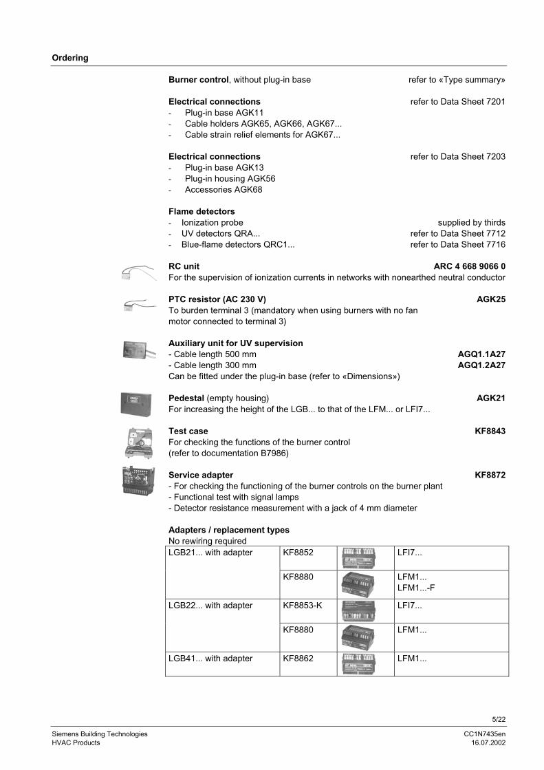
Burner control, without plug-in base refer to «Type summary»
Electrical connections refer to Data Sheet 7201- Plug-in base AGK11- Cable holders AGK65, AGK66, AGK67...- Cable strain relief elements for AGK67...
Electrical connections refer to Data Sheet 7203- Plug-in base AGK13- Plug-in housing AGK56- Accessories AGK68
Flame detectors- Ionization probe supplied by thirds- UV detectors QRA... refer to Data Sheet 7712- Blue-flame detectors QRC1... refer to Data Sheet 7716
RC unit ARC 4 668 9066 0For the supervision of ionization currents in networks with nonearthed neutral conductor
PTC resistor (AC 230 V) AGK25To burden terminal 3 (mandatory when using burners with no fanmotor connected to terminal 3)
Auxiliary unit for UV supervision- Cable length 500 mm AGQ1.1A27- Cable length 300 mm AGQ1.2A27Can be fitted under the plug-in base (refer to «Dimensions»)
Pedestal (empty housing) AGK21For increasing the height of the LGB... to that of the LFM... or LFI7...
Test case KF8843For checking the functions of the burner control(refer to documentation B7986)
Service adapter KF8872- For checking the functioning of the burner controls on the burner plant- Functional test with signal lamps- Detector resistance measurement with a jack of 4 mm diameter
Adapters / replacement typesNo rewiring required
KF8852 LFI7...LGB21... with adapter
KF8880 LFM1...LFM1...-F
KF8853-K LFI7...LGB22... with adapter
KF8880 LFM1...
LGB41... with adapter KF8862 LFM1...
6/22
Siemens Building Technologies CC1N7435enHVAC Products 16.07.2002
Technical data
Mains voltage AC 220 V –15 % ...AC 240 V +10 %(LGB2... / LGB4...)
AC 230 V –15 % / +10 % (LGB32..!)AC 100 V –15 % ...AC 110 V +10 %
Mains frequency 50...60 Hz ±6 %Input current at terminal 12 max. 5 A
within the permissible voltage rangeAC 187...264 V or AC 195...253 V
Current rating- Terminal 3
- Terminals 4, 5 and 7- Terminals 9 and 10- Terminal 12
max. 3 A(15 A for max. 0.5 s)
max. 2 Amax. 1 Amax. 5 A
(at Umax. AC 264 V or AC 253 V)Cable length terminals 8 and 10 20 m at 100 pF / mPerm. cable lengthsDetector cable laid separately
max. 3 m at 100 pF / m line capacitance20 m
Power consumption 3 VAPrimary fuse max. 10 A (slow)Degree of protection IP 40 (excluding the connection area)Mounting position optionalWeight approx. 230 g
Environmental conditionsTransport DIN EN 60 721-3-2Climatic conditions class 2K2Mechanical conditions class 2M2Temperature range -50...+60 °CHumidity < 95 % r.h.Operation DIN EN 60 721-3-3Climatic conditions class 3K5Mechanical conditions class 3M2Temperature range -20...+60 °CHumidity < 95 % r.h.
Condensation, formation of ice and ingress of water are not permitted!
General unit dataLGB...
Norms and standards
7/22
Siemens Building Technologies CC1N7435enHVAC Products 16.07.2002
Flame supervision
At mains voltage UN = AC 230 VDetector voltage across terminals 1 and2 or ground(AC voltmeter Ri � 10 M�)
� UN
Detector current required for reliable operation � 3µAPossible detector current in operation max. 100 µA
The conductivity and rectifying effect of hot flame gases are used for flame supervision.For that purpose, AC voltage is applied to the heat-resistant ionization probe whichprojects into the flame. The current that flows in the presence of a flame (ionizationcurrent) produces the flame signal which is fed to the input of the flame signal amplifier.The amplifier is designed such that it only responds to the DC current component of theflame signal, thereby ensuring that a short-circuit between ionization probe and groundcannot simulate a flame signal (since in that case AC current would flow).
Basically, the flame supervision circuit is insensitive to adverse effects of the ignitionspark.
However, should the disturbing effects of the ignition spark on the ionization currentexceed a certain level, the electrical connections on the primary side of the ignitiontransformer must be changed and / or the location of the ionization probe must bechecked.
Since the ionization current with burner controls operating on AC 110 V is only about 50% of those operating on AC 230 V, certain applications make it necessary to increasethe ionization current with a transformer.
Capacity of transformer: Min. 2 VATransforming ratio: Approx. 1.1...1.5The primary and secondary windings of the transformer must be galvanically sepa-rated.
L N
AC 110 V
LGB2...
12 2
1AC 110...240 V74
35v0
1/12
99 FE
Flame supervision withionization probe
Ionization current su-pervision with burnercontrols operating onAC 110 V
Connection oftransformer
8/22
Siemens Building Technologies CC1N7435enHVAC Products 16.07.2002
Perm. detector current during the prepurgetime (dark current)
5 µA
Min. detector current required duringoperation
50 µA
Measurement circuit with the QRC1...
M
sw- +
br
bl
1 12 2
LGB3...
7435
v02/
0601
QRC1
LegendM Microammeter Ri max. 5000 �sw Black wirebr Brown wirebl Blue wire
The QRC1... has been designed specifically for blue-burning flames. Incidence of lightis from the front and laterally. The flame detector is secured by means of a soft plasticplug. 3-core connection (preamplifier integrated in the detector casing). For the differenttypes of flame detectors, engineering notes and technical data, refer to Data Sheet7716.
Mains voltage AC 220 V –15 %...AC 240 V +10 %Mains frequency 50...60 Hz �6 %Power consumption 4.5 VADegree of protection IP 40Perm. ambient temperature- In operation- During transport and storage
-20...+60 °C-40...+70 °C
Perm. length of cable from QRA... toAGQ1...A27 (use separate cable)
max. 20 m
Mounting position optionalPerm. length of connecting cable fromAGQ1...A27 to LGB...
max. 20 m
Weight of AGQ1...A27 approx. 140 g
At mains voltage UN:AC 220 V AC 240 V
Detector voltage at QRA... (with no load)Up to the end of «t10» and after a controlled shutdown DC 400 V DC 400 VFrom the beginning of «t1» DC 300 V DC 300 VDetector voltageLoad by DC measuring instrument Ri > 10 M�
Up to the end of «t10» and after controlled shutdown DC 380 V DC 380 VFrom the beginning of «t1» DC 280 V DC 280 VDC detector signals with UV detector QRA... Min. required Max. possibleMeasurement on the QRA... 200 µA 500 µA
Siemens Building Technologies CC1N7435enHVAC Products 16.07.2002
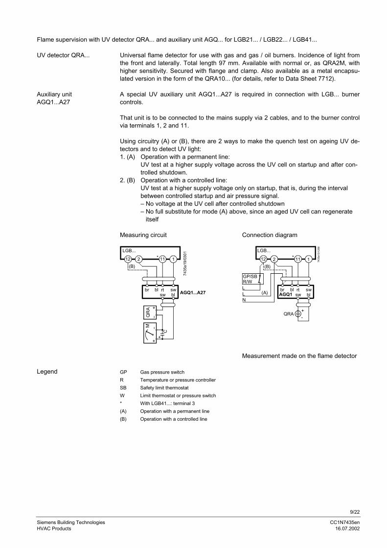
Flame supervision with UV detector QRA... and auxiliary unit AGQ... for LGB21... / LGB22... / LGB41...
Universal flame detector for use with gas and gas / oil burners. Incidence of light fromthe front and laterally. Total length 97 mm. Available with normal or, as QRA2M, withhigher sensitivity. Secured with flange and clamp. Also available as a metal encapsu-lated version in the form of the QRA10... (for details, refer to Data Sheet 7712).
A special UV auxiliary unit AGQ1...A27 is required in connection with LGB... burnercontrols.
That unit is to be connected to the mains supply via 2 cables, and to the burner controlvia terminals 1, 2 and 11.
Using circuitry (A) or (B), there are 2 ways to make the quench test on ageing UV de-tectors and to detect UV light:1. (A) Operation with a permanent line:
UV test at a higher supply voltage across the UV cell on startup and after con-trolled shutdown.
2. (B) Operation with a controlled line:UV test at a higher supply voltage only on startup, that is, during the intervalbetween controlled startup and air pressure signal.– No voltage at the UV cell after controlled shutdown– No full substitute for mode (A) above, since an aged UV cell can regenerate itself
Measuring circuit Connection diagram
12 2 11* 1
7435
a19/
0301
br bl rt sw AGQ1...A27sw bl
(B)
LGB...
QR
A
12 2 11* 1 7435
a15/
1299
GP/SBR/WLLN
QRA+-
br bl rt swAGQ1 sw bl
(B)
(A)
LGB...
Measurement made on the flame detector
GP Gas pressure switchR Temperature or pressure controllerSB Safety limit thermostatW Limit thermostat or pressure switch* With LGB41...: terminal 3(A) Operation with a permanent line(B) Operation with a controlled line
UV detector QRA...
Auxiliary unitAGQ1...A27
Legend
10/22
Siemens Building Technologies CC1N7435enHVAC Products 16.07.2002
Functions
The function diagrams show the required or permissible input signals to the controlsection and to the flame supervision circuit hatched (refer to «Connection diagrams»).If these input signals are not present, the burner control will stop the startup sequence totrigger lockout where required by safety regulations.
- Burner control must be reset- The contacts of gas pressure switch «GP», limit thermostat / pressure switch «W»,
control thermostat / pressurestat «R» and safety limit thermostat «SB» must beclosed
- Fan motor «M» or AGK25 must be connected- Air pressure switch «LP» must be in its no load position
LGB... burner controls are capable of detecting undervoltages. This means that loadrelay «AR» will be deenergized if mains voltage drops below AC 160 V (for nominal AC220...240 V) or AC 75 V (for nominal AC 100...110 V).The burner control will automatically make a restart attempt when the supply voltagereturns to a level above AC 160 V and AC 75 V respectively.
If the connections of live conductor (terminal 12) and neutral conductor (terminal 2) aremixed up, the burner control will initiate lockout at the end of «TSA».
A – C Startup sequence
A Start command (switching on)This command is triggered by control thermostat / pressurestat «R».Terminal 12 receives voltage and the programming mechanism starts running.On completion of waiting time «tw» with the LGB21..., or after air damper«SA» has reached the nominal load position (on completion of «t11») with theLGB22... / LGB32..., fan motor «M» will be started.
TSA Ignition safety timeOn completion of «TSA», a flame signal must be present at terminal 1.That flame signal must be continuously available until shutdown occurs, orelse flame relay «FR» will be deenergized, resulting in lockout.
tw Waiting timeDuring the waiting time, air pressure switch «LP» and flame relay «FR» aretested for correct contact positions.
t1 Prepurge timePurging the combustion chamber and the secondary heating surfaces:Required with low-fire air volumes when using the LGB21... and with nominalload air volumes when using the LGB22... / LGB32...«Type summary» and the «Function and sequence diagrams» show the so-called prepurge time «t1» during which air pressure switch «LP» must indi-cate that the required air pressure is available.The effective prepurge time «t1» comprises interval end «tw» through «t3».
t3 Preignition timeDuring «t3» and up to the end of «TSA», flame relay «FR» is forced to close.On completion of «t3», the release of fuel is triggered at terminal 4 or at termi-nal 11 of the LGB41...
Preconditions forburner startup
Undervoltages
Reversed polarityprotection
Startup sequence
11/22
Siemens Building Technologies CC1N7435enHVAC Products 16.07.2002
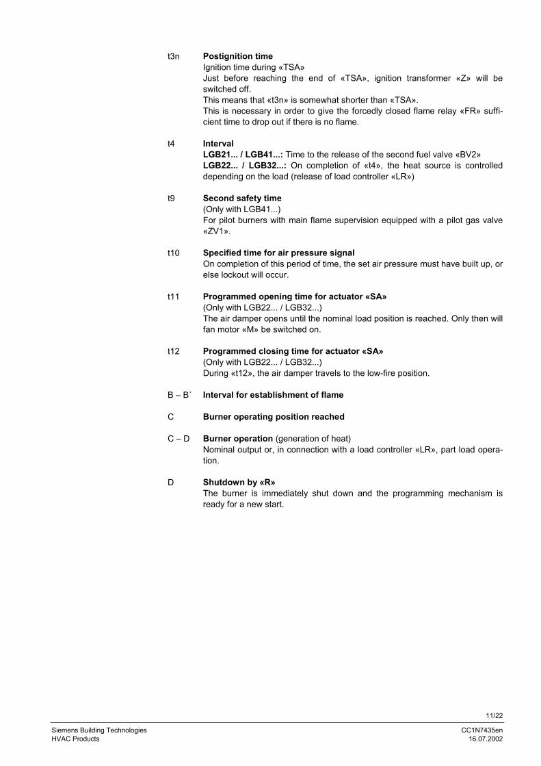
t3n Postignition timeIgnition time during «TSA»Just before reaching the end of «TSA», ignition transformer «Z» will beswitched off.This means that «t3n» is somewhat shorter than «TSA».This is necessary in order to give the forcedly closed flame relay «FR» suffi-cient time to drop out if there is no flame.
t4 IntervalLGB21... / LGB41...: Time to the release of the second fuel valve «BV2»LGB22... / LGB32...: On completion of «t4», the heat source is controlleddepending on the load (release of load controller «LR»)
t9 Second safety time(Only with LGB41...)For pilot burners with main flame supervision equipped with a pilot gas valve«ZV1».
t10 Specified time for air pressure signalOn completion of this period of time, the set air pressure must have built up, orelse lockout will occur.
t11 Programmed opening time for actuator «SA»(Only with LGB22... / LGB32...)The air damper opens until the nominal load position is reached. Only then willfan motor «M» be switched on.
t12 Programmed closing time for actuator «SA»(Only with LGB22... / LGB32...)During «t12», the air damper travels to the low-fire position.
B – B´ Interval for establishment of flame
C Burner operating position reached
C – D Burner operation (generation of heat)Nominal output or, in connection with a load controller «LR», part load opera-tion.
D Shutdown by «R»The burner is immediately shut down and the programming mechanism isready for a new start.
12/22
Siemens Building Technologies CC1N7435enHVAC Products 16.07.2002
In principle, whenever lockout occurs, the fuel supply will immediately be shut down. Ifthat takes place between startup and preignition, which is not indicated by a symbol,the usual cause is air pressure switch «LP» shutting down, or a premature, faulty flamesignal.
� After a mains failure or in the event of un-dervoltage:
New startup with full program sequenceon power restoration
� Premature flame signal from the start of «t1»: Immediate lockout� Contacts of air pressure switch «LP» have
welded during «tw»:Prevention of startup
� No air pressure signal: Lockout on completion of «t10»� Air pressure failure on completion of «t10»: Immediate lockout� Burner does not ignite: Lockout on completion of «TSA»� Flame is lost during operation: Immediate lockout
After lockout, the LGB... will remain locked (lockout cannot be changed).This state will also be maintained in the event of mains voltage failure.
Whenever lockout occurs, the burner control can immediately be reset.
Control sequence inthe event of fault
Lockout
Resetting the LGB...
13/22
Siemens Building Technologies CC1N7435enHVAC Products 16.07.2002
Lockout and control sequence indication
The position of the programming mechanism can be seen through the viewing windowon the front of the unit. In the event of fault, the programming mechanism stops andthus the lockout indicator also. The symbol in the viewing window indicates both theposition in the control sequence and the type of fault according to the following legend:
� No startup since the start control loop is open
IIII Interval «tw» or «t10» (LGB21...)Interval «tw» or «t11» (LGB22... / LGB32...)Interval «tw», «t3» or «TSA» (LGB41...)
1 Lockout since there is no flame signal on completion of the first safety time
2 Release of second fuel valve (LGB21... / LGB41...)Release of load controller (LGB22... / LGB32...)
3 Lockout since there is no flame signal on completion of the second safety time(LGB41...)
���� Part load or nominal load operation (or return to the operating position)
14/22
Siemens Building Technologies CC1N7435enHVAC Products 16.07.2002
Connection diagrams
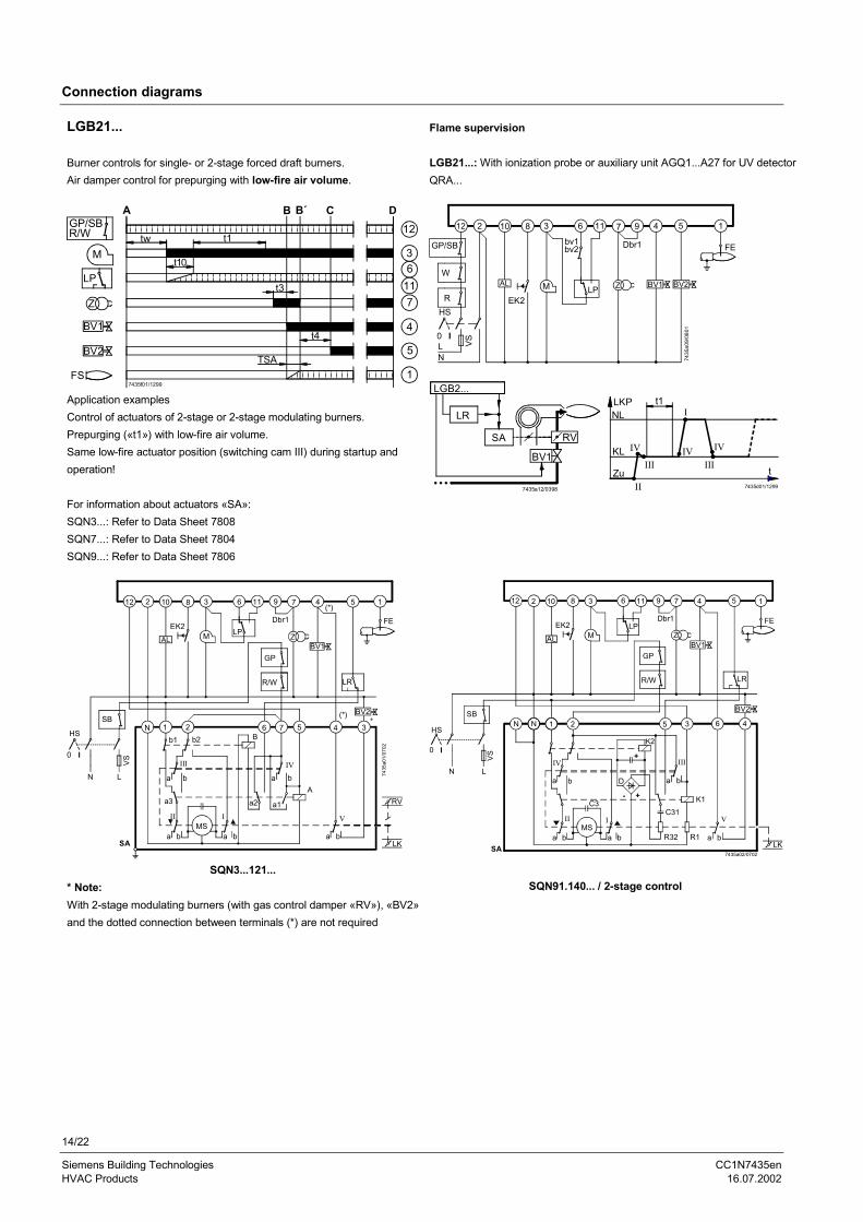
LGB21... Flame supervision
Burner controls for single- or 2-stage forced draft burners.Air damper control for prepurging with low-fire air volume.
LGB21...: With ionization probe or auxiliary unit AGQ1...A27 for UV detectorQRA...
GP/SBR/W
M
12
36
117
4
5
17435f01/1299
A B B´ C D
tw
t10
t1
TSA
t3
t4
LP
Z
BV1
FS
BV2
Application examplesControl of actuators of 2-stage or 2-stage modulating burners.Prepurging («t1») with low-fire air volume.Same low-fire actuator position (switching cam III) during startup andoperation!
For information about actuators «SA»:SQN3...: Refer to Data Sheet 7808SQN7...: Refer to Data Sheet 7804SQN9...: Refer to Data Sheet 7806
12 2 10 8 3 6 11 7 9 4 5 1
GP/SB
W
RHS
0 ILN
AL
EK2M LP
bv1bv2 Dbr1
Z BV2
FE
7435
a09/
0801
BV1
VS
LGB2...
LR
SA
BV1
RV
7435a12/0398 II
KL
ZuIII
LKPNL
t1
IV
IIIIV
I
t
IV
7435d01/1299
12 2 10 8 3 6 11 9 7 4 5 1
HS
0 I
N L
AL
EK2M LP
GP
R/W
ZBV1
(*)
LR
FE
BV2*
(*)N 1 2 6 7 5 4 3
b1 b2 B
a b
III
a3
a b
IIMS
I
a b
a2
a bIV
A
a b
V
RV
LK
7435
a01/
0702
Dbr1
a1
SA
VS
SB
SQN3...121...* Note:With 2-stage modulating burners (with gas control damper «RV»), «BV2»and the dotted connection between terminals (*) are not required
12 2 10 8 3 6 11 9 7 4 5 1
AL
EK2M
LP
GP
R/W
Dbr1
ZBV1
LR
FE
BV2
HS
N L
0 I
N N 1 2 5 3 6 4
7435a02/0702
LKSA
IV
IIMS
I
C3
D
K2
C31
III
R32 R1
V
K1
a b
a b a b ba
a b
- +
+VS
SB
SQN91.140... / 2-stage control
15/22
Siemens Building Technologies CC1N7435enHVAC Products 16.07.2002
1
b1
LP
HS8N 4
N
I
L
B
a1
A
LGB21...
12
EK2
AL
2 10 3
5 3 2 7 6
b2
a2
M
c1
C
R/W
GP
6 11 4
FE
5 1
0
7435
a03/
0702
8
IIIII IVI
Z
BV1
LR
7
BV2
M
I
KL
zu
NLLKP
t
I
III III
IV IV
IITSAt4
t1
9
VS
SB
SQN7...244 / 2-stage control
Burner without fan and without «LP»2 3 11 6
AGK25
7435a04/0398
Burner with fan control via auxiliary contactor («HS») with «LP»(does not apply to LGB41...)
12 2 3 11 6
GP/SBR/W
LN
M
HS AGK25 LP
7435a16/1299
QRC1... with LGB3... (diagram 7435a02)QRA... with auxiliary unit AGQ1... with LGB2... / LGB4... (diagram7435a06)
2 12 1bl br sw
QRC7435
a05/
1299
12 2 11* 1
7435a06/1299
GP/SBR/WLLN
QRA +-
br bl rt swAGQ1 sw bl
Legendbl Blue wirebr Brown wirert Red wiresw Black wire
* With LGB41... terminal 3
16/22
Siemens Building Technologies CC1N7435enHVAC Products 16.07.2002
Connection diagrams
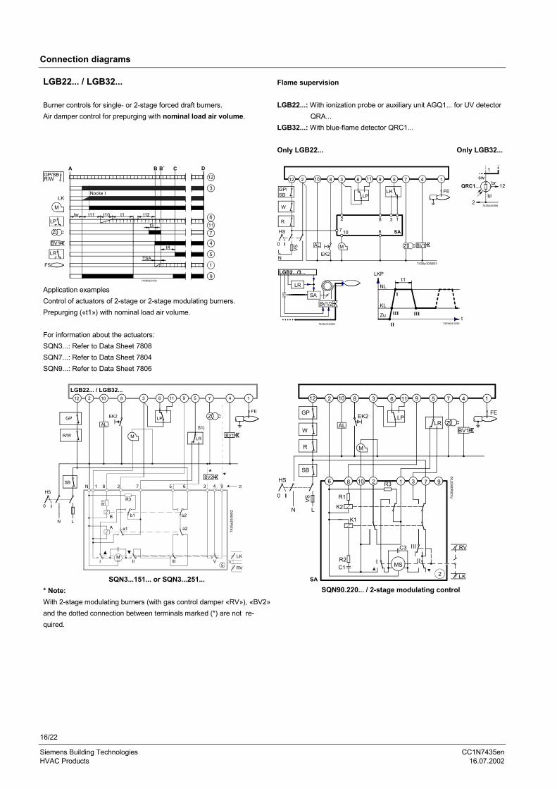
LGB22... / LGB32... Flame supervision
Burner controls for single- or 2-stage forced draft burners.Air damper control for prepurging with nominal load air volume.
LGB22...: With ionization probe or auxiliary unit AGQ1... for UV detector QRA...LGB32...: With blue-flame detector QRC1...
Only LGB22... Only LGB32...
GP/SBR/W
M
LP
Z
BV1
LR
FS
A B B´ C D12
6117
4
5
1
97435f02/0700
tw t11 t1 t12t10
TSA
t3
t4
3
LKNocke I
Application examplesControl of actuators of 2-stage or 2-stage modulating burners.Prepurging («t1») with nominal load air volume.
For information about the actuators:SQN3...: Refer to Data Sheet 7808SQN7...: Refer to Data Sheet 7804SQN9...: Refer to Data Sheet 7806
LR
SA
LGB2.../3...
BV1/2
7435a13/0398
1sw
QRC1... 12br
bl2
7435i04/0398
KL
Zu III
LKP
NLt1
IIIt
7435d02/1299
I
II
12 2 10 8 3 6 11 9 5 7 4 1
GP/SB
W
R
HS
0 ILN
AL
EK2M
LPLR
Z BV1
FE
7435a10/0801
7
2
10 6
8 3 1
SA
VS
12 2 10 8 3 6 11 9 7 45 1
HS
0 I
N L
EK2
M
LPGP
R/W
Z
BV1LR
FE
AL
LGB22... / LGB32...
N 1 8 2 7 5 6 3 4 9
B b1 b2
A a1 a2
IM
II III V5
LK
RV1)
7435
a20/
0602
S1)
BV2
2)SB
* *
R3
R1
SQN3...151... or SQN3...251...* Note:With 2-stage modulating burners (with gas control damper «RV»), «BV2»and the dotted connection between terminals marked (*) are not re-quired.
12 2 10 8 3 6 11 9 5 7 4 1
GP
W
R
ALEK2
M
LPLR Z
BV1
FE
HS
0 I
N L
6 8 10 2 1 3 7 9
7435
a08/
0702
RV
LKSA
R1
K2
R3
K1
R2C1
I MS
C3 III
II
VS
SB
2
SQN90.220... / 2-stage modulating control
17/22
Siemens Building Technologies CC1N7435enHVAC Products 16.07.2002
HS
0
4N 15
N
I
L
A
b1
a1
LGB22... / LGB32...
R/W
GP
12
AL
EK2
38
3 2 68 7
b2
a2
M
B
Z
LR
FE
BV1
4 1
1 2
7435
a18/
0702
10 9 5 7
BV2
IIIIII IV
2 6 11
LP
M
VS
SB
N
I
HS
L
LGB22... / LGB32...
R/W
GP
12
EK2
38
Z
LR
5
FE
BV1
BV2
0
7435
a17/
0702BC A
a1
b1
c1
b2
a2
M
79102
N 5 4 1 3 2 8 6 7
IIIII IVI
6 11
AL
4 1
M
LKP
zu
KL
NL
t
IIIIII
IVIV
II
IIt1 TSA
t4
LPVS
SB
52
SQN7...454 / 2-stage controlSingle-wire control
SQN7...424 / 2-stage control2-wire control
TSA Ignition safety time
t1 Prepurge time
t4 Interval «BV1 – BV2»
LGB22... / LGB32...: interval «BV1 - LR»
AL Alarm LR Load controller
BV... Fuel valve M Fan motor
EK2 Remote reset button NL Nominal load
FE Ionization probe R Control thermostat or pressurestat
GP Gas pressure switch SB Safety limit thermostat
HS Mains isolator VS Primary fuse
KL Low-fire W Limit thermostat
LKP Air damper position Z Ignition transformer
LP Air pressure switch
Legend
18/22
Siemens Building Technologies CC1N7435enHVAC Products 16.07.2002
Connection diagrams
LGB41...
Burner controls for atmospheric gas burners with or without fan. No actuator control. Flame supervision with ionization probe
GP/SBR/W
Z
BV1
ZV1
BV2
FS
A B B´ C D12
7
4
11
5
17435f03/0301
tw
t3
TSA
t4
t9
12 2 10 8 3 6 11 7 9 4 5 1
GP/SB
W
R
HS
0LN
AL
EK2M
Dbr2bv1zv1
ZV1
Z
Dbr1
BV1
BV2
FE
7435a11/0801
bv2
VS
FE
HR
BV1 BV2
7435
s01/
0398
FE2 FE1
ZR
HRBV2 ZV1
7435
s02/
0398
A Startup (switching on by «R») AL AlarmB – B´ Interval for establishment of flame BV... Fuel valveC Operating position of burner or release of the second stage bv... Auxiliary switch in the fuel valves (for checking the fully
by load controller«LR» closed position)D Shutdown by «R» Dbr1 Wire link
Dbr2 Wire link, required when contact «bv» or «zv1» is missingtw Waiting time EK2 Remote reset buttonTSA Ignition safety time FE... Ionization probet3 Prepurge time FS Flame signalt4 Interval «BV1 – BV2» GP Gas pressure switcht9 Second safety time HR Main burner
HS Mains isolatorM (Auxiliary) fan motor
Required input signals R Control thermostat or pressurestatBurner control’s output signals SB Safety limit thermostat
VS Primary fuseW Limit thermostat
� Connection of valves with pilot burners with main flame Z Ignition transformersupervision ZR Pilot burner
�� Connection of valves with 2-stage atmospheric burners ZV1 Pilot gas valvewith supervision of the first stage («BV1») zv1 Auxiliary switch in the pilot gas valve
Legend
19/22
Siemens Building Technologies CC1N7435enHVAC Products 16.07.2002
Internal diagram and time diagram of the programming mechanisms
Legend
AL AlarmAR Load relay with contact «ar»AS Unit fuseBR Locking relay with contact «br»BV... Fuel valveDbr1 Wire linkEK... Lockout reset buttonFE Ionization probeFR Flame relayGP Gas pressure switchHS Mains isolatorL1 Lockout warning lampLP Air pressure switchM Fan motorMS Synchronous motorR Control thermostat or pressurestatSB Safety limit thermostatW Limit thermostat or pressure switchZ Ignition transformer
GP/SB
W R
HSL N
0 I
M
LP
7435
i01/
1299
FEDbr1Z
BV2BV1EK2AL
EK1
2 10 8 4 5 7 9 1
116
31)
12bra
bAS
Ia b
ara b
a bIV
FR
AR
fra b
IIa b a b
VIII
V VI IX VII
BR
a b abb a
MS
L1
a
A Start position (switching on)B Operating position of burnerC Operating position of programming mechanism or start
position
I...IX Cam switches
tw Waiting timeTSA Ignition safety timeT Total running time of programming mechanismt1 Prepurge timet3 Preignition timet4 Interval «BV1 – BV2»t10 Specified time for air pressure signalt20 Interval up to self-shutdown of the programming
mechanism
1) Resistance between terminal 3 and «N» may notexceed 1.6 k�
A B C
7435
f04/
0801
4
7
5
3
T = 81 s (40,5 s )FR
AR
IX
VIII
VII
V
IV
II
I ba
tw t10 t1
t3 TSA t4 t20
VI
ba
ba
ba
ba
ba
ba
ba
ba
ba
2)
2) Only with LGB21.130A27
LGB21...
20/22
Siemens Building Technologies CC1N7435enHVAC Products 16.07.2002
LGB22... / LGB32...
Legend
AL AlarmAR Load relay with contact «ar»AS Unit fuseBR Locking relay with contact «br»BV... Fuel valveEK... Lockout reset buttonFE Ionization probeFR Flame relayGP Gas pressure switchHS Mains isolatorL1 Lockout warning lampLP Air pressure switchM Fan motorMS Synchronous motorR Control thermostat or pressurestatSB Safety limit thermostatW Limit thermostat or pressure switch
GP/SB
W R
HS
0 I
L N
M
LP
7435
i02/
1299
FEZBV2
BV1EK2AL
EK1
12
31)
6 11
175498102
a
b
br
AS
I ara b a b
FR
AR
IIIab IV
a b
fra b
IIa b
VIIIa b
Vab VI
abIXa b
VII
ab
L1
BR
MS
Z Ignition transformer
Only LGB32...
1sw
QRC1... 12br
bl2
7435i04/0398
A Start position (switching on)B Operating position of burnerC Operating position of programming mechanism or start
position
I...IX Cam switches
tw Waiting timeTSA Ignition safety timeT Total running time of programming mechanismt1 Prepurge timet3 Preignition timet4 Interval «BV1 – BV2» or «BV1 – LR»t10 Specified time for air pressure signalt11 Programmed opening time for actuator «SA»t12 Programmed closing time for actuator «SA»t20 Interval up to self-shutdown of the programming
mechanism
A B C
7435
f05/
1299
9
4
7
5
3
T = 81 sFR
ab
AR
IX
VIII
VII
VI
V
IV
III
II
I
tw t11 + t10 t1 t12
t3 TSA t4 t20
ab
ab
ab
ab
ab
ab
ab
ab
ab
ab
1) Resistance between terminal 3 and «N» may not ex-ceed 1.6 k�
21/22
Siemens Building Technologies CC1N7435enHVAC Products 16.07.2002
Only LGB41...
Legend
AL Alarm
AR Load relay with contact «ar»
AS Unit fuse
BR Locking relay with contact «br»
BV... Fuel valve
Dbr1 Wire link
Dbr2 Wire link terminal 6-2 required when contact «bv» or «zv1»
is missing
EK... Lockout reset button
FE Ionization probe
FR Flame relay
GP Gas pressure switch
HR Main burner
HS Mains isolator
L1 Lockout warning lamp
M Fan motor
MS Synchronous motor
R Control thermostat or pressurestat
SB Safety limit thermostat
W Limit thermostat or pressure switch
Z Ignition transformer
ZR Pilot burner
ZV1 Pilot gas valve in place of «BV1» in the case of pilot
burners with main flame supervision
tw Waiting time
TSA Ignition safety time
T Total running time of programming mechanism
t3 Preignition time
t4 Interval «BV1 – BV2»
t9 Second safety time
t20 Interval up to self-shutdown of the programming
mechanism
A Start position ( switching on)
B Operating position of burner
C Operating position of programming mechanism or start
position
I...IX Cam switches
1) Resistance between terminal 3 and «N» may not exceed
GP/SB
W R
M
HSL N
7435
i03/
1299
FEDbr1ZBV1D
br2
EK2AL
EK1
a
bAS
br 12
Ia b a b
ar
1)3
IIIb a
FR
AR
MS
8
VIIIa
bIIa b
BR
L1
2 10 11 46 5 7 9 1
VIIbba
IXVIb a
IVa
Va
fra b
BV2ZV1
0 I
A B C
6
11
4
7
5
tw t3 TSA t4 t20
t9
ab
AR
FRT = 40,5 s
ab
ab
ab
ab
ab
ab
ab
ab
ab
ab
I
II
III
IV
V
VI
VII
VIII
IX
7435
f06/
0301
FE
HR
BV1 BV2
7435
s01/
0398
FE2 FE1
ZR
HRBV2 ZV1
7435
s02/
0398
1.6 k�
22/22
Siemens Building Technologies CC1N7435enHVAC Products 16.07.2002
DimensionsDimensions in mm
50-60 Hz
ÖVGW - G 1.896
CE-0085AO0087ts max. 3sec.
3 VA
FI
Rg. 5 F015/98
NLANDIS & GYR
LGB22.330A27220-240 V~
DIN
5,5
62,5
9
2525
88
91
1
41,5
23,8
10
37,8 5
2247
62,5Made in Germany
7435
m03
/129
9
ÖVES
9911290057
90,560
220 69 6
AB 6
5,4 5,4
13
18
465
,627
,5
7435m01/0301
Burner control withplug-in base AGK11...and cable gland holderAGK65...
Auxiliary unitAGQ1...A27 Type Dimension
reference A B
AGQ1.1A27 500 19
AGQ1.2A27 300 34
�2002 Siemens Building Technologies AGSubject to change!


![hf]lvd Joj:yfkg of]hgf th'{df lgb]{lzsf, @)^*...:yfgLo -;fd'bflos tyf uflj;_ ljkb\hf]lvd Joj:yfkg of]hgf th'{df lgb]{lzsf, @)^*÷3:yfgLo ljkb\hf]lvd Joj:yfkg of]hgf th'{df lgb]{lzsf,](https://static.documents.pub/doc/80x56/5e663607b7760263f10c10ab/hflvd-jojyfkg-ofhgf-thdf-lgblzsf-yfglo-fdbflos-tyf-uflj-ljkbhflvd.jpg)


![h}t'g v]tL MANU… · h}t'g v]tL-k|fljlws lgb]{lzsf_ Olive Manual kmnk"mn ljsf; lgb]{zgfno sLlt{k'/, sf7df8f}+ @)&#](https://static.documents.pub/doc/80x56/60da53386dbd830d4328d692/htg-vtl-manu-htg-vtl-kfljlws-lgblzsf-olive-manual-kmnkmn-ljsf.jpg)


